

Page 1

INSTALLATION MANUAL
1010-0093, REV 03
Fax: 425/745-3429 • E-mail: maple@maple-systems.com • URL: www.maple-systems.com
808 134th Street SW, Suite 120 • Everett, WA 98204 • USA • 425/745-3229
Page 2

2 MAP460D
COPYRIGHT NOTICE
This manual is a publication of Maple Systems, Inc., and is provided for use by its customers only. The
contents ofthe manual arecopyrighted by MapleSystems, Inc.; reproductionin whole orin part, for use
other thanin support of MapleSystems equipment, isprohibited without the specificwritten permission
of Maple Systems.
WARRANTY
Maple Systemswarrants each product to be free from electricaland mechanical defects in materials and
workmanship for aperiod of one year fromthe date of shipment. This warranty doesnot apply to defects
in theProducts caused by abuse,misuse, accident, casualty, alteration,negligence, repair notauthorized
by Maple Systems, use on current or voltages other than specified by Maple Systems, or application or
installation not in accordance with published instruction manuals. This warranty is in lieu of any other
warranty either expressed or implied.
Maple Systems’ liability is limited to the repair or replacement of the Product only, and not costs of
installation, removal, or damage to user’s property or other liabilities. If Maple Systems is unable to
repair or replace a nonconforming Product, it may offer a refund of the amount paid to Maple Systems
for such Product in full satisfaction of its warranty obligation. Maximum liability of Maple Systems is
the cost of the Product.
Information furnished by Maple Systems, Inc., is believed to be accurate and reliable. However, no
responsibility is assumed by Maple Systems for the use of this information nor for anyinfringements of
patents or other rights of third parties which may result from its use. No license is granted by
implication, or otherwise, under any patent or patent rights of Maple Systems, Inc. Maple Systems
retains the right to revise or change its products and documentation at any time without notice.
IF SERVICE IS REQUIRED
Package the unit in its original packaging container or, if unavailable, any suitable rigid container. If a
substitute container is used, surround the unit with shockabsorbing material; damage in shipment is not
covered by thewarranty. Include aletter with the unitdescribing the difficulty anddesignating a contact
person. Send to the following address: Maple Systems, Inc., 808 134th Street SW, Suite 120, Everett,
WA 98204.
Only Products that have been issued a Return Material Authorization (RMA) number from Maple
Systems may be returned. All RMAs must be accompanied with a written purchase order for tracking
purposes or, in the case of out-of-warranty repairs, for repair charges on a time and material basis.
All returns will be tested to verify customer claims of noncompliance with the product warranty.
Improper return packaging which makes verification impossible will void the warranty. Products
passing the tests will be returned “AS IS” to the customer.
If noncompliance is verified and is not due to customer abuse or the other exceptions described with
product warranty, Maple Systems will, at its option, repair or replace the Product returned to it, freight
prepaid, which fail to comply with the foregoing warranty, provided Maple Systems is notified of such
noncompliance within the one-year warranty period.
1010-0093, REV 03
APPLICATIONS ASSISTANCE
This manualis designed to provide thenecessary information for trouble-free installation and operation
of your new Operator Interface Terminal (OIT). However, if you need assistance, please call Maple
Systems at 425-745-3229 or visit our web site at www.maple-systems.com.
Page 3

INSTALLATION MANUAL 3
Read Me First!
Your new Maple Systems OIT comes from the factory without any
communications protocol or operational software installed; therefore
The OIT will NOT operate until it has been configured using
•
MAPware-100 or STEPware-100.
When power is first applied, the OIT’s display will indicate that it
•
needs to be configured.
•
Use the MAPware-100 or STEPware-100 software to create a file
(or “project”) that can be downloaded to the OIT.
•
When the project is transferred, both communications protocol
and operational software are automatically loaded and the unit is
ready for operation.
To ensure that the OIT meets CE compliance, it is necessary to
follow all installation procedures described in this manual.
1010-0093, REV 03
Page 4

4 MAP460D
Introduction
Thank you for purchasing a Maple Systems MAP460D. You have selected a
rugged, reliable, and powerful operator interface for yourapplication. This booklet
describes the steps necessary to ensure trouble-free OIT system operation. Please
read this booklet carefully!!
Static Awareness
It is best NOT to remove the rear cover on the OIT except when accessing the
terminal block pins, panel mounting the OIT or replacing the real-time clock
battery. When the rear cover is removed, the circuitry inside is exposed to possible
damage by electrostatic discharge during handling. Minimize the possibility of
CAUTION
electrostatic discharge by:
Discharging personal static by grounding yourself prior to handling the OIT.
•
Handling the OIT at static-free, grounded work stations.
•
Connecting the chassis of the OIT to a clean ground.
•
• Placing the OIT into an anti-static bag during transport.
Unpacking the Unit
Carefully unpack the OIT. Please read any instructions or cautions that appear on
the shipping container. Check all material in the container against the enclosed
packing list. Maple Systems, Inc., will not accept responsibility for shortages
against the packing list unless notified within 30 days. The equipment and its
accessories were inspected and testedby Maple Systems before shipment; all of the
equipment should be in good working order. Examine the equipment carefully; if
any shipping damage is evident, notify the carrier immediately. You are
responsible for claim negotiations with the carrier. Save the shipping container and
packing material in case the equipment needs to be stored, returned to Maple
Systems, or transported for any reason.
1010-0093, REV 03
Page 5

INSTALLATION MANUAL 5
TABLE OF CONTENTS
1. Control Panel Design Guidelines ...................................6
1.1. Control Panel Grounding ....................................6
1.2. Power Supply Selection .....................................6
1.3. OIT Cable Routing .........................................7
1.4. Other Steps to Improve Noise Immunity ........................7
2. OIT Installation.................................................8
2.1. Set Jumper for Specific Protocol...............................8
2.2. Connect OIT to PLC/Host and Power...........................9
2.3. Mounting the Operator Interface Terminal ......................11
3. OIT Configuration Wiring .......................................14
3.1. Connect MAP460D to PC for Configuration ....................14
4. Battery Replacement............................................15
Appendix A: OIT Hardware Specifications.............................16
Appendix B: Differences Between MAP460D and MAP460C..............18
1010-0093, REV 03
Page 6
6 MAP460D
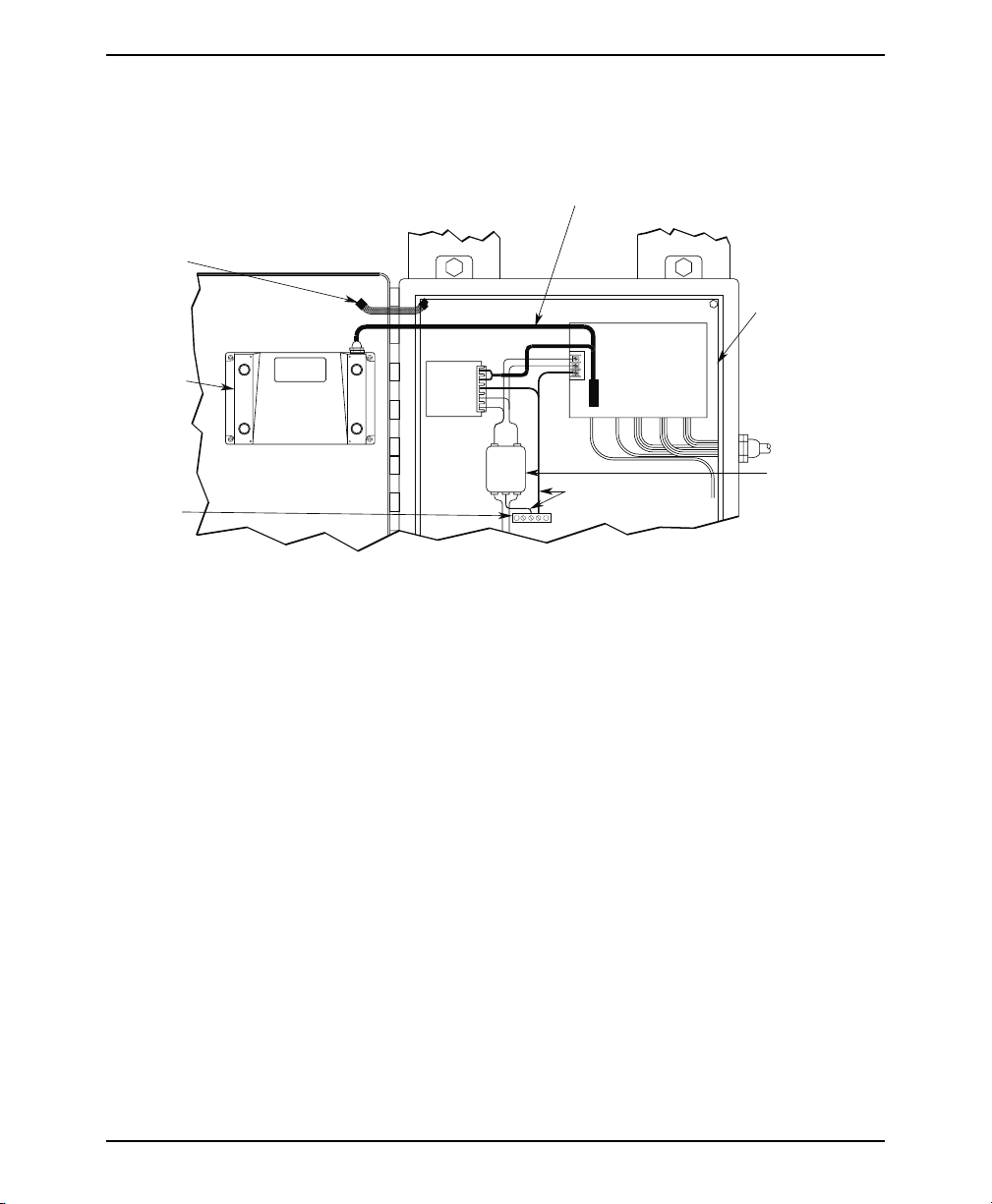
1. Control Panel Design Guidelines
Pay careful attention to the placement of system components and associated cable
routing. These items can significantly enhance the performance and integrity of
your control application.
SHIELDED
COMMUNICATION
CABLE
GROUND
STRAP
OIT OPERATING
CABLE
OIT REAR
COVER
QUIET
GROUND
OIT
Figure 1 Control Panel Example
OIT
POWER
SUPPLY
1.1. Control Panel Grounding
• The control panel should be connected to a good, high-integrity earth ground
both for safety considerations and shielding purposes. This must be a reliable
earth ground with a low-resistance path. The ideal earth ground would be a
copper grounding rod located close to the OIT and the control panel.
•
Hinged doors on control panels do not provide a long term electrical connection
to the rest of the enclosure. Corrosion develops over time and prevents good
electrical contact. For this reason, a separate wire braid should be installedfrom
the hinged control panel to the rest of the enclosure.
1.2. Power Supply Selection
•
The power supply used to power the OIT should have an output between +12
and +30 VDC. The voltage should measure between +12 and +30V at the OIT
between Pins 2 and 3 of the OIT terminal block. A 24 VDC, 0.5 amp linear
power supply dedicated to the OIT is recommended.
•
The power leads on the operating cable for the OIT should be 18AWG
2-conductor wire with a shield wire and protective shield foil. The shield of the
OIT operating cable must be connected to earth ground at both ends of the cable.
Please refer to Section 2.2.
LINE
FILTER
CONTROLLER
I / O CONTROL LINES
GROUND WIRES
QUIET GROUND(ISOLATED)
CONTROL PANEL
TIED TO RELIABLE
EARTH GROUND
POWER LINE
FILTER
1010-0093, REV 03
Page 7

INSTALLATION MANUAL 7
A power line filter installed at the AC input to the OIT power supply is highly
•
recommended as a safeguard against conducted RF noise, which is often present
on factory power lines. The wires connecting the output of the power line filter
to the power supply should be kept as short as possible to minimize any
additional noise pickup. The case of thepower line filter should be connected to
a quiet earth ground. The power line filtershould have a current rating of at least
three amps with common mode and differential mode attenuation.
POWER SUPPLY
GND
AC
AC
TO EARTH
GROUND
"QUIET" GROUND
WHITE TO
110VAC NEUTRAL
BLACK TO
110VAC LOAD(HOT)
Figure 2 Power Line Filter Connection
N
G
LINE FILTER
L
N
AC
L
KEEP SHORT
GREEN
WHITE
BLACK
• The power supply that provides power to the OIT should not be used to power
switching relays orsolenoids unless noise filter caps are connectedto each relay.
1.3. OIT Cable Routing
• Always route the OIT operating cable away from any AC voltage or PLC/host
control wires.
• Never bundle the OIT cables together with 120 VAC power wires or with relay
wiring.
• Try to keep at least 8 inches (20 cm) of separation between the OIT cables and
other power wiring. If voltages greater than 120 VAC are used in the system,
greater separation is required.
•
If the OITcables must come near AC wiring, makesure they cross at 90degrees.
•
Running AC powerwires in aseparate grounded conduitis the preferredmethod
for electrical noise reduction.
•
Keep the lengths of the OIT cables as short as possible. Do not coil excess cable
and place it next to AC powered equipment.
1.4. Other Steps to Improve Noise Immunity
•
Always install the OIT’s rear cover. This provides a shield against electrical
noise which can be generatedin the control panel by relays, motors, powerlines,
and/or high frequency equipment. Ensure that all rear cover mounting screws
are properly secured.
•
Any equipment used in the enclosure that operates at high frequency or high
current levels can be covered with a grounded metal shield.
1010-0093, REV 03
Page 8

8 MAP460D
2. OIT Installation
It is necessary to follow all installation procedures described in this chapter for
electrical noise immunity and CE compliance.
2.1. Set Jumper for Specific Protocol
This step is required for a few protocols only. Consult the Protocol Guides in your
documentaion. If the protocol requires RS-485 half-duplex 3-wire
communication, proceed as follows.
JP4
(Display)
A
B
A
JP4
(CPU Board)
JP4
A
B
Position "A",
Normal
Half-Duplex 3-Wire
B
Position "B",
RS485
Figure 3 MAP460D Jumper Installation
STEPS
1. Remove the protective cover from the rear of the unit.
CAUTION: When the rear cover is removed, the circuitry inside is exposed to
possible damage byelectrostatic discharge. Refer to Static Awarenesson page 4.
2. Locate jumper “JP4” using Figure 3 as a guide. The jumper is installed on
the upper two pins of a 3-pin header. This is called Position “A”.
3. Move the jumper to the lower two pins of the 3-pin header (Position “B”).
Ensure that the jumper is pressed fully into place.
4. Replace the rear cover and the four retaining screws.
1010-0093, REV 03
Page 9
INSTALLATION MANUAL 9
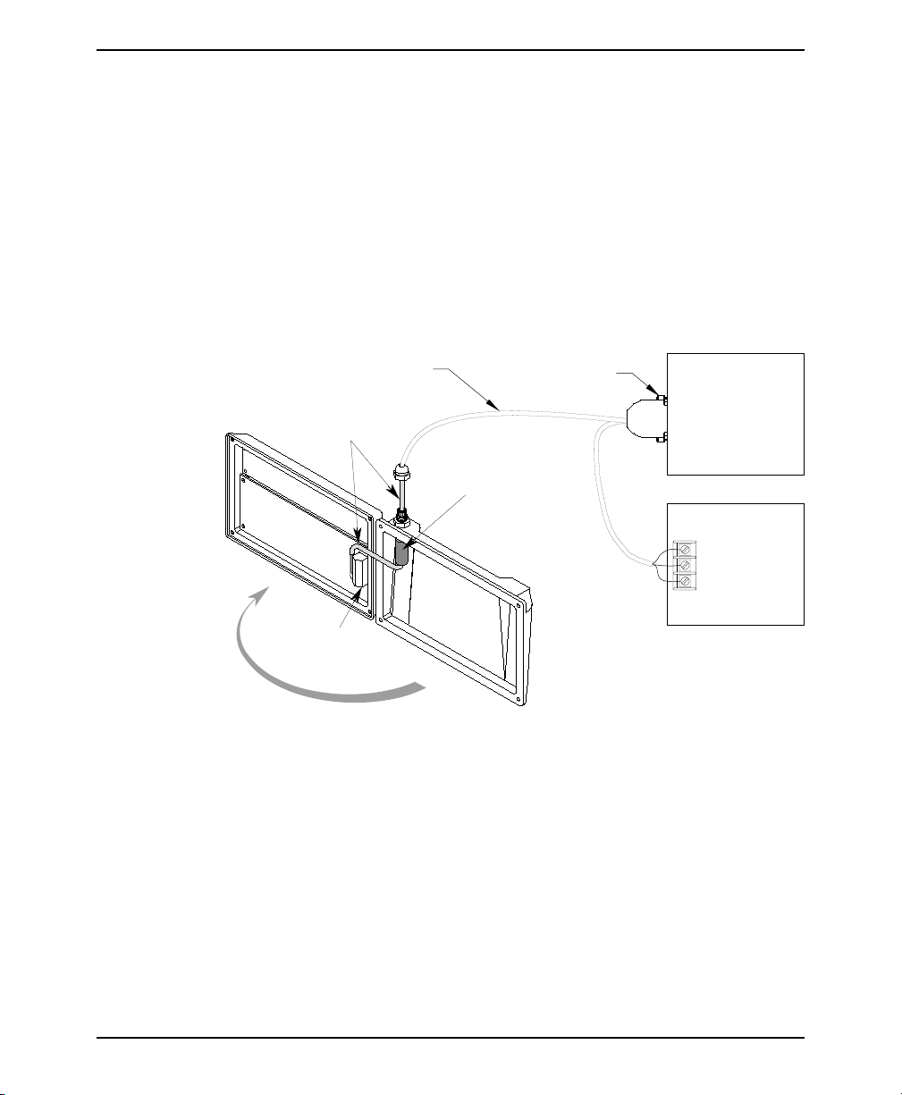
2.2. Connect OIT to PLC/Host and Power
Each PLC/host supported by Maple Systems has its own wiring requirements.
Maple Systems offers pre-constructed OIT-to-PLC operating cables for most
PLCs. Most cables are available for same day shipment from Maple Systems.
They are built and tested for high reliability and are strongly recommended.
Maple Systems also builds custom cables—contact the factory for information.
Components and instructions necessary to construct your own OIT-to-PLC
operating cables are also available. Refer toMaple Systems’ Price List orweb site
(www.maple-systems.com).
NOTE: Refer to the STEP1 Protocol Operation Manual for information on
constructing OIT-to-ASCII host operating cables.
Operating Cable
Specific for the PLC/host
OIT Operating
Cable
Tighten
Install the
Ferrite Coil here
PLC/HOST
OIT POWER SUPPLY
Output
+
-
Case GND
Terminal
Block
Figure 4 MAP460D Cable Connections
STEPS
1. Remove the four screws from the back of the OIT enclosure and open the two
halves.
2. A strain relief is provided for wiring access and sealing. The cable must be
inserted through the strain relief and into the cover.
3. Remove the black heatshrink tubing from the end of the OIT operating cable.
4. Slide the ferrite coil over the OIT operating cable. This usually requires
rotating the ferrite coil back and forth while simultaneously pulling on the
OIT operating cable.
5. Slide the ferrite coil up against the inside wall of the OIT enclosure and pull
through enough additional cable to reconnect the OIT operating cable wires.
1010-0093, REV 03
Page 10

10 MAP460D
6. Connect the OIT operating cable wires to the terminal block. Refer to the
Assembly Instruction sheets included with the Maple Systems operating
cable or connector kit. Refer to Figure 5 for the MAP460D terminal block
pinout.
7. Pull out any slack from the OIT operating cable.
8. Rotate the rear of the OIT enclosure back into position while gently pulling
out the new slack generated in the cable as you proceed.
CAUTION: Due to the large size of the ferrite coil, it must be positioned very
carefully. Make sure that when the OIT enclosure halves are brought together, the
ferrite coil is positioned so there is no internal interference. The ferritecoil must be
positioned up against the inside wall of the OIT enclosure with the protruding OIT
operating cable kept short.
9. Tighten the cable strain relief nut.
10. Re-install the four screws into the back of the OIT enclosure
11. Route the operating cable to the PLC/host and connect.
12. Route the power pigtail to the OIT power supply.
13. Install the wires into the power supply as follows:
RED +output
BLACK -output
SHIELD case ground.
1010-0093, REV 03
Function
Pin #
1
+24V
COM
RXD+
RXDTXD+
TXDRTN
RXD
TXD
CTS
RTS
2
3
4
5
6
7
8
9
10
11
12
Connection to
communication
wires of PLC/host
Figure 5 Terminal Block Pinout Connection
POWER
RS485
RS232
24V
COM
RXD
RXD
TXD
TXD
RTN
RXD
TXD
CTS
RTS
Ferrite coil
Heatshrink tubing
1
2
3
4
5
6
7
8
9
10
11
12
Chassis shield wire
Page 11

INSTALLATION MANUAL 11
2.3. Mounting the Operator Interface Terminal
Panel Mount
The OIT is installed in a panel by separating the front and rear covers of the OIT,
and then sandwichingthe panel between the two. The gasketedsurface of theOIT’s
front cover provides the environmental seal to NEMA 4 and NEMA 12 standards.
The rear cover helps shield the OIT from dust, dirt, induced electrical noise, and
physical damage.
The OIT is mounted using four
#6-32UNC screws sandwiching
the OIT halves to panel. Screw
length is equal to panel thickness
plus 1/2 inch.
NOTE: The mounting screws
must not be torqued to
more than 18 pound-inches.
Over-torquing can strip the
threads in the front half.
F3
F2
F1
F4
F7
F10
F6
F5
F9
F8
F12
F11
CLEAR
3
2
DELETE
1
6
5
E
4
N
9
T
8
E
7
R
0
-
Figure 6 MAP460D Panel Mounting
Figure 7 shows the dimensions of the panel cutout required for proper panel
installation. The panel cutout should be cleaned and deburred before the OIT is
installed.
7.580 +/-0.010
0.156 dia., 4 holes
0.180 +/-0.015
0.060 +/-0.015
7.460 +/-0.015
C
L
4.100
+/-0.015
R 0.03 max.,
4 places
4.460
+/-0.010
C
L
FRONT VIEW
Figure 7 MAP460D Panel Cutout Dimensions
1010-0093, REV 03
Page 12

12 MAP460D
IMPORTANT: When panel mounting the MAP460D, do not catch the display
connector on the panel cutout. The display is exposed while panel mounting and
extra care should be taken. The display can be damaged if the display cable
connector, which protrudes from the panel cutout, is touching the panel when
tightened. To avoid damage, place the MAP460D gently onto the panel while
monitoring for this condition.
Pedestal/Pendent Mount
The OIT is installed onto a pedestal/pendent by removing the four rubber feet from
the rear cover of the OIT, then attaching the OIT to a mounting plate using the four
pre-tapped holes inthe rear cover.The OIT enclosure and cablestrain relief provide
the environmental seal to NEMA 4 and NEMA 12 standards.
Four #6 external tooth
star lockwashers provide
chassis ground
1010-0093, REV 03
Four #6-32UNC mounting
screws secure OIT to pedestal
Figure 8 MAP460D Pedestal Mounting
Figure 9 shows the minimum dimensions of the pedestal/pendant mounting plate.
The area onthe pedestal/pendant mounting plate around the mounting holes (where
the heads of the screws make contact) should have any existing paint or plating
removed to allow for a good chassis ground connection. The mounting screws are
installed using externaltooth star washers to ensure a positiveground connection.
Page 13

INSTALLATION MANUAL 13
5.400 +/-0.015
2 places
0.156 dia. nominal,
4 holes(clearance
for #6 screws)
PEDESTAL
4.600 +/-0.015
2 places
Figure 9 Pedestal/Pendant Mounting Plate Dimensions
MOUNTING
PLATE
(1/8" thick min. recommended)
6.00 nominal
5.00 nominal
The OIT is connected to the mounting plate with four #6-32UNC screws. The
length of the mounting screws is equal to the plate thickness plus 1/4 inch.
NOTE: The mounting screws must not be torqued to more than 18 pound-inches.
Over-torquing can strip the threads in the enclosure.
Benchtop Mount
The MAP460D’s rear cover has two legs set at a five degree angle to give the display
and keypad a sloped front while sitting on a bench. Four rubber feet are attached to
the legs to prevent slippage as well as damage to the surface of the bench.
Figure 10 MAP460D Benchtop Mounting
1010-0093, REV 03
Page 14

14 MAP460D
3. OIT Configuration Wiring
The MAP460D must be configured for a particular protocol before use. The
MAPware-100 or STEPware-100 software (used on a computer with Windows 3.1
or later) is used for OIT configuration. For detailed instructions on installing and
using the software, please consult your software documentation.
3.1. Connect MAP460D to PC for Configuration
To configure theMAP460D using MapleSystems’ configuration software, remove
the operating cable from the terminal block pins and connect the OIT to the
computer using an RS-232 serial communications cable (P/N 7431-0048,
purchased separately from Maple Systems). The configuration cable should be
connected to the proper COM port on your computer, then attached to the terminal
block pins on the MAP460D. See Figure 11 below for pin assignments.
Power
Supply
GND
TXD
RXD
DCD
DTR
DSR
RTS
CTS
Red
Black
9S
5
3
2
1
4
6
7
8
Black
Shield
Red
Blk
Green
White
TB1
1
2
3
9
10
OIT
+24V
COM
RXD
TXD
+24V
GND
PC
1010-0093, REV 03
PC
Printer
Com2
OIT Power Supply
-+
GND
Figure 11 MAP460D to PC RS-232 Communication
Com1
Maple Systems
OIT to PC cable
(If mouse is using
Com 1, use Com2)
OIT
Back
of
OIT
7431-0048
Page 15

INSTALLATION MANUAL 15
4. Battery Replacement
The MAP460D is shipped with a 3V lithium coin cell battery installed for backing
up the real-time clock. During periods of power loss, the coin cell will allow the
internal clock to continue to run and keep accurate time. As long as power is
applied to the OIT, the battery will not be drained. The battery will experience no
loss of power until the OIT has been configured. Following OIT configuration, the
battery will lastfor approximately 4-6 months ifthe OIT is in acontinually powered
down state. Replacement batteries can be Ray-O-Vac or Panasonic BR1225 or
equivalent 3V coin cell batteries.
Terminal of
attery holder
Lift
Battery
+ SIDE
Battery Installation
Battery
Figure 12 Location and Installation/Removal of Battery
STEPS
1. Remove the protective cover from the rear of the unit.
CAUTION: When the rear cover is removed, the circuitry inside is exposed to
possible damage byelectrostatic discharge. Refer to Static Awarenesson page 4.
2. Find the coin cell on the PCB. It looks like a 1/2-inch (12.7 mm) silver disk.
3. Insert a small screwdriver into the top of the socket near the positive
terminal and carefully twist the screwdriver to pop the cell loose.
4. Remove the cell from the socket and discard it.
5. Place the new coin cell into the socket at an angle, noting the polarity. The
positive side is indicated by a “+” on the cell (the widest side of the
battery).
6. Press the coin cell into the socket from the rounded side of the socket. This
will allow the cell to slide into the socket. The coin cell will pop into the
socket when it has been pressed far enough in.
7. Replace the rear cover and the four retaining screws.
1010-0093, REV 03
Page 16

16 MAP460D
Appendix A
OIT Hardware Specifications
Mechanical
Material: Cast aluminum enclosure sealed to NEMA 4/12
Mounting: Panel, pedestal, pendant, or benchtop
Wiring: Unit is field-wired by user to internal terminal block pins
Weight: 2 pounds (0.90 kg)
Environmental
Operating Temp: +32 to +122°F (0 to +50°C)
Storage Temp: -4 to +158°F (-20 to +70°C)
Electric Noise Immunity
Emissions: EN55011 (Group 1, Class B) — Generic commercial, light, and heavy industrial environments
EN50081-1 — Generic domestic and light industrial environments
EN50081-2 — Generic heavy industrial environment
Immunity: EN50082-1 — Generic domestic and light industrial environments
EN50082-2 — Generic heavy industrial environment
Power Requirements
Input Voltage: 12 to 30 VDC
Power Usage: 2.5 watts typical
Display
Display Type: Backlit Liquid Crystal Display (LCD)—5 x 7 dot matrix with cursor
Display Character Size: 2 lines by 40 characters, 0.2 inches (5 mm) high
Display Viewing Angle: Approximately 120 degrees
Keypad
Key Type: Membrane switch
Feedback: Internal buzzer
Layout: 29 keys, including 12 function keys arranged in 4 rows
Operational Life: Five million operations, minimum
Customizing: Custom keypad overlay available
Communications
Serial Port: RS-232, RS-422, or RS-485
Baud Rates: 300, 600, 1200, 2400, 4800, 9600, or 19.2k
Internal Features
Memory: 128K x 8 Flash PROM for firmware protocol and configuration data—no battery required
Clock: Internal displayable real-time clock
Battery: 3V Lithium coin cell, 12 mm diameter (Ray-O-Vac BR1225 or equivalent)
1010-0093, REV 03
Page 17
INSTALLATION MANUAL 17
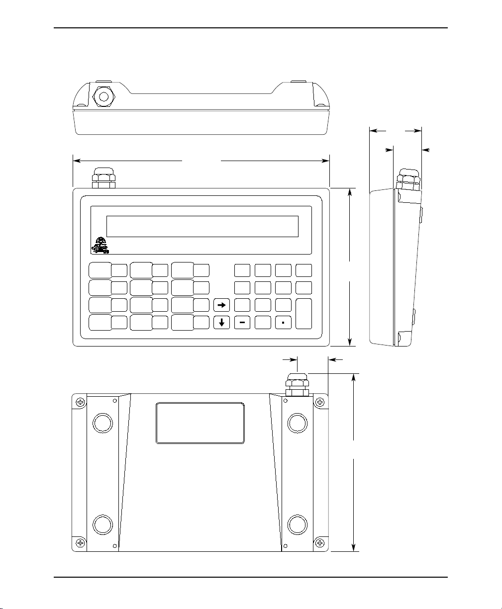
Appendix A (con’t)
Dimensional Outline
1.70
[43]
TOP VIEW
8.12 [206]
0.90
[23]
F4
F10
F1
F7
F2
F5
F8
F3
F6
F9
F12F11
1
2
5
4
8
7
0
FRONT VIEW
CLEAR
3
DELETE
6
E
9
N
T
E
.
R
0.98
5.00
[127]
SIDE VIEW
5.64 MIN
[146]
REAR VIEW
1010-0093, REV 03
Page 18

18 MAP460D
Appendix B
Differences Between MAP460D and MAP460C
Many features were added to make the MAP460 even more capable and easier-to-use. The D uses
the same enclosure, display, keyboard and overlay as the MAP460C, but adds enhancements at a
lower list price.
1. The MAP460D is configured using the Windows-based MAPware-100 or STEPware-100
configuration software.
2. PLC protocols are included in MAPware-100. ASCII protocols are included in
STEPware-100. Protocol PROMS are no longer necessary! Any supported protocol can be
downloaded to the MAP460D using MAPware-100 or STEPware-100.
3. The MAP460D has an internal real-time clock for displaying the time and date in messages.
4. The following software features have been added:
Latched Function Keys- Latched sets a function key coil when pressed and requires that the
•
PLC clear the coil.
• Retentive Function Keys Feature - the function keys retain their last known state during
loss of power to the OIT.
• 10 Register Monitors per message line - Each message line can contain up to 10 register
monitors (only 4 were previously available).
• Extended Character Set - Each message line can display characters from an extended character set that includes some symbols and foreign characters.
• Blinking Text - Each message line can include blinking text or register monitors to highlight important information.
• The Current Message Register informs the PLC of the message line last displayed on the
OIT.
•
Automatic Startup Message - Any message line can be configured as the ‘startup’ message
to be displayed whenever the OIT is reinitialized or powered up.
•
The Signed, Decimal, 4-Digit BCD, 8-Digit BCD, Long, 1/0-binary, On/Off coils, Bank8,
and Bank16 register monitor formats are now available for all PLC protocols.
•
ASCII Format - a new register monitor format displays PLC coils using any ASCII charac
ter string. In addition to On/Off (the only ASCII strings available on the MAP460C) the
460D allows 30 user defined ASCII character strings. Examples are Up/Down or For
ward/Reverse.
•
New Register Monitor Attributes - programmable decimal point; programmable field
width; left or right justification; optional comma insertion; optional leading zeros on Deci
mal, 4-Digit BCD, and 8-Digit BCD formats; linear scaling on Long, Signed,and Decimal
formats; and ‘Hide Data’ format for secure data entry.
5. Local setup mode can be entered by pressing the Enter key three times instead of using a
three key ‘secret’ access.
6. The MAP460D has passed strenuous tests for noise immunity and emissions.
-
-
-
1010-0093, REV 03
Page 19

INSTALLATION MANUAL 19
Appendix B
(continued)
7. New PLC Protocols supported on the MAP460D:
Allen-Bradley MicroLogix 1000
•
Idec Micro³ & Micro³C
•
Keyence KV Series
•
Modicon TSX (MODBUS)
•
Siemens S7-200
•
Telemecanique TSX (MODBUS)
•
8. The communications and power cable are the same as the MAP460C.
Items absent from the MAP460D
1. The MAP460D now uses a non-removable terminal block for both the communications and
power wiring.
2. Local programming (configuring the MAP460’s messages using the MAP460’s keypad) is
no longer supported.
3. The Eagle Signal Micro90 Series protocols is not supported.
1010-0093, REV 03
 Loading...