

Page 1

1010-1001A Rev 02
Page 2

COPY RIGHT NO TICE
This manual is a publication of Maple Systems, Inc., and is provided for use by its customers only. The contents of the
manual are copyrighted by Maple Systems, Inc.; reproduction in whole or in part, for use other than in support of Maple
Systems equipment, is prohibited without the specific written permission of Maple Systems.
WAR RANTY
Maple Systems warrants each product to be free from electrical and mechanical defects in materials and workmanship for a
period of two years from the date of shipment. This warranty does not apply to defects in the Products caused by abuse,
misuse, accident, casualty, alteration, negligence, repair not authorized by Maple Systems, use on current or voltages other
than specified by Maple Systems, or application or installation not in accordance with published instruction manuals. This
warranty is in lieu of any other warranty either expressed or implied.
Maple Systems’ liability is limited to the repair or replacement of the Product only, and not costs of installation, removal, or
damage to user’s property or other liabilities. If Maple Systems is unable to repair or replace a nonconforming Product, it
may offer a refund of the amount paid to Maple Systems for such Product in full satisfaction of its warranty obligation.
Maximum liability of Maple Systems is the cost of the Product.
Information furnished by Maple Systems, Inc., is believed to be accurate and reliable. However, no responsibility is assumed
by Maple Systems for the use of this information nor for any infringements of patents or other rights of third parties which
may result from its use. No license is granted by implication, or otherwise, under any patent or patent rights of Maple
Systems, Inc. Maple Systems retains the right to revise or change its products and documentation at any time without notice.
IF SER VICE IS RE QUIRED
Package the unit in its original packaging container or, if unavailable, any suitable rigid container. If a substitute container is
used, surround the unit with shock absorbing material; damage in shipment is not covered by the warranty. Include a letter
with the unit describing the difficulty and designating a contact person. Send to the following address: Maple Systems, Inc.,
808 134th Street SW, Suite 120, Everett, WA 98204-7333.
Only Products that have been issued a Return Material Authorization (RMA) number from Maple Systems may be returned.
All RMAs must be accompanied with a written purchase order for tracking purposes or, in the case of out-of-warranty
repairs, for repair charges on a time and material basis.
All returns will be tested to verify customer claims of noncompliance with the product warranty. Improper return packaging,
which makes verification impossible, will void the warranty. Products passing the tests will be returned “AS IS” to the
customer.
If noncompliance is verified and is not due to customer abuse or the other exceptions described with product warranty, Maple
Systems will, at its option, repair or replace the Product returned to it, freight prepaid, which fail to comply with the
foregoing warranty, provided Maple Systems is notified of such noncompliance within the two-year warranty period.
AP PLI CA TIONS AS SIS TANCE
This man ual is de signed to pro vide the nec es sary in for ma tion for trou ble-free in stal la tion and op er a tion of your new Op er a tor
In ter face Ter mi nal (OIT). How ever, if you need as sis tance, please call Ma ple Sys tems at 425-745-3229 or visit our web site
at www.ma ple-systems.com.
Page 3

Ta ble of Con tents
EZware Sup port ...................1
OIT Mod els Sup ported ...........1
PLCs Sup ported ................1
About Your Doc u men ta tion .......1
Con ven tions...................1
What You Need ................2
OIT Ba sics .......................2
What is a Sil ver Se ries OIT? .......4
List of Fea tures.................5
Chap ter 1 - In stal la tion of OITs ............7
Be fore You Be gin ..................7
Un pack ing the Unit .............7
Man ag ing Elec tro static Dis charge ...7
CE Com pli ance ................7
NEMA Rat ing ..................7
En vi ron men tal Con sid er ations .....7
Safety Pre cau tions ..............8
Con trol Panel De sign Guide lines ......8
Con trol Panel Ground ing .........9
Con nect OIT Chas sis Ground to
Con trol Panel ..................9
Power Sup ply Se lec tion ..........10
Ca ble Rout ing and Noise Im mu nity . 10
In stal la tion.......................11
Con nect the OIT to Power ........11
Con nect the OIT to the PLC .......12
Panel Prep a ra tion ..............13
Mount the OIT to the Panel .......14
Con fig u ra tion Wir ing ...............14
Con nect the OIT to the PC for
Con fig u ra tion..................15
Fac tory Con fig u ra tion...............15
Chap ter 2 - Cre at ing Your First Pro ject ......17
Be fore You Be gin ..................17
Con nect ing OIT to Com puter .........17
Start ing EZware-500 ...............18
Cre at ing a Sam ple Pro ject ...........19
Set ting the Sys tem Pa ram e ters .....19
Cre at ing a Startup Win dow .......20
Cre at ing a Popup Win dow ........22
Fin ish ing Up......................26
Chap ter 3 - Sim u la tor Mode ..............29
The Sim u la tion Screen ..............29
Trou ble shoot ing Tools Dur ing
Sim u la tion ....................31
Cap tur ing Sim u la tion Screens to Use as
Doc u men ta tion ................31
Wir ing for Nor mal Sim u la tion Mode ....32
Chap ter 4 - Us ing EZware-500 ............35
Over view ........................35
The EasyManager..................35
Com mu ni ca tions Set tings .........36
Op er at ing Modes...............36
The EasyASCIIFontMaker ............37
EasyBuilder’s De fault Text Fonts ....37
Us ing the EasyASCIIFontMaker.....37
The EasyBuilder Ap pli ca tion ..........38
Man ag ing Pro jects ..............39
Print ing Pro jects ................41
Ed it ing and Cre at ing Screen Ob jects 42
Gen eral Set tings ...............58
Se cu rity Set tings Con fig u ra tion.....64
Re start the OIT Au to mat i cally af ter a Pro ject
is Down loaded ....................69
Au to mat i cally Save and Com pile the
Pro ject ..........................69
Com pact Flash ....................69
Con nect ing Mul ti ple OITs to one PLC ...70
Hard ware Con nec tion ..............70
Soft ware Con nec tion ...............71
Shar ing Data Be tween the Mas ter OIT
and Slave OIT .................71
Con nect ing Mul ti ple OITs Us ing the
Ethernet Port ..................72
Shar ing Data Be tween the Mas ter OIT,
Slave OIT and PLC ..............75
Us ing the Aux Port ..............76
Chap ter 5 - Cre at ing Win dows ............79
Win dows Fun da men tals .............79
Open ing a Win dow .............79
Cre at ing a New Win dow .........80
Set ting the Win dow Se cu rity Level .....89
As sign ing Un der lay Win dows ......90
How to Dis play Un der lay Win dows..90
Rules That Ap ply to Un der lay
Win dows .....................90
De let ing a Win dow .............92
Us ing Base Win dows ...............92
How to Dis play Base Win dows .....92
Us ing the Com mon Win dow..........101
Op tional set tings ...............103
Chang ing the Ac tive Com mon
Win dow ......................106
Us ing the Fast Se lec tion Win dow ......108
Us ing the Fast Se lec tion Key.......111
Chang ing screens us ing the Fast
Se lec tion win dow ...............111
Chang ing the Fast Se lec tion Win dow 114
Us ing the Task Bar .................117
Us ing the Win dow Bar ...........118
Gen eral Set tings ...............119
Cre at ing a Mes sage Board ...........120
Op tional Pa ram e ters ............121
Chap ter 6 - Cre at ing Graphic Ob jects .......125
Draw ing Ob jects ..................125
Us ing the Draw ing Tools .........125
Us ing Text ....................128
Pre de fined Shapes and Bitmaps .......129
Us ing a Pre de fined Shape ........130
Page 4

ii Sil ver Se ries In stal la tion & Operation Man ual
Us ing a Pre de fined Bitmap .....131
Graphics Li brar ies .................133
What are ‘states’? ...........134
Us ing Shape Li brar ies ........134
Us ing Bitmap Li brar ies ........142
Us ing Group Li brar ies ........147
Chap ter 7 - Cre at ing and Us ing Da ta bases and
Lan guages ............................153
Cre at ing and Us ing the Tag Li brary ....153
Im port ing and Ex port ing the Tag
Li brary ....................154
Us ing the Tag Li brary .........155
Cre at ing the La bel Li brary ...........155
Im port ing and Ex port ing the La bel
Li brary ....................158
Us ing the La bel Li brary..............158
Us ing Lan guages with the La bel
Li brary ....................160
Chap ter 8 - Rep re sent ing Data with Graphics
Ob jects...............................163
Us ing In ter nal Data Mem ory of OIT ....163
Non-vol a tile Stor age of Sys tem
Pa ram e ters ......................169
PLC Set tings ................169
Gen eral Set tings ............169
Se cu rity Set tings .............170
Rep re sent ing PLC Coil Reg is ters .......170
The Bit Lamp Ob ject ..........170
The Set Bit Ob ject ...........173
The Tog gle Switch Ob ject ......175
Rep re sent ing PLC Data Reg is ters ......177
The Word Lamp Ob ject .......177
The Set Word Ob ject .........179
The MultiState Switch Ob ject ...182
The Nu meric Data Ob ject......184
The Nu meric In put Ex tend Ob ject 187
The ASCII Data Ob ject ........191
The ASCII In put Ex tend Ob ject ..192
The Mov ing Shape Ob ject .....194
The An i ma tion Ob ject ........197
Chap ter 9 - Us ing and Cre at ing Keypads ....201
How to Cre ate a Key pad ............201
Dis play ing and Us ing a Key pad .......204
Us ing the Built-In Nu meric Key pad in
EasyBuilder ................207
Chap ter 10 - Bar Graphs, Me ters, and Trends . 213
Cre at ing Bar Graphs ...............213
Cre at ing Dis play Me ters .............216
Cre at ing Trend Dis plays .............218
Cre at ing XY Plots ..................220
Chap ter 11 - Cap tur ing Alarms and Events ...223
Us ing Alarms .....................223
Mon i tor ing Alarms with the Alarm Scan
Ob ject ..........................223
Dis play ing Alarms us ing the Alarm Dis play
Ob ject ..........................224
Dis play ing Alarms us ing the Alarm Bar
Ob ject ....................228
Us ing Events .....................230
Mon i tor ing Events With the Event Log
Ob ject ....................230
Dis play ing Events Us ing the Event
Dis play Ob ject ..............232
Us ing Events for an Alarm His tory .....234
Us ing the Alarm His tory .......237
Chap ter 12 - Data and Rec ipe Trans fer Ob jects 239
Us ing the Data Trans fer Ob ject .......239
Us ing the Rec ipe Trans fer Ob ject ......240
Cre at ing a Rec ipe............243
Chap ter 13 - Mac ros ....................245
Us ing Mac ros ....................245
Macro Sam ple and
Im ple men ta tion ............245
Vari ables, Dec la ra tions and Mem ory
Us age ..........................248
Mem ory Us age: ............248
Vari able Dec la ra tions.........248
Vari able Ini tial iza tion .........249
Ar ray Ini tial iza tion ...........249
Re served Words .............249
Op er a tor ..................250
Or der of Pre ce dence .........250
Main Func tions and
Sub-func tions...............250
Lo cal and Global Vari ables ....251
Cre at ing Vari able Ar rays ......251
Us ing Mac ros Within Rec i pes ...251
Us ing 32-bit Reg is ters Within
Mac ros....................252
Us ing Float ing Point Reg is ters Within
Mac ros....................253
State ments, Con di tions &
Ex pres sions ................253
Func tion calls and pass ing pa ram e ters
.........................255
Read ing & Writ ing Ex ter nal Reg is ters
in a Macro .................256
Pre cau tions, tips & tricks when us ing
Mac ros ...................257
Com piler Er rors & Er ror Codes ........257
Chap ter 14 - Us ing a Printer With the
HMI530T/550T.........................261
Con fig ur ing the HMI530T/550T for a
Printer ....................261
Print ing a Win dow .................262
Us ing a Func tion Key .........262
Us ing PLC Con trol Ob ject......262
Us ing Sim u la tion Mode .......263
Print ing a Re port ............263
1010-1001a Rev 02
Page 5

Introduction 1
Introduction - Welcome
Welcome to the Maple Systems’ Silver Series of Operator Interface Terminals (OITs). Using graphic OITs has never been
easier. This powerful family of graphics operator interface terminals connects to programmable logic controllers (PLCs) to
provide the human-machine interface in industrial applications. The Silver Series has several features not found in other
graphic OITs. This manual explains the operation of the Silver Series OITs and how to implement the many available
features using the EZware-500 Configuration Software.
EZware Sup port
OIT Models Sup ported
For the latest list of Silver Series Models supported by EZware, please visit our website at http://www.maple-systems.com.
PLCs Supported
For the latest list of PLCs and controllers supported by the Silver Series OITs, please visit our website.
About Your Doc u men ta tion
Maple Systems provides many resources to allow you to get the most out of your Silver Series OIT.
· Silver Series Operation Manual (shipped with EZware-500 as a PDF file) - describes installation, general operation
and features of the Silver Series using EZware-500 configuration software.
· Controller Information Sheets - important information specific to each supported protocol.
· EZware-500 On-line Help - covers the operation of EZware. Always available by clicking Help Topics from the
Help menu in EasyBuilder.
For more information about these and other training sources, visit the Maple Systems web site at:
http://www.maple-systems.com
Con ven tions
When using EZware-500, there are usually several ways to perform a task. For example, if you want to copy a graphics
object, you can:
· Click the Copy command on the Edit menu.
· Click the Copy button on the Standard toolbar.
· Press the CTRL + C keys on your com puter.
1010-1001a, Rev 02
Page 6

2 Sil ver Se ries In stal la tion & Operation Man ual
In most cases, we will describe each method when the task is first discussed. The menu method is then used whenever the
task is used in later procedures. Other conventions used in this book are listed in the following table.
Convention Meaning
Bold
Italic
ALL CAPITALS Directory names, file names, key names, and acronyms
KEY1+KEY2
click Refers to clicking the primary mouse button (usually the left mouse button) once.
Double-click Refers to quickly clicking the primary mouse button (usually the left mouse button) twice.
Right-click
Characters that you must type exactly as they appear. For example, if you are directed to type
a:\setup, you should type all the bold characters exactly as they are printed.
Placeholders for information you must provide. For example, if you are directed to type filename, you
should type the actual name for a file instead of the word shown in italic type. Italics are also used to
indicate a glossary term.
A plus sign (+) between key names means to press and hold down the first key while you press the
second key.
Refers to clicking the secondary mouse button (usually the right mouse button) once. Right-clicking
usually opens shortcut menus.
The following table identifies symbols and margin icons.
Icon Meaning
4 Identifies a procedure.
4 Indicates a reference to additional information.
Indicates an important note.
What You Need
The following items are needed to configure and operate your OIT.
Configuration Software EZware-500
Configuration Cable
(OIT to PC) Y-adapter cable
Personal Computer
Power Cable 6030-0009
24VDC Power Supply
PLC User Provided
Controller Information Sheet
Communication Cable
(OIT to PLC)
1
Al lows you to con nect OIT to PC us ing RS232 and a PLC that uses RS485 at the same time
2
Computer requirements include at least a Pentium 90Mhz PC, 16MB RAM, 10MB available hard disk space, VGA video
2
1
3
7431-0098
User Provided
User Provided (for details refer to Appendix A: Specifications)
Maple Systems provides Controller Information Sheets which contain important information specific
to each PLC. Please locate the sheet that corresponds to your PLC on our website.
Refer to Maple Systems’ Tech Note 1061 for a list of available cables or build your own using the
cable diagrams available on our web site (www. maple-systems.com).
controller, Microsoft Windows 95, 98, 2000, or NT, and one available RS-232 serial port.
3
12-24 VDC power supply needed for the HMI504T.
OIT Ba sics
Operator Interface Terminals (OITs) provide much more versatility than traditional mechanical control panels. An OIT
allows a plant floor operator to monitor current conditions of a control system and, if necessary, to initiate a change in the
operation of the system. OITs connect to programmable logic controllers (PLCs) typically through the PLC’s serial
communications port. The OIT can be programmed to monitor and/or change current values stored in the data memory of the
PLC.
OITs can have either text-based or graphics-based displays. A text-based OIT can display printable text characters but no
graphics. Some text-based OITs can display text characters in various sizes. A graphics-based OIT can display printable text
1010-1001a, Rev 02
Page 7

Introduction 3
characters of varying fonts and sizes and graphics shapes such as icons, bitmaps, or pictures. Using pictures instead of words
or characters often greatly simplifies the operation of the OIT, making the OIT much more intuitive to use.
Some OITs use touch screen displays while others use a membrane-style keypad. Membrane-style keyboards are best used in
applications in which the keypad is likely to become dirty. Touch screen displays are placed over the OIT screen thus
providing much more flexibility than typical membrane-style keypads. Because of this, switches can be created on a touch
screen that appear only when needed.
The Maple Systems Silver Series OITs are graphics-based touch screen OITs. Before we get any further into the operation of
these OITs, it is necessary to define some terms that will be used throughout this manual.
Projects
The OIT has two basic segments of internal memory. The code memory contains the information required by the OIT that
controls how it operates such as the features supported and how it communicates to a PLC. The OIT programmer does not
have the ability to change code memory. The project memory pertains to all of the window screens created and any other
features that the OIT programmer can create using the EZware-500 configuration software. Therefore, the term project is
used to designate the file that is sent to the OIT from the EZware-500 software.
Objects
An object is any action that the OIT performs while it is communicating to the PLC. In order to get the operator interface
terminal to ‘do anything’, you must program the OIT with objects. Objects perform actions such as display text or graphics,
write a value to a PLC register, or display an alarm. Objects most often are graphics shapes that are to be displayed on the
OIT screen. For example, a Text Object is used to display text on the OIT. But objects are also used to configure the OIT to
perform some action. For example, a PLC Control Object tells the OIT to continuously monitor a PLC register that is used
by the PLC to request a new window. Some objects can display a graphics shape on the OIT screen and perform some
action. For example, a Toggle Switch Object creates a graphic object on the OIT that when pressed, activates a bit in the
PLC.
Graphics Object
A graphics object is any text, icon, or picture that can be displayed on the OIT. Graphics objects are further defined by how
they are composed or created. A Text Object is a graphics object that displays text on the OIT screen. A Bitmap Object is a
graphics object that displays a bitmap on the OIT screen. Bitmaps are files stored in the OIT to display pictures. A Shape
Object is a graphics object that displays a shape on the OIT screen. Shapes are also files stored in the OIT to display
pictures. Shapes differ from bitmaps in that shapes are stored using a vector-based file format whereas bitmaps use a
pixel-based file format. Each format has its advantages and disadvantages. We will not go into any more detail about bitmap
objects and shape objects until later in this manual. For now, think of them as objects used to display pictures on the OIT
screen. Finally, a Group Object is the most complex type of graphics object. It is a combination of other objects. Briefly, a
group object consists of one or more objects that are ‘grouped’ together and stored as one object. A good example is a
keypad, which is really a combination of several keys each designed to perform a specific task. When grouped together, a
keypad can be stored as a group object for use in other projects or windows.
Windows
A window is a screen that can be displayed on the OIT. Windows can be full-sized to completely cover the OIT display or
partially sized. Any partially sized window is usually referred to as a popup window. Windows can appear on the OIT
display by a request from the PLC or by a press from the touch screen. Windows can be configured to any size. Once a
window is displayed, it can be moved around the OIT display, removed from the display, or minimized to an icon. Windows
can even overlap each other. Each window can display graphics objects and there is no limit to the number of graphics
objects that can be placed on each window. The Silver Series is capable of storing up to 1999 windows , but the actual limit
is determined by the total amount of memory used for the application. A more in-depth discussion of windows is covered in
later chapters. For now, think of windows as screens that can be displayed on the OIT.
1010-1001a, Rev 02
Page 8

4 Sil ver Se ries In stal la tion & Operation Man ual
What is a Sil ver Se ries OIT?
The Silver Series of OITs by Maple Systems are graphics operator interfaces designed to connect to PLCs in an industrial
environment. The displays are covered with a 4-wire analog resistive touch screen designed for harsh industrial
environments. The touch screen uses the latest in touch screen technology enabling the OIT programmer to create switches
that are very fine in resolution. Unlike many other touch screen OITs on the market, the Silver Series is not limited to a fixed
number of cells in which switches can be created. The OIT programmer can create as many switches of varying sizes and
shapes as he wishes, limited only by the total amount of memory available for the project.
Three LED indicators are provided on the face of the Silver Series OIT to provide instant feedback to the OIT operator of the
current operating condition of the OIT.
LED Indicator Purpose
PWR LED (yellow) indicates if power is applied to the OIT
CPU LED (green) indicates if the OIT is operating correctly
COM LED (red) indicates communications activity on PLC port
The Silver Series OIT has two serial ports, which provide a connection to a PLC using RS-232 or
RS-485 communications and an RS-232 connection to a computer for programming. The serial ports also provide the ability
to connect multiple OITs in series to a single PLC port! The two serial ports also provide the ability to use the EZware-500
configuration software in Simulation Mode enabling the OIT programmer to test his project on the PC instead of
downloading the project to the OIT.
The Silver Series is powered using +24VDC. The viewing level of the OIT display can be adjusted using a contrast switch
located on the back of the unit, or using Local Bits LB9091 and LB9092 for Contrast Up/Down. Finally, a reset switch is
provided on the back of the OIT to reinitialize the OIT if an operational failure occurs. The Silver Series is designed for
industrial environments and carries a NEMA 4 rating as well as CE compliance for noise immunity and emissions.
The HMI504T will operate at 12 VDC.
There are currently SEVEN models in the Silver Series.
Model Display size
HMI504T 4.3" 480 x 272
HMI520T 5.6" 320 x 234
HMI520T E
(Enhanced)
HMI530T 7.7" 640 x 480
HMI530TE
(Enhanced)
HMI550H 10.4” 640 x 480
HMI550HE
(Enhanced)
5.6" 320 x 234
7.7" 640 x 480
10.4” 640 x 480
Resolution
(pixels)
LCD Type
256-color
TFT
256-color
TFT
256-color
TFT
256-color
TFT
256-color
TFT
256-color
TFT
256-color
TFT
Brightness
Contrast
(cdm2)
300 400:1 No No
500 150:1 Standard No
500 150:1 Standard Yes
400 250:1 Standard No
400 250:1 Standard Yes
400 300:1 Standard No
400 300:1 Standard Yes
Recipe/RTC
Module
Ethernet &
Compact
Flash
Finally, the Silver Series are powered by a 200 MHz Intel XScale processor, making it one of the fastest OITs available on
the market. Even the most complicated graphics can be displayed quickly on the OIT screen. In addition, the OIT uses a
proprietary algorithm to find the most efficient means of extracting data from the PLC. This lowers the amount of
‘bottleneck’ time due to the relatively slow communications baud rate of most PLCs. Therefore, the update rate to gather
information from the PLC is very fast.
1010-1001a, Rev 02
Page 9
Introduction 5
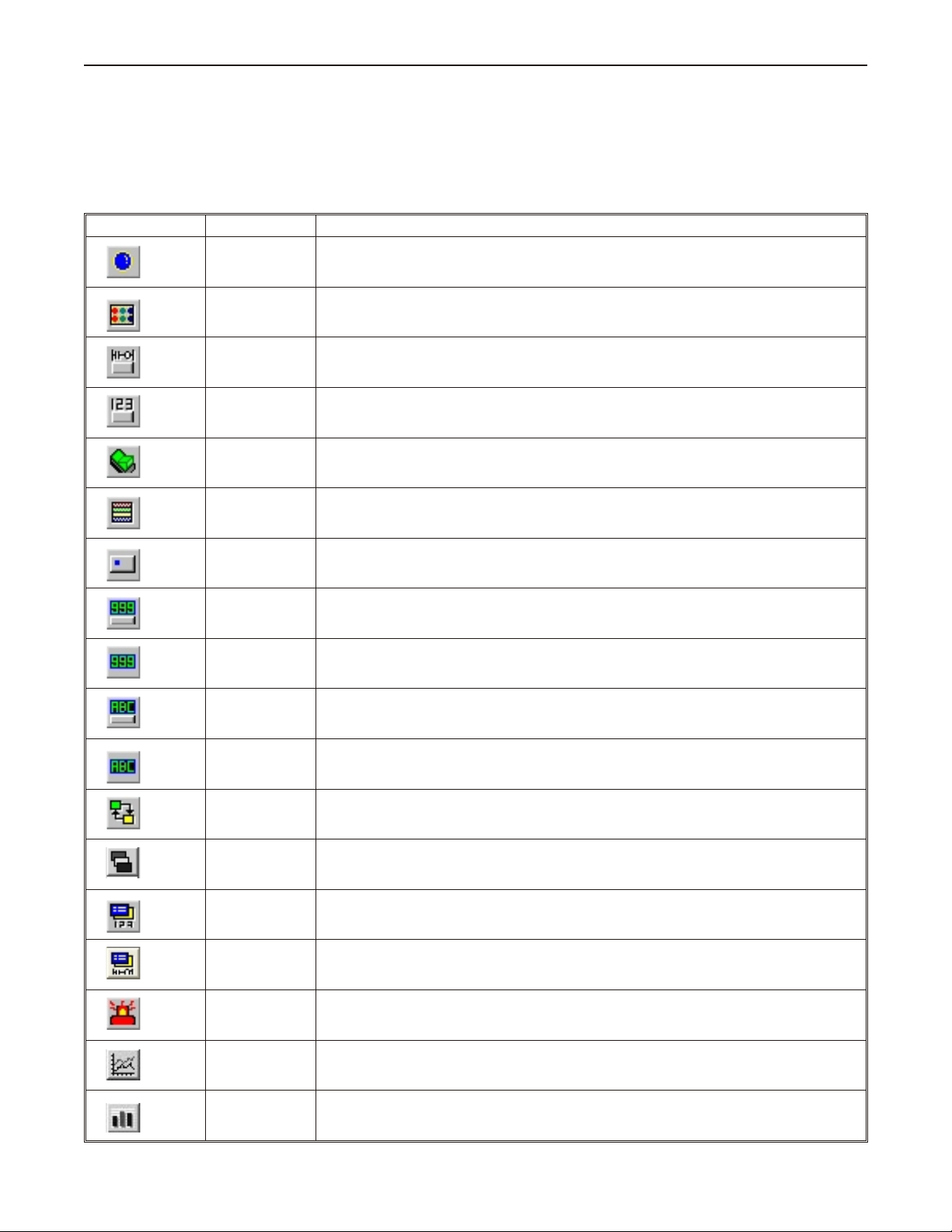
List of Fea tures
The next chapter will guide you through the creation of your first project. Before you proceed, you may wish to read this
brief list of some of the features offered in the Silver Series OIT.
Icon Name Description
Bit Lamp Creates a graphics object to reflect the current status of a PLC bit.
Word Lamp Creates a graphics object to reflect the current state of a multi-state PLC data register.
Creates a touch screen graphics object that represents a two-state switch. When pressed it
Set Bit
sets/resets a PLC bit.
Set Word
Toggle Switch
Multi-State
Switch
Function Key Creates a touch screen graphics object, which displays a window or edits a PLC register.
Numeric Input
Numeric Data Displays a number stored in a PLC register
ASCII Input
ASCII Data Displays ASCII characters stored in a PLC register
Moving Shapes
Creates a touch screen graphics object that represents a multi-state switch. When pressed it
can place a constant value in a PLC register or jog the value.
Creates a touch screen graphics object that represents a two-state switch changing state
(picture) based upon a PLC bit. When pressed, it can control another PLC bit.
Creates a multi-state touch screen graphics object that changes state (picture) according to the
value in a PLC data register. When pressed, it sends a value(s) to another PLC register.
Displays a number stored in a PLC register. The number can be changed using a numeric
keypad.
Displays ASCII characters stored in a PLC register. Characters can be changed using an
alphanumeric keypad.
Creates a multi-state graphics object, which changes state (picture) and position on the screen
according to a value in a PLC register.
Animation
Indirect Window
Direct Window Displays a Window based on a bit in a PLC Register
Alarm Displays Creates alarms to display alarms sent from the Alarm Scan Object
Trend Displays
Bar Graph
Displays
Creates a multi-state graphics object, which changes state (picture) on the screen according to a
value in a PLC register. The positions on the screen are predefined.
Configures the OIT to monitor PLC data registers or coils to display for a specific window popup
by a PLC word address
Creates a trend graph. Samples data in a single or multiple 16-bit PLC register and plots the
data on a time graph
Creates a bar graph with alarm monitoring
1010-1001a, Rev 02
Page 10
6 Sil ver Se ries In stal la tion & Operation Man ual
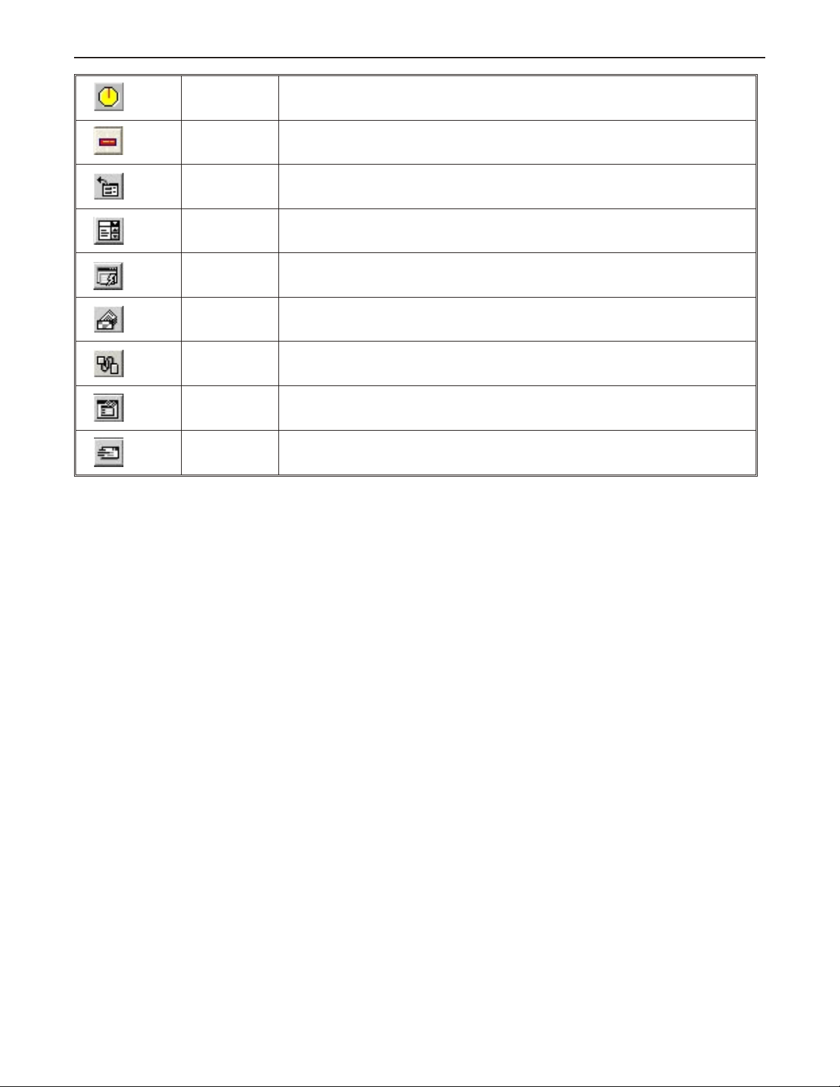
Meter Displays Creates a scale meter
Alarm Bar Displays alarms detected by the Alarm Scan Object on a single horizontal scrolling line.
Recipe Transfer
Event Displays Displays messages according to ‘events’ that occur in the PLC
Alarm Scan Contains the data for detecting alarm conditions.
System
Message
PLC Control Configures the OIT to monitor PLC data registers to display full window screens.
Event Log Monitors and records assigned events
Data Transfer
Transfers data to the specified PLC registers (Note: Recipes are not supported by the
HMI504T).
Customizes the content of system-generated messages.
Configures the OIT to periodically transfer data stored in one set of registers to another set of
registers in the OIT or PLC.
1010-1001a, Rev 02
Page 11

In stal la tion of OITs 7
Chapter 1 - Installation of OITs
Be fore You Be gin
Please read the following for proper handling of your new OIT.
Un packing the Unit
Carefully unpack the OIT. Please read any instructions or cautions that appear on the shipping container. Check all
material in the container against the enclosed packing list. Maple Systems, Inc. will not accept responsibility for
shortages against the packing list unless notified within 30 days. The equipment and its accessories were inspected
and tested by Maple Systems before shipment; all of the equipment should be in good working order. Examine the
equipment carefully; if any shipping damage is evident, notify the carrier immediately. You are responsible for
claim negotiations with the carrier. Save the shipping container and packing material in case the equipment needs to
be stored, returned to Maple Systems, or transported for any reason.
Man aging Elec tro static Dis charge
It is best NOT to remove the rear enclosure of the OIT. When the rear part of the enclosure is removed, the circuitry
inside is exposed to possible damage by electrostatic discharge during handling. Minimize the possibility of
electrostatic discharge by:
· Discharging personal static by grounding yourself prior to handling the OIT
· Handling the OIT at a static-free grounded workstation
· Connecting the frame ground ( ) connector of the OIT to a clean earth ground
· Placing the OIT in an anti-static bag during transport
CE Com pli ance
The Silver Series OITs have been tested to conform to European CE requirements per Council Directive
89/336/EEC. The European Union created these requirements to ensure conformity among products traded in those
countries. Specifically, the Silver Series OITs meet or exceed the noise emissions and immunity requirements as set
forth in the EN50081 (Emissions) and EN50082 (Immunity) standards. These products are designed to withstand
electrical noise in harsh industrial environments. They also conform to requirements that limit electrical emissions.
However, this does not guarantee that the products will be totally immune from possible malfunction in cases where
severe electrical noise occurs. Therefore, we strongly recommend that you follow the guidelines outlined in this
chapter for proper wire routing and grounding to insure the proper operation of the Silver Series OIT.
NEMA Rat ing
The Silver Series OITs are rated for NEMA 4/12 (indoor) or IP65 installations. This means that when the OIT is
properly mounted to a panel or other enclosure, the front enclosure of the OIT will provide protection to the inside
of the panel from splashing water, wind blown dust, rain, or hose-directed water. The OIT must be installed
according to the instructions in this chapter to be properly sealed.
En vi ron men tal Con sid er ations
The Silver Series is designed to operate in temperatures from 0-45° C. It is intended for indoor installations and not
designed for outdoor applications. Avoid installing the Silver Series in environments with severe mechanical
vibration or shocks. Do not install the OIT in enclosures with rapid temperature variations or high humidity. Either
will cause condensation of water inside the device and eventual damage to the OIT.
1010-1001a, Rev 02
Page 12
8 Silver Series Installation & Operation Manual
Safety Precautions
Please observe the following precautions when installing the Silver Series OIT. Failure to comply with these
restrictions could result in loss of life, serious personal injury, or equipment damage.
Warning: Do not operate the OIT in areas subject to explosion due to flammable gases,
vapors, or dusts.
Warning: Do not connect the OIT to an AC power source. You will cause permanent damage
to the OIT.
Warning: Do not attempt to use a DC power supply that does not meet OIT power
requirements. You may cause malfunction or permanent damage to the OIT.
Warning: Do not power the OIT with a DC power supply used for inductive loads or for input
circuitry to the programmable logic controller. Severe voltage spikes caused by these devices may
damage the OIT.
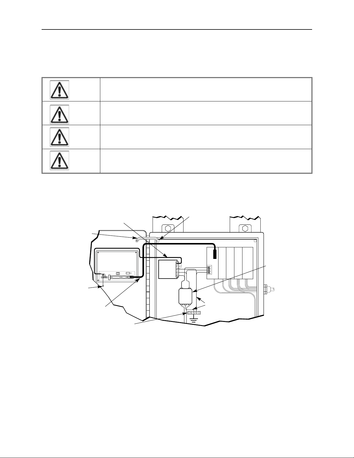
Control Panel Design Guidelines
Pay careful attention to the placement of system components and associated cable routing. These items can
significantly enhance the performance and integrity of your control application.
Control panel is
Shielded power cable
Ground
strap
HMI530
(rear side)
PRINTER
24V
GND
OIT is
grounded to
control panel
Shielded
communication
cable
Quietground
OIT
PC[RS-232]
PLC[RS-485]
PLC[RS-232]
Power
Supply
Control Panel Example
tied to a reliable
earth ground
Line
Filter
PLC/Host
I / O control lines
Ground wires
Quiet ground
(isolated)
Power
line
filter
1010-1001a, Rev 02
Page 13
In stal la tion of OITs 9
HMI530
(rear side)
24V
GND
PLC [RS-485]
PRINTER
PC [RS-232]
PLC [RS-232]
Stud or screw
Control panel
(connected to
earth ground)
Area on panel
free of paint
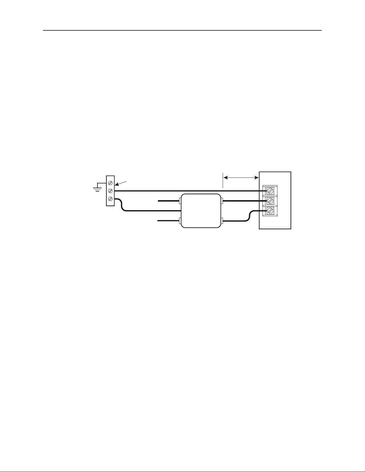
Con trol Panel Grounding
The control panel should be connected to a good, high-integrity earth ground both for safety considerations and
shielding purposes. Maple Systems cannot overemphasize the importance of good grounding. If you fail to use
good grounding procedures during installation, sporadic malfunction of the OIT may occur:
· Connect the OIT’s chassis ground terminal to a reliable earth ground with a low-resistance path.
· Route all earth ground wires that lead from the OIT, the PLC, the power supply, and the line filter to a
central earth ground point such as a barrier strip. This will ensure that no ground current from one device
influences the operation of the other devices.
· Connect the OIT chassis ground terminal to the control panel door using a heavy-gauge short braided cable
or ground wire to minimize resistance.
· Connect the power cable’s shield wire to the OIT’s chassis ground terminal.
· Connect the control panel to earth ground using a copper grounding rod close to the OIT and control panel.
Hinged doors on control panels do not provide a long-term electrical connection to the rest of the enclosure.
Corrosion develops over time and prevents good electrical contract. For this reason, a separate wire braid should be
installed from the hinged control panel to the rest of the enclosure.
For a more in-depth overview of ground wiring techniques, refer to technical note #1027, “OIT Ground Wiring and
Electrical Noise Reduction,” which you can find on our website .
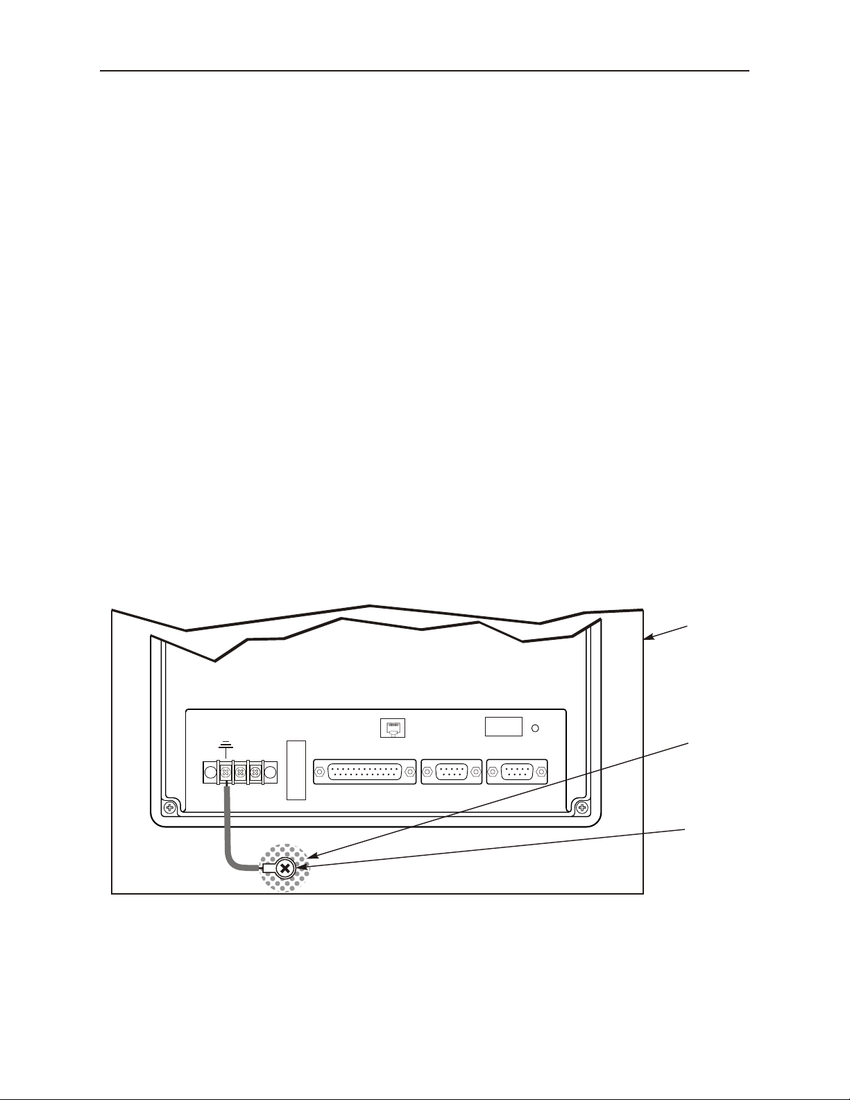
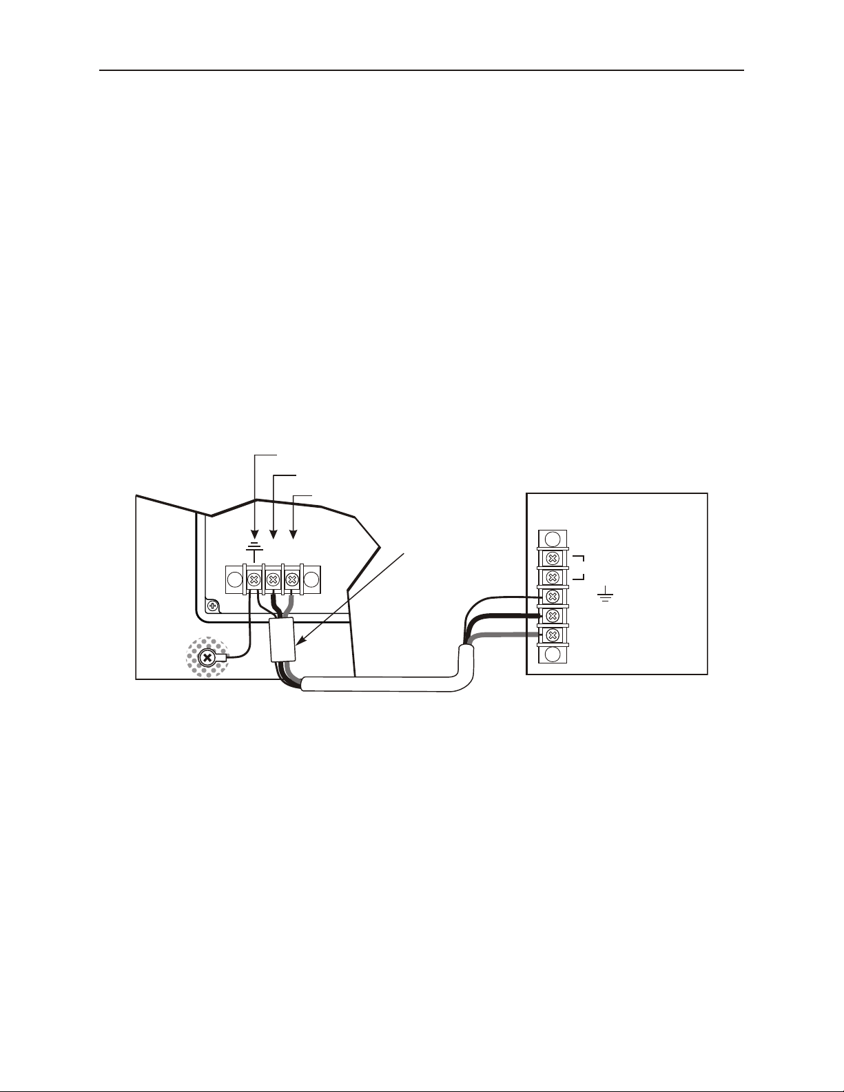
Con nect OIT Chas sis Ground to Con trol Panel
To reduce the possibility of electrical interference, connect the chassis ground terminal of the OIT to a clean earth
ground. If the control panel is metal, make sure it is properly grounded. Then connect a short heavy-gauge wire
(#18 AWG) from the chassis ground terminal of the OIT to a mounting bolt on the control panel door. The
mounting bolt must have good electrical contact to the control panel; scrape away any paint that may be covering
the panel to provide a good connection.
If the control panel is made of a non-conductive material, it is essential that you connect the chassis ground terminal
of the OIT to a clean earth ground point located close to the panel.
OIT Chas sis Ground Con nec tion
1010-1001a, Rev 02
Page 14
10 Sil ver Se ries In stal la tion & Op er a tion Man ual
AC
AC
GND
N
L
White
Black
N
L
G
AC
Line Filter
Green
White to
110Vac neutral
Black to
110Vac load (hot)
To earth
ground
"Quiet”
ground
Bus bar
Power
Supply
Keep short
Power Sup ply Se lec tion
The power supply used to power the OIT should provide an output of +24 VDC 5% measured at the OIT power
terminal block. A 24VDC regulated power supply dedicated to the OIT is required. Refer to the installation guide
that accopanies each OIT for input current requirements.
The power cable for the OIT should be 18AWG, 2-conductor wire with a shield drain wire and protective shield
(foil or braid). The shield drain wire must be connected to earth ground at both ends of the cable. Please refer to the
“Connect the OIT to Power” section for more information.
A power line filter installed at the AC input to the OIT power supply is highly recommended as a safeguard against
conducted RF noise, which is often present on factory power lines. The wires connecting the output of the power
line filter to the power supply should be kept as short as possible to minimize any additional noise pickup. The case
of the power line filter should be connected to a quiet earth ground. The power line filter should have a current
rating of at least 3 Amps with common mode and differential mode attenuation.
Do not use the power supply used to provide power to the OIT to power switching relays, solenoids, or other active
devices.
Ca ble Routing and Noise Im mu nity
Follow these guidelines when routing cable to the OIT:
· Always route the OIT communication cable and the power cable away from any AC voltage or rapidly
switching DC control lines.
· Never bundle the OIT cables together with 120VAC power wires or with relay wiring.
· Try to keep at least 8 inches (20 cm) of separation between the OIT cables and other power wiring. If
voltages greater than 120VAC are used in the system, greater separation is required.
· If the OIT cables must come near AC wiring, make sure they cross at 90 degrees.
· Run AC power wires in a separate grounded conduit to reduce electrical noise interference.
· Keep the cable lengths for the OIT as short as possible. Do not coil excess cable and place it next to AC
powered equipment.
· Cover any equipment used in the enclosure that operates at high frequency or high current levels with a
grounded metal shield.
1010-1001a, Rev 02
Power Line Fil ter Connection
Page 15
In stal la tion of OITs 11
OIT
(rear side)
24Vdc
power supply
Control
panel
Shield wire (bare)
Black wire (-)
Red wire (+)
Ferrite coil
24V
120Vac
Black
Shield drain
Red
FG
DC Output -V (Gnd)
DC Output +V (+24V)
(+)
GND
(-)
In stal la tion
It is necessary to follow all installation procedures described in this chapter for electrical noise immunity and CE
compliance.
Your Maple Systems OIT is designed to connect easily to your PLC. External rear connectors provide quick
connections for power, communications and programming wiring.
There are two serial ports on the rear of the OIT (except the HMI504T, which has one serial port). Both of these are
D-subminiature 9-pin connectors. Use the female connector for RS-232 communications to a PLC. Use the male
connector for RS-485 communication to a PLC and RS-232 communications to a PC.
Use the supplied separate 3-position terminal block to provide power to the OIT.
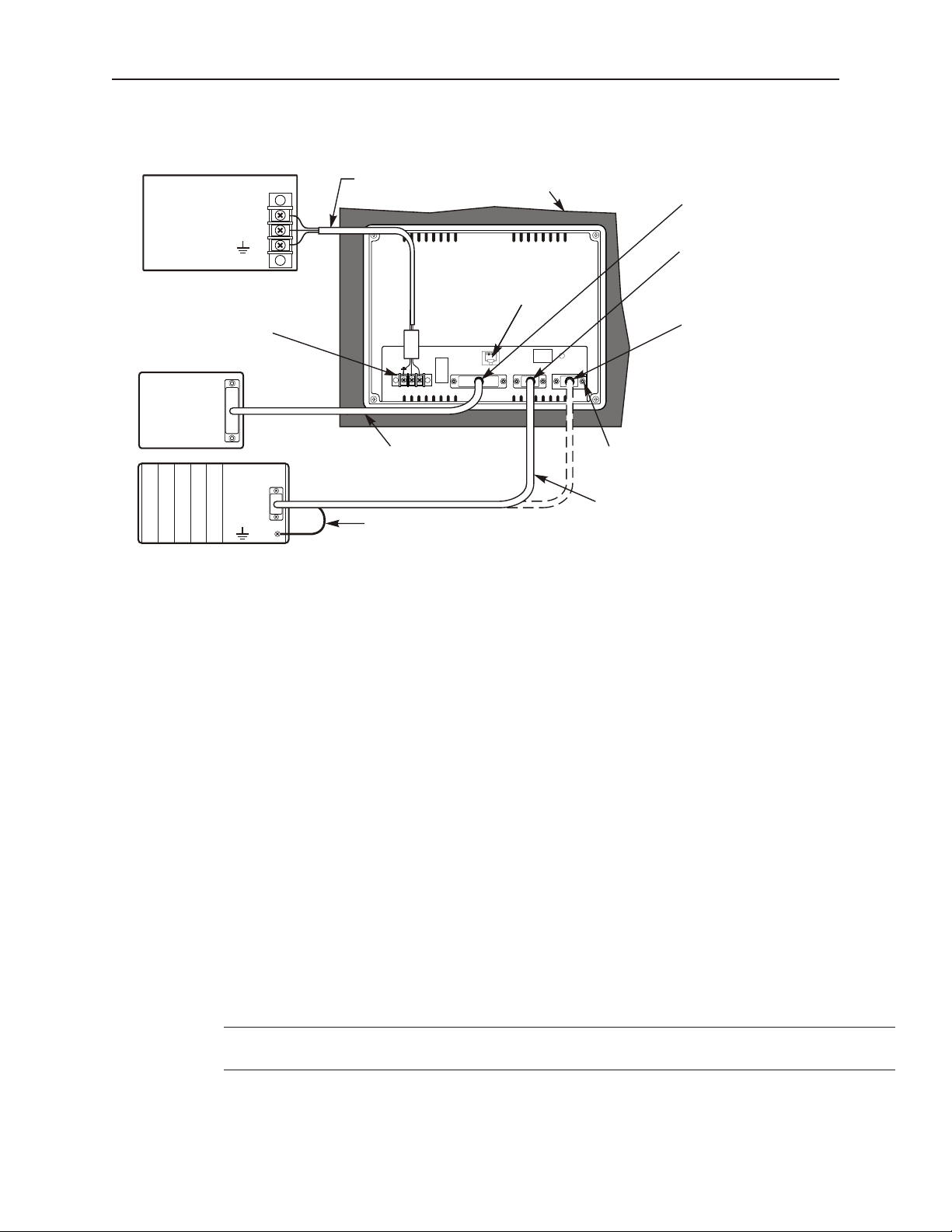
Con nect the OIT to Power
The power cable for the OIT should be 18AWG, 2-conductor wire with a shield drain wire and protective shield
foil. You may buy cable P/N 6030-0009 by the foot from Maple Systems to make these.
Always run the DC ground wire directly back to the signal return of the power supply. Do not use the chassis
ground wire as your signal return! Maple Systems recommends using an axial ferrite coil (Maple p/n 2531-0001)
with each HMI550 OIT to further reduce the electrical interference that may be conducted on the power lines.
Thread the positive and negative wires of the power cable through the ferrite coil so that the coil is no more than two
inches from the OIT’s power input.
4To connect the OIT to power:
1. Connect the power cable to the OIT
a. Strip the power cable shield to expose 2” of the black and red wires.
b. Strip about ¼” of insulation from the black and red wires.
c. Thread the black and red wires through the ferrite core. The shield wire must be outside.
d. Connect the red wire to the DC positive (+) input of the OIT power terminal.
e. Connect the black wire to the DC negative (-) input of the OIT power terminal.
f. Connect the power cable shield wire to the OIT power terminal’s chassis ground input.
2. Route the power cable to the OIT power supply. The power cable should not be any longer
than necessary.
3. Install the power supply wires as follows (with colors shown for Maple Systems cable P/N
6030-0009):
OIT Power Inputs
1010-1001a, Rev 02
Page 16

12 Silver Series Installation & Operation Manual
Color Power Supply HMI504T HMI520T HMI530T HMI550T
Red +Output/+24 Vdc + + 24V 24V +DC24V
Black -Output/+24 Vdc return - GND GND -DC 24V
Shield Case ground FG
The power connector on the Silver Series is a terminal block with wire clamps. Lugs
are not required.
Connect the OIT to the PLC
Each PLC supported by Maple Systems has its own wiring requirements. Maple Systems offers OIT-to-PLC
communication cables for most PLCs that are built to any length and tested for high reliability. Most cables are
available for next-day shipment from Maple Systems. Components and instructions necessary to construct your
own OIT-to-PLC communications cables are also available. Refer to Maple Systems’ Technical Note 1061 or visit
our Web site.
HMI520T/530T/550T HMI504T
Port 1
PLC (RS-232)
Pin # Function Function Function
1 Aux-TXD RXD- RXD-
2 TXD RXD+ RXD+
3 RXD TXD- TXD-
4 (no connection) TXD+ TXD+
5 GND GND GND
6 Aux-RXD (no connection) TXD (PLC)
7 (no connection) TXD TXD (PC)
8 (no connection) RXD RXD (PC)
9 (no connection) (no connection) RXD (PLC)
PLC (RS485) / PC (RS232)
Port 2
Pinout for the OIT Ports
1010-1001a, Rev 02
Page 17
In stal la tion of OITs 13
Shielded Power Cable,
Maple P/N 6030-0009
HMI530
24V
GND
PLC [RS-485]
PRINTER
PC [RS-232]
PLC [RS-232]
OIT
Power Supply
Output
FG
DC Output -V (Gnd)
DC Output +V (+24V)
Enhanced
models only
Enhanced
models only
Attach earth ground wire
(if included on cable)
Printer port
Power connector
Port 1, PLC[RS-232],
has a shielded female
DE9S connector
Port 2, PLC[RS-485]/
PC[RS-232],
has a shielded male
DE9P connector
Communication cable specific for
the PLC/Host; twisted pair, foil
shielded, 28AWG minimum
PLC/
Host
Printer
(Epson
Compatible)
Tighten all screws
Standard
printer cable
Port 1
Port 2
Earth
GND
Control
Panel
STEPS:
Panel Prep a ra tion
A metal panel or mounting surface with a minimum thickness of 15 gauge (0.059 inch/3.3mm) if cold-rolled steel or
hardened steel, or 10 gauge (0.101 inch/2.6mm) if aluminum alloy (6061-T6 preferred) is required. Thinner panels
or surfaces may bow between the mounting clamps and not form a seal with the gasket.
The area of the panel or mounting surface where the gasket comes into contact must be flat and free of scratches,
pits, and other features that prevent the gasket from sealing properly. If the panel or mounting surface is not
uniform, thick, flat, stiff, or smooth enough, then a sealant such as silicone may be required.
Ex am ple of Wir ing a Sil ver Series OIT to a PLC
1. Connect the “OIT” end of the communication cable into either the RS-232 port or the RS-485 port as
required for your application (OIT housing is marked).
2. Tighten the two cable screws at each end to ensure shield ground path.
3. Route the communication cable to the PLC. Refer to the “OIT Cable Routing” section for more
information.
4. Connect the “PLC” end of the cable to the PLC and tighten the cable screws.
5. Connect the green shield wire from the cable to earth ground ( ) on the PLC. If this wire is not
present, make the ground connection inside the PLC connector.
6. The HMI530T/550T has a printer port and can be connected to an Epson compatible printer.
WARNING: The OIT requires a stiff, flat, smooth mounting surface free of blemishes
to seal properly to NEMA 4.
1010-1001a, Rev 02
Page 18

14 Sil ver Se ries In stal la tion & Op er a tion Man ual
Screw clamp locking
tabs go through the
slots
Tighten all screw clamps until
they are uniformly snug
Ends of screws must not
protrude from the clamp
Screw Clamp Placement Clamps Tightened
Hold the OIT against
the panel until all screw
clamps are in position
PanelPanel
Position 4 screw clamps
(2 each side)
Panel
Clean and deburr the panel cutout before the OIT is installed.
Mount the OIT to the Panel
In stall ing Screws on the OIT
STEPS:
CAUTION: Do not over-tighten the screws beyond snugness, or you may damage the housing.
REINSTALLATION: Because the gasket will take a “set” to the panel, be sure to reinstall the OIT to the same
panel cutout when a NEMA 4 seal is required. For best results, also replace the gasket itself.
Con fig u ra tion Wir ing
The OIT must be configured for a particular protocol before use. The EZware-500 software (used on a PC with
Windows 95 or higher) is used for configuring the OIT. For detailed instructions on installing and using the
software, please refer to the software documentation section of this manual.
1010-1001a, Rev 02
1. Prepare the screw clamps by positioning the metal brackets at the midpoints of the screws. Position the
screws so that the ends don’t protrude from the plastic portions.
2. Set the OIT in the panel cutout and hold it in place until all clamps are in position.
3. Tighten the screw clamps until all are uniformly snug.
Page 19

In stal la tion of OITs 15
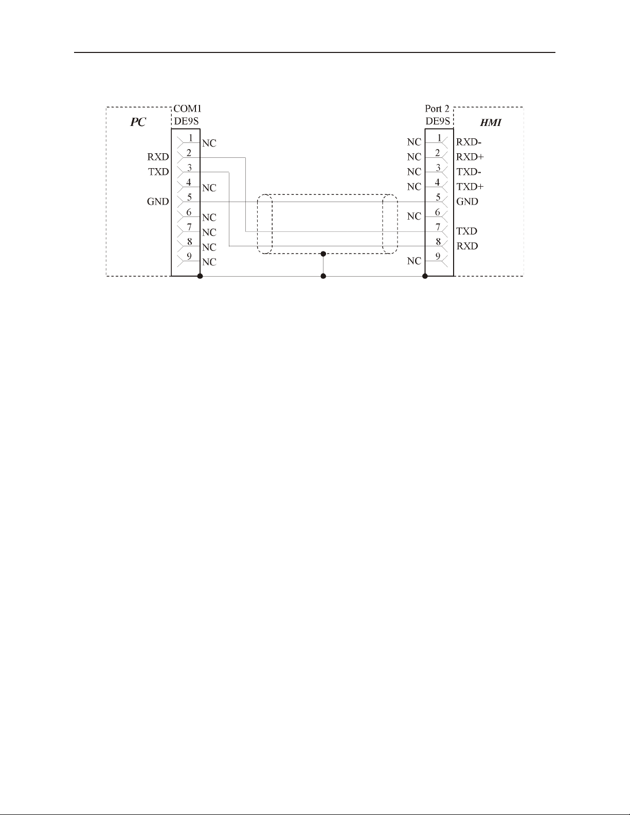
Con nect the OIT to the PC for Con fig u ra tion
To configure the OIT using Maple System’s configuration software, you will need the OIT Configuration Y-adapter
Cable, Maple P/N 7431-0098. Connect the end marked “OIT” into Port 2 on the OIT, marked “PLC[RS-485]/
PC[RS-232], and connect the end marked PC into the proper COM port on your PC. The end marked “PLC” is not
used here. See the figure below for serial port pin assignments and the next two figures for connecting the Silver
series to a PC.
Many PCs no longer support RS232 serial ports. If our PC has a USB port, then you
can download projects using a USB to serial adapter, available at your local
electronics store.
Fac tory Con fig u ra tion
Each OIT arrives from the factory with a demo project file that illustrates some of the most popular features of the
OIT. Please follow the directions enclosed in Chapter 2, Creating Your First Project, to configure your OIT for the
PLC that you are using.
Each OIT has a potentiometer located on the back for adjusting the level of contrast on the display. It is set for
optimum clarity at the factory but you can change the setting if necessary.
The OIT also has a black reset pushbutton and a four position DIP switch located through an access hole on the back
of the enclosure. The reset switch can be used to reinitialize the OIT if the OIT malfunctions. Only Dip switch 1
and 2 have functionality. Dip switch 1 puts the OIT into Touch Calibration mode. Dip switch 2 forces the OIT into
download mode, and needs to be set for downloading from a Compact Flash card. For normal operation, all of the
DIP switches should be set to the OFF position.
The touch screen of the OIT is fully calibrated before it leaves the factory so you shouldn’t need to adjust it.
However, with time the touch screen may need to be recalibrated.
4To calibrate the touch screen
1. Connect the OIT to your computer for programming.
2. From the Start menu, click Programs, then Maple Systems, then EZware-500, then the
EasyManager program.
3. Click Jump To Touch Adjust. The OIT screen should change to calibration mode.
4. After the OIT displays a crosshair cursor, you are prompted to touch the cursor for:
a. Top left position
b. Top right position
c. Bottom left position
d. Bottom right position
5. The OIT screen displays two rectangular objects. To determine whether the touch screen is
properly calibrated, place and hold your finger somewhere on the touch screen other than on
the rectangular spots. The crosshair cursor should appear directly under your finger. If
needed, press the left rectangle to repeat the calibration. Press the right rectangle to end
calibration.
6. Once you have completed calibration, press the touch screen again to return to normal
application mode.
1010-1001a, Rev 02
Page 20
16 Sil ver Se ries In stal la tion & Op er a tion Man ual
OIT to PC Se rial Port Pin As sign ments
1010-1001a, Rev 02
Page 21

Cre ating Your First Project 17
Chapter 2 - Creating Your First Project
Often the best way to learn about new software is to just jump right in. This chapter will step you through the
process of installing the EZware-500 configuration software and then using the software to create a sample project
that can be downloaded to your OIT. We won’t go into much detail as to how each feature works. The purpose of
this chapter is only to provide you with an overview of the process of creating a functional OIT that can
communicate to a PLC. For our sample project, we will configure the OIT using the MemoryMap_Master protocol
but you may feel free to select whichever protocol driver you intend to use.
By the end of this chapter, you should be able to:
· Install EZware-500 configuration software.
· Create a sample project with two windows and several graphics objects.
· Save a project, compile a project and download the project to the OIT.
· Verify that the OIT is functioning properly.
Be fore You Be gin
Before you install EZware-500, make sure your computer meets the following minimum system requirements:
· Pentium-based 90MHz or higher processor
· 16 MB of RAM (more memory improves performance)
· 10 MB available hard disk space
· VGA or higher-resolution monitor set for 256 color 800x600 pixel mode
· Microsoft Mouse or compatible pointing device
· One available RS-232 port
· Microsoft Windows 95, 98, NT, XP or higher
Con necting OIT to Com puter
Before you start your first project, the OIT should be connected to the computer so that the project can be
downloaded after creating it. You should also connect the PLC that you are using to the OIT so that you can test the
operation of the OIT after you have finished creating this sample project.
4To connect your OIT to the computer
1. Connect a +24VDC power supply to the OIT.
2. Connect the Y-adapter programming cable (Maple P/N 7431-0098) to the computer and OIT.
• Con nect the end marked OIT to the OIT port la beled PC[RS-232].
• Con nect the end marked PC to the COM port of the com puter.
3. Apply power to the OIT.
4Changing the PC COM Port used by EZware-500
1. EZware-500 is initially configured to use Com Port 2:
2. In Windows, click the Start button.
3. Select Programs.
4. Select EZware500.
5. Select EasyManager.
6. In the top left drop-down list box, select COM 1.
7. Choose EXIT.
1010-1001a, Rev 02
Page 22

18 Sil ver Se ries In stal la tion & Op er a tion Man ual
4To connect your PLC to the OIT
1. Maple Systems produces PLC communications cables, which will connect the OIT to most of
the PLCs available. The cables can be manufactured to any length you may require. A listing
of all the PLC cables Maple Systems offers can be found on our website.
2. If you have decided to make your own cable, make sure that it is wired correctly for your
particular PLC. Maple Systems provides cable wiring diagrams to guide you through the
construction of your cable. These can also be found on our website.
3. Connect the PLC communications cable from the serial port on your PLC to the appropriate
serial port on your OIT.
• If you are us ing RS-232 com mu ni ca tions, then con nect the OIT end of the ca ble to the OIT
port la beled PLC[RS-232].
• If you are using RS-485 communications, then connect the OIT end of the cable to the OIT
port labeled PLC[RS-485]. If you wish to use the Y-adapter programming cable, then
connect to the cable end that is marked PLC.
4. Apply power to the PLC. The Silver Series OIT is programmed at the factory with a sample
demo that shows some features of the OIT. The OIT should display a sample startup screen.
The OIT will now accept a new project from EZware-500.
Starting EZware-500
Before you can create a sample project, you must start the configuration software. The EZware-500 software has
three main applications:
· EasyBuilder – used to create the project downloaded to the OIT.
· EasyManager - used to place the OIT into different operating modes.
· EasyASCIIFontMaker - used to edit the text fonts that display characters on the OIT.
4To start the EZware-500 software
1. From the Windows Task Bar, click the Start button, point to Programs, and then click the
EZware-500 folder.
2. Click EasyManager to start the EasyManager application.
3. Select the appropriate COM port on your computer.
4. Select a baud rate of 38400.
After you have successfully downloaded a project to the OIT using this baud rate, try
using 115200 to decrease the required download time.
5. Click Project Download/Upload.
6. Click Complete Download/Upload.
After you have downloaded your first project to the OIT, you can switch to Partial
Download/Upload to decrease the required download time.
7. On the EasyManager dialog box, click EasyBuilder.
8. The Welcome to EasyBuilder dialog box appears. Select the correct OIT model.
9. Click OK to display the main screen of EasyBuilder.
If the main screen of EasyBuilder is displayed after you click EasyBuilder from the
EasyManager dialog box, select the correct model of OIT by clicking New from the File
menu.
1010-1001a, Rev 02
Page 23
Creating Your First Project 19
Menu selections
Draw toolbar
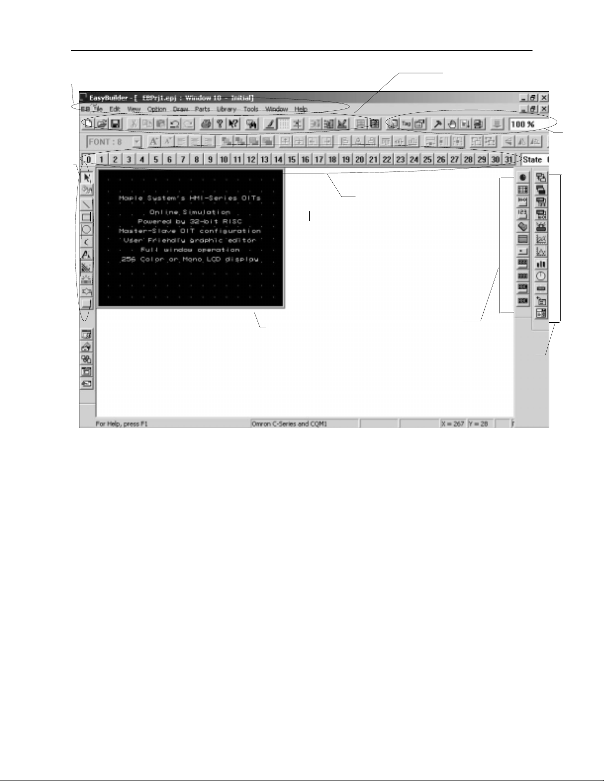
The following illustration shows the various sections of EasyBuilder.
State toolbar
Work area
Standard toolbar
Manager
toolbar
Part1 toolbar
Part2 toolbar
Creating a Sample Project
This section walks you through the creation of an EasyBuilder project named EBPrj1. Once downloaded to the OIT,
this basic configuration allows the OIT to connect to the PLC, display a startup screen, and display a screen
containing one PLC register monitor when a switch on the startup screen is pressed.
Although we strongly recommend that you perform the following steps to create this sample project, the project is
already included in your EasyBuilder software with the following filenames:
HMI504T.EPJ
-sample project for the HMI504T
HMI520T.EPJ
-sample project for the HMI520T
HMI530T.EPJ
-sample project for the HMI530
HMI550T.EPJ
-sample project for the HMI550H
Setting the System Parameters
Whenever you begin a new project, you should always set the system parameters before you create any windows.
System parameters determine the basic operating conditions of the OIT such as what type of PLC it is connecting to.
1010-1001a, Rev 02
Page 24

20 Sil ver Se ries In stal la tion & Op er a tion Man ual
4To edit the System Parameters
1. Click the Edit menu on the main screen of EasyBuilder.
2. At the bottom of the menu, click System Parameters. The Set System Parameters dialog box
appears.
3. The dialog box has six tabs: PLC, General, Indicator, Security, Editor and Hardware. Select
the PLC tab.
4. Select the PLC that you are using or MemoryMap_Master from the PLC type pull-down
box.
5. Select RS485 from the Serial port I/F box.
6. Select 8 bits from the Data bits box.
7. Select 1 bit from the Stop bits box.
8. Select 19200 from the Baud rate box.
9. Select Odd from the Parity box.
10. Select 0 for the OIT station No. and PLC station No. Boxes.
11. Select Disable from the Multiple OIT box.
12. Select 3.0 from the PLC time out constant box.
13. Select 0 from the PLC block pack box.
14. Now click on the General tab.
15. Select 10 for the Startup window No. Box.
16. Click OK to return to the EasyBuilder main screen.
The communications parameters selected above were selected at random. Please enter
the PLC type and communications parameters that match your PLC. For more
information, consult your PLC operations manual or Maple Systems Controller
Information Sheets available on our website at www.maple-systems.com .
Cre ating a Startup Win dow
We will configure Window #10 as the startup screen. The OIT can store up to 1999 predefined windows but
screens 0-9 are reserved. Therefore, the first window screen that is available for configuration is Window #10. By
default, this is the startup screen when you begin a new project. This section will show how to place text in the
window and how to create two function keys that will open and close Window #11.
4To place text on Window#10
1. From the Draw menu, click Text. The Create Text Object dialog box appears.
2. Click the pull down box from the Color box. The Color dialog box appears.
3. Click on the white color box, then click OK. The color box should reflect the color that you
have chosen.
4. Select 16 in the Font box.
5. Select Left in the Align box.
6. Double-click the word ‘text’ in the Content box and type “This is the Startup Screen!.”
7. Click OK.
8. On the main screen of EasyBuilder, you will see a white rectangle outline that is attached to
your cursor in the work area. This represents the text box just created. Center the rectangle
somewhere on the top third portion of the work area and then click. The text box “This is the
Startup Screen!” should appear.
4To create a function key on Window#10
1. From the Parts menu, click Function Key. The Create Function Key Object dialog box
appears.
2. Type On Button in the Description box.
3. Click Popup Window.
4. Type 11 in the Window No. Box.
5. Click the Shape tab.
6. Click Use shape, then click Shape library. The Shape Library dialog box appears.
1010-1001a, Rev 02
Page 25

Cre ating Your First Project 21
7. Click button1 in the Shape library box.
8. Scroll through the selections to selection 23. Click the shape, then click OK. The shape
should appear in the Shape tab.
9. Click the Label tab.
10. Click the pull down box from the Color box. The Color dialog box appears.
11. Click on the black color box, then click OK. The color box should reflect what you have
chosen.
12. Select 16 in the Font box.
13. Select Left in the Align box.
14. Type ON in the Content box.
15. Click the Use Label box.
16. Click OK.
17. On the main screen of EasyBuilder, you will see a white square outline that is attached to your
cursor in the work area. This represents the function key just created. Center the square
somewhere on the bottom left portion of the work area and then click. The function key
should appear.
18. Double-click on the function key. The Function Key Object’s Attribute box appears.
19. Click on the Profile tab.
20. Enter 47 for the X position. Enter 168 for the Y position.
21. Enter 62 for the Width. Enter 49 for the Height.
22. Click OK.
23. On the main screen of EasyBuilder, you should see the function key that you just created
move and/or change size. This function key is used to display Window #11.
4To create a second function key on Window#10
1. We could create the second function key by repeating the steps for the first function key.
Instead, however, we will take advantage of the first function key and copy it.
2. Click the first function key to highlight it.
3. From the Edit menu, click Copy.
4. From the Edit menu, click Paste. A copy of the function key appears in the upper left corner
of the work area. Deselect the function key by clicking on any blank space in the work area.
5. Double-click on the second function key. The Function Key’s Object Attribute dialog box
appears.
6. In the General tab section, change the Description to Off Button.
7. Click on Change Window. Enter 10 for Window number
8. Click on the Label tab. Type OFF in the Content box.
9. Click on the Profile tab.
10. Enter 196 for the X position. Enter 168 for the Y position.
11. Click OK.
12. On the main screen of EasyBuilder, you should see the second function key that you just
created move to the lower right hand side of the work area. This function key is used to close
Window #11.
1010-1001a, Rev 02
Page 26

22 Sil ver Se ries In stal la tion & Op er a tion Man ual
You have finished configuring your first window. It should look something like the picture below:
Cre ating a Popup Win dow
We will configure Window #11 as a popup window. Up to six popup windows can be displayed on a full screen
window. The windows may overlap each other or may be minimized to an icon. This section will show how to
create a scale and a numeric register that displays the current value of the scale. You will also create an increment
and decrement key to change the value in the scale meter.
4To create Window#11
1. From the Window menu, click Open Window. The Open Window dialog box appears.
2. Click New Window. The Select Window Style dialog box appears.
3. Click Base Window. The Window Setting dialog box appears.
4. Enter 79 for the X position. Enter 58 for the Y position.
5. Enter 160 for the Width. Enter 120 for the Height.
6. Click the pull down box from the Background Color box. The Color dialog box appears.
7. Click on the white color box, then click OK. The color box should reflect the color that you
have chosen.
8. Click OK.
9. Select Window_11 in the Open Window dialog box.
10. Click Open. The main screen of EasyBuilder should reappear with Window #11 displayed in
the work area.
4To create a rectangle on Window#11
1. From the Draw menu, click Rectangle. The Attributes dialog box appears.
2. Click on Interior Filled.
3. Click the pull down box from the Interior box. The Color dialog box appears.
4. Click on the white color box, then click OK. The color in the Interior box should reflect the
color that you have chosen.
5. Click on an area somewhere inside Window #11. Create a rectangular shape by moving the
mouse cursor. Click again to permanently create the rectangle.
6. From the Edit menu, click Select.
7. Double-click somewhere on the rectangle. The Rectangle Object’s Attribute dialog box
appears.
8. Click the Profile tab.
9. Enter 48 for the X position. Enter 13 for the Y position.
10. Enter 61 for the Width. Enter 36 for the Height.
11. Click OK.
1010-1001a, Rev 02
Page 27
Cre ating Your First Project 23
12. On the main screen of EasyBuilder, you should see the rectangle that you just created move
and/or change size. This rectangle is used as a backdrop to the scale meter.
4To create scale lines on Window#11
1. From the Draw menu, click Scale.
2. Click on an area somewhere inside Window #11. Create a scale shape by moving the mouse
cursor. Click again to permanently create the scale lines.
3. From the Edit menu, click Select.
4. Double-click somewhere on the scale lines. The Scale Object’s Attribute dialog box appears.
5. In the Scale Style box, click Up.
6. Type 10 in the Division box.
7. Type 8 in the Meter length box.
8. Click on the Profile tab.
9. Enter 51 for the X position. Enter 16 for the Y position.
10. Enter 56 for the Width. Enter 28 for the Height.
11. Click OK.
12. On the main screen of EasyBuilder, you should see the scale that you just created move
and/or change size. This scale should be enclosed by the rectangle.
4To create a meter display on Window#11
1. From the Parts menu, click Meter Display. The Create Meter Display Object dialog box
appears.
2. Type Meter Display in the Description box.
3. Click the Meter Display tab.
4. In the Style 2 Indicator box, click Up half.
5. In the Value Span box, enter 100.
6. Click OK.
7. On the main screen of EasyBuilder, you will see a white square outline that is attached to your
cursor in the work area. This represents the meter display just created. Click to place the
meter display in Window #11.
8. Double-click on the meter display. The Meter Display Object’s Attribute dialog box appears.
9. Click on the Profile tab.
10. Enter 51 for the X position. Enter 16 for the Y position.
11. Enter 56 for the Width. Enter 28 for the Height.
12. Click OK.
1010-1001a, Rev 02
Page 28
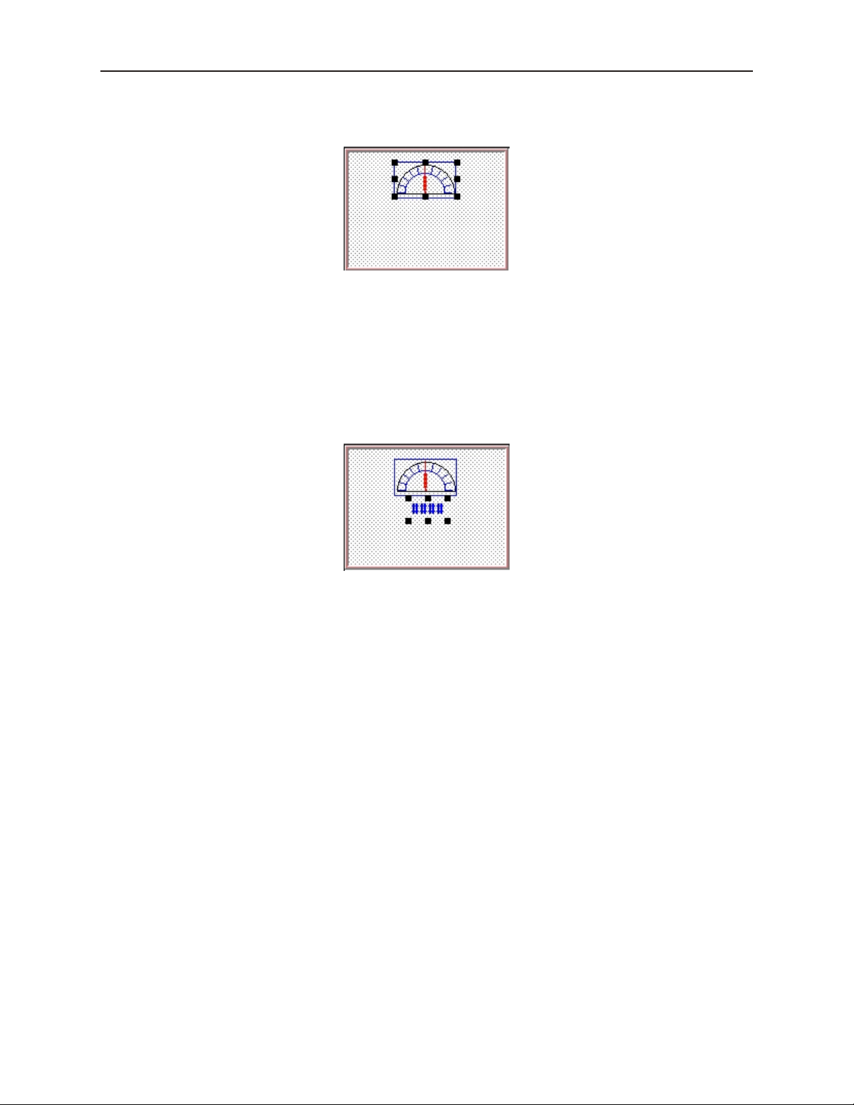
24 Sil ver Se ries In stal la tion & Op er a tion Man ual
13. On the main screen of EasyBuilder, you should see the scaled meter display that you just
created move and/or change size. The scaled meter display is now complete.
4To create a numeric register on Window#11
1. From the Parts menu, click Numeric Data. The Create Numeric Data Object dialog box
appears.
2. Type Numeric Data in the Description box.
3. Click OK.
4. On the main screen of EasyBuilder, you will see a white rectangle outline that is attached to
your cursor in the work area. This represents the numeric register just created. Click to place
the numeric register on Window #11 somewhere underneath the scale meter. Four pound
signs “####” should appear.
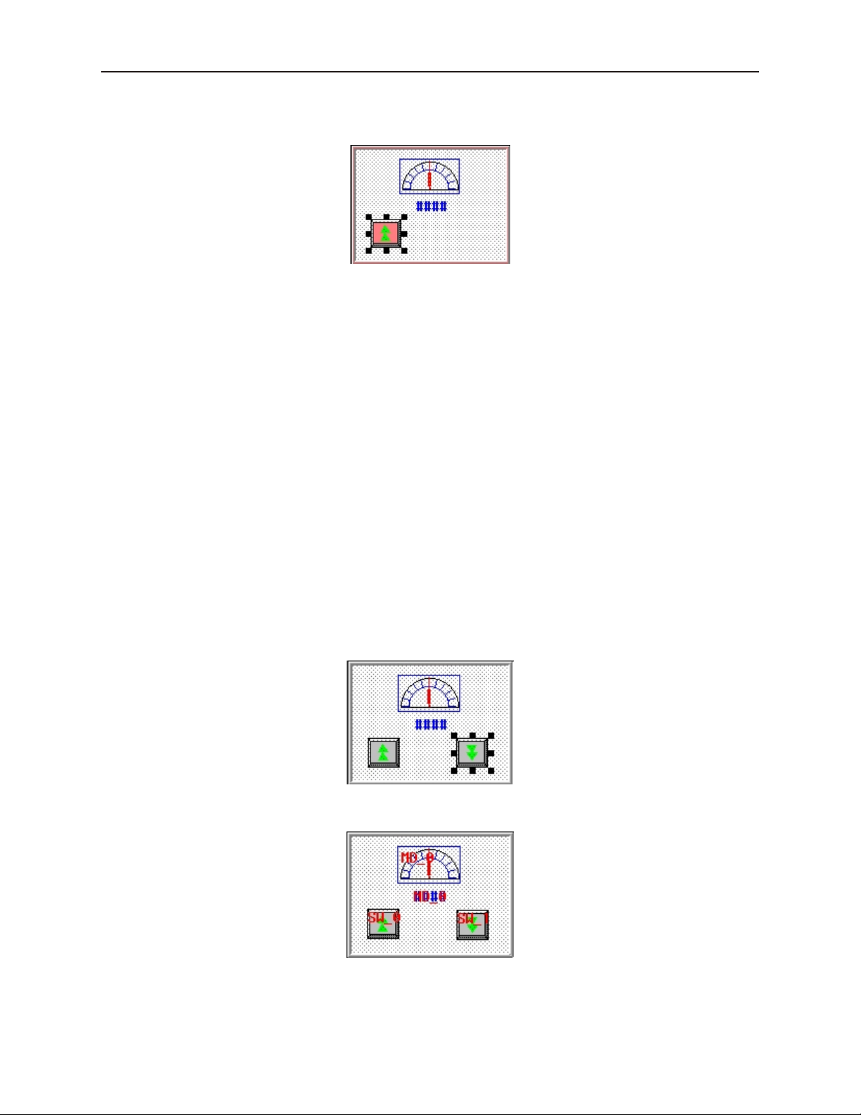
4To create an increment key on Window#11
1. From the Parts menu, click Set Word. The Create Set Word Object dialog box appears.
2. Type Increment Button in the Description box.
3. Click on the pull down box of the Set Style Attribute and select JOG++.
4. Enter 1 in the Inc. value box.
5. Click on the pull down box of JOG Delay and select 0.5 second.
6. Enter 100 in the Attribute Upper limit box.
7. Click the Shape tab.
8. Click Use shape, then click Shape library. The Shape Library dialog box appears.
9. Click Select Lib… The Open dialog box appears.
10. Select button3.slb from the list of shape libraries. Then click Open.
11. Click button3 in the Shape library box.
12. Scroll through the selections to selection 21. Click the shape, then click OK. The shape
should appear in the Shape tab.
13. Click OK.
14. On the main screen of EasyBuilder, you will see a white square outline that is attached to your
cursor in the work area. This represents the increment key just created. Click to place the
increment key on Window #11.
15. Double-click on the increment key. The Set Word Object’s Attribute dialog box appears.
16. Click on the Profile tab.
17. Enter 19 for the X position. Enter 74 for the Y position.
18. Enter 31 for the Width. Enter 29 for the Height and click OK.
1010-1001a, Rev 02
Page 29
Cre ating Your First Project 25
19. On the main screen of EasyBuilder, you should see the increment key that you just created
move and/or change size. The increment key is now complete.
4To create a decrement key on Window#11
1. As with the second function key of Window #10, we are going to create the decrement key by
copying the increment key and then making changes to the attributes.
2. Click the increment key to highlight it.
3. From the Edit menu, click Copy.
4. From the Edit menu, click Paste. A copy of the increment key appears in the upper left
corner of the work area. Deselect the increment key by clicking on any blank space in the
work area.
5. Double-click on the second increment key. The Set Word Object’s Attribute dialog box
appears.
6. In the General tab section, change the Description to Decrement Button.
7. Click on the pull down box of the Set Style Attribute and select JOG—.
8. Enter 0 in the Attribute Bottom limit box.
9. Click the Shape tab.
10. Click Shape library. The Shape Library dialog box appears.
11. Scroll through the selections to selection 22. Click the shape, then click OK. The shape
should appear in the Shape tab.
12. Click on the Profile tab.
13. Enter 105 for the X position. Enter 74 for the Y position.
14. Click OK.
15. On the main screen of EasyBuilder, you should see the decrement key that you just created
move to the lower right hand side of the work area.
The following illustration shows how the popup window looks:
1010-1001a, Rev 02
Page 30

26 Sil ver Se ries In stal la tion & Op er a tion Man ual
You have now done your part in creating this sample project. It is now time for EZware-500 to do its part.
Fin ishing Up
There are still a few steps, which must be completed before you can test your first project. In this section, you will:
· save the project onto your computer hard drive
· compile the project into a format that can be understood by the OIT
· download the project to the OIT
· verify that the OIT operates as expected
· exit the EZware-500 software
If you haven’t already done so, now would be a good time to connect the OIT to the
computer and to connect the PLC that you are using to the OIT. For more information,
consult the first part of this chapter or see “Installation of OITs” later on in this
manual.
4Saving your first project
1. From the File menu, click Save As. The Save As dialog box appears.
2. In the File name text box, type EBPrj1.
3. Click Save. The file is saved onto your computer hard drive and the main screen of
EasyBuilder reappears.
4Compiling your first project
1. From the Tools menu, click Compile. The Compiling dialog box appears.
2. Click Compile. EasyBuilder will compile your project and display error results.
3. If no errors occur, click Close. The main screen of EasyBuilder reappears. If errors have
occurred, repeat the steps in the Creating a Sample Project section.
4Downloading your first project
1. Apply power to your OIT.
2. From the Tools menu, click Download. The EasyDownload Complete Project dialog box
appears.
3. If the OIT is correctly connected to the computer, then the download process will begin. You
will notice that a horizontal bar graph is displayed on the computer indicating how much of
the project has been downloaded. The OIT will also display several Write Flash commands
that scroll on the screen. If a timeout error is displayed, please review your connection of the
OIT to the computer and make sure that the appropriate settings in EasyManager are used.
4. After the download is finished, the Mission Complete dialog box is displayed.
5. Click OK. The main screen of EasyBuilder reappears.
6. You will now use EasyManager to get the OIT to execute the project you just downloaded. If
you want to exit EasyBuilder, from the File menu click Exit.
4Displaying your project on the OIT
1. From the Windows Task Bar, click EasyManager. The EasyManager dialog box appears.
2. Click Jump To Application. This will send a command to the OIT to run the project.
1010-1001a, Rev 02
Page 31

Cre ating Your First Project 27
3. The OIT should display the following screen.
4. Press the ON function key to display the popup window.
5. Press the increment and decrement keys on the OIT to see the value in the data register and
scale meter change. Press the OFF function key to remove the popup window.
CONGRATULATIONS. You have completed your first EZware-500 project.
1010-1001a, Rev 02
Page 32

28 Sil ver Se ries In stal la tion & Op er a tion Man ual
1010-1001a, Rev 02
Page 33

Sim u la tor Mode 29
Chapter 3 - Simulator Mode
As you saw from creating the sample project in the last chapter, downloading any changes you make to the OIT can
take time. To decrease the amount of time required to download a project to the OIT you can make these changes in
EasyManager:
· Select the 115200 baud rate. The default setting of 38400 is recommended for older computers or when
using a very long programming cable.
· Select Partial Download/Upload. The default setting is Complete Download/Upload. A complete
download should be used whenever you receive a later version of EZware-500 or any Boot ROM updates.
It should also be used whenever you select a different PLC protocol driver.
However, even with these improvements, it may still take 1-2 minutes to download a project. A better way of testing
changes made to a project is to use the computer to simulate the operation of the OIT.
This chapter shows you how to dramatically save time when creating and testing a project by putting the computer
into Simulation Mode. In Simulation Mode, the computer displays a screen that simulates what is seen when the
OIT executes the project file. You can use the mouse on your computer to simulate the operation of the touch
screen on the OIT. Rather than waiting two minutes to test each change you make to your project, you can now
instantly switch to Simulation Mode to see if your project is working as expected.
You can enter Simulation Mode in three ways. Using the sample project that you created in the last chapter, we will
guide you through the three methods.
The Sim u la tion Screen
All modes of simulation use the same screen.
For our example, we are showing the sample project as it would appear after the ON function key has been pressed.
When the Simulation Mode screen first appears, it will always show the startup screen of the project. You can test
any objects you have created which require touch screen input by clicking on them. In this example, clicking on the
increment key simulates the key as it is pressed on the touch screen. Simulation Mode always uses the compiled
version of the project that you have created (the *.eob file). Therefore, you must save and compile any changes you
make to the project before you can simulate it.
Simulating the OIT is done in on-line or off-line mode. On-line simulation has two modes:
1010-1001a, Rev 02
Page 34

30 Sil ver Se ries In stal la tion & Op er a tion Man ual
‘Normal’ mode requires that the OIT be connected to the computer and that the PLC be connected to the OIT.
‘Direct’ mode requires only that the PC be connected to the PLC. Please note the following:
· Maple Systems’ standard communication cables will not work in Direct mode. The ‘OIT’ end of the cable
must be wired for the PC’s serial port.
· To simulate protocols using RS422/485, an RS422/485 card must be installed in the PC.
· The Allen Bradley DH485 and Telemecanique UniTelWay protocols are not supported in Direct mode.
The On-Line simulation mode is selected in EasyManager, by checking or unchecking the Direct Online-Simulator
box. Whether started from EasyBuilder or EasyManager, the Online-Simulator will operate in the mode selected by
the Direct Online-Simulator box.
On-line simulation is most useful when a project is near completion and you need to test the interaction of the
project with the PLC. It is also very convenient when making minor changes to a project because these changes can
be instantly checked for operation. When ‘normal’ on-line simulation is used, the computer interrogates the PLC
through the OIT to access any data required. When ‘direct’ on-line simulation is used, the computer interrogates the
PLC directly.
Off-line simulation does not require any connection to the OIT. Because of this, off-line simulation is most often
used when starting a project. You can quickly test new ideas and create preliminary screens without the OIT.
Off-line simulation is also great for demonstrating the operation of the OIT and becoming familiar with the
operation of the OIT before it is installed. If you want to simulate the interaction with a PLC when off-line, it can be
done by creating additional windows on the OIT which allow PLC data input.
4To use off-line simulation mode from EasyBuilder:
1. If the project has been modified since the last time it was saved and compiled, or if it has not
yet been compiled, it must be saved and compiled before the simulator can start.
2. From the Tools menu, click Off-line Simulation or click the Off-line Simulation icon in the
Standard toolbar.
3. The Simulation Mode screen should appear.
4. To end off-line simulation press the Space bar or right click in the simulation screen and click
Exit.
4To use on-line simulation mode from EasyBuilder
1. If the project has been modified since the last time it was saved and compiled, or if it has not
yet been compiled, it must be saved and compiled before the simulator can start.
2. From the Tools menu, click On-line Simulation or click the On-Line Simulation icon in the
Standard toolbar.
3. The Simulation Mode screen should appear.
4. To end on-line simulation press the Space bar or right click in the simulation screen and click
Exit.
Simulation mode can also be started from EasyManager. EasyManager requires only the compiled project file
(*.eob). This can be useful in situations in which you want to demonstrate changes made to a project for a client
without giving him access to your project file. It also allows you to rapidly switch from simulating one project to
another without having to open, save, and compile each project.
4To use off-line simulation mode from EasyManager
1. Start the EasyManager software.
2. Click Offline-Simulator. The Open Project box appears.
3. Click on the compiled project file that you wish to simulate.
4. Click Open. The simulation screen should appear.
5. To end off-line simulation press the Space bar or right click in the simulation screen and click
Exit.
1010-1001a, Rev 02
Page 35

Sim u la tor Mode 31
4To use on-line simulation mode from EasyManager
1. Start the EasyManager software.
2. If using Direct Online Simulation, check the Direct Online-Simulator box. If using Normal
Online Simulation, leave unchecked.
3. Click the Online-Simulator. The Open Project dialog box appears.
4. Click on the compiled project file that you wish to simulate.
5. Click Open. The simulation screen should appear.
5. To end on-line simulation, press the Space bar or right click in the simulation screen and click
Exit.
Online simulation with RS232 is not available for the HMI504T.
Trou ble shooting Tools Dur ing Sim u la tion
Simulation mode allows additional functionality. By placing the mouse anywhere on the simulation screen and
doing a right click, a new menu comes up with additional features.
Search: Allows searching the entire project for a particular PLC address. To search, check the PLC and then type
the address. Searching can also be done by parts. Check Part and select the type of object.
PLC Monitor: Allows monitoring of the polling communication between the OIT and the PLC. This monitor can
help troubleshoot register fault problems. To view each time the OIT polls the PLC and grabs a single or a block of
registers, click on the Block Capture. Each poll communicates the following information:
· The window from which the register or block of registers is called (Win000 are background tasks such as
alarm scan objects)
· Time it took to get the data
· Register address
· Number of 16-bit words it grabbed
· Register type
If Block Capture fails to retrieve the data, the message “FAIL” will appear to the right.
System Resource: Displays information about the availability of the following OIT resources:
· RAM memory
· Timers
· Queues
Data Monitor: Shows live PLC data polling based on individual object types.
Emulator Setting: Sets up how the Simulator appears and operates.
Print Screen (preview & save to file): Prints a picture of the current screen displayed. To preview before printing,
select Screen Preview. “Print screen to a file” will create a bitmap image of the screen.
Print Window (preview & save to file): To print object/address information within, select Window printing and
then select the Table radio button. To preview, select Window Preview. Selecting Print window to a file creates
a bitmap image of the screen data.
Cap turing Sim u la tion Screens to Use as Doc u men ta tion
4To capture screen pictures for creating documentation
1. Run the simulator (either on-line or off-line)
2. When the window to be captured is displayed, hold the ALT key down and push the PRINT
SCREEN key on your keyboard. This will send a bitmap image of the simulation window to
the clipboard.
1010-1001a, Rev 02
Page 36

32 Sil ver Se ries In stal la tion & Op er a tion Man ual
3. Open a word document or your publishing software and PASTE (CTRL + V) the image from
the clipboard.
Wir ing for Nor mal Sim u la tion Mode
This section describes how to connect the PC/PLC/OIT for Online Simulation in the “Normal” mode. To configure
the OIT using Simulation Mode, you will need an OIT Configuration Cable, Maple P/N 7431-0098. Connect the end
marked “HMI” into Port 2 on the OIT, marked “PLC[RS-485]/ PC[RS-232],” and connect the end marked PC into
the proper COM port on your PC. Plug the end marked “PLC” into the appropriate port on your PLC. See the figure
below for serial port pin assignments and the following two figures on the next page for connecting the Silver Series
to a PC and a PLC.
OIT to PC Se rial Port Pin As sign ments
The following section describes how to connect the PC/OIT for Online-Simulation in the ‘Direct’ mode.
Note the following restrictions:
· Maple Systems’ standard communication cables will not work in Direct mode. The ‘OIT’ end of the cable
must be wired for the PC’s serial port.
· To simulate protocols using RS422/485, an RS422/485 card must be installed in the PC.
· The Allen Bradley DH485 and Telemecanique UniTelWay protocols are not supported in Direct mode.
To configure Direct Online-Simulation, you will need a cable connecting the PC to the PLC. Standard Maple
communication cables will not work. The cable needs to be wired such that the PLC’s RX pin(s) is connected to the
PC’s TX pin(s), and the PLC’s TX pin(s) is connected to the PC’s RX pin(s). Any common pins also need to be
brought through, and shield connections should also be made.
Refer to Maple Systems communications cable drawings for guidance, but remember that the OIT end will have to
1010-1001a, Rev 02
Page 37

Sim u la tor Mode 33
HMI520
HMI520C & HMI
520H models only
+24V
0V FG
P
C
2
3
2
-
P
L
C
4
8
5
-
P
L
C
2
3
2
-
A
U
X
-2 4
3 8
2 5
- -
Shielded Power Cable,
Maple P/N 6030-0009
OIT Power Supply
Output
FG
DC Output -V (Gnd)
DC Output +V (+24V)
Power connector
PC
Com2 Com1
Printer
Maple Systems OIT
programming cable,
P/N 7431-0098
(If mouse is using
Com 1, use Com2)
PLC/
Host
Earth
GND
PLC/Host
RS-232
OIT-PLC communication cable
RS-485
be changed. Refer to the figures on the previous pages for information on power connections and OIT serial
connector pinouts.
Con necting the HMI520 to a PC and a PLC
1010-1001a, Rev 02
Page 38

34 Sil ver Se ries In stal la tion & Op er a tion Man ual
PC
(If mouse is using
Com 1, use Com2)
Maple Systems OIT
programming cable,
P/N 7431-0098
RS-485
Com2 Com1
Printer
PLC/Host
RS-232
HMI530/550
OIT Power Supply
Port 2
PLC [RS-485]
PC [RS-232]
Power
OIT-PLC communication cable
Now that you are familiar with using simulation mode, the next chapter guides you through the fundamental
operation of three primary segments of the EZware-500 configuration software.
Con necting the HMI530/550 to a PC and a PLC
1010-1001a, Rev 02
Page 39

Using EZware-500 35
Chapter 4 - Using EZware-500
Over view
The EZware-500 software is composed of three separate applications which are accessible from the EZware-500
folder: EasyBuilder, EasyManager, and EasyASCIIFontMaker. EasyBuilder is the application software used to
create a project file. EasyManager is a utility application that puts the OIT into different operating modes. Finally,
the EasyASCIIFontMaker program allows you to modify the text fonts that are used in EasyBuilder.
By the end of this chapter, you should be quite familiar with the operation of EasyManager and
EasyASCIIFontMaker. You will also be able to maneuver around EasyBuilder easily. This will pave the way for
actually creating graphics objects in later chapters.
The EasyManager
The EasyManager utility sets the communications parameters that are used by the computer when communicating to
the OIT. The utility can also be used to change the operating mode of the OIT.
The following illustration shows the various commands available:
1010-1001a, Rev 02
Page 40

36 Sil ver Se ries In stal la tion & Op er a tion Man ual
Com mu ni ca tions Set tings
· Com Port Select COM1 – COM10 on the computer to download a project to the OIT.
· Baud Rate Select 38400 or 115200 bps to download or upload a project to the OIT. We recommend that
you use 115200 unless your computer is unable to transmit at that speed.
· Project or Recipe Download/Upload Select Project Download/Upload when you want to download the
project. Select Recipe Download/Upload to update your recipe files (recipe module only available for some
models).
· Complete or Partial Download/Upload When you first program the OIT you should select a complete
download. A complete download should also be used whenever a new version of EZware-500 is used or
you receive a Boot ROM update. Finally, a complete download should be performed whenever the PLC
protocol driver is changed. If, however, you are making changes to a project file then you can decrease the
download time by selecting partial download/upload.
Op er ating Modes
· Click EasyBuilder to start the EasyBuilder application software.
· Click Online-Simulator to open a compiled project file (*.eob) in on-line simulator mode. Check Direct
Online-Simulator to perform online simulation without using the OIT.
· Click Offline-Simulator to open a compiled project file (*.eob) in off-line simulator mode. See the chapter
“Simulator Mode” for more information.
· Click Download to send a compiled project file stored on the computer to the OIT.
· Click Upload to receive a compiled project file from the OIT to be stored in the computer.
Files uploaded from the OIT are “.eob” files. These need to be decompiled, before they
can be modified by the EasyBuilder software. To decompile, go to the Tools menu, and
select Decompile. Browse for your file and then press the “Decompile” button. This
will create a “.epj” file, which can be opened and modified in EasyBuilder. (If the
project was created in a version of EasyBuilder prior to v.2.0, it will not decompile.)
· Click Jump To RDS to place the OIT in Remote, Debug, Simulation mode. This mode is used only when
you need to update the Boot ROM.
· Click Jump To Application to place the OIT in normal application mode. This command must be sent to
the OIT to get the OIT to execute the project file that is stored inside of it.
· Click Jump To Touch Adjust to calibrate your touch screen. The OIT displays a crosshair cursor and you
are asked to touch the crosshair cursor for:
• the top left po si tion
• the top right po si tion
• the bottom left po si tion
• the bottom right position
· Two rectangle objects then appear on the OIT screen. To determine if the touch screen is properly
calibrated, place and hold your finger somewhere on the touch screen other than on the rectangle spots. The
crosshair cursor should appear directly beneath your finger. If necessary, press the left rectangle to repeat
the calibration. Press the right rectangle to end calibration.
· Once calibration is complete, press the touch screen again to go back to normal application mode.
The touch screen is always calibrated at the factory, so it shouldn’t require calibration
under normal circumstances.
That’s all there is to EasyManager! Most of the time, you will use EasyManager to start the project that you have
downloaded from EasyBuilder to the OIT by clicking the Jump To Application button.
1010-1001a, Rev 02
Page 41

Using EZware-500 37
The EasyASCIIFontMaker
The EasyASCIIFontMaker application allows you to modify the text font characters that are supplied with
EZware-500. This feature of the Silver Series OITs enables you to create any special text characters that you may
need. In fact, you can even create an entirely new font.
EasyBuilder’s De fault Text Fonts
EasyBuilder uses three font types to display text in eight different font sizes: 8, 16, 24, 32, 48, 64, 72, and 96.
· The Type 8 font is used to display the size 8 font characters. The font characters are stored in a file in the
EZware-500 directory called ASCFONT.8.
· The Type 16 font is used to display the size 16, 32, and 64 font characters. These font characters are stored
in a file called ASCFONT.16.
· The Type 24 font is used to display the size 24, 48, 72, and 96 font characters. These font characters are
stored in a file called ASCFONT.24.
Using the EasyASCIIFontMaker
The fol low ing il lus tra tion shows the ASCIIFontMaker ap pli ca tion screen with the ASCFONT.16 file opened:
4To modify a font file
1. Start the EasyASCIIFontMaker application.
You must close the EasyBuilder application before you can modify a font file.
2. Click Open from the File menu. Open the font file you wish to modify.
3. Click Edit from the View menu to place the application into edit mode.
4. Click Toggle from the View menu to be able to modify a character.
5. Click the particular character that you wish to modify.
6. Click on any square with the character block to draw. Clicking the same square again while
in Toggle mode will clear the square.
1010-1001a, Rev 02
Page 42

38 Sil ver Se ries In stal la tion & Op er a tion Man ual
7. Right-click to Copy, Paste, or Clear a character.
8. After you are satisfied with the changes made, click Save from the File menu.
It is generally good practice to copy the font files to backup files before you make any
changes so that you can restore them later, if necessary.
The table below describes the use for each icon on the toolbar.
Icon Name Description
New Starts a new font file.
Open Opens an existing font file.
Save Saves the font file.
Cut Not currently used. Right click on any character to copy, paste, or clear it.
Copy Not currently used. Right click on any character to copy, paste, or clear it.
Paste Not currently used. Right click on any character to copy, paste, or clear it.
Print Not currently available.
About Used to show the version of EasyASCIIFontMaker.
Help Not currently available.
Edit Puts the application into Edit mode so that characters can be modified.
View x1 Shows how the characters look in various Zoom modes.
View x2 Shows how the characters look in various Zoom modes.
View x3 Shows how the characters look in various Zoom modes.
View x4 Shows how the characters look in various Zoom modes.
Toggle
On In Edit mode, this format always fills a square when it is clicked.
Off In Edit mode, this format always clears a square when it is clicked.
None Use this format to ensure that no characters are changed.
In Edit mode, using this format allows you to click once to fill a square in the character block. Click
again to clear the square.
The EasyBuilder Ap pli ca tion
This section guides you in how to operate the EasyBuilder application. However, it does not show you how to
program your OIT or how to create graphics objects. These topics are reserved for later chapters. This section
shows the fundamental operation of EasyBuilder from saving files, printing projects, and selecting the target PLC to
showing how graphics objects can be easily manipulated in the EasyBuilder work area. When you have completed
this chapter, you will be better able to use the features that are explained in later chapters.
1010-1001a, Rev 02
Page 43

Using EZware-500 39
The following illustration is used for reference to the following sections:
Man ag ing Pro jects
Like most Windows™ application software, EasyBuilder will open, save, close, and print files using the standard
windows format.
Open ing, Editing Pro jects
4To create a new project
1. On the File Menu, click New or click the New icon in the Standard toolbar. The EasyBuilder
dialog box appears.
2. Select the OIT model you intend to use with your project.
1010-1001a, Rev 02
Page 44

40 Sil ver Se ries In stal la tion & Op er a tion Man ual
3. Select the Display Mode you intend to use with your project.
4. Landscape mode is the standard display mode for conventionally installed OITs. Portrait
mode configures display on OITs installed at right angles.
1010-1001a, Rev 02
Landscape
Portrait
A project’s display mode may be changed after the initial selection has been made. To
set Display Mode select Edit-System Parameters…, and select the Hardware tab. To
change the Display Mode, resize the window’s resolution to fit the mode selected.
5. Click OK. The main screen of EasyBuilder appears with a blank work area.
Page 45

Using EZware-500 41
4To open an existing project
1. On the File Menu, click Open or click the Open icon in the Standard toolbar. The Open
dialog box appears.
2. Click on the project file you intend to open.
3. Click Open. The main screen of EasyBuilder appears with the initial screen of the project
displayed.
4To close a project
1. On the File Menu, click Close. If changes have been made to the project file, EasyBuilder
will ask you if you would like to save the project. Then the main screen of EasyBuilder will
remain but with no work area displayed. You must now use the Open or New commands to
edit a project.
4To save an existing project
1. On the File Menu, click Save or click the Save icon in the Standard toolbar.
2. If the project already has a name, then the project will automatically be saved. If this is a new
project, then the Save As dialog box appears.
3. Enter a file name and then click Save.
4. The main screen of EasyBuilder reappears.
4To save a project using the compress feature
The compress feature allows you to save a project in compressed format so that the project data takes less space on
your hard drive. This utility also will save the graphics libraries associated with the project into the project file.
This facilitates sending a copy of the project to another person who has EZware in order to download the project
into an OIT.
1. From the Tools menu, select Compress/Uncompress.... The Compressing dialog box
appears.
2. In the Compress frame box under Source Name, select the project (*.epj) file that you wish
to compress. File must have a .cmp extension.
3. Click Compressing… to begin. The utility will compress the project file and all related
graphics libraries into a single file.
4To extract a compressed project file
1. From the Tools menu, select Compress/Uncompress.... The Compressing dialog box
appears.
2. In the Uncompress frame box under Source Name, select the project (*.cmp) file that you
wish to uncompress.
3. Click Uncompressing… to begin. The utility will extract the project file and all graphics
libraries from the *.cmp file.
4To exit EasyBuilder
On the File Menu, click Exit or click on the standard windows Close icon in the upper right corner.
Print ing Pro jects
A text-based project summary can be printed from within EasyBuilder. Printing from the Project Simulator allows
more options, including generic pictures of the screens. To print the summary, select Print Object Summary from
the File menu. Other options include Print Preview and Print Setup.
4Printing project data is done from the Project Simulator
1. Start the project in the On- or Off-line simulator.
2. Display the window to be printed.
3. Right-click anywhere in the window.
4. To print or save a copy of the window, select Print Screen or Print Screen to File. To print
object/address information for the screen, select Print Window or Print Window to File. A list
of active windows is displayed. Select the desired window. Select Image to display an image
of the window, or Table to display object/address information.
1010-1001a, Rev 02
Page 46

42 Sil ver Se ries In stal la tion & Op er a tion Man ual
Editing and Cre ating Screen Ob jects
This section shows how to manipulate graphics objects that are placed onto the work area of EasyBuilder. We will
use examples from sample projects that are included with the EasyBuilder software: HMI504T.EPJ, HMI520M.EPJ,
HMI520T.EPJ, HMI530T.EPJ, and HMI550T.EPJ. Please load one of these project files and have EasyBuilder
ready before you begin this section.
We will refer to Window_12 of the project. To display Window_12 on EasyBuilder, perform the following steps.
4To open a window
1. On the Window Menu, click Open Window. The Open Window dialog box appears.
2. Click Window_12.
3. Click Open. Window_12 appears in the work area of EasyBuilder.
Dis play Op tions
Before we begin describing some of the commands that can be used to edit graphics objects, there are a few
commands that apply to the general work area of EasyBuilder.
EasyBuilder provides a Window No. Treebar window that can be used to easily maneuver between windows of a
project. It also allows you to select any object that is on the window that is currently displayed.
4To display/hide the Window No. Treebar
1. On the View Menu, click Window No. Treebar.
4Using the Window Treebar to display window screens
1. The Window Treebar combines into a single tree a list of all of the windows in a project, and
1010-1001a, Rev 02
Page 47

Using EZware-500 43
all of the objects on each window. Using the 520CDEMO.EPJ project, the following should
be seen :
2. Notice that the tree displays the title for each window next to the window number. This
makes it easy to determine windows have been created for a project. The asterisk next to
Window #10 indicates that this window is currently open.
3. To display an open window, click on the window number in the Window Treebar. To
display a window that is not yet open, double-click on the window number. This will
automatically open the window and display it.
4. To change any settings or close an open window, click on the window number to select it.
Then right-click anywhere inside the Window Treebar to display a pop-up dialog box. Select
Close to close the window or Setting to change any of the window settings.
5. Finally, to create a new window click on any window number that is not currently used.
Then right-click inside the Window Treebar and click Create.
1010-1001a, Rev 02
Page 48

44 Sil ver Se ries In stal la tion & Op er a tion Man ual
4Using the Window Treebar to change object attributes
1. On the Window Treebar, click + adjacent to any window number. The tree will expand to
list the objects on that window, as shown:
2. The Object ID of each objects will be listed. For example, TX_0 is Text Display #0, FK_0 is
Function Key #0, etc.
3. To highlight a particular object on the screen, click on the Object ID in the list. This allows
the quick selection of a particular object, especially on crowded screens or screens where
objects may be overlapping..
4. To display the object’s attribute dialog box, double-click the Object ID in the Window
Treebar.
4Using the grid function
One option is to have the work area covered with grid lines. These grid markings can be helpful when trying to
align objects that are created on the work area. If grid lines are selected, you can decide what size each grid is.
1. On the Option Menu, click Grid/Snap, then click the Display box or click the Grid icon in
the Standard toolbar.
If you still don’t see the grid after you have enabled it, make sure that the color of the
grid doesn’t match the background color of the window currently displayed.
4Changing the grid size
1. On the Option Menu, click Grid/Snap.
2. Select the X spacing and Y spacing for grid size.
Spacing is measured in pixels.
4Changing the grid color
1. On the Option Menu, click Window Property. The Window Property dialog box appears.
2. Click the pull down box from the Color box. The Color dialog box appears.
1010-1001a, Rev 02
Page 49

Using EZware-500 45
3. Click on the appropriate color box, then click OK. The color box should reflect what you
have chosen.
4. Click OK.
Another option is to display what are known as Object ID tags. Every time you create a new object in EasyBuilder,
an Object ID tag is assigned to the new object. This is done for several reasons:
· Object ID tags are required by EasyBuilder to differentiate each object created.
· If an error occurs during the compile process, EasyBuilder can refer to the window and object ID to indicate
the object that is causing problems.
4To enable/disable Object ID tags
1. On the Option Menu, click Window Property. The Window Property dialog box appears.
2. Click the Display Object ID checkbox to display tags.
3. Click OK.
If you enable the Grid on the work area, you may also take advantage of a useful feature called Snap. The Snap
option causes all objects placed into the work area to fall along the boundaries set by the grid lines. The Snap
option can help provide a more ordered appearance to graphics objects.
4To use the snap option
1. The Grid option must be enabled.
2. On the Option Menu, click Grid/Snap. The Grid/Snap Settings dialog box appears.
3. Click the Snap checkbox.
4. Click OK.
Finally, you will find that you can move objects by selecting them with the mouse cursor and dragging them to a
new location. However, you may find it difficult to select an object without accidentally moving it just a little. At
times this may be frustrating so you may want to disable the move feature using the mouse and only move an object
by changing it’s X and Y position parameters in the Profile tab of the object’s attributes box. This is the intent of
the Fix Objects feature.
4To enable the fix objects command
1. On the Option Menu, click Grid/Snap. The Grid/Snap Settings dialog box appears.
2. Click the Fix Objects checkbox.
3. Click OK. Movement by mouse cursor is now disabled.
4To zoom in on the selected window
Use the zoom pulldown menu at the top right of the screen.
4To change the state of the selected window
1. Use the zoom pulldown menu at the top right of the screen. The objects will appear as they
would in the selected state.
4To change the language to enable language specific characters
1. On the Option Menu, click Language. Then select your appropriate option. To use a
particular language, EasyBuilder must be installed in that version of Windows.
Ba sic Editing Com mands
4To select a graphics object
1. On the Edit Menu, click Select or click the mouse cursor icon in the Draw toolbar.
2. Click on the graphics object. For example, using Window_12, click on Alignment. This
causes the text box to be selected, with small square blocks around the edges indicating the
boundaries of the object. Deselect the object by clicking somewhere else in the work area.
1010-1001a, Rev 02
Page 50

46 Sil ver Se ries In stal la tion & Op er a tion Man ual
3. When a graphics object is selected, it can then be modified, copied, deleted, or moved to a
new location.
4To select multiple graphics objects
1. On the Edit Menu, click Select or click the mouse cursor icon in the Draw toolbar.
2. Click and hold down the left mouse button at the upper left corner of the graphics objects you
wish to highlight. For example, using Window_12, click to the left and above of Alignment.
Multiple objects can be selected by holding down the CTRL key and clicking on the objects
you wish to select. The ESC key can be used to deselect all items.
3. Move the mouse cursor to the lower right corner of the highlighted objects. Notice that a
rectangle is formed as you do this. In this example, move the mouse to the right and below
Make Same Size.
4. Release the mouse button. The rectangle outline changes to small clear square blocks around
the perimeter of the objects selected.
If you do not completely enclose any graphics objects you wish to highlight then they
will not be selected.
5. When several graphics objects are selected, they can easily be moved, deleted or copied
together.
4To select next object
1. This option can be used to easily select an object that is underneath another object on the
screen. To use this option, you must first select the overlapping object.
2. On the Edit Menu, click Select Next Object or click on the Select Next Object icon on the
Standard toolbar. You can also right-click on the top-most object on the screen. This will
display a menu with a list of the overlapping objects on the bottom. Then check the object
that you wish to access.
3. Once the object you are trying to access is selected, you can proceed to modify its attributes
or delete it.
4To select all objects
1. On the Edit Menu, click Select All Objects.
2. Small clear square blocks appear around the perimeter of all the objects on the window.
3. You can now easily move, delete or copy the entire window screen to a new window.
4Using the Undo and Redo commands
1. The Undo command is used to cancel the last command or action that you made. For
example, select the Alignment text box in Window_12.
2. Press the Delete key on your keyboard to delete the text box.
3. From the Edit menu, click Undo or click the Undo icon from the Standard toolbar. You can
also press CTRL+Z. The deleted text box reappears.
4. The Redo command is used to cancel the Undo command. For example, if you decided that
you really did want the Alignment text box deleted, click the Redo command.
1010-1001a, Rev 02
Page 51

Using EZware-500 47
4Using the Cut , Copy , and Paste commands
1. These commands are all selected from the Edit menu or by clicking the appropriate icon in
the Standard toolbar.
2. Select the graphics object or objects you wish to cut or copy.
3. Click Cut to copy and remove the graphics object(s) from the work area or click Copy to
copy the graphics object(s). Using Window_12, select the scale meter and then press
CTRL+X to cut the object from the work area.
4. Objects cut or copied from one window can be pasted into other windows. Once the object
has been selected and cut or copied, open another window, then paste the object into that
window.
5. In this example, paste the scale meter back into Window_12 by pressing CTRL+V. The
pasted object appears highlighted in the upper leftmost corner of the work area.
6. Move the scale meter by clicking on the highlighted object and dragging it back to the
original position.
4Using the Multi-Copy command
The Multi-Copy command is used to make multiple copies of a single object on a screen. This is most useful when
creating new keyboards or data tables. In addition to copying the object, this command will automatically assign
new PLC memory addresses to each object, (applies only to Bit-type objects).
1. Select the object you wish to copy.
2. From the Edit menu, select Multi. Copy.... The Multi. Copy dialog box appears.
3. Modify the settings according to your requirements.
4. Click OK. The main screen of EasyBuilder is redisplayed with the Multi. Copy command
executed.
Multiple objects can be created according to these parameters:
· Pitch vs. Interval: This setting affects how EasyBuilder places the copies of an object on the screen relative
to each other. The Pitch setting will interpret the X Distance setting as the distance from the left side of an
object to the left side of the next object and the Y Distance setting as the distance from the top of one object
to the top of another object.
The Interval setting will interpret the X Distance setting as the distance from the right side of one object to the
left side of the next object. The Y Distance setting is the distance from the bottom of one object to the top of
the next object.
· RGT vs. BTM: This setting determines in what order each new copy is made. This will affect how the
automatic PLC memory addressing is created for each object. The RGT (right) option creates copies along
the X axis first (from left to right), then along the Y axis (from top to bottom). The BTM (bottom) option
creates copies along the Y axis first, then the X axis.
· X Distance, Y Distance: These settings determine the spacing (in pixels) between objects.
· Quantity X, Quantity Y: These settings determine the number of copies to be made along the X axis
(horizontal) and the Y axis (vertical).
· Adjust Distance: This is the offset used when assigning a new PLC memory coil address to each new
copy. For example, if 1 is selected, then EasyBuilder will add one to the PLC memory coil address for each
new copy made.
4Using the Window Copy command
The Window Copy command is used to copy a window from an existing project into the project that you are
currently editing. This feature reduces time spent creating new projects since you can now use windows that you
created for other similar projects.
1. From the Edit menu, select Window Copy.... The Window Copy dialog box appears.
2. In the Source Project: box, specify the path to the project that contains the window screen
you wish to copy. Use the Browse command button if you are unsure of the location or
name of the project file.
3. In the Source Window No.: box, enter the number of the window screen you wish to copy.
1010-1001a, Rev 02
Page 52

48 Sil ver Se ries In stal la tion & Op er a tion Man ual
4. In the Desti. Window No.: box, enter the number of the window screen in the project you are
currently editing that you wish to copy the contents of the source window to.
5. Click OK. The main screen of EasyBuilder is redisplayed with the Window Copy command
executed.
4To delete a graphics object(s)
1. Select the object or objects you wish to delete.
2. Press the Delete key or from the Edit menu, click Delete.
You can restore the deleted object by using the Undo command.
4To move a graphics object(s)
1. Select the object or objects you wish to move.
2. When you place the mouse cursor over a highlighted object, the cursor changes to a crosshair.
This indicates that you are able to move the selected object. Move the object by clicking on it
and dragging the object to the proper position on the work area.
4To resize a graphics object
1. Select the object to be resized.
2. To resize the object, move the mouse cursor over one of the small black squares. The cursor
changes to a double-arrow icon to indicate that it is in resizing mode.
3. Click and drag the mouse to resize the object.
4. Objects can also be resized by changing the width and height attributes in the Profile tab of
the Attributes dialog box, (see below).
4To change attributes of a graphics object
1. Select the object to be changed, then select Change Attributes from the Edit menu. You can
also double-click the object.
2. The object’s attribute dialog box is displayed. Object Attributes defines what the object is or
how it behaves, (i.e. size, position, color, etc.). Click OK to accept any changes made or
Cancel to cancel any changes.
4To view object attributes of multiple graphics objects on a window
1. There will be times when you may want to quickly determine what PLC data registers are tied
to which objects in a window. This can easily be done using the object attributes command.
2. For this example, open Window_11 to display the popup window of the sample project.
3. On the Edit menu, click Select all objects.
1010-1001a, Rev 02
Page 53

Using EZware-500 49
4. From the Edit menu, click Change Attribute. The Object Attribute dialog box is displayed.
5. All of the objects that use PLC data registers or the internal memory of the OIT are listed in
this dialog box according to their Object ID tag. Alongside each ID tag is the PLC or OIT
memory identifier.
Group ing Ob jects
When creating graphics on a window, you may create a complex graphic that is actually composed of several
simpler objects overlaid onto each other. The scale meter in Window_12 is such an example.
This meter is actually composed of three separate objects:
a rectangle a scale a meter display
These objects are then overlaid to represent the scale. Grouping the three objects together makes it easier to move
or copy the scale meter. Instead of copying each separate object, the scale meter can be assigned as a group, then
copied as though it were one object.
4To group objects
1. Select the objects to be grouped.
2. From the Edit menu, click Group or click the Group icon from the Manager toolbar.
3. All objects within the group can now be copied, deleted, or moved by clicking on the group.
1010-1001a, Rev 02
Page 54

50 Sil ver Se ries In stal la tion & Op er a tion Man ual
4To ungroup objects
1. Select the objects to be ungrouped.
2. From the Edit menu, click UnGroup or click the UnGroup icon from the Manager toolbar.
3. All objects within the group can now be copied, deleted, or moved separately.
Layering Ob jects
Graphics objects can be overlaid upon each other. When ‘layered’ the graphics object on the topmost layer will be
completely seen. How much of the other graphics objects are seen depends on what is on top of them. The
following layer commands help to position the overlaid objects exactly how you want them. To better illustrate how
layering works we will use a rectangle object, a circle object and an arc object that are overlaid on each other in
Window_12 of the sample project.
4Using the top and bottom layer commands
1. Select one of the layered objects. In this example, select the layered rectangle from
Window_12.
2. From the Edit menu, click Layer, then TopLayer or click the TopLayer icon from the
Manager toolbar. Note that the rectangle completely overlaps the circle and the arc.
3. From the Edit menu, click Layer, then BottomLayer or click the BottomLayer icon from
the Manager toolbar. Note that the rectangle recedes behind the circle and the arc.
4Using the next and previous layer commands
1. These two commands can move an object through the various layers of other objects.
2. Select one of the layered objects. Again, select the layered rectangle from Window_12.
1010-1001a, Rev 02
Page 55

Using EZware-500 51
3. From the Edit menu, click Layer, then PreviousLayer or click the PreviousLayer icon from
the Manager toolbar. Note that the rectangle covers the circle but not the arc.
4. From the Edit menu, click Layer, then NextLayer or click the NextLayer icon from the
Manager toolbar. Note that the rectangle recedes behind the circle and the arc.
Normally, an object that is controlled by a PLC Register (i.e., a Word Lamp, Bit Lamp, Animation, etc.) is brought
to the Top Layer when the value in the PLC Register changes. This behavior can be changed by the Part Layout
option on the Editor tab of the System Parameters dialog. A setting of Control is the default, and sets the behavior
as outlined above. A setting of Nature will result in the object remaining at the layer assigned during development.
The Part Layout setting is global, and affects all PLC-controlled objects in the application.
Nudg ing Ob jects
Nudging is used to fine-tune the movement of objects in the work area of EasyBuilder. Using the nudge feature on
a selected object will move that object in the specified direction either by one pixel or by the grid setting amount.
4Using the nudge top , bottom , left , and right commands
1. Select one of the layered objects or a group of objects in the work area of EasyBuilder.
2. From the Edit menu, click Nudge, then select the direction of the nudge or click the
appropriate icon from the Manager toolbar.
Aligning Ob jects
Alignment can be used to quickly align two or more objects. To better illustrate, refer to the left side of Window_12
of the sample project:
4Using the align left command
1. Select the objects you wish to align. For this example, select the three rectangle objects of
Window_12
1010-1001a, Rev 02
Page 56

52 Sil ver Se ries In stal la tion & Op er a tion Man ual
2. From the Edit menu, click Align, then Left or click the appropriate icon from the Manager
toolbar.
3. From the Edit menu, click Undo to put the objects back in their original position.
4Using the align right command
1. Select the objects you wish to align. For this example, select the three rectangle objects of
Window_12
2. From the Edit menu, click Align, then Right or click the appropriate icon from the Manager
toolbar.
3. From the Edit menu, click Undo to put the objects back in their original position.
4Using the align top command
1. Select the objects you wish to align. For this example, select the three rectangle objects of
Window_12
1010-1001a, Rev 02
Page 57

Using EZware-500 53
2. From the Edit menu, click Align, then Top or click the appropriate icon from the Manager
toolbar.
3. From the Edit menu, click Undo to put the objects back in their original position.
4Using the align bottom command
1. Select the objects you wish to align. For this example, select the three rectangle objects of
Window_12
2. From the Edit menu, click Align, then Bottom or click the appropriate icon from the
Manager toolbar.
3. From the Edit menu, click Undo to put the objects back in their original position.
4Using the align horizontal center command
1. Select the objects you wish to align. For this example, select the three rectangle objects of
Window_12
1010-1001a, Rev 02
Page 58

54 Sil ver Se ries In stal la tion & Op er a tion Man ual
2. From the Edit menu, click Align, then Horiz. Center or click the appropriate icon from the
Manager toolbar.
Centering is based on the horizontal center of the left-most object.
3. From the Edit menu, click Undo to put the objects back in their original position.
4Using the align vertical center command
1. Select the objects you wish to align. For this example, select the three rectangle objects of
Window_12
2. From the Edit menu, click Align, then Vert. Center or click the appropriate icon from the
Manager toolbar.
Centering is based on the vertical center of the top-most object.
3. From the Edit menu, click Undo to put the objects back in their original position.
Making Ob jects the Same Size
This feature is handy if you want to quickly make two or more objects the same size. This is most often used when
1010-1001a, Rev 02
Page 59

Using EZware-500 55
you are trying to overlap objects that must be the same size. To better illustrate, refer to the left side of Window_12
of the sample project:
4The make same width command
1. Select the objects you wish to make the same width. For this example, select the left and
center rectangle objects of Window_12
2. From the Edit menu, click Make Same Size, then Width or click the appropriate icon from
the Manager toolbar.
EasyBuilder always uses the width of the last object that was created as the basis for
the width. In this example, the left rectangle was created first, then the middle
rectangle, finally the right rectangle. See what happens when the make same width
command is applied to the center and right rectangles.
1010-1001a, Rev 02
Page 60

56 Sil ver Se ries In stal la tion & Op er a tion Man ual
4The make same height command
1. Select the objects you wish to make the same height. For this example, select the left and
center rectangle objects of Window_12
2. From the Edit menu, click Make Same Size, then Height or click the appropriate icon from
the Manager toolbar.
EasyBuilder always uses the height of the last object that was created as the basis for
the height. In this example, the left rectangle was created first, then the middle
rectangle, finally the right rectangle. See what happens when the make same height
command is applied to the center and right rectangles.
4The make same size command
1. Select the objects you wish to make the same size. For this example, select the left and center
rectangle objects of Window_12
2. From the Edit menu, click Make Same Size, then Both or click the appropriate icon from the
Manager toolbar.
EasyBuilder always uses the size of the last object that was created as the basis for the
size. In this example, the left rectangle was created first, then the middle rectangle,
1010-1001a, Rev 02
Page 61

Using EZware-500 57
finally the right rectangle. See what happens when the make same size command is
applied to the center and right rectangles.
Flip ping Ob jects
These three commands allow you to quickly ‘flip’ or position an object in a new direction. To better illustrate, we
will again refer to Window_12 of the sample project.
4To flip vertically
1. Select the object you wish to flip vertically. For this example, select the left triangle object of
Window_12.
2. From the Edit menu, click Flip Vertical or click the appropriate icon from the Manager
toolbar.
3. From the Edit menu, click Undo to put the left triangle object back in its original position.
4To flip horizontally
1. Select the object you wish to flip horizontally. For this example, select the right triangle
object of Window_12.
2. From the Edit menu, click Flip Horizontal or click the appropriate icon from the Manager
toolbar.
3. From the Edit menu, click Undo to put the right triangle object back in its original position.
1010-1001a, Rev 02
Page 62

58 Sil ver Se ries In stal la tion & Op er a tion Man ual
4To rotate
1. Select the object you wish to rotate. For this example, select the right triangle object of
Window_12.
2. From the Edit menu, click Rotate 90 degrees or click the appropriate icon from the Manager
toolbar.
4 To Lock an Object
Each object position and size can be locked by using the Pin button. When the object is locked, its position and size
cannot be changed.
1. Select the object you wish to lock.
2. From the Edit menu, click Pinned or click the appropriate icon from the Manager toolbar.
3. To unlock the object, deselect Pinned from the Edit menu or click the appropriate icon from
the Manager toolbar.
Gen eral Settings
The final section of this chapter shows all the settings or parameters that can be configured using EasyBuilder.
From the Edit menu, click System Parameters. The System Parameter Setting dialog box appears. The dialog box
has six tabs: PLC, General, Indicator, Security, Editor, Hardware, and Aux.
1010-1001a, Rev 02
Page 63

Using EZware-500 59
PLC Set tings Con fig u ra tion
4To configure PLC settings
1. Select the appropriate PLC driver from the PLC pull-down menu.
You can “export” a project created for one PLC brand to a different PLC brand by
loading the project file into EasyBuilder, then entering a different PLC type in this box.
EasyBuilder will go through your entire project and attempt to change each reference
to PLC data registers to a logical selection for the new PLC protocol; however, se
strongly recommend that you review these changes to assure that they are satisfactory.
2. If you haven’t already done so, select the appropriate OIT model.
You can “export” a project created for one OIT model to a different OIT model. If the
original project was created for the 4-shade blue OIT, changing to the color version
causes EasyBuilder to select a standard set of colors to represent each blue shade.
3. Set the serial port type the OIT will use to communicate with the PLC.
1010-1001a, Rev 02
Page 64

60 Sil ver Se ries In stal la tion & Op er a tion Man ual
w RS232: Uses the OIT’s 9-pin female connector labeled PLC[RS232].
w The following selections use the OIT’s 9-pin male connector labeled PLC[RS485]
PC[RS232].
RS485 default: The selected protocol determines 2 or 4 wire.
RS485 4W: Forces RS485 4-wire configuration.
RS485 2W: Forces RS485 2-wire configuration.
Ethernet: Uses the RJ45 10BaseT connector.
4. Select baud rate, parity, data bits, and stop bits. Use Maple Systems’ Controller Information
Sheets or the PLC manufacturer’s operations manual for information on the communications
parameters required by the PLC. These parameters have to match the PLC settings.
5. Parameter 1 and 2 are used to configure a delay time for the OIT. The time set on these
parameters is the time the OIT will wait before sending another request for information.
Parameter 1 is used in the Protocol level and Parameter 2 is used at the Operating System
level. Refer to the Controller Information Sheets if these parameters are required. Parameters
3-6 are not used.
6. Set the OIT Station No. used by some protocols that require the OIT to have a unique network
address. Consult your Controller Information Sheets for information on the protocols to
which this parameter applies.
7. Set the PLC Station Number or Node Address of the PLC with which the OIT will
communicate.
8. Multiple HMI and HMI-HMI link speed: Used when connecting multiple OITs to a single
PLC. Disable this setting if you are connecting only a single OIT to a PLC. For more
information on connecting multiple OITs, see Connecting Multiple OITs to one PLC at the
end of this chapter.
9. Connect I/F: Allows selection of the method by which multiple OITs can be daisy-chained.
The options are Serial or Ethernet. If Ethernet is selected, configure the Local and the Server
IP addresses. For more information, see Connecting Multiple OITs Using the Ethernet Port
at the end of this chapter.
10 PLC Block Pack: Determines how many words are read from the PLC in one
communication cycle. For more information on this feature, see PLC Block Pack at the end
of this chapter.
1010-1001a, Rev 02
Page 65

Using EZware-500 61
Gen eral Set tings Con fig u ra tion
1. Task button attribute: Used to Disable or Enable the Task Bar window. The position field
determines if the buttons on the window are located on the Left or Right on the OIT screen.
When the Task Bar is enabled, it allows access to the Fast Selection window. The
background color and text alignment can also be configured. For more information on the
Fast Selection window, consult Chapter 4 - Creating Windows.
2. Alarm Bar Pixels per Scroll: Selects the number of pixels that the text on the Alarm bar
scrolls to the left on each scroll. The speed of the scroll can also be controlled.
3. No. of Windows: Selects the maximum number of pop-up windows that can be displayed
simultaneously. The default value is 6. The options are 2-6.
4. Password: Used to set the numeric password that prevents unauthorized uploading of a
project. To disable Password protection, set the password to 0. This is the default value.
By using this feature, the OIT programmer can prevent another person from using Ezware to
upload a project that is stored in the OIT and download it to another OIT.
1010-1001a, Rev 02
Page 66

62 Sil ver Se ries In stal la tion & Op er a tion Man ual
4 To Use Password Protection
1. Once the project is downloaded to the OIT, the password becomes active.
2. When you try to upload the project from the OIT to your computer, EasyManager will prompt
you to enter a password. If the password is entered correctly, then EasyManager uploads the
project file. If the password is incorrect, then an error message appears and the upload
process is halted.
• Startup Win dow No.: Used to se lect which screen will be dis played when the OIT is pow ered up
or re set. The de fault set ting is the ini tial win dow that is cre ated with each new pro ject (Win dow
#10). The startup win dow must be a full-sized window.
• Backlight saver: Al lows the abil ity to shut off the OIT’s backlight. The num ber of min utes of
in ac tiv ity that the OIT will al low be fore the backlight is shut off can be pro grammed here. Set ting
the value to 0 dis ables the backlight saver. The backlight saver is dis abled when the OIT op er a tor
touches the screen.
When the backlight is off, any touch of the OIT screen will only activate the backlight,
even if the operator presses an active object such as a function key. Once the backlight
is on, then the active object will respond to additional key presses.
• The backlight can also be activated by using the PLC Control Object. For more information on
this feature, see PLC Control Object.
• Cursor color: Sets the color of the cursor during a data entry operation.
• Buzzer: Enables or disables the OIT’s buzzer. By default, the OIT sounds a key clock every time
the OIT operator touches the screen where an active touch screen object resides. To disable the
buzzer, select disable on the pull down menu.
• Pop-up window: Determines how a pop-up window will behave when placed on a Common
window.
• Nor mal: The pop-up win dow is dis played when called, and any sub se quent win dows will be
placed in front of it.
• Above Any Oth ers: The pop-up win dow is dis played when called and re mains in front re -
gard less of other sub se quent win dows dis played.
• Attribute: Determines how the common window is drawn.
• Be low Base Screen: The base win dow is placed in front of the com mon win dow, so the com -
mon win dow ap pears be hind the base win dow.
• Above Base Screen: The base win dow is placed be hind the com mon win dow, so the com mon
win dow ap pears in the front of the base win dow.
• Extra No. of Events: Specifies how many extra events may be placed in the Event Log, beyond
the default limit of 200 events. For more information on the Event Log feature, see Chapter 11 -
Capturing Alarms and Events.
• RTC Source: Selects whether the OIT Local Words or its own internal RTC are used for
displaying time and date information. The real-time clock is battery-backed with a rechargeable
battery. In the absence of power, the battery will retain the clock settings for approximately six
months. The battery is automatically recharged whenever the OIT is operating, and has a life of
approximately five years.
• When In ter nal RTC is se lected, the time and date in for ma tion is avail able to the OIT through
cer tain re served words in the OIT’s rec ipe area. These ad dresses can be read from or writ ten to
us ing any of the OIT ob jects that are word-based, such as Nu meric Data, Nu meric En try,
Word Lamp and Set Word. Note that Data Type is BCD.
• When Lo cal Word is se lected, use the Data Trans fer Ob ject to send the PLC’s in ter nal RTC
to the OIT’s Lo cal Words. For more in for ma tion on the OIT’s re served Lo cal Words, see the
sec tion Using In ter nal Data Mem ory of OIT.
• Print: Allows configuration of several settings when using the printing capabilities of the OIT.
For more information, see Chapter 15 - Using a Printer with the OIT530/550.
• Message Board Window No.: Allows selection of the number of the base window which will be
used as the message board. A setting of 0 disables the message board. Use a number of 10 or higher
for this setting. For more information on configuring a message board, see Chapter 5 - Creating
Windows.
1010-1001a, Rev 02
Page 67

Using EZware-500 63
In di ca tor Set tings Con fig u ra tion
The indicator tab is used to configure different parameters associated with the task bar. The task bar contains three
optional indicators; Touch, CPU and Alarm.
The Touch Indicator
· Attribute: Enables or disables the touch indicator.
· Non-configured area: Sets the background color of the touch indicator when a non-configured area on the
touch screen is touched.
· Inactive area: Sets the background color of the touch indicator when an inactive area on the touchscreen is
touched. An inactive area is an area that contains a touchable object that is currently disabled.
· Active area: Sets the background color of the touch indicator when an active area on the touchscreen is
touched. An active area is an area that contains a touchable object.
· Frame: Sets the color of the circle containing the touch indicator.
1010-1001a, Rev 02
Page 68

64 Sil ver Se ries In stal la tion & Op er a tion Man ual
The CPU Indicator
· Attribute: Enables or disables the CPU indicator.
· Color: Sets the color of the CPU indicator.
The Alarm Indicator
· Attribute: Enables or disables the alarm indicator.
· Color: Sets the color of the alarm indicator.
Se cu rity Set tings Con fig u ra tion
The Security tab is used to configure the security features in the OIT. The OIT supports three levels of security.
The security features apply only to base windows. Pop-up windows or objects on the screens do not support
security.
1010-1001a, Rev 02
Page 69

Us ing EZware-500 65
· Security Control: Enables the OIT’s security features. The three password fields are not visible if the box
is not checked.
· Password Level 0 is used to enter the numeric password for access to level 0 (the lowest) security. Level 0
is the default security level. This field is not visible if the security control box is unchecked
· Password Level 1 is used to enter the numeric password for access to level 1 (the middle) security . This
field is not visible if the security control box is unchecked.
· Password Level 2 is used to enter the numeric password for access to level 2 (the highest) security . This
field is not visible if the security control box is unchecked.
4 For more information on windows security, consult Chapter 5 - Creating Windows
Ed i tor Set tings Con fig u ra tion
1010-1001a, Rev 02
Page 70

66 Sil ver Se ries In stal la tion & Op er a tion Man ual
· Beginning Window No: Indicates what window-0 number EasyBuilder will start using when numbering
windows. When the project is first created in EasyBuilder, the software automatically creates a beginning
window. EasyBuilder can be set to start numbering windows that are created, starting with the initial
window at either 10 or 1. The default and recommended setting is to start at 10.
· Compiler Level: Used to set the compiler warning level. Before a project can be downloaded to the OIT,
the project has to be saved and compiled. EasyBuilder can generate two levels of compiler messages. Level
0 is the minimum level and generates only error messages. Level 1 is the highest level, and generates both
error and warning messages regarding part and PLC address size mismatch. Level 0 is the default setting.
· The Part Layout setting allows you to control the level on which objects are displayed during runtime. The
Control setting causes the OIT to bring objects to the top layer when the object is updated. The Nature
setting causes the OIT to leave the objects on the layer in which they were placed during development.
· Address Mode : Allows the OIT to access more than one PLC. Select extended when connecting to
multiple PLCs. Select standard if connecting to one PLC only. For more information on this feature, see
Networking Multiple Controllers Using Modbus RTU Extended V3 Protocol at the end of this chapter.
1010-1001a, Rev 02
Page 71

Us ing EZware-500 67
Hard ware Set tings Con fig u ra tion
· TFT PCD value: Used to adjust the refresh rate of the TFT display. (This option applies only to the OITs
with TFT LCD display type.) This option allows you to select high or low refresh rate. We recommend
using the high refresh setting.
· Display mode: Used to select the OIT’s display mode. The two options are landscape and portrait. The
default is landscape.
· Eventlog database: Enables storing of the event log data in part of the recipe module’s non-volatile
storage.
· DataBase start address: The starting RW address in which Eventlog data is stored. When the memory is
full, new Eventlog data is written to this address, overwriting the existing data.
· System Parameter: Enables storing of System Parameters in part of the recipe module’s non-volatile
storage. Data from the General, PLC and Security tabs of the System Parameters dialog can be stored.
When this feature is enabled, the OIT reads the data from the non-volatile memory when the OIT is
powered up or reset. At runtime, any of these parameters can be modified with standard objects that write
data to the appropriate recipe address. The new values take effect when the OIT is reset.
1010-1001a, Rev 02
Page 72

68 Sil ver Se ries In stal la tion & Op er a tion Man ual
Aux Set tings Con fig u ra tion
The Aux tab is used to configure the Aux port.
4 For more information on this feature, see Using the Aux Port at the end of this chapter.
PLC Block Pack
This feature allows the OIT programmer to enhance the update rate of data received from the PLC when the PLC
registers displayed on a screen are ‘blocked’ close together. The default setting is 0. This means that the OIT sends
a command to the PLC requesting data for each register that is displayed on screen. For instance, if you have five
data fields configured on the OIT to monitor %R1, %R2, %R3, %R4, and %R5 of a GE PLC, then the OIT sends
five separate commands to the PLC to update these fields.
This is the slowest method of updating the registers, but it does have the advantage that the update rate does not
depend on having the PLC registers all together, (R1-R5). In other words, if monitoring %R1, %R10, %R65,
%R156, and %R2048, the update rate would be exactly the same as monitoring %R1-%R5.
1010-1001a, Rev 02
Page 73

Us ing EZware-500 69
The “PLC block pack” feature allows you to take advantage of any groups or ‘blocks’ of registers that allow the
OIT to send a smaller number of update commands to the PLC to get the information needed. The OIT will request
data for up to 32 contiguous PLC registers depending upon the PLC block pack setting and the addresses of the PLC
registers monitored on screen. The PLC block pack # represents the maximum number of ‘skips’ between registers
allowed before the OIT considers a PLC register to be part of a different block.
For example, suppose we wish to monitor the following 7 PLC registers on one screen: %R1, %R2, %R4, %R7,
%R12, %R14 and %R100.If PLC block pack is set to 0, the OIT sends seven separate commands to get the data. If
PLC block pack is set to 1, the OIT checks the spacing between requested registers. If the spacing is more than 1,
then a separate command is sent. In this example, the OIT sends four commands- one command to read R1, R2, and
R4; one command to read %R7, one command to read %R12 and %R14, and one command to read %R100.
With most PLC protocol drivers, more time is spent with ‘overhead’ data than getting the actual data that you need.
With the example above, setting the block pack number to 1 probably reduces the time required to update the PLC
data by as much as 40%, ao properly setting the PLC block pack can have a major impact on the update rate of the
OIT.
If the PLC block pack setting were adjusted to 4 or greater, the OIT sends only two commands- one command to
read %R1, %R2, %R4, %R7, and %R12; and another command to get %R100. The update rate is now probably
three times as fast.
You might think that the best setting is 10 so why not have the PLC block pack always on 10? However, in some
situations, a setting of 10 may actually slow down the update rate. For example, if the PLC registers displayed on
the screen are actually %R1, %R10, and %R40 with the PLC block pack is set to 10, the OIT will send two
commands: one to get %R1 and %R10, another to get %R40. If the PLC block pack were set to 0, then the OIT
would have sent three commands. In this case, however, the three commands probably take less time than the two
commands because the OIT has to receive data for ten registers (%R1-%R10) in one command takes more time than
the overhead associated with two commands. Therefore, you should experiment with this setting if you find that the
update rate is longer than you would like.
Now that you know your way around EZware-500 and its various applications, it is time to start creating your own
project. The next seven chapters show you in detail, all of the features that you can use to create a user-friendly
touch screen graphics operator interface terminal. Along the way, we will attempt to provide you with clear
definitions of each feature and, if necessary, some additional examples of how each feature might be used.
Re start the OIT Au to matically af ter a Pro ject is Down loaded
EasyBuilder can automatically start the application that was just downloaded.
4To enable automatic restarting of the OIT
1. From the Option menu, select Window Property. The Window Property dialog box is
displayed.
2. Check the Jump To Application When Download Done checkbox..
3. Click OK to exit the Window Property dialog box.
Au to matically Save and Com pile the Pro ject
EasyBuilder can automatically save and compile the project when downloading or simulating.
4To enable automatic save and compile
1. From the Option menu, select Window Property. The Window Property dialog box is
displayed.
2. Check the Automatic Save And Compile At Download And Simulate checkbox.
3. Click OK to exit the Window Property dialog box.
Com pact Flash
Compact Flash (CF) cards enable one to download an EZware project from a PC to a compact flash card, and then
put that card into the OIT, and download the project to the OIT. This eliminates the need for a laptop or PC at the
installed OIT’s location, and makes downloading the same project to multiple OITs simple.
1010-1001a, Rev 02
Page 74

70 Sil ver Se ries In stal la tion & Op er a tion Man ual
Any CF Type1 flash card may be used that has been formatted for the FAT format, and has a memory size equal to
or greater than 64MB.
4To store the file from the PC to the Compact Flash Card:
1. Open ImageCF.exe (located in the EZware folder). The following screen will appear.
2. Press the magnifying glass to browse for your project’s .eob file. Press open, and
ImageCF.exe automatically converts the *.eob file to an “ImageCF.bin” file which will create
itself in your EZware directory.
3. Copy the ImageCF.bin file to the Compact Flash card. (Using Windows Explorer, drag the
ImageCF.bin onto your Compact Flash Reader device.)
4. Insert the Compact Flash card into an OIT.
5. Find the Dip Switches on the back of the OIT. Set Dip Switch 2 “On,” then push the Reset
button (or cycle power). The OIT will show some text and at the bottom right side of the
screen a green button will appear. Press the green button and the OIT will load the project
from the Compact Flash Card and automatically reboot to application mode.
Dip Switch 2 on the back of the OIT should be moved back to the “Off” position after
the project has downloaded.
Con nect ing Mul ti ple OITs to one PLC
Most of the PLCs on the market communicate to OITs using a master/slave format. The PLC typically behaves as
the slave responding to requests from the OIT for data and not initiating any communications. Therefore, the OIT
must continuously poll the PLC for data needed. Some of the PLC protocols do not allow multiple master devices
(OITs) to connect to the PLC. If you want to connect two or more OITs to a PLC, you often need to purchase
multiple communications modules for the PLC, which can be very expensive.
To address this need, the Silver Series has a built-in feature which allows multiple OITs to connect together in a
daisy-chain fashion. One of the OITs is designated as the ‘master’ while the other OITs are defined as ‘slaves’. The
master OIT is directly connected to the PLC communications port. Each slave OIT then communicates through the
master OIT to get data from the PLC.
No additional communications modules are required. This feature provides an effective and inexpensive way to
connect multiple OITs to a single PLC.
Hard ware Con nec tion
As stated above, the OITs are connected in a daisy-chain fashion using RS232 communications. This means that
you can have a maximum of 50 feet distance between OITs. Also, because connection uses a daisy-chain method, if
1010-1001a, Rev 02
Page 75

Us ing EZware-500 71
one of the OITs loses power all other OITs further down the chain will be unable to communicate to the PLC. The
OITs are wired together in the following fashion:
Soft ware Con nec tion
You must configure the OIT that connects to the PLC as the master. All other OITs should be configured as slave
OITs.
4 To configure the Master OIT
1. Click the Edit menu on the main screen of EasyBuilder.
2. At the bottom of the menu, click System Parameters. The Set System Parameters dialog box
appears.
3. The dialog box has three tabs: PLC, General, and Indicator. Select the PLC tab.
4. Select Master from the Multiple OIT box.
5. Select either 38400 or 115200 for the HMI-HMI link speed. Make sure this setting matches
the settings for the slave OITs.
6. Select a unique station number in the OIT station no. box.
7. Click OK to save the System Parameters settings and return to the main screen of
EasyBuilder.
4To configure the Slave OIT
1. Click the Edit menu on the main screen of EasyBuilder.
2. At the bottom of the menu, click System Parameters. The Set System Parameters dialog box
appears.
3. The dialog box has three tabs: PLC, General, and Indicator. Select the PLC tab.
4. Select Slave from the Multiple OIT box.
5. Select either 38400 or 115200 for the HMI-HMI link speed. Make sure this setting matches
the setting for the master OIT.
6. Select a unique station number in the HMI station no. box for each slave OIT.
7. Click OK to save the System Parameters settings and return to the main screen of
EasyBuilder.
Shar ing Data Be tween the Mas ter OIT and Slave OIT
Each OIT can be programmed to access data from the PLC as though it were the only OIT connected to the PLC.
The master OIT will poll each slave OIT connected and allows each OIT to retrieve data from the PLC. You can
also exchange data between the slave OITs and the master OIT. Any local word registers (LW) or local bits (LB)
located in the master OIT can be accessed and written to by the slave OITs. Do this by using the Ms_LW and
Ms_LB memory registers. For example, if the master OIT is storing data in LW10, the slave OIT can access that
data by using Ms_LW10.
1010-1001a, Rev 02
Page 76

72 Sil ver Se ries In stal la tion & Op er a tion Man ual
Ethernet Crossover
OIT
(Master)
PLC
192.168.0.50
L:192.168.0.10
S:192.168.0.50
Sub:255.255.255.0
If the slave OITs and the master OIT are both accessing the same areas of memory in the PLC, it becomes more
efficient to program the master OIT to access the PLC memory than create a Data Transfer Object to copy the PLC
data to LW and LB registers inside the master OIT. The slave OITs can then access the PLC data by using the
Ms_LW and Ms_LB registers. The biggest bottleneck in communications is trying to get all of the needed data
from the PLC. By doing this, you greatly reduce the amount of time required to get the information from the PLC.
Connecting Multiple OITs Using the Ethernet Port
The Silver Series Enhanced OITs are equipped with Ethernet ports. One, or several OITs can be connected to a
PLC that uses the Modbus TCP/IP protocol. A single OIT may be directly connected to the PLC Ethernet port via a
crossover Ethernet cable, or multiple Master OITs may be connected to a PLC using an Ethernet switch and
standard Ethernet cabling. Each slave OIT can communicate through the master OIT to get data from Master OIT
local memory and the PLC. No additional communications modules (other than possible network infrastructure
such as routers, hubs and switches) are required, providing an effective an inexpensive way to connect multiple
OITs to a single PLC.
The PLC must use a Modbus TCP/IP protocol driver if it is to be connected to the OIT Ethernet port. Support for
other Ethernet protocol drivers are available in our Silver Series Plus products. Please consult our website for more
information on these products.
Hard ware Con nec tions
There are several wiring scenarios for connecting OIT touchscreens to a PLC. Most depend upon individual needs.
The simplest connection (with example network IP addresses) is a point-to-point connection, such as the one
illustrated below:
This allows one OIT touchscreen to be the master and the PLC to act as the slave device. Only one PLC can be
addressed in this type of configuration.
Multiple OIT Masters
If several OITs need to be connected to one PLC and the OITs need to be independent of one another (each can be
1010-1001a, Rev 02
Page 77

Us ing EZware-500 73
OIT
(Master)
PLC
L:192.168.10.181
S:210.16.120.179
Sub:255.255.255.0
Router: 192.168.10.1
Router
210.16.120.179
192.168.10.1
Ethernet
OIT
(Master)
PLC
L:192.168.0.20
S:192.168.0.10
Sub:255.255.255.0
OIT
(Master)
L:192.168.0.30
S:192.168.0.10
Sub:255.255.255.0
OIT
(Slave)
OIT
(Master)
Ethernet Switch
L:192.168.0.40
S:192.168.0.10
Sub:255.255.255.0
L:192.168.0.150
S:192.168.0.20
Sub:255.255.255.0
Standard
Ethernet
Cabling
192.168.0.10
disconnected without interrupting the other), then they can be connected as individual master devices using an
Ethernet switch, as illustrated below:
This configuration can only support one PLC, and all master OITs must use the same protocol and the same server
address for the PLC. A master OIT will not be able to see local memory or status of any other master OIT. A slave
OIT can be connected to monitor/control a specific OIT master. A slave can control and view the internal memory
and status of a master OIT.
If a router is to be used for connecting to a different network, then enter the router IP address and configure the
router to address the PLC on its network. See the illustration below:
1010-1001a, Rev 02
Page 78

74 Sil ver Se ries In stal la tion & Op er a tion Man ual
Soft ware Con fig u ra tion
In the Edit-System Parameters -{PLC} tab, configure as follows:
You must configure the OIT that connects to the PLC as the master. All other OITs should be configured as slave
OITs, unless an Ethernet switch is used, in which case the OITs may all be masters with separate local IP addresses,
and all have the same Server (PLC) address.
4To configure Master OITs to talk with a PLC over the Ethernet port:
1. Click on Edit-System Parameters and select the {PLC} tab.
2. Select PLC Type as Modbus RTU TCP/IP.
3. Select PLC I/F port as Ethernet.
4. For the multiple OIT box, select Disable if there are no slave OITs. Select Master if any OIT
is to be a slave unit, and, if so, select Ethernet for Connect I/F.
5. Select a unique IP Address in the Local IP Address: boxes.
1010-1001a, Rev 02
Page 79

Us ing EZware-500 75
6. Enter in the IP Address for the PLC in the Server IP Address: boxes. Note: Whatever the
network addresses are, the numbers (octets) in the first three boxes must match for the Local
IP and the Server IP.
7. Enter 255.255.255.0 for the Subnetwork Mask.
8. If there is a router that will be between the OIT and the PLC, enter the router IP address in
the Default Route IP address section.
4To configure the Slave OIT if there is an Ethernet connected Slave OIT Unit:
1. Click Edit-System parameters and select the PLC tab.
2. Select PLC Type as Modbus RTU TCP/IP.
3. Select PLC I/F port as Ethernet.
4. For the Multiple OIT box, select Enable.
5. Select Slave from the Multiple OIT box.
6. Select Ethernet for the Connect I/F.
7. Select a unique station number in the OIT station no. box for each slave OIT, and click OK.
Shar ing Data Be tween the Mas ter OIT, Slave OIT and PLC
Mas ter OIT to a PLC
The master OIT will be programmed just as if it were the only OIT connected to the PLC.
Slave OIT to a Mas ter OIT
Any local word registers (LW) or local bits (LB) located in the master OIT can be accessed (read) and written to
(write) by the slave OITs. Do this by using the "Ms_LW" and "Ms_LB" memory registers. For example, if the
master OIT is storing data in LW10, the slave OIT can access that data by using a device type: Ms_LW and device
address: 10. Multiple OIT is set to Master. Connect I/F is set to Ethernet.
Slave OIT to the PLC
The slave OITs may access data in the PLC in two ways:
1. It may write to the local words/bits in the master OIT (via Ms_LW and Ms_LB registers), and
those values may be transferred to the PLC by setting up a data transfer object in the master
OIT program. Note: If the master and the slave OITs are accessing the same areas of memory
in the PLC, this method is more efficient because the time required to get information from
the PLC is reduced.
2. It may read/write directly to the PLC addresses (as though it were the only OIT connected to
the PLC). Note: This method may result in inconsistent Master/Slave communications.
Maple Systems recommends using method #1.
Man ag ing Com mu ni ca tion Fail ures
When communicating with multiple devices over a network, it is possible that one or more of the devices may fail
without affecting other devices on the network. When this happens, plant personnel may need to be notified of the
failure, while still maintaining communications with the rest of the network.
Communications failures to any node can be managed by the OIT. A series of local bits monitor and control
communications failures on both the main and auxiliary communications ports.
Bits PLC Node
LB9100-9227 Main port nodes 0-127
LB9228-9355 Aux port nodes 0-127
When a communications failure is detected on a particular PLC node address, the corresponding local bit will be
turned off, and communication to that node address is suspended. To restart communications to that node, the bit
must be turned back on.
1010-1001a, Rev 02
Page 80

76 Sil ver Se ries In stal la tion & Op er a tion Man ual
Using the Aux Port
The RS-232 aux port can be used to communicate to a secondary PLC. The setup screen for the aux port can be
found as a tab option under the Edit-System Parameters menu selection.
The AUX port isnot available in the HMI504T.
PLC [RS-232] + AUX [RS-232] Port
Pin Designations
Pin assignment of the 9-pin, female Sub-D, PLC [RS-232] Port
Pin # Symbol PLC [RS-232] AUX [RS-232]
1 Aux_TxD Transmitted Data
2 TxD Transmitted Data
3 RxD Received Data
4 Not used
5 GND Signal Ground
6 Aux_RxD Received Data
7 CTS Clear to send input
8 RTS Ready to send output
9 Not used
1010-1001a, Rev 02
Page 81

Us ing EZware-500 77
In Edit-System Parameters-{Aux} tab dialog set the Aux port driver (Aux type) and communications parameter.
4To set up the Aux I/F port parameters
1. Select the Aux Port driver.
2. Select the hardware port to use for auxiliary communications.
3. Select the Aux port communications timing parameters. Set the communications parameters
to match your PLC.
4. Set Data bits, Stop bits, Baud rate and Parity. These must match your PLC settings.
5. Set parameters 1-6, which are dependent on the individual driver selected.
4 To set Aux ID and general parameters
1. Set Aux station. This is used when the Aux device has a node or station identifier. The OIT
needs the station number to initiate communications. Set as needed or leave at 0 if not used.
Station numbers are 0-127 (use the range as appropriate for PLC type.)
1010-1001a, Rev 02
Page 82

78 Sil ver Se ries In stal la tion & Op er a tion Man ual
2. Set Aux timeout constant. This setting determines how long (in seconds) the OIT will wait for
a response from the Aux device. The range is from 0 to 127 seconds.
3. Set Aux block pack. This is used to determine how the unit will communicate (register
polling) to the Aux device. By increasing this number, larger blocks of registers can be
fetched from the Aux device by issuing one command for a block of registers instead of a
command for each individual register. In some cases, this speeds the update of information
on the display, but in other cases it may cause unwanted delays. Experiment with this number
to optimize.
When Entering in data register types and address using the extended mode to be used by the Aux port device, select
the Aux. check box first, then add the address in the extended mode format [node address]#[address].
1010-1001a, Rev 02
Page 83

Cre ating Windows 79
Chapter 5 - Creating Windows
This section shows how to create windows using EasyBuilder. To better illustrate some of the examples, please
open the sample project (HMI504T,HMI520T.EPJ, HMI530T.EPJ, or HMI550T.EPJ) included with the
EZware-500 configuration software.
Win dows Fun da men tals
An operator interface terminal wouldn’t be very useful if all of the information to be displayed could only be placed
onto one screen. Therefore, most OITs have multiple screens that you can use to display information. The Maple
Systems Silver Series is capable of storing up to 1999 windows (actual limit is determined by memory requirements
of each screen), giving you maximum flexibility in designing your operator interface. We prefer to call these
screens ‘windows’ because they have several features not normally associated with screens:
· Windows can be created in any size. You can make the window full-sized so that it fits the entire area of
the OIT display or you can create a window that partially covers the display.
· Windows can be overlaid on top of each other. A maximum of six windows can be displayed on the OIT at
any given time. All data on each window displayed is updated continuously regardless of whether or not it
is covered up by another window.
· Windows can be easily moved about the OIT display to allow portions of other windows to come into view.
· Windows can be minimized to an icon on the bottom of the OIT display. This feature allows the plant floor
operator to minimize windows that contain data (such as numeric keys) which don’t need to be seen all the
time and yet must be readily available.
The Silver Series has three basic types of windows available for use: Base windows, a Common window, and a Fast
Selection window. Base windows are the windows that you will most often use. The common window and fast
selection window are two windows reserved for special functions. By the end of this chapter, you should be able to
create these windows and use the many features available to them.
Open ing a Win dow
To view the contents of a window in EasyBuilder, it must first be opened. When you create or open an existing
project file only the initial window is opened. To view any other windows that have already been created, you must
first open the window. This can be done using the Window Treebar (see Chapter 3, “Using EZware-500”, Display
Options) or by performing the following:
4To open a window
1. From the Window menu, select Open Window. The Open Window dialog box appears.
2. Click on the Window you wish to open. Then click Open. Note: you can also open the
window by double-clicking the window.
3. The Open Window dialog box closes and the opened window is displayed in the EasyBuilder
work area.
1010-1001a, Rev 02
Page 84

80 Sil ver Se ries In stal la tion & Op er a tion Man ual
Let’s look at the Open Window dialog box again using the sample project.
The Open Window dialog box lists all of the windows currently created for the project. You will notice that in the
sample project, three windows have been created: 10, 11, and 12. The asterisk next to Window #10 indicates that
this window has already been opened. Each window is listed with the Window name and size. The window name
is the name that you assign to the window when it is created. The window size is shown for quick reference.
Finally, you will notice that the Open Window dialog box is also used to create a new window, change any of the
settings for a window, or delete a window. Press the Close command button to return to the main EasyBuilder
screen.
By default, when a window is opened it will replace any window that was displayed in the work area of
EasyBuilder. To switch between open windows, click the Window menu and select from the list of windows
currently open. You can also cascade or tile the open windows to see the windows at the same time.
EasyBuilder requires more resources from your computer every time you open another window. When many
windows are open, the performance of the computer may be affected. Therefore, you may wish to close some of the
windows until you need to edit them.
4To close a window
1. You will notice three small icons located in the upper right hand corner of each window: the
minimize icon , the maximize icon , and the close icon . To close
a window, click the close icon associated with that window .
These icons show in the window if minimized. Otherwise, the icons are located on the rightmost end of the menu
bar of EasyBuilder.
Cre ating a New Win dow
Whenever you create a new project, the initial window (Window #10), the fast selection window (Window #4), the
common window (Window #6), and the numeric keypad window (Window #50) are automatically created. To
create a new window, the following steps must be performed.
1010-1001a, Rev 02
Page 85

Cre ating Win dows 81
4To create a new window
1. From the Window menu, select Open Window. The Open Window dialog box appears.
2. Click New Window. The Select Window Style dialog box appears.
3. Click Base Window. The Fast Selection and Common Window buttons appear grayed out
because those windows have already been created. The Window Setting dialog box appears.
4. Modify the window parameters, then press OK. The Open Window dialog box reappears.
5. If you wish to open the window you just created, click on the window and click Open.
Otherwise, click Close to return to the main screen of EasyBuilder.
Win dow Set tings
Let’s look more closely at the parameters you can change when creating a new window.
When a window is initially created, the window settings can be edited to make
changes; however, once a window has been created, the window number can not be
changed. To change the window settings, highlight the desired window and click on the
Setting... button.
1010-1001a, Rev 02
Page 86

82 Sil ver Se ries In stal la tion & Op er a tion Man ual
Assigning a Window Name
The Name is a description box used to help you identify what the window is used for without having to actually
open the window and look at the contents. Up to 50 characters can be entered into this field with space characters
allowed.
Assigning the Window Number
Although 1999 windows are available on the Silver Series, two are specifically reserved for the Common Window
and the Fast Selection window and another eight are reserved for internal use. Therefore, you can assign #10-255
to any window you create. When you initially create a window, EasyBuilder will automatically assign the lowest
available number to the window. However, you can assign any number within the allowed range. In this manner,
you can group windows together that may share some common traits.
Assigning a Position
This is the starting position that the window goes to when it is initially called onto the OIT screen. The starting
position is labeled Start Pos: in the Window Setting Dialog box. The X and Y positions refer to the pixel location of
the OIT display at which the upper left hand corner of the window is to be displayed.
The default setting is X=0 and Y=0 which is the upper left hand corner of the OIT display. The X-axis refers to the
horizontal location and the Y-axis refers to the vertical location. The HMI520C has a 320 x 240 ( HMI520T is 320
1010-1001a, Rev 02
Page 87

Cre ating Win dows 83
x 234) pixel display, so the ranges are X=0-319 and Y=0-239. The HMI530/550 has a 640 x 480 pixel display, so
the ranges are X=0-639 and Y=0-479.
Assigning Size of Window
You can vary the size of a new window to create full screen or popup windows. Popup windows are most often
used to display data that does not need to be on the OIT display all the time. For example, you might want to
configure a numeric keypad in one popup window that can be minimized to an icon when not needed. To use the
numeric keypad, just maximize the popup window. The allowable range for the width is 100-320 (640 for the
HMI530/550) pixels. The allowable range for the height is 100-240 (234 for the HMI520T, 480 for the
HMI530/550) pixels.
Win dow Styles
There are several options that can be assigned to each window created that affect how it operates with other popup
windows.
Tracking Feature
The tracking feature causes any popup window that was called from another popup window to move when the first
popup window is moved. Think of a ‘parent/child’ relationship in which the calling popup window is the parent and
the called popup window is the child. Any place that the parent window moves, the child window follows. This
includes maximizing and minimizing the windows into an icon. If tracking is enabled and the parent window is
minimized to an icon, then the child window is automatically minimized at the same time. For example, suppose
that the OIT displays the following:
1010-1001a, Rev 02
Page 88

84 Sil ver Se ries In stal la tion & Op er a tion Man ual
Then popup window #12 is displayed:
We then use the function key on popup window #12 to display popup window #13.
If window #13 has the tracking feature enabled, then moving window #12 (the parent) will cause window #13 (the
child) to move as well. This is because window #13 was ‘called’ from an object on window #12.
1010-1001a, Rev 02
Page 89

Cre ating Win dows 85
The tracking feature is often used in instances in which you want to make it very clear that the information on one
window (the child) always pertains to another window (the parent).
Mo nop oly Fea ture
The monopoly feature is used to ‘monopolize’ all touch screen action that can occur on the OIT screen. For
instance, suppose the OIT display is currently showing a full screen window with several touch screen objects.
If a popup window is displayed which does not have the monopoly feature enabled, the OIT operator is able to press
any function keys on the popup window or the full screen window since objects on both screens are active.
In this example, the OIT operator is able to press Key1-3 on the full screen window or the switch on Popup
1010-1001a, Rev 02
Page 90

86 Sil ver Se ries In stal la tion & Op er a tion Man ual
Window#21. If another popup window is displayed that does have the monopoly feature enabled, then Key1-3 on
the full screen window will not respond when pressed.
Please note that the monopoly feature only disables touch screen objects on the full screen window. The switch on
Popup Window#21 can still be activated, as can any popup window displayed on the full screen.
The monopoly feature can be used to display a popup window with some action that the OIT operator must perform
before being allowed to do some other action on the OIT. For example, you might construct a dialog box that asks
the OIT operator if some step in the control process has been performed. The dialog box would have Yes and No
function key options which, with the monopoly feature enabled, the OIT operator must press before continuing.
Clipping Feature
With clipping enabled, any portion of a child window that lies outside the boundary of the parent window is
‘clipped’ or not displayed on the OIT screen. The tracking feature must be enabled when the clipping option is
used. For this example, let’s look at an OIT screen in which Popup Window#13 is a child window that was called
by an object in Popup Window#12, the parent window.
1010-1001a, Rev 02
Page 91

Cre ating Win dows 87
Without clipping, if we move Window#13 so that a portion of the window is out of the area covered by
Window#12, then the entire area of Window#13 is still shown on the OIT screen.
With clipping enabled on Window#13, the same move would cut off part of Window#13.
Like the tracking feature, clipping is most often used to reinforce the notion that one window is tied to the operation
of another window.
Coherence Feature
Normally, when a popup window is displayed on the OIT screen, it covers all other windows that are currently
displayed on screen. The coherence feature causes the popup window to be displayed underneath all other windows
currently displayed. In other words, the coherence feature makes that window subordinate to all other windows.
When the coherence feature is applied to a popup window, you will see the entire popup window only if there are no
other popup windows taking up the same area.
The coherence feature only works if the popup window that has this feature enabled, is called from a full screen
base window. If the popup window (child) is called from another popup window (parent), then the child window
will appear above the parent even with the coherence feature enabled.
1010-1001a, Rev 02
Page 92

88 Sil ver Se ries In stal la tion & Op er a tion Man ual
For example, suppose that you have a full screen that calls up Popup Window #13.
If the full screen calls a popup window (with coherence disabled), it displays on the OIT screen over any other
popup windows that might occupy the same area. In this example, the full screen calls up Popup Window #12.
1010-1001a, Rev 02
Page 93

Cre ating Win dows 89
However, if Popup Window #12 had the coherence feature enabled, a different picture would have occurred.
Although Popup Window #12 was displayed after Popup Window#13, it appears behind it. Even if the OIT
operator ‘activates’ Window #12 by touching some object on that window, it will remain behind all other popup
windows displayed.
If two popup windows are displayed with the coherence feature enabled on both, then
the popup window that is displayed first will be the dominant window.
Coherence is most often used on popup windows that take a large area of the OIT display. When they are displayed,
they often completely cover smaller popup windows that are already on display, making it difficult to access the
covered popup windows.
Set ting the Win dow Se cu rity Level
EasyBuilder provides the ability to restrict access to window screens so that only authorized personnel can view
them. Three security levels are available: Level 0 (Lowest), Level 1 (Middle), and Level 2 (Highest).
You must perform the following three steps to use the Window Security Level feature:
1. Assign passwords to the three levels of security access.
2. Assign a security level to each of the window screens.
3. Create a Numeric Input Object that allows you to change the current access level.
4To assign Window Security Level passwords
1. From the Edit menu, select System Parameters. The Set System Parameters dialog box
appears.
2. Click the Security tab to display the Security form.
3. To enable the Window Security Level feature, check the Security Control box.
4. The Password frame box appears showing the current passwords for the three security levels.
5. Each password can have a value of 0 (indicating no password is assigned to that level) or 1 to
4,294,967,295. After entering a password for each level, click OK to go back to the main
screen of EasyBuilder.
These passwords must be entered by the OIT operator to gain access to any window screens that are assigned a
security level.
4To assign a security level to window screens
1. All window screens are initially configured with the lowest level security access allowing
total accessibility. To change the level of access, you must change the window screen’s
security level in the window settings dialog box.
2. From the Window menu, select Open Window. The Open Window dialog box appears.
3. Click on the window you wish to modify, and then click the Setting command button. The
Window Setting dialog box appears.
1010-1001a, Rev 02
Page 94

90 Sil ver Se ries In stal la tion & Op er a tion Man ual
4. In the Window Setting form, select Lowest, Middle, or Highest level from the Security
Level drop-down list box. Click OK to return to the Open Window dialog box.
5. Click Close to return to the main screen of EasyBuilder.
4To create the ability to change window security level
1. Create a window(s) that contains a Numeric Input Object. For more information on creating a
Numeric Input Object, see “Representing PLC Data Registers” section in Chapter 6.
2. From the Parts menu, click Numeric Input. The Create Numeric Input Object dialog box
appears.
3. In the Read address frame, select local word LW9040. LW9040 is a reserved internal data
register of the OIT that is used to change the window security access level.
4. Select BIN (binary) format. Select No. of words: as 2.
5. Click the Numeric tab to display the Numeric form.
6. In the Display attribute box, select Decimal display or, if you wish to prevent others from
seeing the password code, select Mask display.
7. Then create a numeric keypad to allow entering numbers into the Numeric Input Object, (see
Chapter 7 – Using and Creating Keypads).
Two additional local word registers are used to support the Window Security Level feature:
· LW9042 is a 16-bit Read Only register which always shows the current window security level: 0, 1, or 2.
· LW9043 is a 16-bit Read/Write register that quickly ‘forces’ the window security level to a lower level by
entering the level number. For instance, if the current security level is Level 2 (the highest security level),
you can move quickly from this level to Level 1 or Level 0 by entering the number 1 or 0 respectively into
this register- no password is required. This feature enables someone who has the highest security level to
switch the OIT to a lower level without having to memorize all three passwords.
As signing Un der lay Win dows
EasyBuilder allows you to assign up to three underlay windows to any base window that you are creating. First,
create the underlay window; then select it from the pull-down list box when you change the settings of the base
window.
How to Dis play Un der lay Win dows
When you have common objects to display on multiple screens, use the Underlay Window feature to store these on
underlay windows attached to a base window. This decreases the amount of memory required for the project. The
base window “calls” the underlay window. Each full-size base window can display up to three underlay windows,
which are called Underlay #1, Underlay #2, and Underlay #3. Objects on the underlay windows cannot be edited
from the base window on which they are displayed.
A pop-up window cannot display any underlay windows.
To assign underlay windows to a base window, you must first create the underlay windows. Underlay windows are
created the same way base windows are created. Then you can assign the underlay windows to the base window.
4To assign underlay windows to a base window
1. From the Window menu, select Open Window. The Open Window dialog box appears.
2. Highlight the base window you wish to use.
3. Click the Setting command button. The Window Setting dialog box appears.
4. Click the pull-down list box for each Underlay Window to assign the underlay window
screens to the base window.
5. Click OK. Click Close on the Window Setting dialog box.
Rules That Ap ply to Un der lay Win dows
Please note the rules that apply when you use the underlay window feature:
1010-1001a, Rev 02
Page 95

Cre ating Win dows 91
· Only the objects of an underlay window are displayed on the base window. All background information
about the underlay window (i.e. background color, frame color and size, etc.) are not displayed on the base
window.
· Active objects can be ‘overlaid’ on top of each other over two or more underlay windows. For example, a
Set Bit object that is configured to set an OIT local bit LB0 is located at X=20, Y=50 for Underlay Window
#1. Another Set Bit object that controls LB1 is placed on Underlay Window #2 at the same location.
When the Base Window displays these two windows, both objects will be active so that when they are
pressed both LB0 and LB1 will be set.
· Static objects may be overlaid using underlay windows. However, any static object that is on the Base
Window has the highest precedence and will be displayed over any static objects that are on the underlay
windows. Active objects have higher precedence over static objects.
· Popup windows cannot display underlay windows.
· Underlay windows are always positioned from the top left corner of the screen. Any position settings you
make when creating the underlay window are ignored when the window is displayed by a Base Window as
an underlay window.
For more information and an example of how to use underlay windows, consult the EasyBuilder Help files.
Cre ating a Frame
EasyBuilder provides the option of having a frame around any window that you create. You can select from seven
sizes: 4, 6, 8, 10, 12, 14, or 16 pixels wide. The default setting is no frame. If a frame is selected, you can select
one of 16 colors.
Win dow Back ground
You can also select a different background color for each window created. The default setting is black.
4To select a different background color
1. From the Window menu, select Open Window. The Open Window dialog box appears.
2. Click on the window that you wish to change the background color. Click Setting. The
Window Setting dialog box appears.
3. In the Background frame section, check the Filled box.
4. Click the pull-down arrow of the Color box. The Color dialog box appears.
5. Select from one of the 16 basic colors or add 16 new colors from the customized list of colors.
To create a customized color, click on one of the boxes in the Customized color box, then
click Customize color.
6. The color table dialog box appears allowing you to select one of the 256 colors available.
7. Click OK in the Color dialog box to go back to the Window Setting dialog box. Click Close
to return to the EasyBuilder main screen.
Instead of using a solid background color, you can select a pattern that is displayed in the background of a window.
4To select a background pattern
1. From the Window menu, select Open Window. The Open Window dialog box appears.
2. Click on the window that you wish to change the background pattern. Click Setting. The
Window Setting dialog box appears.
3. In the Background frame section, check the Filled box.
4. Click the pull-down arrow of the Color box. The Color dialog box appears.
5. Select from one of the 16 basic colors or add 16 new colors from the customized list of colors.
To create a customized color, click on one of the boxes in the Customized color box, then
click Customize color.
6. The color table dialog box appears allowing you to select one of the 256 colors available.
7. Click OK in the Color dialog box to go back to the Window Setting dialog box.
8. Click the pull-down arrow of the Pattern Color box and select a color. Note: to use the
background pattern, the color selected for Pattern Color must be different then the color
selected for the solid color.
1010-1001a, Rev 02
Page 96

92 Sil ver Se ries In stal la tion & Op er a tion Man ual
9. Once a pattern color is selected, click OK in the Color dialog box to go back to the Window
Setting dialog box.
10. Click the pull-down arrow of the Pattern box. The Pattern Style dialog box appears.
11. Select the pattern you wish to use, then click OK. The Window Setting dialog box reappears.
12. Click OK in the Color dialog box to go back to the Window Setting dialog box. Click Close
to return to the EasyBuilder main screen.
De leting a Win dow
Before any window can be deleted from a project, the window must be closed. To close
a window, see the section earlier in this chapter on opening windows.
4To delete a window
1. From the Window menu, select Open Window. The Open Window dialog box appears.
2. Highlight the window that you wish to delete.
3. Click the Delete command. A dialog box appears asking if you want to delete this window.
4. Click Yes. The dialog box disappears and the selected window is deleted.
5. Click Close in the Open Window dialog box to go back to the EasyBuilder main screen.
Using Base Win dows
Of the three types of windows, base windows are the most commonly used. A base window is used to create a full
screen window or a popup (partially sized) window. You may have up to six popup windows on the screen at any
moment in time. Base windows can be minimized to an icon on the task bar. Base windows can also be moved
about on the OIT display and can overlap each other. The number of objects that can be placed onto each base
window is limited only by the total amount of memory available within the OIT.
How to Dis play Base Win dows
Base windows can be displayed on the OIT screen by using a function key to display the window or by using the
PLC to call up the window.
Using a Func tion Key
The Function Key Object is a graphics touch screen object that you place onto a window to perform an action.
Function keys have many purposes which are discussed in later sections, but two actions that a function key can
perform are:
· Calling a full screen window
· Calling a popup window
Calling a full screen window
If a function key object is created to call a full screen window, the window that is displayed replaces all other
windows that are on display regardless of how many are open. Therefore, think of calling a full screen window as
performing two actions: closing any open windows and displaying a full screen window.
4To call a full screen window using a function key object
1. From the Parts menu, select Function Key. The Create Function Key Object dialog box
appears.
2. In the General Tab, click Change Window.
3. In the same frame, enter the Window No. you want to call.
4. In the Shape tab, click on the shape or bitmap checkbox, and then click on the Shape
library or Bitmap library. Select the shape or bitmap you wish to use to represent the
function key.
5. In the Label tab, select a label for the function key.
6. Click OK to return to the main screen of EasyBuilder.
7. Place the function key object where you want it on the window you are editing.
You must select a window that is full size when using the Change Window function.
1010-1001a, Rev 02
Page 97

Cre ating Win dows 93
Calling a popup window
If a function key object is created to call a popup window, the window that is displayed is generally overlaid over all
other windows that are on display. Therefore, think of calling a popup window as opening another active window
for display. Note that the maximum number of popup windows displayed at any one time is six.
4To call a popup window using a function key object
1. From the Parts menu, select Function Key. The Create Function Key Object dialog box
appears.
2. In the General Tab, click Popup Window.
3. In the same frame, enter the Window No. you want to call.
4. In the Shape tab, click on the shape or bitmap checkbox, then click on the Shape library or
Bitmap library. Select the shape or bitmap you wish to use to represent the function key.
5. In the Label tab, select a label for the function key.
6. Click OK to return to the main screen of EasyBuilder.
7. Place the function key object where you want it on the window you are editing.
You must select a window that is less than full size when using the Popup Window function.
To display a full screen or popup window, press the touch screen where the function key object is located. The
window displays in the location on the OIT display as determined by the X and Y position in the Window Settings
box for that window.
For more information on using the Function Key object, see the chapter on
“Representing Data with Graphics Objects”.
Using the PLC to dis play a base win dow
Three objects are used by the PLC to call or display a base window. The PLC Control Object is used by the PLC to
display full screen windows. The Direct and Indirect Window Objects are used by the PLC to display popup
windows.
The PLC Control Object
The PLC can display a full screen window by using the PLC Control Object. This object allows the OIT to
continuously scan a PLC register to display a full screen window, which corresponds to the number in the PLC
register.
Once the OIT displays a full screen that is requested by the PLC Control Object, the OIT will automatically write
the number of the requested screen to the next consecutive register. For example, if you assign internal data register
LW10 to a PLC Control Object/Change Window and the number 3 is placed into this register, then the OIT will
display Screen #3. Finally, it will put the number 3 into LW11. This allows the PLC to confirm that the Screen has
been properly displayed by the OIT.
You can create as many PLC Control Objects as you need- each object is universal and is not dependent upon which
OIT screen is currently on display.
1010-1001a, Rev 02
Page 98

94 Sil ver Se ries In stal la tion & Op er a tion Man ual
4To call a full screen window using the PLC Control object
1. From the Parts menu, select PLC Control. The PLC Control Object dialog box appears.
2. Click Add. The PLC Control Object’s Attribute dialog box appears.
3. Select the Device type and Device Address for the actual PLC address you wish to monitor.
The OIT will write the number of the newly-displayed window to the next consecutive
address after the address specified in this step.
4. Select either BIN (binary) or BCD format.
5. Click OK to return to the PLC Control Object dialog box.
6. You should see a new entry that lists the PLC address that is monitored by the OIT.
The PLC must only enter window numbers that represent full size windows when using the PLC Control Object
function. The OIT automatically closes any open windows before the window called by the PLC Control Object is
displayed.
1010-1001a, Rev 02
Page 99

Cre ating Win dows 95
The Direct and Indirect Window Objects
If you want the PLC to call up a popup window that is to be overlaid on top of other windows already open, then
there are two methods used to do this:
· Direct Window Object
· Indirect Window Object
Unlike the PLC Control Object, the Direct and Indirect Window Objects are only active
for the windows that they are placed into.
The Direct Window Object is used to display a popup window using a PLC coil. The OIT continuously reads the
value of the PLC coil to determine if it is set to 1. If so, then the predefined popup window is displayed.
The Indirect Window Object is used to display a popup window using a PLC data register. Similar to the PLC
Control Object, the OIT continuously monitors the selected PLC data register. It will display any popup window
that corresponds to the number placed into the PLC data register by the PLC.
The PLC must reference a window that is less than full size when using the Direct Window and Indirect Window
object.
4To call a popup window using the Direct Window Object
1. From the Parts menu, select Direct Window. The Create Direct Window Object dialog box
appears.
2. In the General Tab, select the PLC address according to Device Type and Device Address.
3. In the same tab, enter the Window No. you want to call.
4. Click OK to return to the main screen of EasyBuilder. The mouse cursor will have a square
object that represents the size of the popup window.
5. Place the Direct Window object where you want the popup window to appear.
1010-1001a, Rev 02
Page 100

96 Sil ver Se ries In stal la tion & Op er a tion Man ual
6. You can resize the object after you have placed it or double-click on the object to display its
attributes.
7. Click the Profile tab to change the position or the size of the Direct Window Object. Note
that the size does not refer to the size of the popup window since the size of the popup
window is determined in the Window Settings dialog box. This size refers to the area of the
Direct Window Object which is analogous to a box in which the popup window is to be
placed. If the size is too small, then the popup window will appear clipped when displayed.
Similarly, if the size of the Direct Window Object is larger than the actual size of the popup
window, the excess space will be blank.
1010-1001a, Rev 02
 Loading...