

Page 1
Quick Start Guide
HMC7-MIO-08
Maple Systems Inc., 808 134th Street SW, Suite 120, Everett, WA 98204-7333 • www.maplesystems.com .
Doc. No. 1011-0715 Page 1 of 2 Rev. 05, 05/18/2016
Description:
HMC7-MIO-08 I/O expansion module with four universal
analog inputs and two analog outputs.
Contents:
One HMC7-MI0-08 (in plastic bag )
Quick Start Guide
Programming software (MAPware-7000), cables, and power
supply purchased separately.
Specifications:
Power: 3.9VDC from HMC7000 base
24VDC 80mA max user supplied
Analog Inputs: Four (Voltage, Millivolts, Current,
RTD(PT100( α1, α2), PT1000) and
Thermocouple (TYPE J, K)
Resolution: 16 bit
Voltage Ranges: 0 to 10 V, 0 to 5 V, -10 to +10V
Millivolt Ranges: 0-100mV, 0-50mV
RTD Ranges: PT100 α1: -200 to 850°C
PT100 α2: -100 to 457°C
PT1000: -200 to 850°C
Thermocouple Ranges: Type J: -210 to 1200°C
Type K: -200 to 1373 °C
Input Impedance: 1 MΩ (V,mV, TC, RTD)
100Ω (mA)
Maximum Input: +/- 30 VDC, 30mA
Accuracy: 1% of full scale
Analog Outputs: 2 (0 to 5V, 0 to 10V; 0 to 20mA, 4-20mA)
Resolution: 16 bit
Accuracy: 1% of full scale
Load: 1 KΩ (Min) for V
500Ω (Max) for mA
Connection Method: Removable terminals (3.81 mm pitch)
Operating Temp: 0 to 55° C
Humidity: 10% to 90% (non-condensing)
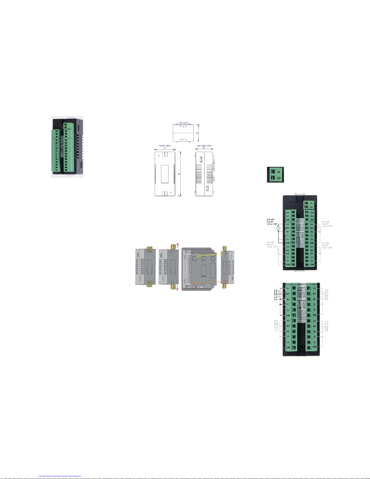
Dimensions: 3.11 x 1.18 x 1.42 inches
[79x30x36mm]
Dimensional Details:
Mounting Module to HMC7000:
The HMC7 I/O module must be mounted onto the back of a
HMC7000 Series unit using one of the HMC expansion ports.
When locating equipment behind the HMC7000 ensure that AC
power wiring, PLC output modules, contactors, starters, relay
and any other source of electrical interference are located
away from the HMC7000. Make sure that variable speed drives
and switching power supplies are located away from the unit.
Step 1 Step 2 Step 3
Step 1: Pull the two white lock connectors out from the center
of the module.
Step 2: Place the module onto the HMC7000 expansion port so
that the I/O module interconnect plug can attach to the
HMC7000 socket. Note: remove the protective tab on the
HMC7000 expansion port to expose the socket.
Step 3: Push down the lock connectors to safely secure the I/O
Expansion module.
Wiring I/O Expansion Modules:
The HMC7 I/O module has green block terminals that are used
to wire the module to the digital input devices (i.e. switches,
contacts, etc). The block terminals can be physically removed
from the module to facilitate connection (18-gauge wire
recommended). Note: A 3/32” flat blade screwdriver should be
used to tighten the screws of the terminal block.
Note: 24VDC must be supplied to the pins as marked or the
module will not be recognized by the HMC or function.
Connection for analog voltage inputs:
Connection for analog current inputs:
Page 2
Model HMC7-MIO-08
Phone: 425/745-3229 • Fax: 425/745-3429 • Email: maple@maplesystems.com • www.maplesystems.com
Doc. No. 1011-0715 Page 2 of 2 Rev. 05, 05/18/2016
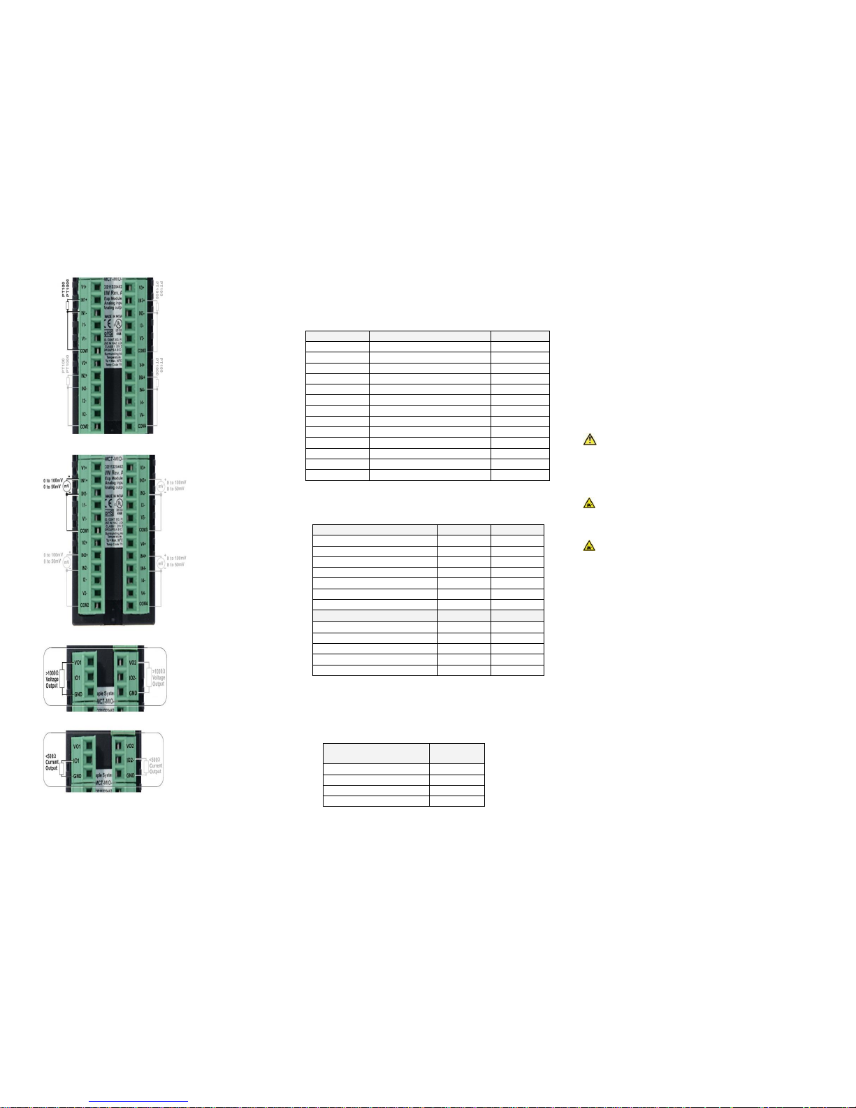
Connection for RTD inputs:
Connection for mV/thermocouple inputs:
Connection for voltage outputs:
Connection for current outputs:
Configuration:
Use MAPware-7000 to assign input (XW) output (YW) and
configuration (MW) memory addresses to the module.
These addresses are created according to the slot location of
the module, where nn refers to the slot number (ex. 01… 05):
Register
Description
Access
XWnn00
Input Channel 1 Data
Read Only
XWnn02
Input Channel 2 Data
Read Only
XWnn04
Input Channel 3 Data
Read Only
XWnn06
Input Channel 4 Data
Read Only
YWnn00
Output Channel 1 Data
Read/Write
YWnn01
Output Channel 2 Data
Read/Write
MWnn00
Input Channel 1 Config. Reg.
Read/Write
MWnn01
Input Channel 2 Config. Reg.
Read/Write
MWnn02
Input Channel 3 Config. Reg.
Read/Write
MWnn03
Input Channel 4 Config. Reg.
Read/Write
MWnn04
Output Channel 1 Config. Reg.
Read/Write
MWnn05
Output Channel 2 Config. Reg.
Read/Write
MWnn10
Analog Input Error Reg.
Read/Write
Reference the table below when configuring each Input
Configuration Register (MWnn00 – MWnn03)
Input Channel Signal Type
Value
Value
Voltage 0 to 10V
1 - Voltage, 0 to 5V
6
-
Voltage, -10 to +10
18
-
Voltage, 0 to 50 mV
5 - Voltage, 0 to 100mV
4 - Current, 4 to 20mA
2
-
Current, 0 to 20mA
3
-
RTD and Thermocouple
For °C
For °F
RTD, PT100, alpha11
7
19
RTD, PT100, alpha21
8
20
RTD, PT1000
9
21
Thermocouple Type J2
14
26
Thermocouple Type K2
15
27
1. alpha1= 0.00385 Ω/Ω/°C, alpha2=0.003926 Ω/Ω/°C
2. 15-minute module warm-up time recommended
Reference the table below when configuring each
Output Configuration Register (MWnn04 – MWnn05)
Output Channel Signal
Type
Value
Voltage, 0 to 10V
2
Voltage, 0 to 5V
1
Current, 4 to 20mA
5
Current, 0 to 20mA
6
Additional Resources:
Detailed instructions on the operation and installation of the
HMC7000 Series are available in the HMC7000 Programming
Manual that is included with the MAPware-7000 configuration
software. MAPware-7000 also includes help files, which
provide detailed information on using the configuration
software.
WARNING: DO NOT REMOVE OR REPLACE WHILE CIRCUIT
IS LIVE UNLESS THE AREA IS KNOWN TO BE FREE OF
IGNITIBLE CONCENTRATIONS OF FLAMMABLE SUBSTANCES.
This equipment is suitable for use in Class I, Division 2, Groups
A, B, C and D or non-hazardous locations only.
WARNING – EXPLOSION HAZARD – Do not disconnect
equipment unless power has been removed or the area is
known to be non-hazardous.
WARNING – EXPLOSION HAZARD - Substitution of
components may impair suitability for Class I, Division 2.
It is recommended that the user periodically inspect the sealed
devices used, check for any degradation of properties, and
replace as necessary.
For Technical Support:
Please contact Maple Systems if you have any questions
regarding this product. We ask that you provide us with the
unit serial number and firmware revision number written on
the product label of the unit.
Maple Systems Inc.
808 134th St. SW, STE 120
Everett, WA 98204
Tel: 425-745-3229
Fax: 425-745-3429
Email: support@maplesystems.com
Website: www.maplesystems.com
 Loading...