

Page 1
Quick Start Guide
HMC7070A-M
Maple Systems Inc. 808 134th Street SW, Suite 120, Everett, WA 98204-7333 • www.maplesystems.com
.Doc. No. 1011-7070AM Page 1 of 2 Rev. 01, 03/13/18
Description:
HMC7070A-M- 800 x480 pixels, 7" Color TFT, with five
expansion slots, an Ethernet port and two serial ports
Contents:
1 HMC7070A-M
1 plastic bag containing four mounting clamps (each
clamp consisting of cap nut, bolt, and clamp)
1 three prong green power plug
Cardboard package inserts
Quick Start Guide
Programming software (MAPware-7000), cables, and power
supply purchased separately.
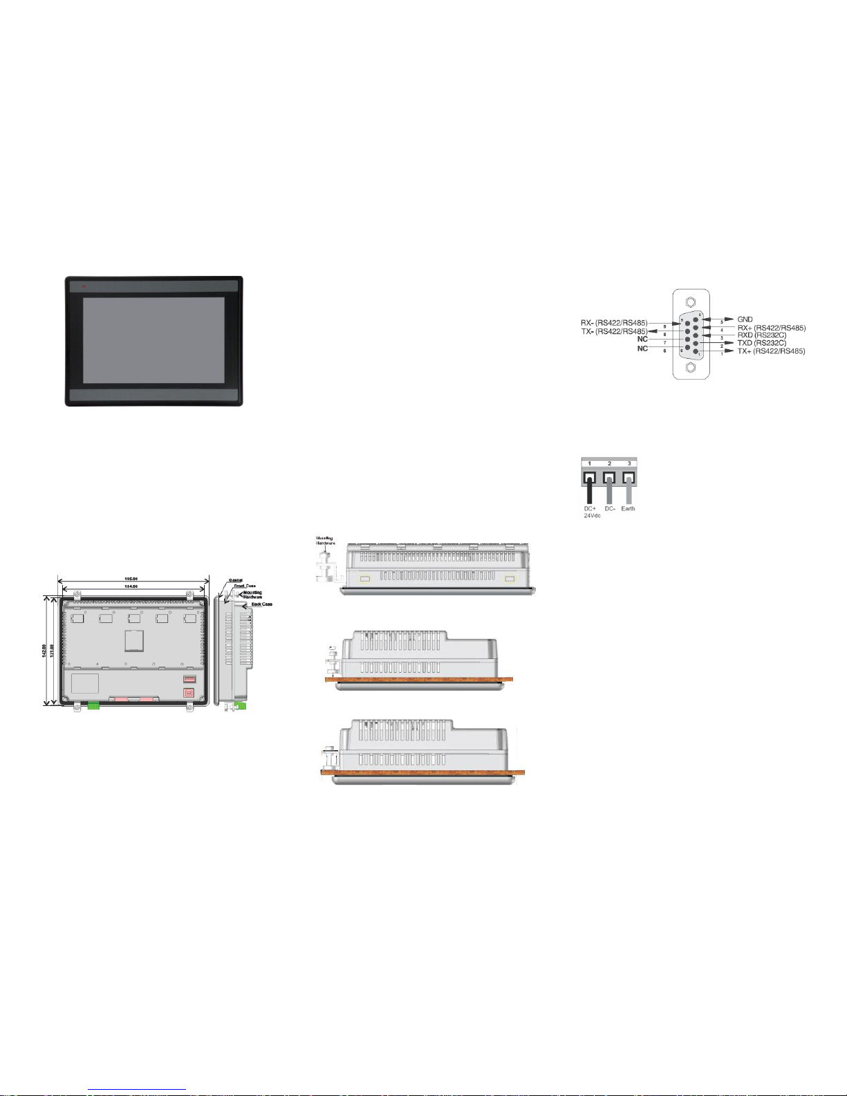
Panel Mounting and Panel Cutout:
HMC7070A-M
Tighten the mounting screws evenly to a torque between 0.6
and 0.7 nm to maintain water and dust resistance. Make sure
the panel is not dirty and warped and that it is strong enough
to hold the unit.
Note: Maximum panel thickness (on which unit is to be
mounted) should be 6.0mm (tolerance: +0.00mm and -
0.05mm).
Specifications:
The HMC7070A-M is a combination operator-based HMI
(Human Machine Interface) with built-in PLC (programmable
logic controller) operation. It communicates with external
PLCs over an Ethernet port, or serial communications port to
read/write data. Up to five I/O expansion modules can be
attached.
Power: 24VDC + 15%, 9W
Display: 7” TFT(800x480 pixels)
Color graphics display
Bezel: NEMA 4 (IP 66) rated
Touchscreen: 4-wire analog resistive
LED: One Power LED
Memory: 10 MB Max. Application Memory
Ethernet: One Ethernet port (Project Upload/
download and PLC communications)
Serial Ports: Two serial ports (RS232/RS485/RS422)
USB Slave: Upload/download projects
USB Host: Data Storage
Operating Temp: 0 to 50° C
Humidity: 10% to 90% (non-condensing)
Dimensions: 7.68 x 5.59 x 1.97 inches
[195x142x50mm]
Panel cutout: 7.24 x 5.16 inches
[184x131mm]
Mounting Unit to Panel:
Step 1: Place unit into cutout of panel and position mounting
clamps (four) into side slots of HMC7000 enclosure as shown
above.
Step 2: Tighten clamps evenly to prevent warping. Continue to
tighten until a torque force of 0.6-0.7 nm is obtained.
Step 3: HMC7000 should be aligned evenly with the cutout
with no warping present after clamps are tightened.
Port Details (COM1 and COM2):
DB9S (Female) Connector
Grounding:
The HMC7000 should have a good electrical connection to
earth ground via the power connector for safety and to reduce
electrical noise. The HMC unit should be grounded separately
from other high-power systems.
Note: Do not use a ground connection that has potential
impedance (such as painted screws) or is subject to vibration.
Expansion I/O Modules:
The HMC7070A-M has five expansion slots that you can use to
connect I/O modules. Consult Maple Systems website for a
complete listing of modules currently available.
Page 2
Model: HMC7070A-M
Phone: 425/745-3229 • Fax: 425/745-3429 • Email: maple@maplesystems.com • www.maplesystems.com
.Doc. No. 1011-7070AM Page 2 of 2 Rev. 01, 03/13/18
Getting Started:
Perform the following steps to configure and use the HMC7000
Series unit:
1. Install MAPWare-7000 software.
2. Create your project.
3. Connect a programming cable (USB preferred).
4. Save your project.
5. Download project to HMC7000 (note: you must
select the Download Firmware option for the initial
download).
6. The HMC7000 unit is ready to use in the system.
PC Requirements for MAPware-7000:
Processor: 1GHz Pentium-based processor or equivalent
Operating System Microsoft Windows XP Professional, 2000,
Vista, Windows 7.
RAM: 1 GB
Hard Disk: 800 MB (including 200MB for the .NET Framework
Redistributable)
Display: 1024x768 high color 16-bit
Mouse/Keyboard: Required
USB / Ethernet port: for project downloads
Installing the Software:
1. Insert MAPware-7000 CD into CD-ROM drive and
follow instructions.
2. If software installation does not automatically start
click \ SETUP.EXE from CD directory.
PLC Connecting Cables:
Contact Maple Systems to order any PLC Communications
Cables or to download a cable pinout diagram.
Additional Resources:
Detailed instructions on the operation and installation of the
HMC7000 Series are available in the HMC7000 Programming
Manual that is included with the MAPware-7000 configuration
software. MAPware-7000 also includes help files which
provide detailed information on using the configuration
software.
Other Sources (visit Maple Systems Support Center):
Controller Information Sheets- Specific information
on connecting a particular manufacturer's PLC to the
HMC7000
Cable Drawings- wiring diagrams to particular PLCs
Technical Notes- Provides additional information
and examples not covered in the operations manual
Software Upgrades- Upgrades to the MAPware-7000
software
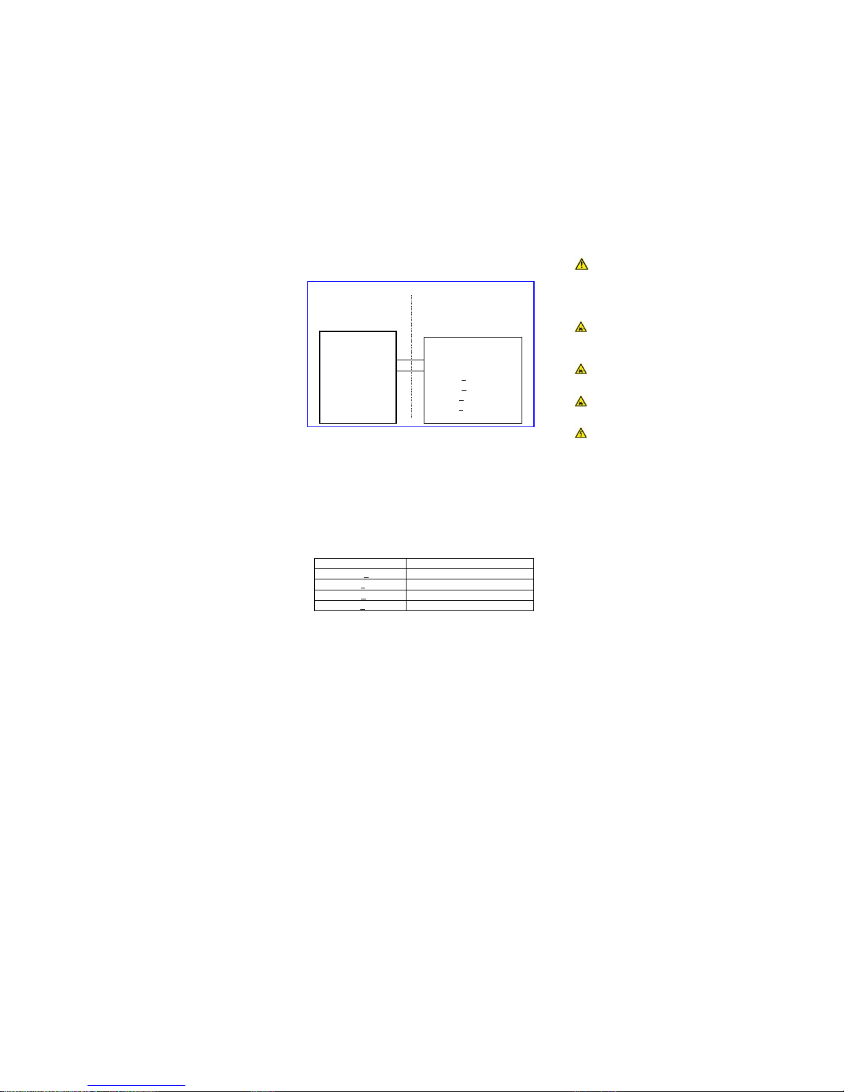
Class I Division 2 Wiring Considerations:
Capacitance and inductance of field wiring from intrinsically
safe equipment to the associated apparatus must be included
in the system calculations as shown in Table 1. Cable
capacitance, C
cable
, plus intrinsically safe equipment
capacitance, Ci, must be less than the marked capacitance, Ca
(or Co), shown on any associated apparatus used. The same
applies for inductance (L
cable
, Li and La or Lo, respectively).
Where the cable capacitance and inductance per foot are not
known, the following values shall be used: C
cable
= 60 pF/ft,
L
cable
= 0.2 μH/ft.
TABLE 1:
I.S. Equipment
Associated Apparatus
V
max
(or Ui) >
Voc or Vt (or Uo)
I
max
(or Ii) >
Isc or It (or Io)
Ci + C
cable
<
Ca (or Co)
Li + L
cable
<
La (or Lo)
Wiring method must be in accordance with ANSI/NFPA70
Associated apparatus may be in a Division 2 or Zone 2 location
if so approved.
Associated apparatus must be installed in accordance with its
manufacturer’s control drawing and National Electrical Code
for installation in the United States and Canadian Electrical
Code for installation in Canada.
WARNING: DO NOT REMOVE OR REPLACE WHILE CIRCUIT
IS LIVE UNLESS THE AREA IS KNOWN TO BE FREE OF
IGNITIBLE CONCENTRATIONS OF FLAMMABLE SUBSTANCES.
This equipment is suitable for use in Class I, Division 2, Groups
A, B, C and D or non-hazardous locations only.
WARNING – EXPLOSION HAZARD – Do not disconnect
equipment unless power has been removed or the area is
known to be non-hazardous.
WARNING – EXPLOSION HAZARD - Substitution of
components may impair suitability for Class I, Division 2.
WARNING - CAUTION, battery may explode if mistreated.
Do not recharge, disassemble or dispose of in fire.
WARNING - Replace battery with Type CR1225FH-LF,
manufactured by Renata SA, only. Use of another battery may
present a risk of fire or explosion. See owner's manual for
safety instructions.
It is recommended that the user periodically inspect the sealed
devices used, check for any degradation of properties, and
replace as necessary.
For Technical Support:
Please contact Maple Systems if you have any questions
regarding this product. We ask that you provide us with the
unit serial number and firmware revision number written on
the product label of the unit. If applicable, please provide us
with the type of PLC used in your application.
Maple Systems Inc.
808 134th St. SW, STE 120
Everett, WA 98204
Tel: 425-745-3229
Fax: 425-745-3429
Email: support@maplesystems.com
Website: www.maplesystems.com
Hazardous Location
Class I Division 2
Groups A, B, C, and D
Non-Hazardous
Location
HMC7070
USB Port
JP9
V
max
=3.3 VDC
I
max
=150 mA
Li=0
Ci=9pF
Associated Apparatus
USB Port
Voc<3.3 VDC
Isc<2.2 mA
La>Li + L
cable
Ca>Ci + C
cable
 Loading...