

Page 1
808 134TH Street SW, Suite 120
Email: maple@maplesystems.com
www.maplesystems.com
HMC7000 Series
Guide
1010-1043 rev02
I/O Module
Everett, WA 98204, USA
Phone: 425-745-3229
Fax: 425-745-3429
Page 2
HMC7000 Series I/O Module Guide
I/O Module Part No.
Description
HMC7-MI-01
16 Digital Inputs (sinking or sourcing)
HMC7-MI-02
4 Programmable Analog Inputs
HMC7-MI-03
8 Programmable Analog Voltage Inputs
HMC7-MI-04
8 Programmable Analog Current Inputs
HMC7-MO-01
12 Relay Outputs
HMC7-MO-02
16 Digital Outputs (Sinking 0.5A)
HMC7-MO-03
16 Digital Outputs (Sourcing 0.5A)
HMC7-MIO-01
8 Bidirectional Digital Inputs, 8 Digital Outputs (Sinking 0.5A)
HMC7-MIO-02
8 Bidirectional Digital Inputs, 8 Digital Outputs (Sourcing 0.5A)
HMC7-MIO-03
2 Programmable Analog Inputs, and 2 Programmable Analog Outputs
HMC7-MIO-04
8 Bidirectional Digital Inputs (4 high speed), 8 Digital Outputs
(Sinking 0.5A)
HMC7-MIO-05
8 Bidirectional Digital Inputs (4 high speed), 8 Digital Outputs
(Sourcing 0.5A)
HMC7-MIO-06
8 Bidirectional Digital Inputs (4 high speed), 8 Digital Outputs
(2 PWM, Sinking 0.5A), 6 Relay
HMC7-MIO-07
8 Bidirectional Digital Inputs (4 high speed), 8 Digital Outputs
(2 PWM, Sourcing 0.5A), 6 Relay
HMC7-MIO-08
4 Programmable Analog Inputs, 2 Programmable Analog Outputs
HMC Part No.
Description
HMC7030A-L
3” LCD, 18 membrane-style keys, 1 serial port, 1 USB slave port,
12 digital inputs and 8 digital outputs built-in
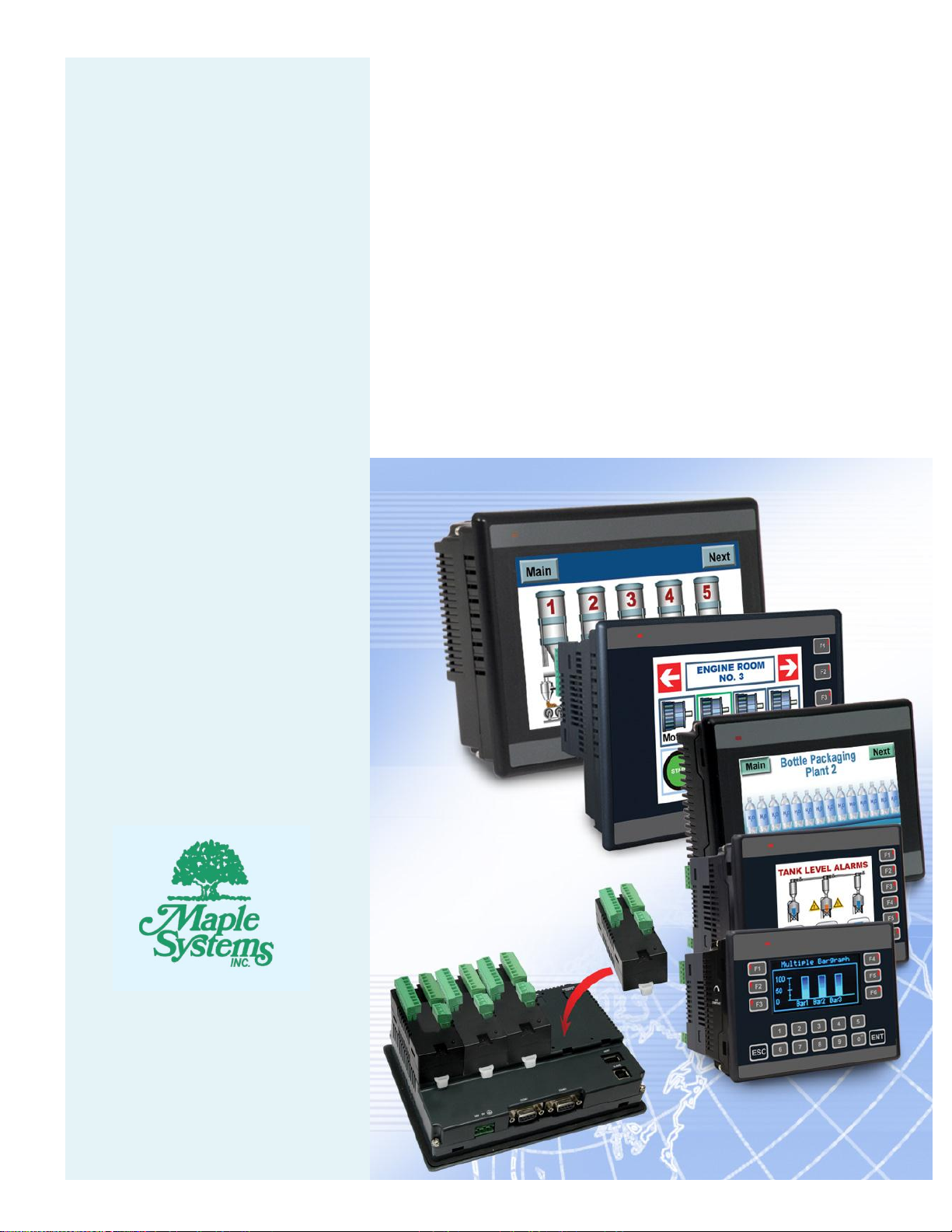
Introduction
The HMC7000 Series (except for the HMC7030A-L) support I/O expansion modules. These
modules provide digital and/or analog I/O (inputs and outputs) for an electrical control system.
All of the I/O Modules are CE and UL Certified. The following I/O Modules are available:
Some HMC7000 Series models have built in I/O. These units are also CE and UL Certified.
Maple Systems Inc., 808 134th Street SW, Suite 120, Everett, WA 98204-7333 • www.maplesystems.com
1010-1043 Page 1 of 35 Rev. 02, 11/08/2013
Page 3
HMC7000 Series I/O Module Guide
Power
3.9 VDC from HMC7000 base
Approvals
CE, UL
Digital Inputs
16 bidirectional inputs (2 high-speed )
Rated input current
Up to 5mA (per contact)
Input impedance
4.9K ohms
Minimum ON voltage
15 VDC
Maximum OFF voltage
5 VDC
Turn ON Time
10 msec
Turn OFF Time
10 msec
Isolation
Optically isolated from internal circuit
Connection method
Removable terminals (3.81 mm pitch)
High Speed Channels
No. of inputs
2 channels (X0 and X5)
Maximum Input Frequency
25 KHz
Maximum Input Count
4,294,967,295 (32-bit)
General
Operating Temperature
0 to 55°C
Operating Humidity
10% to 90% (non condensing)
Mechanical Dimension (LxWxH)
3.11x1.18x1.42 inches [79x30x36mm]
I/O Modules
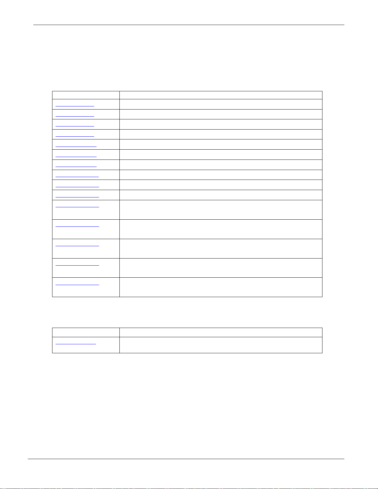
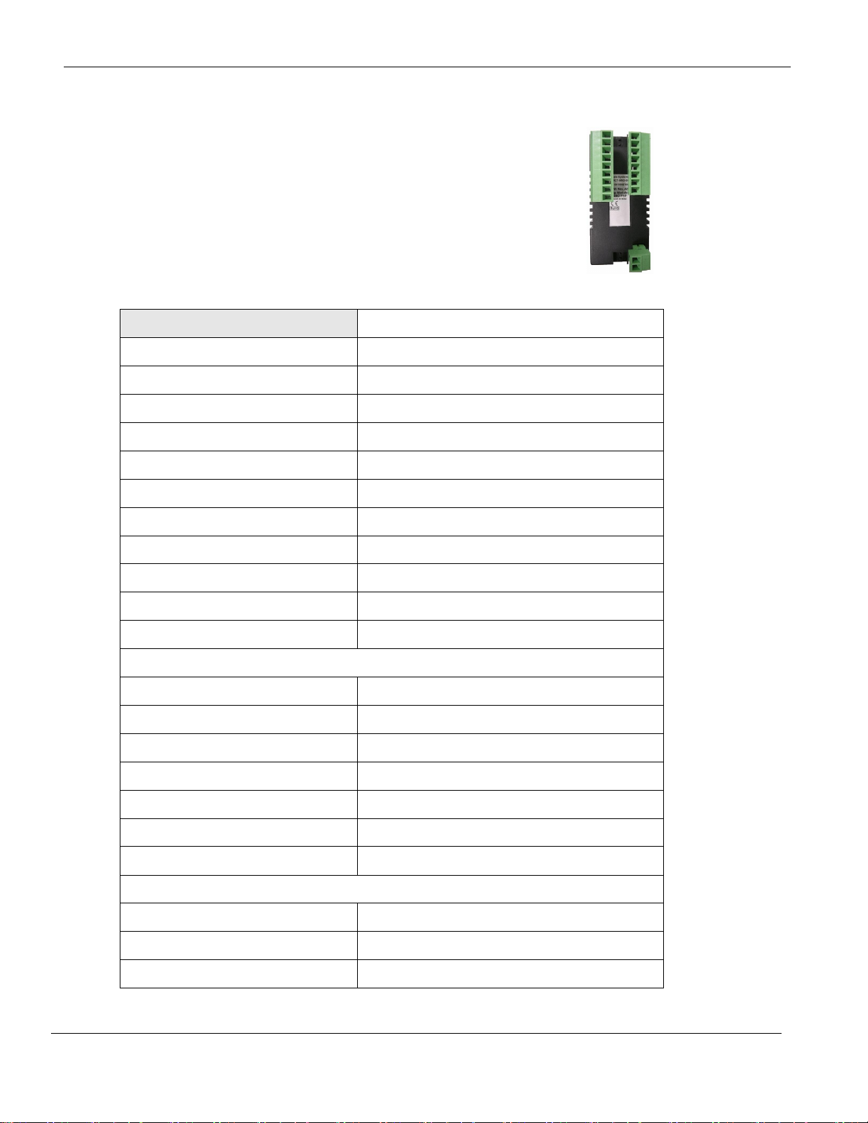
HMC7-MI-01 (16 Digital Input Module)
This module is a digital input module for the HMC7000
Series models. It has sixteen bidirectional inputs, two of
which are high-speed inputs.
Specifications:
Phone: 425/745-3229 • Fax: 425/745-3429 • Email: maple@maplesystems.com • www.maplesystems.com .
1010-1043 Page 2 of 85 Rev. 02, 11/08/2013
Page 4
HMC7000 Series I/O Module Guide
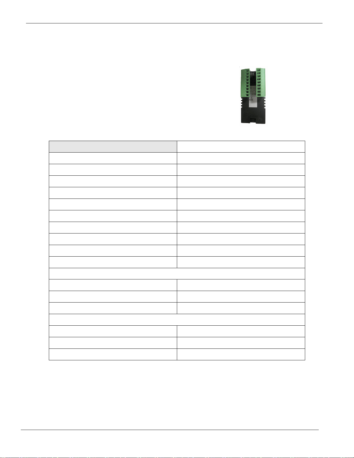
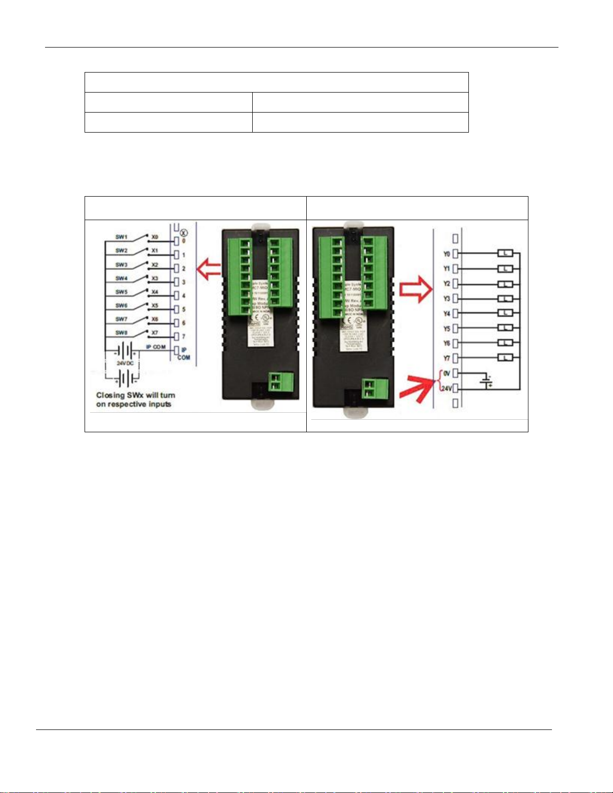
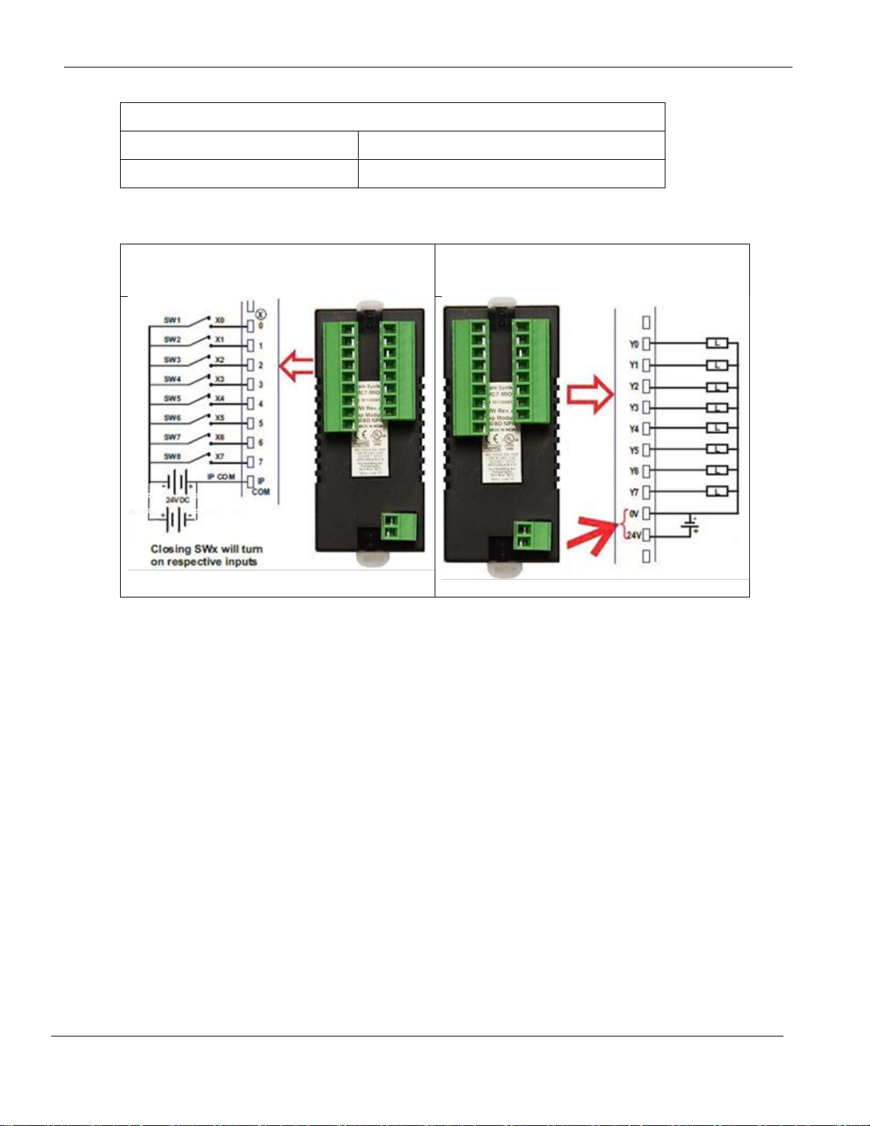
For connecting to NPN-type transistor inputs:
Connecting to PNP-type transistor inputs:
Function
Register
Access
X0-X15 Inputs
Xnn000-015 (XWnn00)
Rd Only
High Speed Counter Option
HSC
Channel 1
HSC
Channel 2
HSC Input Pin
X0
X5
Rd Only
HSC Reset Input Pin
X1
X6
Rd Only
HSC Configuration Register
MWnn00
MWnn06
Rd/Write
HSC Counter Register
(Current Value)
MWnn01
MWnn02
MWnn07
MWnn08
Rd/Write
HSC Preset Register
MWnn03
MWnn04
MWnn09
MWnn10
Rd/Write
HSC Enable Bit
Mnn080
Mnn176
Rd/Write
HSC Reset Bit
Mnn081
Mnn177
Rd/Write
Wiring:
Configuration:
Use MAPware-7000 to assign input (X and XW) and configuration (M and MW) memory addresses to the module.
These addresses are created according to the slot location of the module, where nn refers to the slot
number (ex. 01…05):
Phone: 425/745-3229 • Fax: 425/745-3429 • Email: maple@maplesystems.com • www.maplesystems.com .
1010-1043 Page 3 of 85 Rev. 02, 11/08/2013
Page 5

HMC7000 Series I/O Module Guide
Bits
Function
15-4
Not used
3
0 : Falling Edge
1 : Rising Edge
2, 1, 0
Module Operating Mode :
000 : Normal Operation
010 : Up Counter HSC
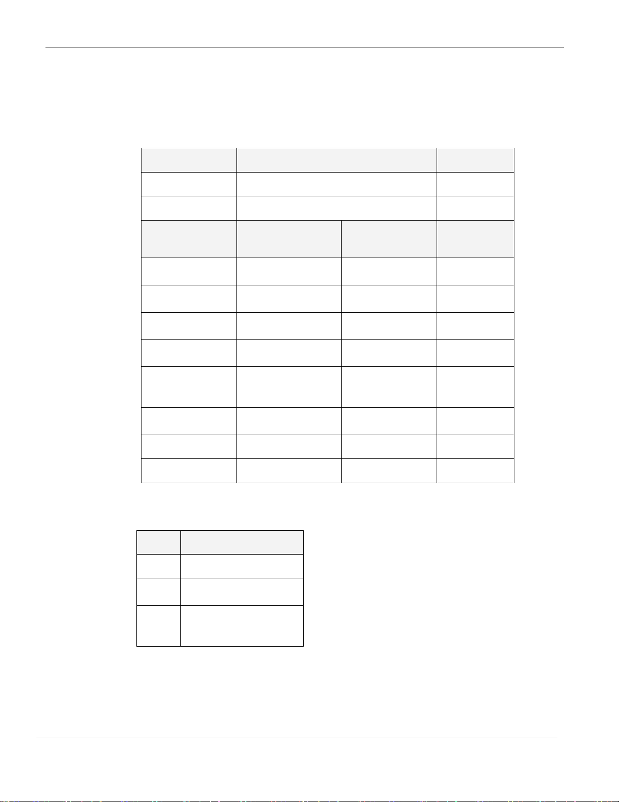
Reference the table below when configuring each HSC Configuration Register (MWnn00 and MWnn06):
To implement High Speed Counter Operation:
1. Connect a device to X0 (Channel 1) or X5 (Channel 2) that will provide the high speed pulses to the
expansion module.
2. Configure the HSC using the configuration register MWnn00 (Channel 1) or MWnn06 (Channel 2).
3. Write the HSC preset count value in MWnn03 (Channel 1) or MWnn09 (Channel 2).
4. Enable the HSC by setting the HSC Enable Bit Mnn080 (Channel 1) or Mnn176 (Channel 2).
5. HSC increments (starting from 0) the current value register in MWnn01 (Channel 1) or MWnn07 (Channel
2) until the preset value is reached.
6. Enable the HSC Reset Bit by setting Mnn081 (Channel 1) or Mnn177 (Channel 2). This will cause the
HSC current value to reset back to 0.
7. To start the process again, simply reset (clear) the HSC Reset Bit and set the HSC Enable Bit. Note: if the
HSC Enable Bit is still ON, you must reset (clear) this bit, and then set it again.
Phone: 425/745-3229 • Fax: 425/745-3429 • Email: maple@maplesystems.com • www.maplesystems.com .
1010-1043 Page 4 of 85 Rev. 02, 11/08/2013
Page 6
HMC7000 Series I/O Module Guide
Power
3.9 VDC from HMC7000 base
Approvals
CE, UL
Analog Inputs
4 Inputs (0-10V, -10 to +10V, 0-20mA, and 4-20mA)
Resolution
12 bit
Connection method
Removable terminals (3.81 mm pitch)
Voltage Mode
Input range
-10V to +10V, 0 - 10V
Value of LSB:
For 0-10V: 2.44mV
For +/-10V: 4.88mV
Input Impedance
200KΩ
Accuracy
At 25°C: 0.1% of full scale
Overall Accuracy (-25°C to 55°C) 0.3% of full scale
Frequency Limit (-3db)
3.5KHz
Behavior upon sensor failure
Input goes to 0, as if no input is connected
Current Mode
Input Range
4mA-20mA, 0mA-20mA
Value of LSB
3.906 μA
Input Impedance
120Ω
Accuracy
At 25°C: 0.2% of full scale
Overall Accuracy (-25°C to 55°C) 0.8% of full scale
General
Operating Temperature
0 to 55°C
Operating Humidity
10% to 90% (non condensing)
Mechanical Dimension (LxWxH)
3.11x1.18x1.42 inches [79x30x36mm]
Input Power Supply
Input Voltage
24VDC
Input Current
50mA
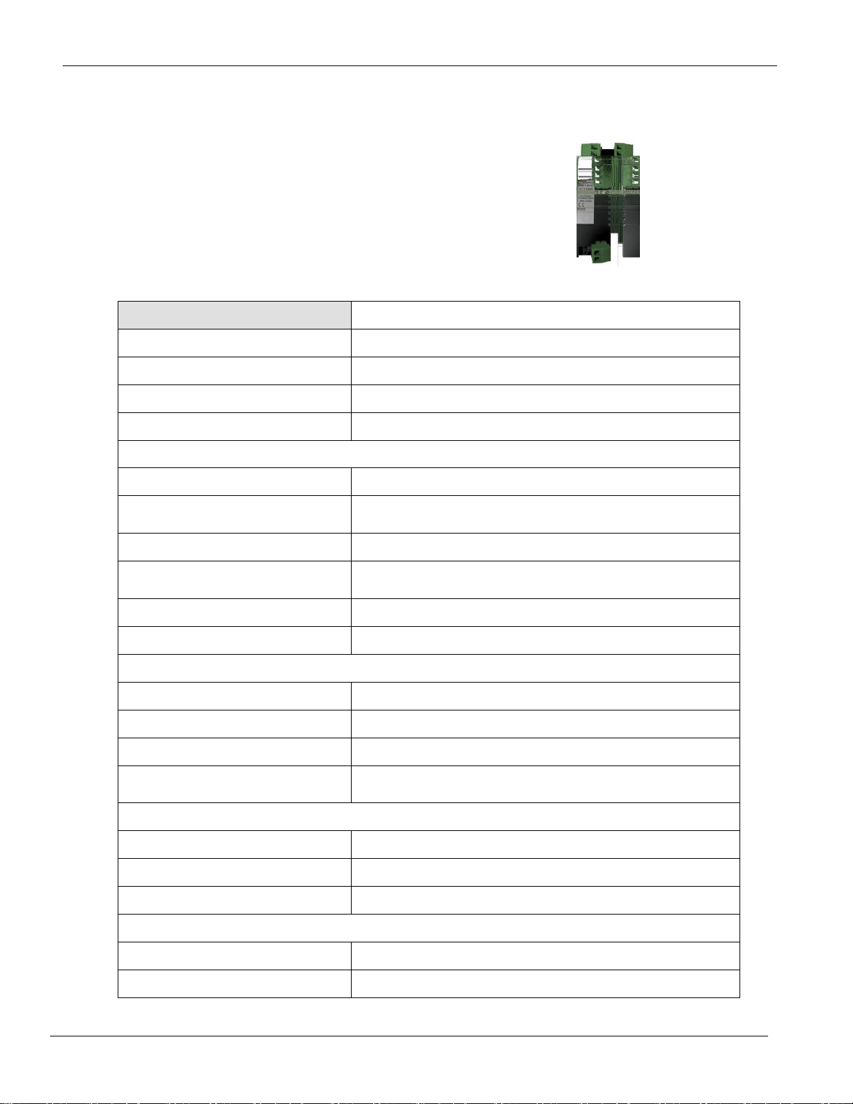
HMC7-MI-02 (4 Input Analog Module)
This module is an analog input module for the HMC7000
Series models. It has four analog inputs, which can measure
0-10V, -10 to +10V, 0-20mA, and 4-20mA signals.
Specifications:
Phone: 425/745-3229 • Fax: 425/745-3429 • Email: maple@maplesystems.com • www.maplesystems.com .
1010-1043 Page 5 of 85 Rev. 02, 11/08/2013
Page 7
HMC7000 Series I/O Module Guide
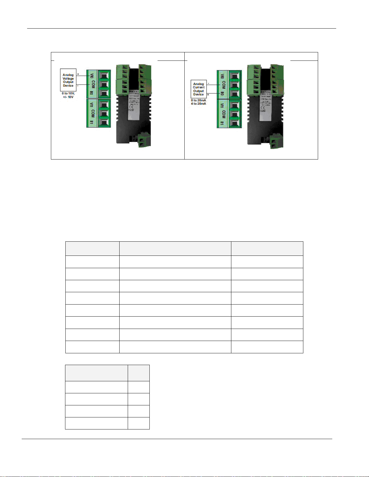
For connecting to analog voltage inputs:
Connecting to analog current inputs:
Register
Description
Access
XWnn00
Input Channel 1 Data
Read Only
XWnn01
Input Channel 2 Data
Read Only
XWnn02
Input Channel 3 Data
Read Only
XWnn03
Input Channel 4 Data
Read Only
MWnn00
Input Channel 1 Configuration Register
Read/Write
MWnn01
Input Channel 2 Configuration Register
Read/Write
MWnn02
Input Channel 3 Configuration Register
Read/Write
MWnn03
Input Channel 4 Configuration Register
Read/Write
Input Channel
Signal Type
Value
mA (4-20mA)
0
Voltage (0-10V)
1
Voltage (-10 to +10V)
2
mA (0-20mA)
3
Wiring:
Configuration:
Use MAPware-7000 to assign input (XW) and configuration (MW) memory addresses to the module.
These addresses are created according to the slot location of the module, where nn refers to the slot
number (ex. 01…05):
Reference the table below when configuring each Input Configuration Register (MWnn00-MWnn03):
Phone: 425/745-3229 • Fax: 425/745-3429 • Email: maple@maplesystems.com • www.maplesystems.com .
1010-1043 Page 6 of 85 Rev. 02, 11/08/2013
Page 8
HMC7000 Series I/O Module Guide
Power
3.9 VDC from HMC7000 base
Approvals
CE, UL
Analog Inputs
8 Inputs (0-10V, -10 to +10V)
Resolution
12 bit
Connection method
Removable terminals (3.81 mm pitch)
Voltage Mode
Input range
-10V to +10V, 0 - 10V
Value of LSB:
For 0-10V: 2.44mV
For +/-10V: 4.88mV
Input Impedance
200KΩ
Accuracy
At 25°C: 0.1% of full scale
Overall Accuracy (-25°C to 55°C) 1% of full scale
Frequency Limit (-3db)
3.5KHz
Behavior upon sensor failure
Input goes to 0, as if no input is connected
General
Operating Temperature
0 to 55°C
Operating Humidity
10% to 90% (non condensing)
Mechanical Dimension (LxWxH)
3.11x1.18x1.42 inches [79x30x36mm]
Input Power Supply
Input Voltage
24VDC
Input Current
50mA
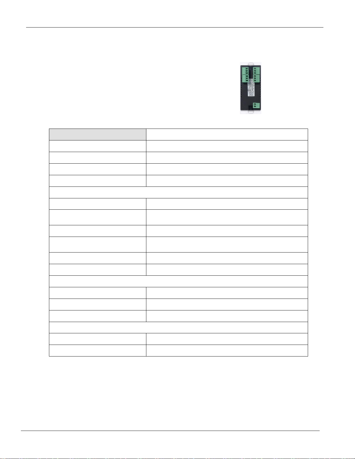
HMC7-MI-03 (8 Voltage Input Analog Module)
This module is an analog input module for the HMC7000
Series models. It has eight analog inputs, which can measure
0-10V, and -10 to +10Vsignals.
Specifications:
Phone: 425/745-3229 • Fax: 425/745-3429 • Email: maple@maplesystems.com • www.maplesystems.com .
1010-1043 Page 7 of 85 Rev. 02, 11/08/2013
Page 9
HMC7000 Series I/O Module Guide
Register
Description
Access
XWnn00
Input Channel 1 Data
Read Only
XWnn01
Input Channel 2 Data
Read Only
XWnn02
Input Channel 3 Data
Read Only
XWnn03
Input Channel 4 Data
Read Only
XWnn04
Input Channel 5 Data
Read Only
XWnn05
Input Channel 6 Data
Read Only
XWnn06
Input Channel 7 Data
Read Only
XWnn07
Input Channel 8 Data
Read Only
MWnn00
Input Channel 1 Configuration Register
Read/Write
MWnn01
Input Channel 2 Configuration Register
Read/Write
MWnn02
Input Channel 3 Configuration Register
Read/Write
MWnn03
Input Channel 4 Configuration Register
Read/Write
MWnn04
Input Channel 5 Configuration Register
Read/Write
MWnn05
Input Channel 6 Configuration Register
Read/Write
MWnn06
Input Channel 7 Configuration Register
Read/Write
MWnn07
Input Channel 8 Configuration Register
Read/Write
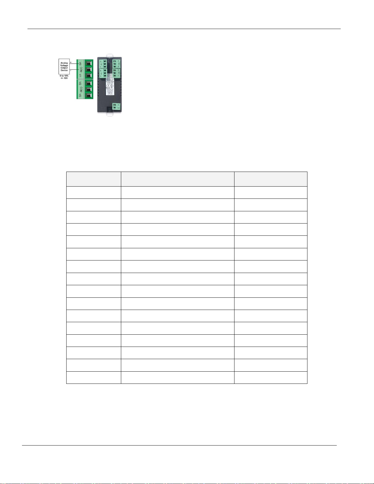
Wiring:
Configuration:
Use MAPware-7000 to assign input (XW) and configuration (MW) memory addresses to the module.
These addresses are created according to the slot location of the module, where nn refers to the slot
number (ex. 01…05):
Phone: 425/745-3229 • Fax: 425/745-3429 • Email: maple@maplesystems.com • www.maplesystems.com .
1010-1043 Page 8 of 85 Rev. 02, 11/08/2013
Page 10

HMC7000 Series I/O Module Guide
Input Channel
Signal Type
Value
Voltage (0 - 10V)
1
Voltage (-10 to +10V)
2
Reference the table below when configuring each Input Configuration Register (MWnn00-MWnn07):
Phone: 425/745-3229 • Fax: 425/745-3429 • Email: maple@maplesystems.com • www.maplesystems.com .
1010-1043 Page 9 of 85 Rev. 02, 11/08/2013
Page 11
HMC7000 Series I/O Module Guide
Power
3.9 VDC from HMC7000 base
Approvals
CE, UL
Analog Inputs
8 Inputs (0-20mA, 4-20mA)
Resolution
12 bit
Connection method
Removable terminals (3.81 mm pitch)
Voltage Mode
Input range
0-20mA, 4-20mA
Value of LSB:
3.906uA
Input Impedance
120Ω
Accuracy
At 25°C: 0.1% of full scale
Overall Accuracy (-25°C to 55°C) 1% of full scale
General
Operating Temperature
0 to 55°C
Operating Humidity
10% to 90% (non condensing)
Mechanical Dimension (LxWxH)
3.11x1.18x1.42 inches [79x30x36mm]
Input Power Supply
Input Voltage
24VDC
Input Current
50mA
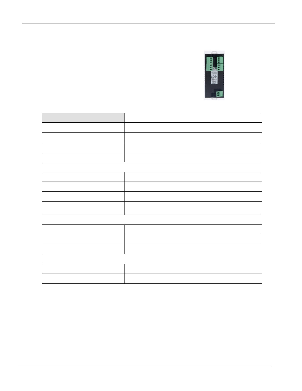
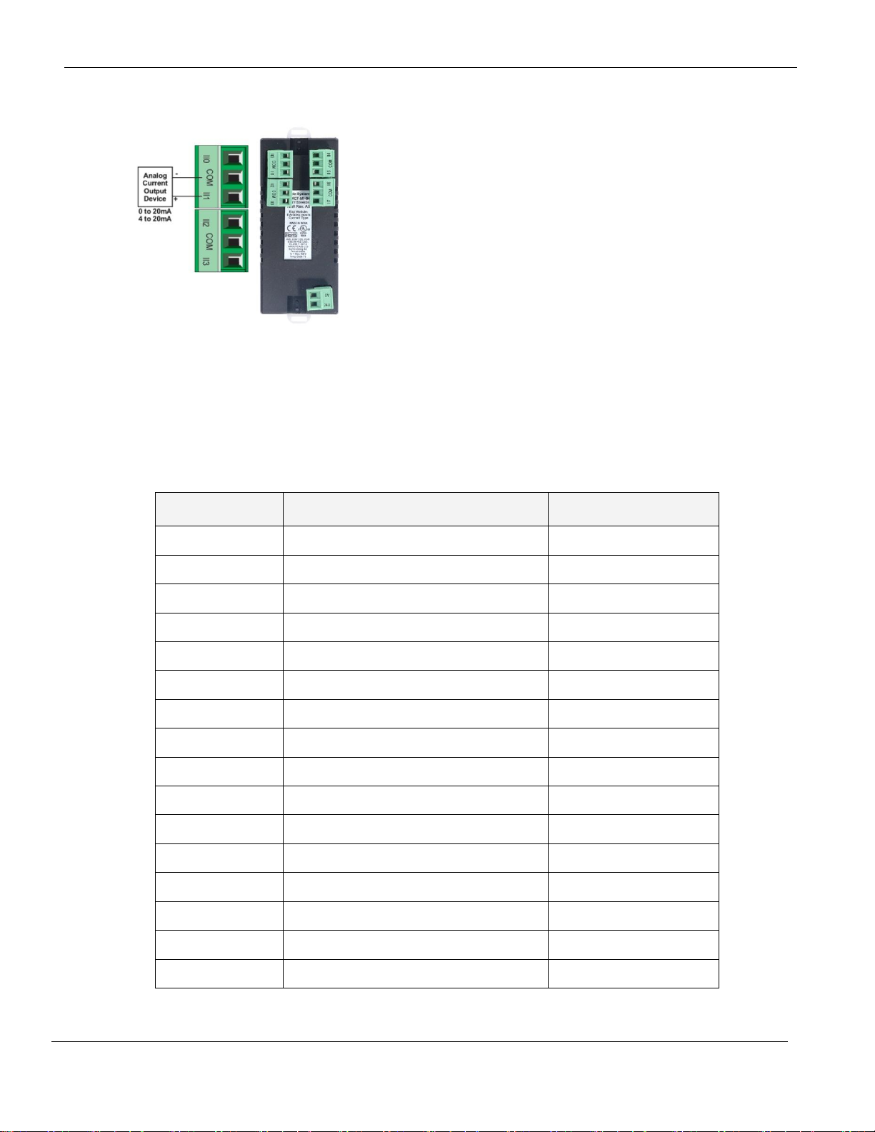
HMC7-MI-04 (8 Current Input Analog Module)
This module is an analog input module for the HMC7000
Series models. It has eight analog inputs, which can measure
0-20mA, and 4-20mA signals.
Specifications:
Phone: 425/745-3229 • Fax: 425/745-3429 • Email: maple@maplesystems.com • www.maplesystems.com .
1010-1043 Page 10 of 85 Rev. 02, 11/08/2013
Page 12
HMC7000 Series I/O Module Guide
Register
Description
Access
XWnn00
Input Channel 1 Data
Read Only
XWnn01
Input Channel 2 Data
Read Only
XWnn02
Input Channel 3 Data
Read Only
XWnn03
Input Channel 4 Data
Read Only
XWnn04
Input Channel 5 Data
Read Only
XWnn05
Input Channel 6 Data
Read Only
XWnn06
Input Channel 7 Data
Read Only
XWnn07
Input Channel 8 Data
Read Only
MWnn00
Input Channel 1 Configuration Register
Read/Write
MWnn01
Input Channel 2 Configuration Register
Read/Write
MWnn02
Input Channel 3 Configuration Register
Read/Write
MWnn03
Input Channel 4 Configuration Register
Read/Write
MWnn04
Input Channel 5 Configuration Register
Read/Write
MWnn05
Input Channel 6 Configuration Register
Read/Write
MWnn06
Input Channel 7 Configuration Register
Read/Write
MWnn07
Input Channel 8 Configuration Register
Read/Write
Wiring:
Configuration:
Use MAPware-7000 to assign input (XW) and configuration (MW) memory addresses to the module.
These addresses are created according to the slot location of the module, where nn refers to the slot
number (ex. 01…05):
Phone: 425/745-3229 • Fax: 425/745-3429 • Email: maple@maplesystems.com • www.maplesystems.com .
1010-1043 Page 11 of 85 Rev. 02, 11/08/2013
Page 13

HMC7000 Series I/O Module Guide
Input Channel
Signal Type
Value
Current (0 - 20mA)
3
Current (4 – 20mA)
0
Reference the table below when configuring each Input Configuration Register (MWnn00-MWnn07):
Phone: 425/745-3229 • Fax: 425/745-3429 • Email: maple@maplesystems.com • www.maplesystems.com .
1010-1043 Page 12 of 85 Rev. 02, 11/08/2013
Page 14
HMC7000 Series I/O Module Guide
Power
3.9 VDC from HMC7000 base
Approvals
CE, UL
Digital Outputs
12 relay outputs
Turn ON Time
10 msec
Turn OFF Time
5 msec
Output capacity
2A per contact up to 230VAC
2A per contact up to 30VDC
Connection method
Removable terminals (3.81 mm pitch)
General
Operating Temperature
0 to 55°C
Operating Humidity
10% to 90% (non condensing)
Mechanical Dimension (LxWxH)
3.11x1.18x1.42 inches [79x30x36mm]
Input Power Supply
Input Voltage
24VDC (required even when using AC loads)
Input Current
150mA maximum
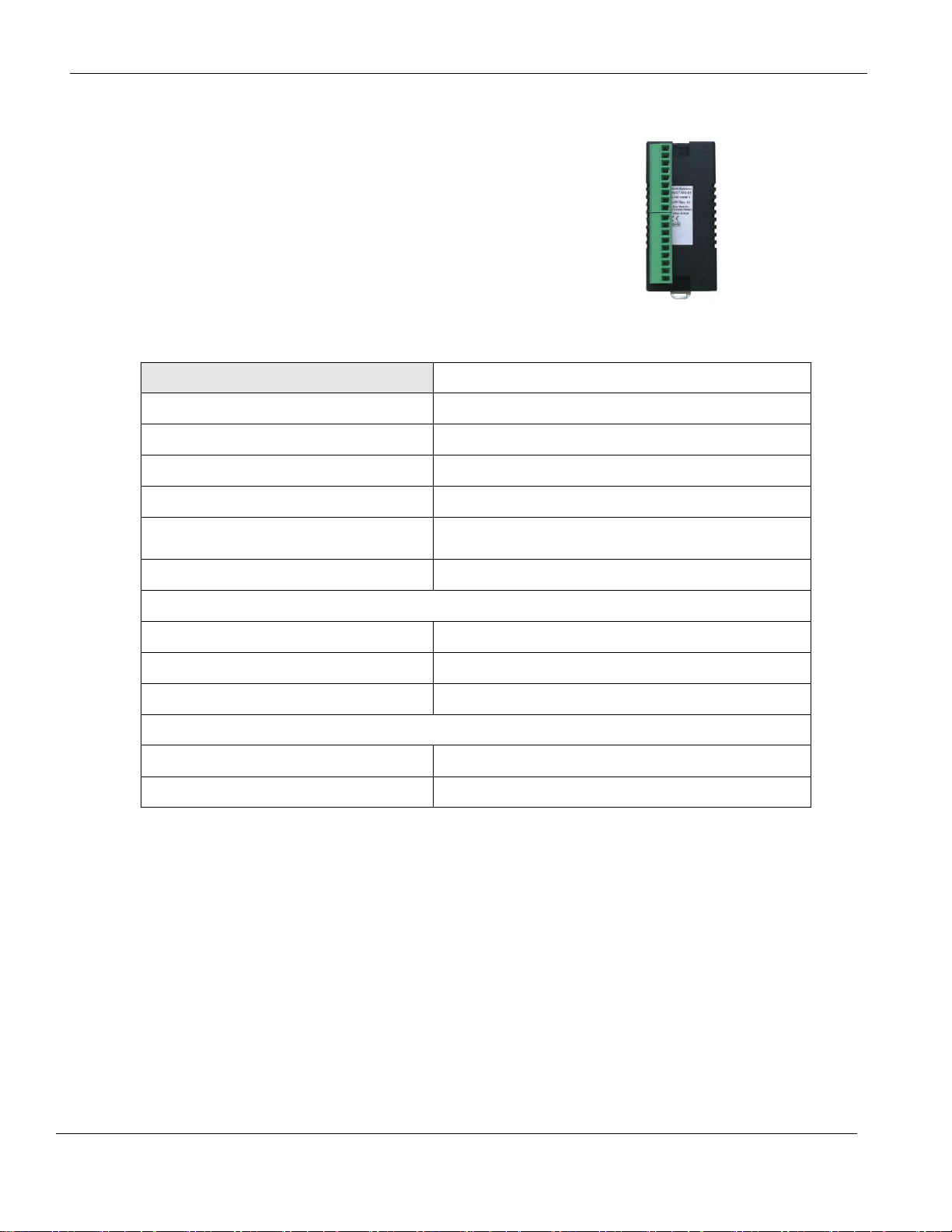
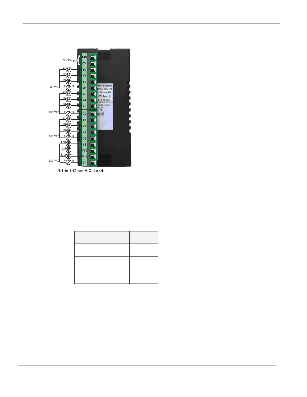
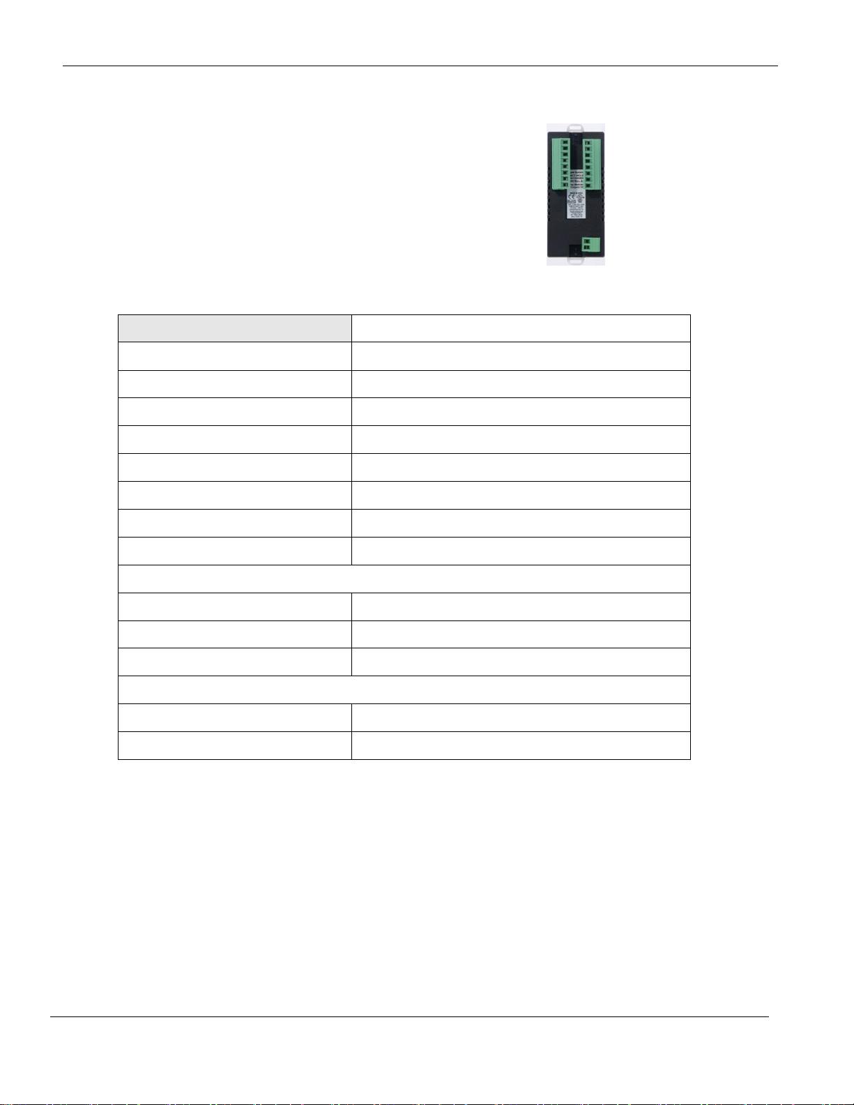
HMC7-MO-01 (12 Relay Output Module)
This module is a digital output module for the HMC7000
Series models. It has twelve relay outputs.
Specifications:
Phone: 425/745-3229 • Fax: 425/745-3429 • Email: maple@maplesystems.com • www.maplesystems.com .
1010-1043 Page 13 of 85 Rev. 02, 11/08/2013
Page 15
HMC7000 Series I/O Module Guide
Register
Description
Access
Ynn000Ynn011
Output Bits
Read/Write
YWnn00
Output
Word Data
Read/Write
MWnn00
Relay
Output
Read/Write
Wiring:
Configuration:
Use MAPware-7000 to assign output (Y and YW), and configuration
(MW) memory addresses to the module. These addresses are created
according to the slot location of the module, where nn refers to the
slot number (ex. 01…05):
Phone: 425/745-3229 • Fax: 425/745-3429 • Email: maple@maplesystems.com • www.maplesystems.com .
1010-1043 Page 14 of 85 Rev. 02, 11/08/2013
Page 16
HMC7000 Series I/O Module Guide
Power
3.9 VDC from HMC7000 base
Approvals
CE, UL
Digital Outputs
16 sinking (NPN) outputs
Turn ON Time
10 msec
Turn OFF Time
10 msec
Output Capacity
500mA per output maximum
Rated load
500mA @ 24VDC
Total output capacity
4A @ 24VDC
Connection method
Removable terminals (3.81 mm pitch)
General
Operating Temperature
0 to 55°C
Operating Humidity
10% to 90% (non condensing)
Mechanical Dimension (LxWxH)
3.11x1.18x1.42 inches [79x30x36mm]
Input Power Supply
Input Voltage
24VDC
Input Current
850mA maximum
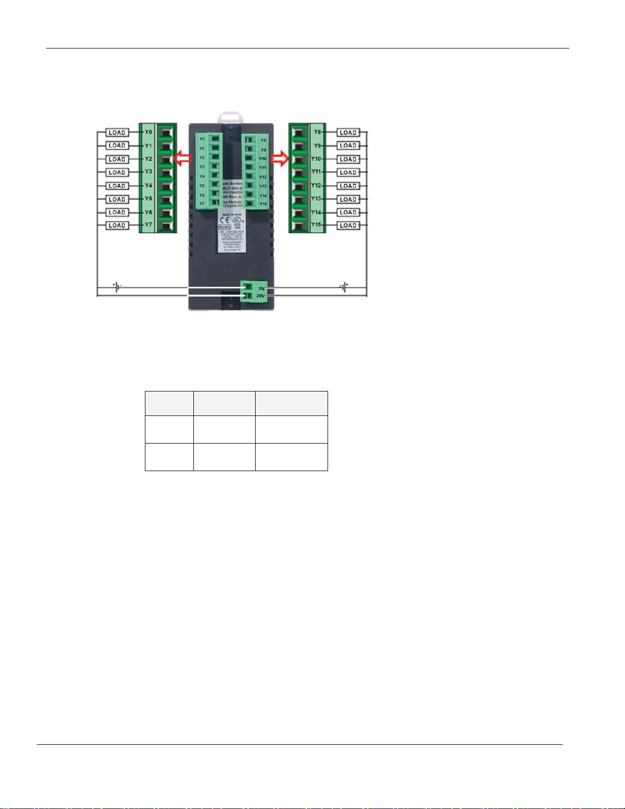
HMC7-MO-02 (16 Sinking Output Module)
This module is a digital output module for the HMC7000 Series
models. It has 16 sinking (NPN) outputs.
Specifications:
Phone: 425/745-3229 • Fax: 425/745-3429 • Email: maple@maplesystems.com • www.maplesystems.com .
1010-1043 Page 15 of 85 Rev. 02, 11/08/2013
Page 17
HMC7000 Series I/O Module Guide
Register
Description
Access
Ynn000Ynn015
Output Bits
Read/Write
YWnn00
Output
Word Data
Read/Write
Wiring:
Configuration:
Use MAPware-7000 to assign output (Y and YW) addresses to the
module. These addresses are created according to the slot location of
the module, where nn refers to the slot number (ex. 01…05):
Phone: 425/745-3229 • Fax: 425/745-3429 • Email: maple@maplesystems.com • www.maplesystems.com .
1010-1043 Page 16 of 85 Rev. 02, 11/08/2013
Page 18
HMC7000 Series I/O Module Guide
Power
3.9 VDC from HMC7000 base
Approvals
CE, UL
Digital Outputs
16 sourcing (PNP) outputs
Turn ON Time
10 msec
Turn OFF Time
10 msec
Output Capacity
500mA per output maximum
Rated load
500mA @ 24VDC
Total output capacity
4A @ 24VDC
Connection method
Removable terminals (3.81 mm pitch)
General
Operating Temperature
0 to 55°C
Operating Humidity
10% to 90% (non condensing)
Mechanical Dimension (LxWxH)
3.11x1.18x1.42 inches [79x30x36mm]
Input Power Supply
Input Voltage
24VDC
Input Current
850mA maximum
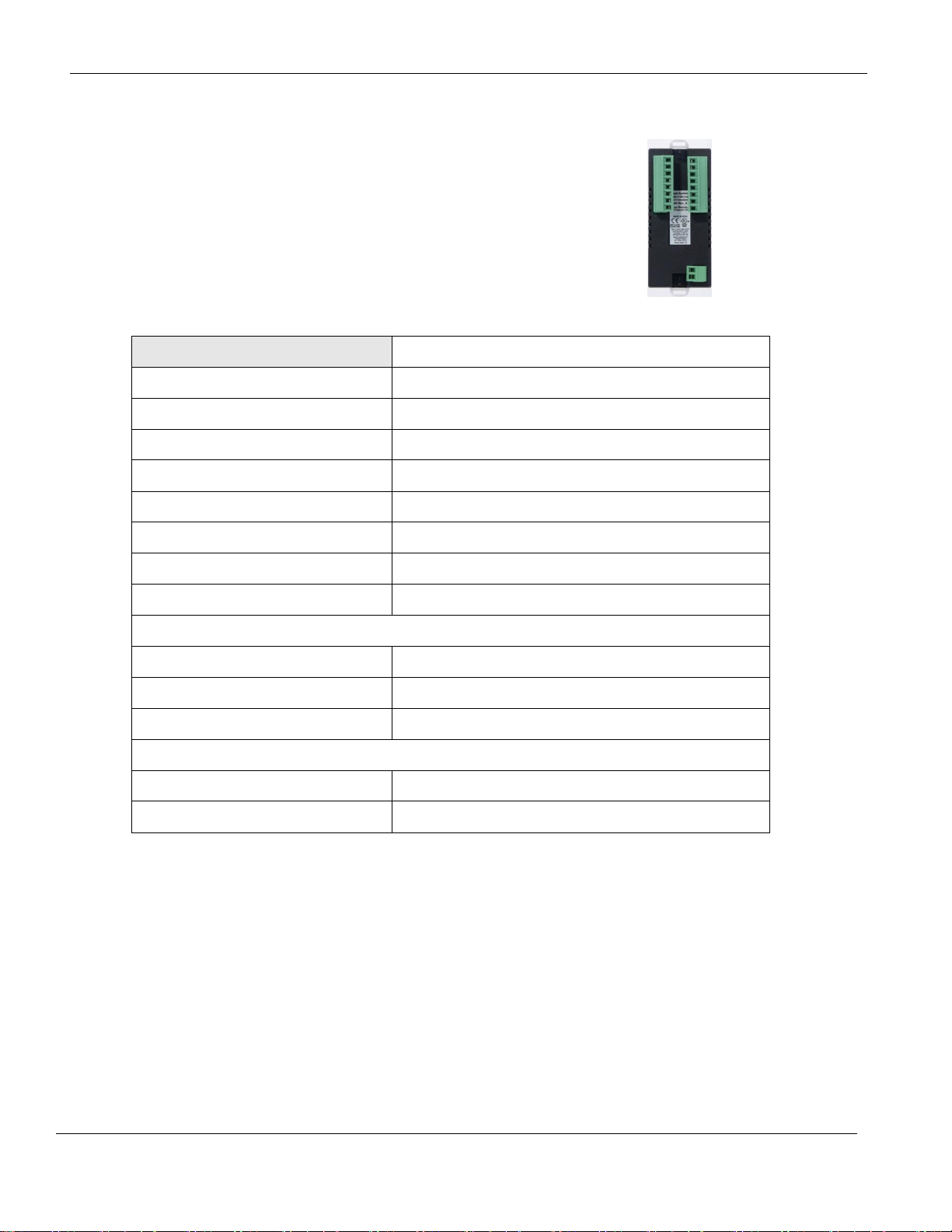
HMC7-MO-03 (16 Sourcing Output Module)
This module is a digital output module for the HMC7000
Series models. It has 16 sourcing (PNP) outputs.
Specifications:
Phone: 425/745-3229 • Fax: 425/745-3429 • Email: maple@maplesystems.com • www.maplesystems.com .
1010-1043 Page 17 of 85 Rev. 02, 11/08/2013
Page 19
HMC7000 Series I/O Module Guide
Register
Description
Access
Ynn000Ynn015
Output Bits
Read/Write
YWnn00
Output
Word Data
Read/Write
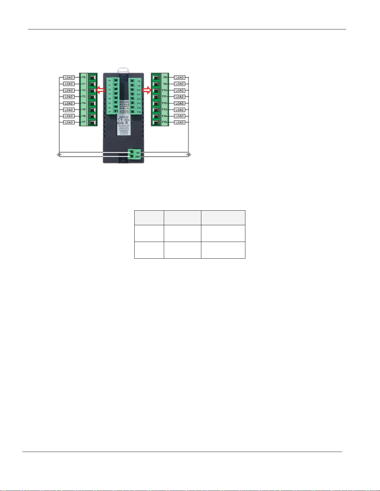
Wiring:
Configuration:
Use MAPware-7000 to assign output (Y and YW) addresses to the module. These addresses are created
according to the slot location of the module, where nn refers to the slot number (ex. 01…05):
Phone: 425/745-3229 • Fax: 425/745-3429 • Email: maple@maplesystems.com • www.maplesystems.com .
1010-1043 Page 18 of 85 Rev. 02, 11/08/2013
Page 20

HMC7000 Series I/O Module Guide
Power
3.9 VDC from HMC7000 base
Approvals
CE, UL
Digital Inputs
8 bidirectional inputs
Rated input voltage
24 VDC
Rated input current
Up to 5mA
Input impedance
4.9K ohms
Minimum ON voltage
15 VDC
Maximum OFF voltage
5 VDC
Turn ON Time
10 msec
Turn OFF Time
10 msec
Isolation
Optically isolated from internal circuit
Connection method
Removable terminals (3.81 mm pitch)
High Speed Channels
No. of inputs
2 channels (X0 and X5)
Maximum Input Frequency
25 KHz
Maximum Input Count
4,294,967,295 (32-bit)
Digital Outputs
8 sinking outputs (NPN-type)
Output Capacity
500mA per output maximum
Rated load
500mA @ 24VDC
Total output capacity
4A @ 24VDC
General
Operating Temperature
0 to 55°C
Operating Humidity
10% to 90% (non condensing)
Mechanical Dimension (LxWxH)
3.11x1.18x1.42 inches [79x30x36mm]
HMC7-MIO-01 (8 Bidirectional Input, 8 Sinking Output Digital Module)
This module is a digital input/output module for the HMC7000
Series models. It has eight bidirectional inputs and eight
sinking digital outputs. Two of the inputs can be configured as
high speed counters (HSC) using the MW registers (see below).
When used as HSCs, input X0 (channel 1) and X5 (channel 2)
are used to record the incoming pulses.
Specifications:
Phone: 425/745-3229 • Fax: 425/745-3429 • Email: maple@maplesystems.com • www.maplesystems.com .
1010-1043 Page 19 of 85 Rev. 02, 11/08/2013
Page 21
HMC7000 Series I/O Module Guide
Input Power Supply
Input Voltage
24VDC
Input Current
4A maximum
For connecting to bidirectional inputs:
Connecting to NPN-type transistor outputs:
Wiring:
Phone: 425/745-3229 • Fax: 425/745-3429 • Email: maple@maplesystems.com • www.maplesystems.com .
1010-1043 Page 20 of 85 Rev. 02, 11/08/2013
Page 22
HMC7000 Series I/O Module Guide
Function
Register
Access
X0-X7 Inputs
Xnn000-007 (XWnn00)
Rd Only
Y0-Y7 Outputs
Ynn000-007 (YWnn00)
Rd/Write
High Speed
Counter Option
HSC Channel 1
HSC Channel 2
HSC Input
X0 (terminal)
Xnn000 (reg)
X5 (terminal)
Xnn005 (reg)
Rd Only
HSC Reset Input
X1 (terminal)
Xnn001 (reg)
X6 (terminal)
Xnn006 (reg)
Rd Only
HSC Output Flag
Y1 (terminal)
Ynn001 (reg)
Y6 (terminal)
Ynn006 (reg)
Rd/Write
HSC Configuration
Register
MWnn00
MWnn06
Rd/Write
HSC Counter
Register
(Current Value)
MWnn01
MWnn02
MWnn07
MWnn08
Rd/Write
HSC Preset Register
MWnn03
MWnn04
MWnn09
MWnn10
Rd/Write
HSC Enable Bit
Mnn080
Mnn176
Rd/Write
HSC Reset Bit
Mnn081
Mnn177
Rd/Write
Bits
Function
15-4
Not used
3
0 : Falling Edge
1 : Rising Edge
2, 1, 0
Module Operating Mode :
000 : Normal Operation
010 : Up Counter HSC
Configuration:
Use MAPware-7000 to assign input (X and XW), output (Y and YW), and configuration (M and MW)
memory addresses to the module. These addresses are created according to the slot location of the module,
where nn refers to the slot number (ex. 01…05):
Reference the table below when configuring each HSC Configuration Register (MWnn00 and MWnn06):
Phone: 425/745-3229 • Fax: 425/745-3429 • Email: maple@maplesystems.com • www.maplesystems.com .
1010-1043 Page 21 of 85 Rev. 02, 11/08/2013
Page 23

HMC7000 Series I/O Module Guide
To implement High Speed Counter Operation:
1. Connect a device to X0 (Channel 1) or X5 (Channel 2) that will provide the high speed pulses to
the expansion module.
2. Configure the HSC using the configuration register MWnn00 (Channel 1) or MWnn06 (Channel
2).
3. Write the HSC preset count value in MWnn03 (Channel 1) or MWnn09 (Channel 2).
4. Enable the HSC by setting the HSC Enable Bit Mnn080 (Channel 1) or Mnn176 (Channel 2).
5. HSC increments (starting from 0) the current value register in MWnn01 (Channel 1) or MWnn07
(Channel 2) until the preset value is reached.
6. Enable the HSC Reset Bit by setting Mnn081 (Channel 1) or Mnn177 (Channel 2). This will
cause the HSC current value to reset back to 0.
7. To start the process again, simply reset (clear) the HSC Reset Bit and set the HSC Enable Bit.
Note: if the HSC Enable Bit is still ON, you must reset (clear) this bit, and then set it again.
Phone: 425/745-3229 • Fax: 425/745-3429 • Email: maple@maplesystems.com • www.maplesystems.com .
1010-1043 Page 22 of 85 Rev. 02, 11/08/2013
Page 24
HMC7000 Series I/O Module Guide
Power
3.9 VDC from HMC7000 base
Approvals
CE, UL
Digital Inputs
8 bidirectional inputs
Rated input voltage
24 VDC
Rated input current
Up to 5mA
Input impedance
4.9K ohms
Minimum ON voltage
15 VDC
Maximum OFF voltage
5 VDC
Turn ON Time
10 msec
Turn OFF Time
10 msec
Isolation
Optically isolated from internal circuit
Connection method
Removable terminals (3.81 mm pitch)
High Speed Channels
No. of inputs
2 channels (X0 and X5)
Maximum Input Frequency
25 KHz
Maximum Input Count
4,294,967,295 (32-bit)
Digital Outputs
8 sourcing outputs (PNP-type)
Output Capacity
500mA per output maximum
Rated load
500mA @ 24VDC
Total output capacity
4A @ 24VDC
General
Operating Temperature
0 to 55°C
Operating Humidity
10% to 90% (non condensing)
Mechanical Dimension (LxWxH)
3.11x1.18x1.42 inches [79x30x36mm]
HMC7-MIO-02 (8 Bidirectional Input, 8 Sourcing Output Digital Module)
This module is a digital input/output module for the HMC7000
Series models. It has eight bidirectional inputs and eight
sourcing digital outputs. Two inputs can be configured as high
speed counters (HSC) using the MW registers (see below).
When used as HSCs, input X0 (channel 1) and X5 (channel 2)
are used to record the incoming pulses.
Specifications:
Phone: 425/745-3229 • Fax: 425/745-3429 • Email: maple@maplesystems.com • www.maplesystems.com .
1010-1043 Page 23 of 85 Rev. 02, 11/08/2013
Page 25
HMC7000 Series I/O Module Guide
Input Power Supply
Input Voltage
24VDC
Input Current
4A maximum
For connecting to bidirectional inputs:
Connecting to PNP-type sourcing outputs:
Wiring:
Phone: 425/745-3229 • Fax: 425/745-3429 • Email: maple@maplesystems.com • www.maplesystems.com .
1010-1043 Page 24 of 85 Rev. 02, 11/08/2013
Page 26

HMC7000 Series I/O Module Guide
Function
Register
Access
X0-X7 Inputs
Xnn000-007 (XWnn00)
Rd Only
Y0-Y7 Outputs
Ynn000-007 (YWnn00)
Rd/Write
High Speed
Counter Option
HSC Channel 1
HSC Channel 2
HSC Input
X0 (terminal)
Xnn000 (reg)
X5 (terminal)
Xnn005 (reg)
Rd Only
HSC Reset Input
X1 (terminal)
Xnn001 (reg)
X6 (terminal)
Xnn006 (reg)
Rd Only
HSC Output Flag
Y1 (terminal)
Ynn001 (reg)
Y6 (terminal)
Ynn006 (reg)
Rd/Write
HSC Configuration
Register
MWnn00
MWnn06
Rd/Write
HSC Counter
Register
(Current Value)
MWnn01
MWnn02
MWnn07
MWnn08
Rd/Write
HSC Preset Register
MWnn03
MWnn04
MWnn09
MWnn10
Rd/Write
HSC Enable Bit
Mnn080
Mnn176
Rd/Write
HSC Reset Bit
Mnn081
Mnn177
Rd/Write
Bits
Function
15-4
Not used
3
0 : Falling Edge
1 : Rising Edge
2, 1, 0
Module Operating Mode :
000 : Normal Operation
010 : Up Counter HSC
Configuration:
Use MAPware-7000 to assign input (X and XW), output (Y and YW), and configuration (M and MW)
memory addresses to the module. These addresses are created according to the slot location of the module,
where nn refers to the slot number (ex. 01…05):
Reference the table below when configuring each HSC Configuration Register (MWnn00 and MWnn06):
Phone: 425/745-3229 • Fax: 425/745-3429 • Email: maple@maplesystems.com • www.maplesystems.com .
1010-1043 Page 25 of 85 Rev. 02, 11/08/2013
Page 27

HMC7000 Series I/O Module Guide
To implement High Speed Counter Operation:
1. Connect a device to X0 (Channel 1) or X5 (Channel 2) that will provide the high speed pulses to
the expansion module.
2. Configure the HSC using the configuration register MWnn00 (Channel 1) or MWnn06 (Channel
2).
3. Write the HSC preset count value in MWnn03 (Channel 1) or MWnn09 (Channel 2).
4. Enable the HSC by setting the HSC Enable Bit Mnn080 (Channel 1) or Mnn176 (Channel 2).
5. HSC increments (starting from 0) the current value register in MWnn01 (Channel 1) or MWnn07
(Channel 2) until the preset value is reached.
6. Enable the HSC Reset Bit by setting Mnn081 (Channel 1) or Mnn177 (Channel 2). This will
cause the HSC current value to reset back to 0.
7. To start the process again, simply reset (clear) the HSC Reset Bit and set the HSC Enable Bit.
Note: if the HSC Enable Bit is still ON, you must reset (clear) this bit, and then set it again.
Phone: 425/745-3229 • Fax: 425/745-3429 • Email: maple@maplesystems.com • www.maplesystems.com .
1010-1043 Page 26 of 85 Rev. 02, 11/08/2013
Page 28

HMC7000 Series I/O Module Guide
Power
3.9 VDC from HMC7000 base
Approvals
CE, UL
Analog Inputs
2 Inputs (0-10V, -10 to +10V, 0-20mA, and 4-20mA)
Resolution
12 bit
Voltage Mode
Input range
-10V to +10V, 0 – 10V
Value of LSB:
For 0-10V: 2.44mV
For +/-10V: 4.88mV
Input Impedance
200KΩ
Accuracy
At 25°C: 0.1% of full scale
Overall Accuracy (-25°C to 55°C) 0.3% of full scale
Frequency Limit (-3db)
3.5KHz
Behavior upon sensor failure
Input goes to 0, as if no input is connected
Current Mode
Input Range
4mA-20mA, 0mA-20mA
Value of LSB
3.906 μA
Input Impedance
120Ω
Accuracy
At 25°C: 0.2% of full scale
Overall Accuracy (-25°C to 55°C) 0.8% of full scale
Analog Outputs
2 Outputs (0-10V, 0-20mA, and 4-20mA)
Resolution
12 bit
Voltage Mode
Output range
0V to +10V
Value of LSB:
2.44mV/Step
Output Load Minimum
1000 Ohm
Accuracy
At 25°C: 0.05% of full scale
Overall Accuracy (-25°C to 55°C) +10ppm/°C of full scale
HMC7-MIO-03 (2 Input 2 Output Analog Module)
This module is an analog input/output module for the
HMC7000 Series models. It has two analog inputs, which
can be used to measure 0-10V, -10 to +10V, 0-20mA, and 420mA signals. It also has two analog outputs to provide 010V, 0-20mA, and 4-20mA signals.
Specifications:
Phone: 425/745-3229 • Fax: 425/745-3429 • Email: maple@maplesystems.com • www.maplesystems.com .
1010-1043 Page 27 of 85 Rev. 02, 11/08/2013
Page 29

HMC7000 Series I/O Module Guide
Current Mode
Output Range
4mA-20mA
Value of LSB
3.9 μA
Output Load Maximum
500 Ohm
Accuracy
At 25°C: 0.2% of full scale
Overall Accuracy (-25°C to 55°C) 0.8% of full scale
Current Mode
Output Range
0mA-20mA
Value of LSB
4.8 µA
Output Load Maximum
500 Ohm
Accuracy
At 25°C: 0.13% of full scale
Overall Accuracy (-25°C to 55°C) +10ppm/°C of full scale
General
Operating Temperature
0 to 55°C
Operating Humidity
10% to 90% (non condensing)
Mechanical Dimension (LxWxH)
3.11x1.18x1.42 inches [79x30x36mm]
Input Power Supply
Input Voltage
24VDC
Input Current
50mA
Phone: 425/745-3229 • Fax: 425/745-3429 • Email: maple@maplesystems.com • www.maplesystems.com .
1010-1043 Page 28 of 85 Rev. 02, 11/08/2013
Page 30

HMC7000 Series I/O Module Guide
For connecting to analog voltage inputs:
For connecting to analog current inputs:
Connecting to analog voltage outputs:
Connecting to analog current outputs:
Register
Description
Access
XWnn00
Input Channel 1 Data
Read Only
XWnn01
Input Channel 2 Data
Read Only
YWnn00
Output Channel 1 Data
Read/Write
YWnn01
Output Channel 2 Data
Read/Write
MWnn00
Input Channel 1 Configuration Register
Read/Write
MWnn01
Input Channel 2 Configuration Register
Read/Write
MWnn02
Output Channel 1 Configuration Register
Read/Write
MWnn03
Output Channel 2 Configuration Register
Read/Write
Wiring:
Configuration:
Use MAPware-7000 to assign input (XW), output (YW), and configuration (MW) memory addresses to the
module. These addresses are created according to the slot location of the module, where nn refers to the
slot number:
Phone: 425/745-3229 • Fax: 425/745-3429 • Email: maple@maplesystems.com • www.maplesystems.com .
1010-1043 Page 29 of 85 Rev. 02, 11/08/2013
Page 31

HMC7000 Series I/O Module Guide
Input Channel
Signal Type
Value
mA (4-20mA)
0
Voltage (0-10V)
1
Voltage (-10 to +10V)
2
mA (0-20mA)
3
Output Channel
Signal Type
Value
mA (4-20mA)
0
Voltage (0-10V)
1
Reserved
2
mA (0-20mA)
3
Reference the table below when configuring each Input/Output Configuration Register (MWnn00MWnn03)
Phone: 425/745-3229 • Fax: 425/745-3429 • Email: maple@maplesystems.com • www.maplesystems.com .
1010-1043 Page 30 of 85 Rev. 02, 11/08/2013
Page 32

HMC7000 Series I/O Module Guide
Power
3.9 VDC from HMC7000 base
Approvals
CE, UL
Digital Inputs
8 bidirectional inputs
Rated input voltage
24 VDC
Rated input current
Up to 5mA
Input impedance
4.9K ohms
Minimum ON voltage
15 VDC
Maximum OFF voltage
5 VDC
Turn ON Time
10 msec
Turn OFF Time
10 msec
Isolation
Optically isolated from internal circuit
Connection method
Removable terminals (3.81 mm pitch)
High Speed Channels
No. of inputs
4 channels (X0 and X5, X2 and X7)
Maximum Input Frequency
25 KHz
Maximum Input Count
4,294,967,295 (32-bit)
Digital Outputs
8 sinking outputs (NPN-type)
Output Capacity
500mA per output maximum
Rated load
500mA @ 24VDC (300 mA PWM)
Total output capacity
4A @ 24VDC
HMC7-MIO-04 (8 Bidirectional Input, 8 Sinking Output Digital Module)
This module is a digital input/output module for the HMC7000
Series models. It has eight bidirectional inputs and eight
sinking digital outputs. Four of the inputs can be configured as
high speed counters (HSC) using the MW registers (see below).
When used as HSCs, input X0 (channel 1), X5 (channel 2), X2
(channel 3), and X7 (channel 4) are used to record the incoming
pulses.
Specifications:
Phone: 425/745-3229 • Fax: 425/745-3429 • Email: maple@maplesystems.com • www.maplesystems.com .
1010-1043 Page 31 of 85 Rev. 02, 11/08/2013
Page 33

HMC7000 Series I/O Module Guide
High Speed Channels
No. of Outputs
2 channels (Y2 and Y4)
General
Operating Temperature
0 to 55°C
Operating Humidity
10% to 90% (non condensing)
Mechanical Dimension (LxWxH)
3.11x1.18x1.42 inches [79x30x36mm]
Input Power Supply
Input Voltage
24VDC
Input Current
4A maximum
Connecting to High-Speed inputs:
Connecting to Normal inputs:
Wiring:
Phone: 425/745-3229 • Fax: 425/745-3429 • Email: maple@maplesystems.com • www.maplesystems.com .
1010-1043 Page 32 of 85 Rev. 02, 11/08/2013
Page 34

HMC7000 Series I/O Module Guide
Connecting to Sinking PWM Outputs:
Function
Register
Access
X0-X7 Inputs
Xnn000-007 (XWnn00)
Rd Only
Y0-Y7 Outputs
Ynn000-007 (YWnn00)
Rd/Write
High Speed Counter
Option
HSC Ch. 1
HSC Ch. 2
HSC Ch. 3
HSC Ch. 4
HSC Input
X0 (terminal)
Xnn000 (reg)
X5 (terminal)
Xnn005 (reg)
X2 (terminal)
Xnn002 (reg)
X7 (terminal)
Xnn007 (reg)
Rd Only
HSC Reset Input
X1 (terminal)
Xnn001 (reg)
X6 (terminal)
Xnn006 (reg)
X3 (terminal)
Xnn003 (reg)
X4 (terminal)
Xnn004 (reg)
Rd Only
HSC Output Flag
Y1 (terminal)
Ynn001 (reg)
Y6 (terminal)
Ynn006 (reg)
Y7 (terminal)
Ynn007 (reg)
Y0 (terminal)
Ynn000 (reg)
Rd/Write
HSC Configuration
Register
MWnn00
MWnn06
MWn112
MWn118
Rd/Write
HSC Counter Register
(Current Value)
MWnn01
MWnn02
MWnn07
MWnn08
MWnn13
MWnn14
MWnn19
MWnn20
Rd/Write
HSC Preset Register
MWnn03
MWnn04
MWnn09
MWnn10
MWnn15
MWnn16
MWnn21
MWnn22
Rd/Write
HSC Enable Bit
Mnn080
Mnn176
Mnn272
Mnn368
Rd/Write
HSC Reset Bit
Mnn081
Mnn177
Mnn273
Mnn369
Rd/Write
Configuration:
Use MAPware-7000 to assign input (X and XW), output (Y and YW), and configuration (M and MW)
memory addresses to the module. These addresses are created according to the slot location of the module,
where nn refers to the slot number (ex. 01…05):
Phone: 425/745-3229 • Fax: 425/745-3429 • Email: maple@maplesystems.com • www.maplesystems.com .
1010-1043 Page 33 of 85 Rev. 02, 11/08/2013
Page 35

HMC7000 Series I/O Module Guide
Quadrature Inputs
Pair 1
Pair 2
Counter Inputs
X0, X5
X2, X7
Rd Only
Counter Reset Input
X1
X3
Rd Only
Output Flag
Y1
Y7
Rd/Write
PWM Outputs
PWM1
PWM2
Output
Y2
Y4
Rd Only
Input Mode
Output Mode
Register Value
Normal Input
N/A 0
High Speed,
Single Phase,
Up Counter
Output ON when preset is reached
2
Output ON when counter is enabled,
OFF when preset is reached
258
Quadrature 1X
Output ON when preset is reached
3
Output ON when counter is enabled,
OFF when preset is reached
259
Quadrature 2X
Output ON when preset is reached
67
Output ON when counter is enabled,
OFF when preset is reached
323
Quadrature 4X
Output ON when preset is reached
131
Output ON when counter is enabled,
OFF when preset is reached
387
Reference the table below when configuring each HSC Configuration Register:
To implement High Speed Counter Operation:
1. Connect a device that will provide the high speed pulses to one of the four High-Speed inputs on
the expansion module.
2. Configure the HSC using the configuration register for that channel.
3. Write the HSC preset count value in the Preset register for that channel.
4. Enable the HSC by setting the HSC Enable Bit that channel.
5. HSC increments the current value register for that channel until the preset value is reached.
6. Enable the HSC Reset Bit by setting for that channel. This will cause the HSC current value to
reset back to 0.
7. To start the process again, simply reset (clear) the HSC Reset Bit and set the HSC Enable Bit.
Note: if the HSC Enable Bit is still ON, you must reset (clear) this bit, and then set it again.
Phone: 425/745-3229 • Fax: 425/745-3429 • Email: maple@maplesystems.com • www.maplesystems.com .
1010-1043 Page 34 of 85 Rev. 02, 11/08/2013
Page 36

HMC7000 Series I/O Module Guide
Function
Register
Description
Output
Y2
Y4
Physical Output
Configuration Register
MWnn24
MWnn30
Value = 1 for this mode
Frequency Setting Register1
MWnn25
MWnn26
MWnn25
MWnn26
Range = 1 to 10000
ON Duty Setting Register
MWnn27
MWnn28
MWnn31
MWnn32
Range = 0 to 100
Output Enable Flag
MWnn36_0
MWnn36_1
Enabled when ON
ON Duty Setting Error Flag
MWnn29_2
MWnn29_7
ON = error (resets automatically)
Frequency Setting Error Flag
MWnn29_3
MWnn29_3
ON = error (resets automatically)
Function
Register
Description
Output
Y2: CW
Y4: CCW
Physical Output
Configuration Register
MWnn24
Value = 3 for this mode
Frequency Setting Register
MWnn25
MWnn26
Range = -10000 to -1;
1 to 10000
Output Enable Flag
MWnn36_0
Enabled when ON
Frequency Setting Error Flag
MWnn29_3
ON = error (resets automatically)
Reference the tables below when configuring the PWM outputs:
Normal PWM
Note 1: Both PWM outputs must run at the same frequency.
CW/CCW
Phone: 425/745-3229 • Fax: 425/745-3429 • Email: maple@maplesystems.com • www.maplesystems.com .
1010-1043 Page 35 of 85 Rev. 02, 11/08/2013
Page 37

HMC7000 Series I/O Module Guide
Function
Register
Description
Output, PWM Pulse
Y2
Physical Output
Output, PWM Direction
Y4
Configuration Register
MWnn24
Value = 7 for this mode
Frequency Setting Register
MWnn25
MWnn26
Range = -10000 to -1;
1 to 10000
Output Enable Flag
MWnn36_0
Enabled when ON
Frequency Setting Error Flag
MWnn29_3
ON = error (resets automatically)
Function
Register
Description
Output, PWM Pulse
Y2
Physical Output
Configuration Register
MWnn24
Value = 9 for this mode
Minimum Frequency Register
MWnn25
MWnn26
Range = 1 to 10000
Maximum Frequency Register
MWnn27
MWnn28
Range = 1 to 10000
Acceleration Time Register
MWnn37
Range: 0 to 32767
Deceleration Time Register
MWnn39
Range: 0 to 32767
Total Pulses Register
MWnn41
MWnn42
0 to 2147483647
Elapsed Pulses Register
MWnn45
MWnn46
0 to 2147483647
Output Enable Flag
MWnn36_0
Enabled when ON
Frequency Setting Error Flag
MWnn29_3
ON = error (resets automatically)
Acceleration Time Error Flag
MWnn29_4
ON = error
Deceleration Time Error Flag
MWnn29_5
ON = error
Total Pulses Setting Error Flag
MWnn29_6
ON = error
Total Pulses Reached
MWnn49_0
ON when Total Pulses have been
sent
Pulse/Direction
Fixed Pulse Mode
Phone: 425/745-3229 • Fax: 425/745-3429 • Email: maple@maplesystems.com • www.maplesystems.com .
1010-1043 Page 36 of 85 Rev. 02, 11/08/2013
Page 38

HMC7000 Series I/O Module Guide
To implement PWM Operation:
1. Configure the PWM output using the configuration register for that channel and mode.
2. Set the parameters values for the selected mode. Monitor the error flags for the parameters.
3. Enable the output by setting the Enable Output that channel.
4. HSC increments the current value register for that channel until the preset value is reached.
5. Enable the HSC Reset Bit by setting for that channel. This will cause the HSC current value to
reset back to 0.
6. To start the process again, simply reset (clear) the HSC Reset Bit and set the HSC Enable Bit.
Note: if the HSC Enable Bit is still ON, you must reset (clear) this bit, and then set it again.
Phone: 425/745-3229 • Fax: 425/745-3429 • Email: maple@maplesystems.com • www.maplesystems.com .
1010-1043 Page 37 of 85 Rev. 02, 11/08/2013
Page 39

HMC7000 Series I/O Module Guide
Power
3.9 VDC from HMC7000 base
Approvals
CE, UL
Digital Inputs
8 bidirectional inputs
Rated input voltage
24 VDC
Rated input current
Up to 5mA
Input impedance
4.9K ohms
Minimum ON voltage
15 VDC
Maximum OFF voltage
5 VDC
Turn ON Time
10 msec
Turn OFF Time
10 msec
Isolation
Optically isolated from internal circuit
Connection method
Removable terminals (3.81 mm pitch)
High Speed Channels
No. of inputs
4 channels (X0 and X5, X2 and X7)
Maximum Input Frequency
25 KHz
Maximum Input Count
4,294,967,295 (32-bit)
Digital Outputs
8 sourcing outputs (PNP-type)
Output Capacity
500mA per output maximum
Rated load
500mA @ 24VDC (250 mA PWM)
Total output capacity
4A @ 24VDC
HMC7-MIO-05 (8 Bidirectional Input, 8 Sourcing Output Digital Module)
This module is a digital input/output module for the HMC7000
Series models. It has eight bidirectional inputs and eight
sinking digital outputs. Four of the inputs can be configured as
high speed counters (HSC) using the MW registers (see below).
When used as HSCs, input X0 (channel 1), X5 (channel 2), X2
(channel 3), and X7 (channel 4) are used to record the incoming
pulses.
Specifications:
Phone: 425/745-3229 • Fax: 425/745-3429 • Email: maple@maplesystems.com • www.maplesystems.com .
1010-1043 Page 38 of 85 Rev. 02, 11/08/2013
Page 40

HMC7000 Series I/O Module Guide
High Speed Channels
No. of Outputs
2 channels (Y2 and Y4)
General
Operating Temperature
0 to 55°C
Operating Humidity
10% to 90% (non condensing)
Mechanical Dimension (LxWxH)
3.11x1.18x1.42 inches [79x30x36mm]
Input Power Supply
Input Voltage
24VDC
Input Current
4A maximum
Connecting to High-Speed inputs:
Connecting to Normal inputs:
Wiring:
Phone: 425/745-3229 • Fax: 425/745-3429 • Email: maple@maplesystems.com • www.maplesystems.com .
1010-1043 Page 39 of 85 Rev. 02, 11/08/2013
Page 41

HMC7000 Series I/O Module Guide
Connecting to Sinking PWM Outputs:
Phone: 425/745-3229 • Fax: 425/745-3429 • Email: maple@maplesystems.com • www.maplesystems.com .
1010-1043 Page 40 of 85 Rev. 02, 11/08/2013
Page 42

HMC7000 Series I/O Module Guide
Function
Register
Access
X0-X7 Inputs
Xnn000-007 (XWnn00)
Rd Only
Y0-Y7 Outputs
Ynn000-007 (YWnn00)
Rd/Write
High Speed Counter
Option
HSC Ch. 1
HSC Ch. 2
HSC Ch. 3
HSC Ch. 4
HSC Input
X0 (terminal)
Xnn000 (reg)
X5 (terminal)
Xnn005 (reg)
X2 (terminal)
Xnn002 (reg)
X7 (terminal)
Xnn007 (reg)
Rd Only
HSC Reset Input
X1 (terminal)
Xnn001 (reg)
X6 (terminal)
Xnn006 (reg)
X3 (terminal)
Xnn003 (reg)
X4 (terminal)
Xnn004 (reg)
Rd Only
HSC Output Flag
Y1 (terminal)
Ynn001 (reg)
Y6 (terminal)
Ynn006 (reg)
Y7 (terminal)
Ynn007 (reg)
Y0 (terminal)
Ynn000 (reg)
Rd/Write
HSC Configuration
Register
MWnn00
MWnn06
MWn112
MWn118
Rd/Write
HSC Counter Register
(Current Value)
MWnn01
MWnn02
MWnn07
MWnn08
MWnn13
MWnn14
MWnn19
MWnn20
Rd/Write
HSC Preset Register
MWnn03
MWnn04
MWnn09
MWnn10
MWnn15
MWnn16
MWnn21
MWnn22
Rd/Write
HSC Enable Bit
Mnn080
Mnn176
Mnn272
Mnn368
Rd/Write
HSC Reset Bit
Mnn081
Mnn177
Mnn273
Mnn369
Rd/Write
Quadrature Inputs
Pair 1
Pair 2
Counter Inputs
X0, X5
X2, X7
Rd Only
Counter Reset Input
X1
X3
Rd Only
Output Flag
Y1
Y7
Rd/Write
PWM Outputs
PWM1
PWM2
Output
Y2
Y4
Rd Only
Configuration:
Use MAPware-7000 to assign input (X and XW), output (Y and YW), and configuration (M and MW)
memory addresses to the module. These addresses are created according to the slot location of the module,
where nn refers to the slot number (ex. 01…05):
Phone: 425/745-3229 • Fax: 425/745-3429 • Email: maple@maplesystems.com • www.maplesystems.com .
1010-1043 Page 41 of 85 Rev. 02, 11/08/2013
Page 43

HMC7000 Series I/O Module Guide
Input Mode
Output Mode
Register Value
Normal Input
N/A 0
High Speed,
Single Phase,
Up Counter
Output ON when preset is reached
2
Output ON when counter is enabled,
OFF when preset is reached
258
Quadrature 1X
Output ON when preset is reached
3
Output ON when counter is enabled,
OFF when preset is reached
259
Quadrature 2X
Output ON when preset is reached
67
Output ON when counter is enabled,
OFF when preset is reached
323
Quadrature 4X
Output ON when preset is reached
131
Output ON when counter is enabled,
OFF when preset is reached
387
Reference the table below when configuring each HSC Configuration Register:
To implement High Speed Counter Operation:
8. Connect a device that will provide the high speed pulses to one of the four High-Speed inputs on
the expansion module.
9. Configure the HSC using the configuration register for that channel.
10. Write the HSC preset count value in the Preset register for that channel.
11. Enable the HSC by setting the HSC Enable Bit that channel.
12. HSC increments the current value register for that channel until the preset value is reached.
13. Enable the HSC Reset Bit by setting for that channel. This will cause the HSC current value to
reset back to 0.
14. To start the process again, simply reset (clear) the HSC Reset Bit and set the HSC Enable Bit.
Note: if the HSC Enable Bit is still ON, you must reset (clear) this bit, and then set it again.
Phone: 425/745-3229 • Fax: 425/745-3429 • Email: maple@maplesystems.com • www.maplesystems.com .
1010-1043 Page 42 of 85 Rev. 02, 11/08/2013
Page 44

HMC7000 Series I/O Module Guide
Function
Register
Description
Output
Y2
Y4
Physical Output
Configuration Register
MWnn24
MWnn30
Value = 1 for this mode
Frequency Setting Register1
MWnn25
MWnn26
MWnn25
MWnn26
Range = 1 to 10000
ON Duty Setting Register
MWnn27
MWnn28
MWnn31
MWnn32
Range = 0 to 100
Output Enable Flag
MWnn36_0
MWnn36_1
Enabled when ON
ON Duty Setting Error Flag
MWnn29_2
MWnn29_7
ON = error (resets automatically)
Frequency Setting Error Flag
MWnn29_3
MWnn29_3
ON = error (resets automatically)
Function
Register
Description
Output
Y2: CW
Y4: CCW
Physical Output
Configuration Register
MWnn24
Value = 3 for this mode
Frequency Setting Register
MWnn25
MWnn26
Range = -10000 to -1;
1 to 10000
Output Enable Flag
MWnn36_0
Enabled when ON
Frequency Setting Error Flag
MWnn29_3
ON = error (resets automatically)
Reference the tables below when configuring the PWM outputs:
Normal PWM
Note 1: Both PWM outputs must run at the same frequency.
CW/CCW
Phone: 425/745-3229 • Fax: 425/745-3429 • Email: maple@maplesystems.com • www.maplesystems.com .
1010-1043 Page 43 of 85 Rev. 02, 11/08/2013
Page 45

HMC7000 Series I/O Module Guide
Function
Register
Description
Output, PWM Pulse
Y2
Physical Output
Output, PWM Direction
Y4
Configuration Register
MWnn24
Value = 7 for this mode
Frequency Setting Register
MWnn25
MWnn26
Range = -10000 to -1;
1 to 10000
Output Enable Flag
MWnn36_0
Enabled when ON
Frequency Setting Error Flag
MWnn29_3
ON = error (resets automatically)
Function
Register
Description
Output, PWM Pulse
Y2
Physical Output
Configuration Register
MWnn24
Value = 9 for this mode
Minimum Frequency Register
MWnn25
MWnn26
Range = 1 to 10000
Maximum Frequency Register
MWnn27
MWnn28
Range = 1 to 10000
Acceleration Time Register
MWnn37
Range: 0 to 32767
Deceleration Time Register
MWnn39
Range: 0 to 32767
Total Pulses Register
MWnn41
MWnn42
0 to 2147483647
Elapsed Pulses Register
MWnn45
MWnn46
0 to 2147483647
Output Enable Flag
MWnn36_0
Enabled when ON
Frequency Setting Error Flag
MWnn29_3
ON = error (resets automatically)
Acceleration Time Error Flag
MWnn29_4
ON = error
Deceleration Time Error Flag
MWnn29_5
ON = error
Total Pulses Setting Error Flag
MWnn29_6
ON = error
Total Pulses Reached
MWnn49_0
ON when Total Pulses have been
sent
Pulse/Direction
Fixed Pulse Mode
Phone: 425/745-3229 • Fax: 425/745-3429 • Email: maple@maplesystems.com • www.maplesystems.com .
1010-1043 Page 44 of 85 Rev. 02, 11/08/2013
Page 46

HMC7000 Series I/O Module Guide
To implement PWM Operation:
7. Configure the PWM output using the configuration register for that channel and mode.
8. Set the parameters values for the selected mode. Monitor the error flags for the parameters.
9. Enable the output by setting the Enable Output that channel.
10. HSC increments the current value register for that channel until the preset value is reached.
11. Enable the HSC Reset Bit by setting for that channel. This will cause the HSC current value to
reset back to 0.
12. To start the process again, simply reset (clear) the HSC Reset Bit and set the HSC Enable Bit.
Note: if the HSC Enable Bit is still ON, you must reset (clear) this bit, and then set it again.
Phone: 425/745-3229 • Fax: 425/745-3429 • Email: maple@maplesystems.com • www.maplesystems.com .
1010-1043 Page 45 of 85 Rev. 02, 11/08/2013
Page 47

HMC7000 Series I/O Module Guide
Power
3.9 VDC from HMC7000 base
Approvals
CE, UL
Digital Inputs
8 bidirectional inputs
Rated input voltage
24 VDC
Rated input current
Up to 5mA
Input impedance
4.9K ohms
Minimum ON voltage
15 VDC
Maximum OFF voltage
5 VDC
Turn ON Time
10 msec
Turn OFF Time
10 msec
Isolation
Optically isolated from internal circuit
Connection method
Removable terminals (3.81 mm pitch)
High Speed Channels
No. of inputs
4 channels (X0 and X5, X2 and X7)
Maximum Input Frequency
25 KHz
Maximum Input Count
4,294,967,295 (32-bit)
Digital Outputs
6 relay, 2 sinking outputs (NPN-type)
Output Capacity (NPN)
500mA per output maximum
Output Capacity (relay)
2A per contact, 6A per common
Rated load
500mA @ 24VDC (300 mA PWM)
HMC7-MIO-06 (8 Bidirectional Input, 6 Relay, 2 Sinking Output
Digital Module)
This module is a digital input/output module for the HMC7000
Series models. It has eight bidirectional inputs and six relay
outputs (3 per common), plus two sinking digital outputs. Four
of the inputs can be configured as high speed counters (HSC)
using the MW registers (see below). When used as HSCs, input
X0 (channel 1), X5 (channel 2), X2 (channel 3), and X7
(channel 4) are used to record the incoming pulses. The
sinking outputs support PWM.
Specifications:
Phone: 425/745-3229 • Fax: 425/745-3429 • Email: maple@maplesystems.com • www.maplesystems.com .
1010-1043 Page 46 of 85 Rev. 02, 11/08/2013
Page 48

HMC7000 Series I/O Module Guide
High Speed Channels
No. of Outputs
2 channels (Y2 and Y4)
General
Operating Temperature
0 to 55°C
Operating Humidity
10% to 90% (non condensing)
Mechanical Dimension (LxWxH)
3.11x1.18x1.42 inches [79x30x36mm]
Input Power Supply
Input Voltage
24VDC
Input Current
4A maximum
For connecting to high-speed inputs:
For connecting to normal inputs:
Wiring:
Phone: 425/745-3229 • Fax: 425/745-3429 • Email: maple@maplesystems.com • www.maplesystems.com .
1010-1043 Page 47 of 85 Rev. 02, 11/08/2013
Page 49

HMC7000 Series I/O Module Guide
For connecting to PWM outputs:
For connecting to relay outputs:
Phone: 425/745-3229 • Fax: 425/745-3429 • Email: maple@maplesystems.com • www.maplesystems.com .
1010-1043 Page 48 of 85 Rev. 02, 11/08/2013
Page 50

HMC7000 Series I/O Module Guide
Function
Register
Access
X0-X7 Inputs
Xnn000-007 (XWnn00)
Rd Only
Y0-Y7 Outputs
Ynn000-007 (YWnn00)
Rd/Write
High Speed Counter
Option
HSC Ch. 1
HSC Ch. 2
HSC Ch. 3
HSC Ch. 4
HSC Input
X0 (terminal)
Xnn000 (reg)
X5 (terminal)
Xnn005 (reg)
X2 (terminal)
Xnn002 (reg)
X7 (terminal)
Xnn007 (reg)
Rd Only
HSC Reset Input
X1 (terminal)
Xnn001 (reg)
X6 (terminal)
Xnn006 (reg)
X3 (terminal)
Xnn003 (reg)
X4 (terminal)
Xnn004 (reg)
Rd Only
HSC Output Flag
Y1 (terminal)
Ynn001 (reg)
Y6 (terminal)
Ynn006 (reg)
Y7 (terminal)
Ynn007 (reg)
Y0 (terminal)
Ynn000 (reg)
Rd/Write
HSC Configuration
Register
MWnn00
MWnn06
MWn112
MWn118
Rd/Write
HSC Counter Register
(Current Value)
MWnn01
MWnn02
MWnn07
MWnn08
MWnn13
MWnn14
MWnn19
MWnn20
Rd/Write
HSC Preset Register
MWnn03
MWnn04
MWnn09
MWnn10
MWnn15
MWnn16
MWnn21
MWnn22
Rd/Write
HSC Enable Bit
Mnn080
Mnn176
Mnn272
Mnn368
Rd/Write
HSC Reset Bit
Mnn081
Mnn177
Mnn273
Mnn369
Rd/Write
Quadrature Inputs
Pair 1
Pair 2
Counter Inputs
X0, X5
X2, X7
Rd Only
Counter Reset Input
X1
X3
Rd Only
Output Flag
Y1
Y7
Rd/Write
PWM Outputs
PWM1
PWM2
Output
Y2
Y4
Rd Only
Configuration:
Use MAPware-7000 to assign input (X and XW), output (Y and YW), and configuration (M and MW)
memory addresses to the module. These addresses are created according to the slot location of the module,
where nn refers to the slot number (ex. 01…05):
Phone: 425/745-3229 • Fax: 425/745-3429 • Email: maple@maplesystems.com • www.maplesystems.com .
1010-1043 Page 49 of 85 Rev. 02, 11/08/2013
Page 51

HMC7000 Series I/O Module Guide
Input Mode
Output Mode
Register Value
Normal Input
N/A 0
High Speed,
Single Phase,
Up Counter
Output ON when preset is reached
2
Output ON when counter is enabled,
OFF when preset is reached
258
Quadrature 1X
Output ON when preset is reached
3
Output ON when counter is enabled,
OFF when preset is reached
259
Quadrature 2X
Output ON when preset is reached
67
Output ON when counter is enabled,
OFF when preset is reached
323
Quadrature 4X
Output ON when preset is reached
131
Output ON when counter is enabled,
OFF when preset is reached
387
Reference the table below when configuring each HSC Configuration Register:
To implement High Speed Counter Operation:
15. Connect a device that will provide the high speed pulses to one of the four High-Speed inputs on
the expansion module.
16. Configure the HSC using the configuration register for that channel.
17. Write the HSC preset count value in the Preset register for that channel.
18. Enable the HSC by setting the HSC Enable Bit that channel.
19. HSC increments the current value register for that channel until the preset value is reached.
20. Enable the HSC Reset Bit by setting for that channel. This will cause the HSC current value to
reset back to 0.
21. To start the process again, simply reset (clear) the HSC Reset Bit and set the HSC Enable Bit.
Note: if the HSC Enable Bit is still ON, you must reset (clear) this bit, and then set it again.
Phone: 425/745-3229 • Fax: 425/745-3429 • Email: maple@maplesystems.com • www.maplesystems.com .
1010-1043 Page 50 of 85 Rev. 02, 11/08/2013
Page 52

HMC7000 Series I/O Module Guide
Function
Register
Description
Output
Y2
Y4
Physical Output
Configuration Register
MWnn24
MWnn30
Value = 1 for this mode
Frequency Setting Register1
MWnn25
MWnn26
MWnn25
MWnn26
Range = 1 to 10000
ON Duty Setting Register
MWnn27
MWnn28
MWnn31
MWnn32
Range = 0 to 100
Output Enable Flag
MWnn36_0
MWnn36_1
Enabled when ON
ON Duty Setting Error Flag
MWnn29_2
MWnn29_7
ON = error (resets automatically)
Frequency Setting Error Flag
MWnn29_3
MWnn29_3
ON = error (resets automatically)
Function
Register
Description
Output
Y2: CW
Y4: CCW
Physical Output
Configuration Register
MWnn24
Value = 3 for this mode
Frequency Setting Register
MWnn25
MWnn26
Range = -10000 to -1;
1 to 10000
Output Enable Flag
MWnn36_0
Enabled when ON
Frequency Setting Error Flag
MWnn29_3
ON = error (resets automatically)
Reference the tables below when configuring the PWM outputs:
Normal PWM
Note 1: Both PWM outputs must run at the same frequency.
CW/CCW
Phone: 425/745-3229 • Fax: 425/745-3429 • Email: maple@maplesystems.com • www.maplesystems.com .
1010-1043 Page 51 of 85 Rev. 02, 11/08/2013
Page 53

HMC7000 Series I/O Module Guide
Function
Register
Description
Output, PWM Pulse
Y2
Physical Output
Output, PWM Direction
Y4
Configuration Register
MWnn24
Value = 7 for this mode
Frequency Setting Register
MWnn25
MWnn26
Range = -10000 to -1;
1 to 10000
Output Enable Flag
MWnn36_0
Enabled when ON
Frequency Setting Error Flag
MWnn29_3
ON = error (resets automatically)
Function
Register
Description
Output, PWM Pulse
Y2
Physical Output
Configuration Register
MWnn24
Value = 9 for this mode
Minimum Frequency Register
MWnn25
MWnn26
Range = 1 to 10000
Maximum Frequency Register
MWnn27
MWnn28
Range = 1 to 10000
Acceleration Time Register
MWnn37
Range: 0 to 32767
Deceleration Time Register
MWnn39
Range: 0 to 32767
Total Pulses Register
MWnn41
MWnn42
0 to 2147483647
Elapsed Pulses Register
MWnn45
MWnn46
0 to 2147483647
Output Enable Flag
MWnn36_0
Enabled when ON
Frequency Setting Error Flag
MWnn29_3
ON = error (resets automatically)
Acceleration Time Error Flag
MWnn29_4
ON = error
Deceleration Time Error Flag
MWnn29_5
ON = error
Total Pulses Setting Error Flag
MWnn29_6
ON = error
Total Pulses Reached
MWnn49_0
ON when Total Pulses have been
sent
Pulse/Direction
Fixed Pulse Mode
Phone: 425/745-3229 • Fax: 425/745-3429 • Email: maple@maplesystems.com • www.maplesystems.com .
1010-1043 Page 52 of 85 Rev. 02, 11/08/2013
Page 54

HMC7000 Series I/O Module Guide
To implement PWM Operation:
13. Configure the PWM output using the configuration register for that channel and mode.
14. Set the parameters values for the selected mode. Monitor the error flags for the parameters.
15. Enable the output by setting the Enable Output that channel.
16. HSC increments the current value register for that channel until the preset value is reached.
17. Enable the HSC Reset Bit by setting for that channel. This will cause the HSC current value to
reset back to 0.
18. To start the process again, simply reset (clear) the HSC Reset Bit and set the HSC Enable Bit.
Note: if the HSC Enable Bit is still ON, you must reset (clear) this bit, and then set it again.
Phone: 425/745-3229 • Fax: 425/745-3429 • Email: maple@maplesystems.com • www.maplesystems.com .
1010-1043 Page 53 of 85 Rev. 02, 11/08/2013
Page 55
HMC7000 Series I/O Module Guide
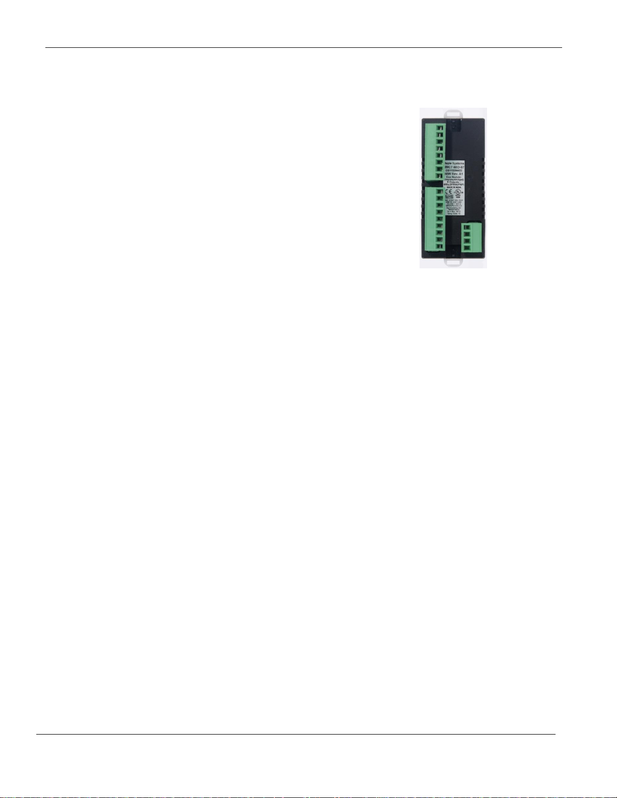
HMC7-MIO-07 (8 Bidirectional Input, 6 Relay, 2 Sourcing Output
Digital Module)
This module is a digital input/output module for the HMC7000
Series models. It has eight bidirectional inputs and six relay
outputs (3 per common), plus two sinking digital outputs. Four
of the inputs can be configured as high speed counters (HSC)
using the MW registers (see below). When used as HSCs, input
X0 (channel 1), X5 (channel 2), X2 (channel 3), and X7
(channel 4) are used to record the incoming pulses. The
sourcing outputs support PWM.
Phone: 425/745-3229 • Fax: 425/745-3429 • Email: maple@maplesystems.com • www.maplesystems.com .
1010-1043 Page 54 of 85 Rev. 02, 11/08/2013
Page 56
HMC7000 Series I/O Module Guide
Power
3.9 VDC from HMC7000 base
Approvals
CE, UL
Digital Inputs
8 bidirectional inputs
Rated input voltage
24 VDC
Rated input current
Up to 5mA
Input impedance
4.9K ohms
Minimum ON voltage
15 VDC
Maximum OFF voltage
5 VDC
Turn ON Time
10 msec
Turn OFF Time
10 msec
Isolation
Optically isolated from internal circuit
Connection method
Removable terminals (3.81 mm pitch)
High Speed Channels
No. of inputs
4 channels (X0 and X5, X2 and X7)
Maximum Input Frequency
25 KHz
Maximum Input Count
4,294,967,295 (32-bit)
Digital Outputs
6 relay, 2 sourcing outputs (PNP-type)
Output Capacity (PNP)
500mA per output maximum
Output Capacity (relay)
2A per contact, 6A per common
Rated load
500mA @ 24VDC (250 mA PWM)
High Speed Channels
No. of Outputs
2 channels (Y2 and Y4)
General
Operating Temperature
0 to 55°C
Operating Humidity
10% to 90% (non condensing)
Mechanical Dimension (LxWxH)
3.11x1.18x1.42 inches [79x30x36mm]
Input Power Supply
Input Voltage
24VDC
Input Current
4A maximum
Specifications:
Phone: 425/745-3229 • Fax: 425/745-3429 • Email: maple@maplesystems.com • www.maplesystems.com .
1010-1043 Page 55 of 85 Rev. 02, 11/08/2013
Page 57

HMC7000 Series I/O Module Guide
For connecting to high-speed inputs:
For connecting to normal inputs:
For connecting to PWM outputs:
For connecting to relay outputs:
Wiring:
Phone: 425/745-3229 • Fax: 425/745-3429 • Email: maple@maplesystems.com • www.maplesystems.com .
1010-1043 Page 56 of 85 Rev. 02, 11/08/2013
Page 58

HMC7000 Series I/O Module Guide
Function
Register
Access
X0-X7 Inputs
Xnn000-007 (XWnn00)
Rd Only
Y0-Y7 Outputs
Ynn000-007 (YWnn00)
Rd/Write
High Speed Counter
Option
HSC Ch. 1
HSC Ch. 2
HSC Ch. 3
HSC Ch. 4
HSC Input
X0 (terminal)
Xnn000 (reg)
X5 (terminal)
Xnn005 (reg)
X2 (terminal)
Xnn002 (reg)
X7 (terminal)
Xnn007 (reg)
Rd Only
HSC Reset Input
X1 (terminal)
Xnn001 (reg)
X6 (terminal)
Xnn006 (reg)
X3 (terminal)
Xnn003 (reg)
X4 (terminal)
Xnn004 (reg)
Rd Only
HSC Output Flag
Y1 (terminal)
Ynn001 (reg)
Y6 (terminal)
Ynn006 (reg)
Y7 (terminal)
Ynn007 (reg)
Y0 (terminal)
Ynn000 (reg)
Rd/Write
HSC Configuration
Register
MWnn00
MWnn06
MWn112
MWn118
Rd/Write
HSC Counter Register
(Current Value)
MWnn01
MWnn02
MWnn07
MWnn08
MWnn13
MWnn14
MWnn19
MWnn20
Rd/Write
HSC Preset Register
MWnn03
MWnn04
MWnn09
MWnn10
MWnn15
MWnn16
MWnn21
MWnn22
Rd/Write
HSC Enable Bit
Mnn080
Mnn176
Mnn272
Mnn368
Rd/Write
HSC Reset Bit
Mnn081
Mnn177
Mnn273
Mnn369
Rd/Write
Quadrature Inputs
Pair 1
Pair 2
Counter Inputs
X0, X5
X2, X7
Rd Only
Counter Reset Input
X1
X3
Rd Only
Output Flag
Y1
Y7
Rd/Write
PWM Outputs
PWM1
PWM2
Output
Y2
Y4
Rd Only
Configuration:
Use MAPware-7000 to assign input (X and XW), output (Y and YW), and configuration (M and MW) memory
addresses to the module. These addresses are created according to the slot location of the module, where nn refers
to the slot number (ex. 01…05):
Phone: 425/745-3229 • Fax: 425/745-3429 • Email: maple@maplesystems.com • www.maplesystems.com .
1010-1043 Page 57 of 85 Rev. 02, 11/08/2013
Page 59

HMC7000 Series I/O Module Guide
Input Mode
Output Mode
Register Value
Normal Input
N/A 0
High Speed,
Single Phase,
Up Counter
Output ON when preset is reached
2
Output ON when counter is enabled,
OFF when preset is reached
258
Quadrature 1X
Output ON when preset is reached
3
Output ON when counter is enabled,
OFF when preset is reached
259
Quadrature 2X
Output ON when preset is reached
67
Output ON when counter is enabled,
OFF when preset is reached
323
Quadrature 4X
Output ON when preset is reached
131
Output ON when counter is enabled,
OFF when preset is reached
387
Reference the table below when configuring each HSC Configuration Register:
To implement High Speed Counter Operation:
22. Connect a device that will provide the high speed pulses to one of the four High-Speed inputs on the
expansion module.
23. Configure the HSC using the configuration register for that channel.
24. Write the HSC preset count value in the Preset register for that channel.
25. Enable the HSC by setting the HSC Enable Bit that channel.
26. HSC increments the current value register for that channel until the preset value is reached.
27. Enable the HSC Reset Bit by setting for that channel. This will cause the HSC current value to reset back
to 0.
28. To start the process again, simply reset (clear) the HSC Reset Bit and set the HSC Enable Bit. Note: if the
HSC Enable Bit is still ON, you must reset (clear) this bit, and then set it again.
Phone: 425/745-3229 • Fax: 425/745-3429 • Email: maple@maplesystems.com • www.maplesystems.com .
1010-1043 Page 58 of 85 Rev. 02, 11/08/2013
Page 60

HMC7000 Series I/O Module Guide
Function
Register
Description
Output
Y2
Y4
Physical Output
Configuration Register
MWnn24
MWnn30
Value = 1 for this mode
Frequency Setting Register1
MWnn25
MWnn26
MWnn25
MWnn26
Range = 1 to 10000
ON Duty Setting Register
MWnn27
MWnn28
MWnn31
MWnn32
Range = 0 to 100
Output Enable Flag
MWnn36_0
MWnn36_1
Enabled when ON
ON Duty Setting Error Flag
MWnn29_2
MWnn29_7
ON = error (resets automatically)
Frequency Setting Error Flag
MWnn29_3
MWnn29_3
ON = error (resets automatically)
Function
Register
Description
Output
Y2: CW
Y4: CCW
Physical Output
Configuration Register
MWnn24
Value = 3 for this mode
Frequency Setting Register
MWnn25
MWnn26
Range = -10000 to -1;
1 to 10000
Output Enable Flag
MWnn36_0
Enabled when ON
Frequency Setting Error Flag
MWnn29_3
ON = error (resets automatically)
Reference the tables below when configuring the PWM outputs:
Normal PWM
Note 1: Both PWM outputs must run at the same frequency.
CW/CCW
Phone: 425/745-3229 • Fax: 425/745-3429 • Email: maple@maplesystems.com • www.maplesystems.com .
1010-1043 Page 59 of 85 Rev. 02, 11/08/2013
Page 61

HMC7000 Series I/O Module Guide
Function
Register
Description
Output, PWM Pulse
Y2
Physical Output
Output, PWM Direction
Y4
Configuration Register
MWnn24
Value = 7 for this mode
Frequency Setting Register
MWnn25
MWnn26
Range = -10000 to -1;
1 to 10000
Output Enable Flag
MWnn36_0
Enabled when ON
Frequency Setting Error Flag
MWnn29_3
ON = error (resets automatically)
Function
Register
Description
Output, PWM Pulse
Y2
Physical Output
Configuration Register
MWnn24
Value = 9 for this mode
Minimum Frequency Register
MWnn25
MWnn26
Range = 1 to 10000
Maximum Frequency Register
MWnn27
MWnn28
Range = 1 to 10000
Acceleration Time Register
MWnn37
Range: 0 to 32767
Deceleration Time Register
MWnn39
Range: 0 to 32767
Total Pulses Register
MWnn41
MWnn42
0 to 2147483647
Elapsed Pulses Register
MWnn45
MWnn46
0 to 2147483647
Output Enable Flag
MWnn36_0
Enabled when ON
Frequency Setting Error Flag
MWnn29_3
ON = error (resets automatically)
Acceleration Time Error Flag
MWnn29_4
ON = error
Deceleration Time Error Flag
MWnn29_5
ON = error
Total Pulses Setting Error Flag
MWnn29_6
ON = error
Total Pulses Reached
MWnn49_0
ON when Total Pulses have been
sent
Pulse/Direction
Fixed Pulse Mode
Phone: 425/745-3229 • Fax: 425/745-3429 • Email: maple@maplesystems.com • www.maplesystems.com .
1010-1043 Page 60 of 85 Rev. 02, 11/08/2013
Page 62

HMC7000 Series I/O Module Guide
To implement PWM Operation:
19. Configure the PWM output using the configuration register for that channel and mode.
20. Set the parameters values for the selected mode. Monitor the error flags for the parameters.
21. Enable the output by setting the Enable Output that channel.
22. HSC increments the current value register for that channel until the preset value is reached.
23. Enable the HSC Reset Bit by setting for that channel. This will cause the HSC current value to reset back
to 0.
24. To start the process again, simply reset (clear) the HSC Reset Bit and set the HSC Enable Bit. Note: if the
HSC Enable Bit is still ON, you must reset (clear) this bit, and then set it again.
Phone: 425/745-3229 • Fax: 425/745-3429 • Email: maple@maplesystems.com • www.maplesystems.com .
1010-1043 Page 61 of 85 Rev. 02, 11/08/2013
Page 63

HMC7000 Series I/O Module Guide
Power
3.75 VDC from HMC7000 base
Approvals
CE, UL
Analog Inputs
4 Inputs, each configurable as:
0 to 50mV, 0 to 100 mV; 0 to 10V, 0 to 5V, -10 to +10V;
0 to-20mA, 4-20mA;
PT100 RTD, alpha1 [0.00385 Ω/Ω/°C] (-200 to 850 C);
PT100 RTD, alpha2 [0.003926 Ω/Ω/°C] (-100 to 457 C);
PT1000 RTD (-200 to 850 C);
Type J Thermocouple (-210 to 1200 C);
Type K Thermocouple (-200 to 1373 C)
Resolution
16 bit
Input Impedance
V, mV, Thermocouple RTD inputs: 1 MΩ;
mA: 100Ω
Maximum Input
+/- 30VDC, 30mA
Accuracy
Overall Accuracy 1% of full scale (max)
Analog Outputs
2, each configurable as:
0 to 5v, 0 to 10V;
0 to 20mA, 4-20mA
Accuracy
Overall Accuracy 1% of full scale (max)
Load
1 KΩ (Min) for V;
500Ω (Max) for mA
General
Connection method
Removable terminals (3.81 mm pitch)
Operating Temperature
0 to 55°C
Operating Humidity
10% to 90% (non-condensing)
Mechanical Dimension (LxWxH)
3.11x1.18x1.42 inches [79x30x36mm]
HMC7-MIO-08 (4 Input Analog / 2 Analog Output Module)
This module is an analog input/output module for the
HMC7000 Series models. It has four universal analog inputs,
which can measure
0 to 50mV, 0 to 100 mV;
0 to 10V, 0 to 5v, -10 to +10V;
0 to-20mA, 4-20mA;
PT100 RTD (alpha1, alpha2), PT1000 RTD;
Type J, K Thermocouple (15-minute warm-up recommended)
It also has two analog outputs, configurable as
0 to 5V, 0 to 10V;
0 to 20mA, 4 to 20mA;
Specifications:
Phone: 425/745-3229 • Fax: 425/745-3429 • Email: maple@maplesystems.com • www.maplesystems.com .
1010-1043 Page 62 of 85 Rev. 02, 11/08/2013
Page 64
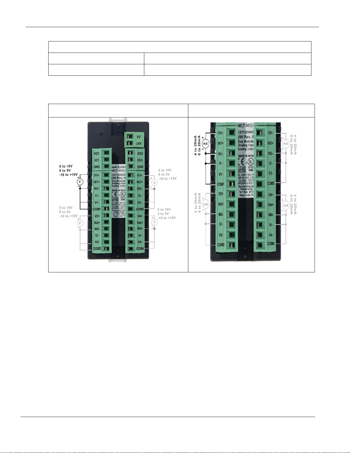
HMC7000 Series I/O Module Guide
Input Power Supply
Input Voltage
24VDC
Input Current
80mA (max)
For connecting to analog voltage inputs:
Connecting to analog current inputs:
Wiring:
Phone: 425/745-3229 • Fax: 425/745-3429 • Email: maple@maplesystems.com • www.maplesystems.com .
1010-1043 Page 63 of 85 Rev. 02, 11/08/2013
Page 65

HMC7000 Series I/O Module Guide
For connecting to RTD inputs:
For connecting to mV/thermocouple inputs:
For connecting to voltage outputs
For connecting to current outputs
Phone: 425/745-3229 • Fax: 425/745-3429 • Email: maple@maplesystems.com • www.maplesystems.com .
1010-1043 Page 64 of 85 Rev. 02, 11/08/2013
Page 66

HMC7000 Series I/O Module Guide
Register
Description
Access
XWnn00
Input Channel 1 Data
Read Only
XWnn01
Input Channel 2 Data
Read Only
XWnn02
Input Channel 3 Data
Read Only
XWnn03
Input Channel 4 Data
Read Only
YWnn00
Output Channel 1 Data
Read/Write
XWnn01
Output Channel 2 Data
Read/Write
MWnn00
Input Channel 1 Configuration Register
Read/Write
MWnn01
Input Channel 2 Configuration Register
Read/Write
MWnn02
Input Channel 3 Configuration Register
Read/Write
MWnn03
Input Channel 1 Configuration Register
Read/Write
MWnn04
Output Channel 1 Configuration Register
Read/Write
MWnn05
Output Channel 2 Configuration Register
Read/Write
MWnn10
Analog Input Error Register
Read/Write
15
14
13
12
11
10
09
08
07
06
05
04
03
02
01
00
Unused
Unused
Unused
Unused
Ch 4 Open Thermocouple
Ch 4 Open RTD
Unused
Ch 3 Open Thermocouple
Ch 3 Open RTD
Unused
Ch 2 Open Thermocouple
Ch 2 Open RTD
Unused
Ch 1 Open Thermocouple
Ch 1 Open RTD
Unused
Configuration:
Use MAPware-7000 to assign input (XW) and configuration (MW) memory addresses to the module.
These addresses are created according to the slot location of the module, where nn refers to the slot
number (ex. 01…05):
Analog Input Error Register Bit Assignment
Phone: 425/745-3229 • Fax: 425/745-3429 • Email: maple@maplesystems.com • www.maplesystems.com .
1010-1043 Page 65 of 85 Rev. 02, 11/08/2013
Page 67

HMC7000 Series I/O Module Guide
Input Channel
Signal Type
Value
Voltage, 0 to 10V
1
Voltage, 0 to 5V
6
Voltage, -10 to +10V
18
Voltage, 0 to 50mV
5
Voltage, 0 to 100mV
4
Current, 4 to 20mA
2
Current, 0 to 20mA
3
RTD, PT100, alpha11
7
RTD, PT100, alpha21
8
RTD, PT1000
9
Thermocouple, Type J2
14
Thermocouple, Type K2
15
Output Channel
Signal Type
Value
Voltage, 0 to 10V
2
Voltage, 0 to 5V
1
Current, 4 to 20mA
5
Current, 0 to 20mA
6
Reference the table below when configuring each Input Configuration Register (MWnn00-MWnn03):
Notes:
1. alpha1= 0.00385 Ω/Ω/°C, alpha2=0.003926 Ω/Ω/°C
2. 15-minute module warm-up time recommended
Reference the table below when configuring each Output Configuration Register (MWnn04-MWnn05):
Phone: 425/745-3229 • Fax: 425/745-3429 • Email: maple@maplesystems.com • www.maplesystems.com .
1010-1043 Page 66 of 85 Rev. 02, 11/08/2013
Page 68

HMC7000 Series I/O Module Guide
Power
24VDC ± 15%, 3W
Approvals
CE, UL
Digital Inputs
12 bidirectional inputs
Rated input voltage
24 VDC
Rated input current
Up to 5mA
Input impedance
4.9K ohms
Minimum ON voltage
15 VDC
Maximum OFF voltage
5 VDC
Turn ON Time
10 msec
Turn OFF Time
10 msec
Isolation
Optically isolated from internal circuit
Connection method
Removable terminals (3.81 mm pitch)
High Speed Channels
No. of inputs
2 channels (X1 and X2)
Maximum Input Frequency
25 KHz
Maximum Input Count
4,294,967,295 (32-bit)
Digital Outputs
6 relay outputs, 2 sinking outputs (NPN-type)
Output Capacity
2A per output (relay)
500mA per output (NPN)
Rated load
500mA @ 24VDC
Total output capacity
2A @ 24VDC
HMC7030A-L (12 digital inputs and 8 digital outputs built-in)
This unit has built-in I/O. It has 12 directional
inputs, 6 relay outputs and 2 sinking NPN
outputs.
Specifications:
Phone: 425/745-3229 • Fax: 425/745-3429 • Email: maple@maplesystems.com • www.maplesystems.com .
1010-1043 Page 67 of 85 Rev. 02, 11/08/2013
Page 69

HMC7000 Series I/O Module Guide
General
Operating Temperature
0 to 50°C
Operating Humidity
10% to 90% (non condensing)
Mechanical Dimension (LxWxH)
5.04x4.02x1.77 inches [128x102x45mm]
Panel Cutout
4.69x3.55 inches [119x93mm]
For connecting to bidirectional inputs:
Connecting to outputs:
Wiring:
Phone: 425/745-3229 • Fax: 425/745-3429 • Email: maple@maplesystems.com • www.maplesystems.com .
1010-1043 Page 68 of 85 Rev. 02, 11/08/2013
Page 70

HMC7000 Series I/O Module Guide
Function
Register
Access
X0-X11 Inputs
X00000-011 (XW0000)
Rd Only
Y0-Y7 Outputs
Y00000-007 (YW0000)
Rd/Write
High Speed Counter Option
HSC Channel 1
HSC Channel 2
HSC Input
X1(terminal)
X00001 (reg)
X2(terminal)
X00002 (reg)
Rd Only
HSC Reset Input
X4(terminal)
X00004 (reg)
X5(terminal)
X00005 (reg)
Rd Only
HSC Output Flag
Y0(terminal)
Y00000 (reg)
Y1(terminal)
Y00001 (reg)
Rd/Write
HSC Configuration Register
MW0010
MW0020
Rd/Write
HSC Counter Register
(Current Value)
MW0011
MW0012
MW0021
MW0022
Rd/Write
HSC Preset Register
MW0013
MW0014
MW0023
MW0024
Rd/Write
HSC Enable Bit
M00240
M00400
Rd/Write
HSC Reset Bit
M00241
M00401
Rd/Write
Bits
Function
15-4
Not used
3
0 : Falling Edge
1 : Rising Edge
2, 1, 0
Module Operating
Mode :
000 : Normal Operation
010 : Up Counter HSC
Configuration:
Use MAPware-7000 to assign input (X and XW), output (Y and YW), and configuration (M and MW) memory
addresses to the module. These addresses are created according to the slot location of the module, where nn refers
to the slot number:
Reference the table below when configuring each HSC Configuration Register (MW0010 and MW0020):
To implement High Speed Counter Operation:
1. Connect a device to X1 (Channel 1) or X2 (Channel 2) that will provide the high speed pulses to the
expansion module.
2. Configure for HSC mode using the configuration register MW0010 (Channel 1) or MW0020 (Channel 2).
3. Write the HSC preset count value in MW0013 (Channel 1) or MW0023 (Channel 2).
4. Enable the HSC by setting the HSC Enable Bit M00240 (Channel 1) or M00400 (Channel 2).
5. HSC increments (starting from 0) the current value register in MW0011 (Channel 1) or MW0021 (Channel
2) until the preset value is reached. Then HSC sets Y0 (Channel 1) or Y1 (Channel 2).
Phone: 425/745-3229 • Fax: 425/745-3429 • Email: maple@maplesystems.com • www.maplesystems.com .
1010-1043 Page 69 of 85 Rev. 02, 11/08/2013
Page 71

HMC7000 Series I/O Module Guide
6. Enable the HSC Reset Bit by setting M00241 (Channel 1) or M00401 (Channel 2). Or by setting Reset Pin
X4 (Channel 1) or Reset Pin X5 (Channel 2). This will cause the HSC current value to reset back to 0 and
the output Y0 (Channel 1) or output Y1 (Channel 2) will reset (clear) to 0.
7. To start the process again, simply reset (clear) the HSC Reset Bit and set the HSC Enable Bit. Note: if the
HSC Enable Bit is still ON, you must reset (clear) this bit, and then set it again.
Phone: 425/745-3229 • Fax: 425/745-3429 • Email: maple@maplesystems.com • www.maplesystems.com .
1010-1043 Page 70 of 85 Rev. 02, 11/08/2013
Page 72

HMC7000 Series I/O Module Guide
Common Terms for I/O Modules
This section defines some common terms used to describe various types of input and output
modules. The terms explained below are generic descriptions. Be sure to consult the datasheet
for the specific requirements when installing and wiring a module.
Digital Modules
Digital Modules provide physical connections and interpretations of input devices using discrete
signals. The input is represented in the PLC input registers as a 1 for the on state and 0 for the
off state. Each digital input terminal is associated with an internal Input Coil (X) in the tag
database of the HMC7000. Similarly, each digital output terminal is associated with an Output
Coil (Y).
Analog Modules
Analog Modules provide physical connections and interpretations of input devices using analog
signals. The input range depends on the type of input device. Configure analog inputs to work
with current or voltage sources. Each analog input terminal is associated with an internal Input
Register (XW) in the tag database of the HMC7000. Similarly, each analog output terminal is
associated with an Output Register (YW).
Sinking versus Sourcing Inputs
These terms refer to the type of digital inputs or outputs used. A sourcing I/O provides a voltage
source, and a sinking I/O provides a ground. Any module that is not bidirectional (meaning
current can go in either direction) requires that the circuit conduct current in a specific direction.
For a sourcing module, the current flows out of the expansion module terminal and into the
common (signal ground) terminal. The term source indicates the terminal on the expansion
module provides the current to the switch contact or load.
For a sinking module, the current flows into the expansion module terminal and out of the
common terminal on the I/O module. The term sink indicates the terminal takes in the current
from the switch contact or load.
Phone: 425/745-3229 • Fax: 425/745-3429 • Email: maple@maplesystems.com • www.maplesystems.com .
1010-1043 Page 71 of 85 Rev. 02, 11/08/2013
Page 73

HMC7000 Series I/O Module Guide
PNP-type connection (Source)
NPN-type connection (Sink)
Note: arrow indicates current flow direction
In order to have current flow, each I/O terminal on the expansion module must have a return path
or a signal ground connection. In most modules, multiple I/O terminals share the signal ground
connection.
Digital Outputs (PNP or NPN type)
The output terminals of a digital I/O module use an optically isolated PNP or NPN transistor to
energize the connected load. PNP/NPN outputs are faster than relay outputs but can only work
with low current DC loads (typically 500mA max per terminal). PNP modules are sourcing
modules, and NPN modules are sinking modules.
Note: the above diagrams show that a PNP output is ‘sourcing’ current and the NPN output is
‘sinking’ current.
Phone: 425/745-3229 • Fax: 425/745-3429 • Email: maple@maplesystems.com • www.maplesystems.com .
1010-1043 Page 72 of 85 Rev. 02, 11/08/2013
Page 74

HMC7000 Series I/O Module Guide
Digital Outputs (Relay type)
The output terminals of a relay-type digital module typically control loads that require an AC
power source:
Use a Relay Output module to connect a DC load that requires more current than the maximum
available when using a PNP or NPN output. For AC loads, each relay output contact can handle
up to 230VAC with a 2A load per contact. For DC loads, each relay output contact can handle a
2A load per contact for up to 30VDC.
Analog I/O
The analog I/O modules interpret analog signals and write a value to a register in the HMC. The
analog modules are configurable to sense or output current or voltage signals.
Analog Voltage
Analog inputs can measure DC voltage ranges of -10 to +10 volts and 0 to 10 volts. With analog
inputs, the analog module writes a data value to the assigned register (XW) based upon the
measured DC voltage at the input. Analog outputs can provide 0 to 10 VDC with a minimum
resistance of 1000 ohms depending upon the value in the assigned register (XY). I/O resolution
is 12-bits.
Analog Current
Analog inputs can measure DC current ranges from 0 to 20mA and 4 to 20mA. With analog
inputs, the analog module writes a data value to the assigned register (XW) based upon the
measured DC current at the input. The analog outputs can provide 0 to 20mA and 4 to 20mA.
Analog outputs can deliver a DC current of up to 20mA to a load with a maximum resistance of
500 ohms based upon the data value in the assigned register (XY). I/O resolution is 12-bits.
I/O Terminals
Each I/O terminal is labeled for easy identification on the modules. As mentioned above, ‘COM’
is the common ground terminal. A terminal with an ‘X’ followed by a number is an input
terminal and a terminal with a ‘Y’ followed by a number is an output terminal. The number
refers to the position associated with each terminal on the I/O module.
When a project is created in MAPware-7000, bit/register memory addresses are assigned for
each terminal on the expansion module. MAPware-7000 provides the option to allow the
software to do this automatically. In this case, it will assign memory addresses according to the
position and expansion slot in which the I/O module is located.
Phone: 425/745-3229 • Fax: 425/745-3429 • Email: maple@maplesystems.com • www.maplesystems.com .
1010-1043 Page 73 of 85 Rev. 02, 11/08/2013
Page 75

HMC7000 Series I/O Module Guide
In addition, many of the I/O modules have a two-pin connector that is used to connect a voltage
source (usually +24VDC). This voltage source drives the output terminals of the I/O modules.
Installing I/O Modules
The expansion modules for the HMC7000 snap onto the back of the HMC7000 thru expansion slots. The
HMC7030A-M and HMI7035A-M units support up to three modules. The HMC7057A-M unit supports
up to five modules.
Configuring the I/O Modules
The I/O expansion modules for the HMC7000 Series are assigned to the proper slot using MAPware-
7000. Note that any project downloaded into a HMC7000 with modules that do not match the physical
configuration of the unit will not run. Therefore, it is important to correctly identify the I/O modules in
the MAPware-7000 project.
Regardless of the particular HMC7000 model used, the steps to configure the I/O modules are very
similar:
1. Open a new project and select the appropriate HMC7000 model. Click OK.
2. On the Project Configuration dialog box, enter the appropriate information and then click OK.
3. In the Project Information Window, click on the I/O Allocation folder, and then click on the
Expansion folder.
4. Double-click on Slot 1 to display the I/O Allocation dialog:
Phone: 425/745-3229 • Fax: 425/745-3429 • Email: maple@maplesystems.com • www.maplesystems.com .
1010-1043 Page 74 of 85 Rev. 02, 11/08/2013
Page 76

HMC7000 Series I/O Module Guide
5. Select from the list box, the particular I/O expansion module installed in Slot 1 of the HMC7000.
When the checkbox to ‘Add tags for XW, YW, and MW’ is checked, MAPware-7000
automatically assigns tags to the Tag Database for the I/O module. The tags configured are based
upon the module and the slot location. Click OK.
6. In this example, Slot1 is identified with an IO module, along with a description and memory
address allocation. The tags are available in the Tag Database as seen below. These tags can be
used in the project to address the I/O.
Phone: 425/745-3229 • Fax: 425/745-3429 • Email: maple@maplesystems.com • www.maplesystems.com .
1010-1043 Page 75 of 85 Rev. 02, 11/08/2013
Page 77

HMC7000 Series I/O Module Guide
Register/ Bit
Description
Configuration
Register
The 16-bit register that controls how the High-Speed counter operates.
Bits 3-0 are used (see below)
Current Count
Register
The 32-bit register that counts the number of times that the Trigger has transitioned. The
specified register is the Least Significant Word (LSW); the next consecutive register is
the Most Significant Word (MSW).
Preset Register
The 32-bit register that defines the number of counts at which the Done bit will be set
(see description of Done Bit below). The specified register is the Least Significant Word
(LSW); the next consecutive register is the Most Significant Word (MSW).
Trigger Bit
The input bit that triggers the count. The counter will increment by one on each bit
transition. The counter can operate on a falling (default) or rising edge.
Enable Bit
The counter will not run unless this bit is set. If this bit is reset while the counter is
running, the current values will be maintained, but the Trigger bit will have no effect.
The Done bit is reset if the Enable bit is reset. If the Current Count value is greater than
or equal to the Preset value, the Done bit is set after the Enable bit is set again.
Reset Bit
When this bit goes from false to true, the current count will reset to 0 and the Done bit is
reset. The reset occurs even when the Enable bit is reset. The reset is accomplished by
an internal bit or a physical input.
Done Bit
The physical output that turns on when the Current Count is equal to or greater than the
Preset value. The bit remains set until the Reset bit goes true, even if the counter counts
beyond the preset. If the Enable bit is reset, the Done bit will reset. If the Enable bit is
set while the Current Count is equal to or greater than the Preset, the Done bit is set.
Configuration of the HMC7000 Series High Speed Counters
Maple Systems’ HMC products have built-in High-Speed counters that link directly to specific inputs and
outputs. Specific registers and bits are predefined for setup and control of these counters. No logic is
required to run the counters, other than logic that may be used to configure and control the counters.
Two inputs on the module are used as the Triggers for the High-Speed counters, and two outputs are used
as the Done bits. The inputs support a maximum speed of 25 KHz.
The following bits and registers are associated with a High-Speed counter:
Phone: 425/745-3229 • Fax: 425/745-3429 • Email: maple@maplesystems.com • www.maplesystems.com .
1010-1043 Page 76 of 85 Rev. 02, 11/08/2013
Page 78

HMC7000 Series I/O Module Guide
Bit
Description
15-4
Reserved (leave set to 0)
3
Edge Trigger:
0 = Falling
1 = Rising
2,1,0
Counter Mode:
000 =High Speed Counter Off
010 = High Speed Up Counter
Other settings are reserved.
Function
Counter 1
Counter 2
Trigger Bit
X00001
X00002
Done Bit
Y00000
Y00001
Enable Bit
M00240
M00400
Reset Bit (Internal, Physical)
M00241, X00004
MW401, X00005
Configuration Register
MW0010
MW0020
Current Count Register (LSW, MSW)
MW0011, MW0012
MW0021, MW0022
Preset Register (LSW, MSW)
MW0013, MW0014
MW0023, MW0024
Configuration Register
Note: You can write to the configuration register value using the Power-Up logic block or in a Power-Up
Task.
Specific High Speed Counter Registers
The registers and I/O associated with the High-Speed Counter depend on the hardware.
For products with Built-In I/O (HMC7030A-L)
Phone: 425/745-3229 • Fax: 425/745-3429 • Email: maple@maplesystems.com • www.maplesystems.com .
1010-1043 Page 77 of 85 Rev. 02, 11/08/2013
Page 79

HMC7000 Series I/O Module Guide
Function
Counter 1
Counter 2
Trigger Bit
X n000
Xn005
Done Bit
Yn001
Yn006
Enable Bit
Mn080
Mn176
Reset Bit (Internal, Physical)
Mn081, Xn001
Mn177, Xn006
Configuration Register
MWn00
MWn06
Current Count Register (LSW, MSW)
MWn01, MWn02
MWn07, MWn08
Preset Register (LSW, MSW)
MWn03, MWn04
MWn09, MWn10
These tags are assigned automatically when a project is created:
For products with Modular I/O (Requires the HMC7-MIO-01 or HMC7-MIO-02 module
)1
Notes:
1. n is the slot in which the module is installed.
Phone: 425/745-3229 • Fax: 425/745-3429 • Email: maple@maplesystems.com • www.maplesystems.com .
1010-1043 Page 78 of 85 Rev. 02, 11/08/2013
Page 80

HMC7000 Series I/O Module Guide
Function
Counter 1
Counter 2
Trigger Bit
X03000
X03005
Enable Bit
M03080
M03176
Done Bit
Y03001
Y03006
Reset Bit (Internal, Physical)
M03081, X03001
M03177, X03006
Configuration Register
MW0300
MW0306
Current Count Register (LSW, MSW)
MW0301, MW0302
MW0307,
MW0308
Preset Register (LSW, MSW)
MW0303, MW0304
MW0309,
MW0310
For example, a module installed in Slot 3 has the following assignments:
These tags are assigned automatically when the module is added to the project.
Phone: 425/745-3229 • Fax: 425/745-3429 • Email: maple@maplesystems.com • www.maplesystems.com .
1010-1043 Page 79 of 85 Rev. 02, 11/08/2013
Page 81

HMC7000 Series I/O Module Guide
Click System parameters
from the Define menu
Check the
checkbox.
Some Sample Ladder Logic
These two rungs configure the High Speed Counters in a unit that has built-in I/O.
The HMC ladder logic requires an input condition on each rung. The input bits are the Normally Closed
contacts of an otherwise unused bit. The Move Word instructions write a value of 2 (00000010b) to the
Configuration Register of each High Speed Counter. This sets Bit 1 and leaves all other bits reset. Each
counter is configured as a High Speed Up Counter, with the trigger being on the falling edge.
The trigger is configured by Bit 3 of the Configuration Word. To configure the trigger as a rising edge,
write 10 (00001010b) to the Configuration Register.
Retaining the High Speed Counter Values
The Count and Preset values are normally lost when power is removed from the HMC. However, the
System Parameters dialog has an option to retain the Count and Preset values.
Retain High Speed Counter
Phone: 425/745-3229 • Fax: 425/745-3429 • Email: maple@maplesystems.com • www.maplesystems.com .
1010-1043 Page 80 of 85 Rev. 02, 11/08/2013
Page 82

Maple Systems Inc.
Web: www.maplesystems.com
808 134th Street SW, Suite 120
Everett, WA 98204-7333
Phone: (425) 745-3229
Email: maple@maplesystems.com
© 2011 Maple Systems Inc. All rights reserved.
 Loading...