

Page 1

Quick Start Guide
HMC3070A-M
Description:
HMC3070A-M 800x480 pixels, 7.0” color TFT, with three
expansion slots.
Contents:
—1 HMC3070A-M (in plastic bag with protective cover sheet
on the screen)
—1 plastic bag containing 4 mounting clamps (each clamp
consisting of cap nut, bolt, and clamp)
—1 three prong green power plug*
—Cardboard package inserts
—Quick Start Guide
*Note: Connector manufacturer may vary.
Programming software (MAPware-7000), cables, and power
supply purchased separately.
Panel Mounting and Panel Cutout:
HMC3070A-M
Tighten the mounting screws evenly to a torque between 0.4 Nm to
maintain water and dust resistance. Make sure the panel is not dirty
and warped and that it is strong enough to hold the unit.
Note: Maximum Panel thickness (on which unit is to be mounted)
should be 6.0 mm (Tolerance: +/-0.2 mm).
Doc. No. 1011-0302
Maple Systems, Inc. 808 134th St SW, Suite 120, Everett, WA 98204-7333 www.maplesystems.com
Specifications:
The HMC3070A-M is a combination operator-based HMI (Human
Machine Interface) with built-in PLC (Programmable Logic
Controller) operation. It communicates with external PLCs over
serial communications ports to read/write data. Three I/O
expansion modules can be attached.
Power: 24VDC +/- 15%, 20W (with 3
expansions)
Display: 7.0” TFT (800 x 480 pixels)
Color graphics display
Bezel: NEMA 4X (IP 66) rated
Touchscreen: 4-wire analog resistive
LEDs: Power indicator
CPU: 32-bit RISC, 454 MHz
Memory: 45 MB Max. Application Memory
Serial Comms (DE9S): Two serial ports
(RS232/RS485/RS422)
USB Slave (Micro Type B): Upload/download projects
USB Host (Standard Type A): Data storage
Ethernet (RJ45): 10/100 Mbps
SD card: Micro SD (high capacity- 4 to 32
GB)
Expansion ports: Three for optional HMC3 I/O
modules
Operating temp: 0 to 60° C
Humidity: 10% to 90% (non-condensing)
Dimensions (WxHxD): 7.32 x 5.43 x 1.22 inches
[186.0 x 138.0 x 31.0mm]
Panel cutout: 4.37 x 3.15 inches [111 x 80mm]
Mounting Module to Panel:
Step 2: Tighten clamps evenly to prevent warping. Continue to
tighten until a torque force of 0.4-0.5 Nm is obtained.
Step 3: HMC3070 should be aligned evenly with the cutout with
no warping present after clamps are tightened.
Port Details:
Note: connect shell to shield of cable.
Grounding:
The HMC3070 should have a good electrical connection to earth
ground via the power connector for safety and to reduce electrical
noise. The HMC unit should be grounded separately from other
high-power systems.
Note: Do not use a ground connection that has potential
impedance (such as painted screws) or is subject to vibration.
Expansion I/O Modules:
The HMC3070A-M has three expansion slots that you can use to
connect I/O modules. Below is a listing of modules currently
available (consult Maple Systems website for additional
information).
HMC3-M1616P: 16 digital input, 16 PNP-type digital
output
HMC3-M1614Y: 16 digital input, 14 digital output
(12 relay, 2 PNP-type)
HMC3-M1212P0200: 12 digital input, 12 PNP-type digital
output, 2 analog input
HMC3-M1212Y0200: 12 digital input, 12 digital output
(10 relay, 2 PNP-type), 2 analog
input
HMC3-M1210P0201: 12 digital input, 10 PNP-type digital
output, 2 analog input and 1 analog
output.
HMC3-M1210Y0201: 12 digital input, 10 digital output (8
relay, 2 PNP-type), 2 analog input,
and 1 analog output.
HMC3-M0808P0401T: 8 digital input, 8 PNP-type digital
output, 4 analog input and 1 analog
output.
HMC3-M0808Y0401T: 8 digital input, 8 digital output (6
relay, 2 PNP-type), 4 analog input,
and 1 analog output.
Rev 02, 06/25/2018
COM1 COM2
Pin
Number
Name D escription
1 RX- RS422 receive -
2 TX- RS422 transmit -
3 RX+ RS422 receive +
4 TX+ RS422 transmit +
5 GND Ground
6 RXD RS232 receive
7 TXD RS232 transmit
Pin
Number
Name D escription
1 TX+ RS422 transmit +
2 TXD RS232 transmit
3 RXD RS232 receive
4 RX+ RS422 receive +
5 GND Ground
6 NC No connection
7 NC No connection
8 TX- RS422 transmit -
9 RX- RS422 receive -
Page 2
Doc. No. 1011-0302
Rev 02, 06/25/20148Maple Systems, Inc. 808 134th St SW, Suite 120, Everett, WA 98204-7333 www.maplesystems.com
Getting Started:
Perform the following steps to configure and use the HMC3000
Series unit:
1. Install MAPware-7000 software.
2. Create your project.
3. Connect a programming cable (USB or Ethernet).
4. Save your project.
5. Download project to HMC3070 (note: you must select the
Download Firmware option for the initial download).
6. The HMC3000 unit is ready to use in the system.
PC Requirements for MAPware-7000:
Processor: 1 GHz Pentium-based processor or equivalent
Operating System: Microsoft Windows 7 or 10
RAM: 1 GB
Hard Disk: 800 MB (including 200 MB for the .NET Framework
Redistributable)
Display: 1024x768 high color 16-bit
Mouse/Keyboard: Required
USB or Ethernet port: for project downloads
Installing the Software:
1. Insert MAPware-7000 CD into CD-ROM drive and follow
instructions.
2. If software installation does not automatically start, click
\SETUP.EXE from CD directory.
PLC Connecting Cables:
Contact Maple Systems to order any PLC Communications
Cables or to download a cable pinout diagram.
Additional Resources:
Detailed instructions on the operation and installation of the
HMC3000 Series are available in the HMC3000 Programming
Manual that is included with the MAPware-7000 configuration
software. MAPware-7000 also includes help files that provide
detailed information on using the configuration software.
Other Sources (visit Maple Systems Support Center website):
—Controller Information Sheets- specific information on
connecting a particular manufacturer's PLC to the HMC3000
—Cable Drawings- wiring diagrams to particular PLCs
—Technical Notes- Provides additional information and examples
not covered in the operations manual
—Software Upgrades- Upgrades to the MAPware-7000 software
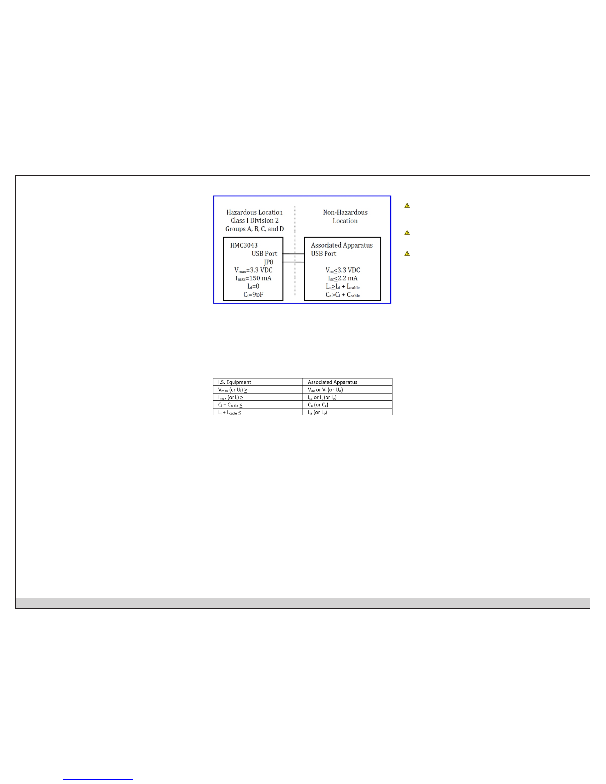
Class I Division 2 Wiring Considerations:
Capacitance and inductance of the field wiring from the
nonincendive equipment to the associated apparatus shall be
calculated and must be included in the system calculations as
shown in Table 1.
Where the cable capacitance and inductance per foot are not
known, the following values shall be used: Ccable = 60 pF/ft,
Lcable = 0.2 µH/ft.
TABLE 1:
Wiring method must be in accordance with ANSI/NFPA70.
This equipment is suitable for use in Class I, Division 2, Groups A,
B, C and D or non-hazardous locations only.
WARNING – EXPLOSION HAZARD – Do not disconnect
equipment unless power has been removed or the area is known
to be non-hazardous.
WARNING – EXPLOSION HAZARD - Substitution of
components may impair suitability for Class I, Division 2.
WARNING - CAUTION, battery may explode if mistreated. Do
not recharge, disassemble or dispose of in fire.
It is recommended that the user periodically inspect the sealed
devices used, check for any degradation of properties, and
replace as necessary.
For Technical Support:
Please contact Maple Systems if you have any questions
regarding this product. We ask that you provide us with the unit
serial number and firmware revision number written on the
product label of the unit.
Maple Systems Inc.
808 134th St. SW, STE 120
Everett, WA 98204
Tel: 425-745-3229
Fax: 425-745-3429
Email: support@maplesystems.com
Website: www.maplesystems.com
 Loading...