

Page 1

Page 2

COPY RIGHT NO TICE
This manual is a publication of Maple Systems, Inc., and is provided for use by its customers only. The contents of the
manual are copyrighted by Maple Systems, Inc.; reproduction in whole or in part, for use other than in support of Maple
Systems equipment, is prohibited without the specific written permission of Maple Systems.
The copyright of EasyBuilder-5000 and its related software belongs to Weintek Labs, Inc.
WAR RANTY
Maple Systems warrants each product to be free from electrical and mechanical defects in materials and workmanship for a
period of two years from the date of shipment. This warranty does not apply to defects in the Products caused by abuse,
misuse, accident, casualty, alteration, negligence, repair not authorized by Maple Systems, use on current or voltages other
than specified by Maple Systems, or application or installation not in accordance with published instruction manuals. This
warranty is in lieu of any other warranty either expressed or implied.
Maple Systems’ liability is limited to the repair or replacement of the Product only, and not costs of installation, removal, or
damage to user’s property or other liabilities. If Maple Systems is unable to repair or replace a nonconforming Product, it
may offer a refund of the amount paid to Maple Systems for such Product in full satisfaction of its warranty obligation.
Maximum liability of Maple Systems is the cost of the Product.
Information furnished by Maple Systems, Inc., is believed to be accurate and reliable. However, no responsibility is assumed
by Maple Systems for the use of this information nor for any infringements of patents or other rights of third parties which
may result from its use. No license is granted by implication, or otherwise, under any patent or patent rights of Maple
Systems, Inc. Maple Systems retains the right to revise or change its products and documentation at any time without notice.
IF SER VICE IS RE QUIRED
Contact Watlow Customer Service at (507) 454-5300 for instructions on how to return a product and how to obtain a Return
Materials Authorization (RMA) number.
Package the unit in its original packaging container or, if unavailable, any suitable rigid container. If a substitute container is
used, surround the unit with shock absorbing material; damage in shipment is not covered by the warranty. Include a letter
with the unit describing the difficulty and designating a contact person.
All returns will be tested to verify customer claims of noncompliance with the product warranty. Improper return packaging,
which makes verification impossible, will void the warranty. Products passing the tests will be returned “AS IS” to the
customer.
If noncompliance is verified and is not due to customer abuse or the other exceptions described with product warranty, Maple
Systems will, at its option, repair or replace the Product returned to it, freight prepaid , which fail to comply with the
foregoing warranty, provided Maple Systems is notified of such noncompliance within the two-year warranty period.
AP PLI CA TIONS AS SIS TANCE
This man ual is de signed to pro vide the nec es sary in for ma tion for trou ble-free in stal la tion and op er a tion of your new Op er a tor
In ter face Ter mi nal (OIT). How ever, if you need as sis tance, please call Watlow at (507) 494-5656 between 7 a.m. and 5 p.m.
Central Standard Time (CST). Ask for an Applications Engineer. Or you may e-mail your questions to
wintechsupport@watlow.com .
Page 3

Ta ble of Con tents
EZware-5000 Sup port ...............1
OIT Mod els Sup ported ............1
PLCs Sup ported .................1
About Your Doc u men ta tion............1
Con ven tions ...................1
What You Need .................2
OIT Ba sics ........................2
What is a Sil ver Se ries OIT? ........4
List of Fea tures..................5
Chap ter 1 - In stal la tion of OITs ............7
Un pack ing the Unit ..............7
Man ag ing Elec tro static Dis charge ....7
CE Com pli ance .................7
NEMA Rat ing ...................7
En vi ron men tal Con sid er ations ......7
Safety Pre cau tions ...............8
Con trol Panel De sign Guide lines........8
Con trol Panel Ground ing ..........9
Con nect OIT Chas sis Ground to Con trol
Panel.........................9
Power Sup ply Se lec tion............11
Ca ble Rout ing and Noise Im mu nity...11
In stal la tion........................12
Con nect the OIT to Power .........12
Panel Prep a ra tion ...............14
Mount the OIT to the Panel.........14
Con fig u ra tion Wir ing ................15
Con nect the OIT to the PC for
Con fig u ra tion ..................15
Chap ter 2 - OIT Lo cal Setup...............17
Fac tory Con fig u ra tion................17
Cal i brat ing the Touchscreen ........17
Get ting into Lo cal Setup ...........17
Chang ing the Sys tem Set tings .......18
View ing Sys tem In for ma tion ........22
Trans fer ring Pro jects and Data from
USB/CompactFlash ..............23
Chap ter 3 - Con nect the OIT to the PLC or
Con trol ler ............................25
COM Ports for the
HMI5080/HMI5104/HMI5121 ......26
COM Ports for the HMI5056 .......27
Con nect ing to COM1 and COM3 on
Port A ........................28
Con nect ing to COM1 and COM2 on
Port B ........................32
Con nect ing mul ti ple PLC/con trol lers
se ri ally us ing daisy chain ing ........33
Con nect ing one or more PLC/con trol lers
via Ethernet ....................33
Chap ter 4 - Cre at ing Your First Pro ject ......35
Be fore You Be gin ...................35
Con nect ing OIT to Com puter ..........35
Start ing EZware-5000 ...............35
Cre at ing a Sam ple Pro ject ............36
Set ting the Sys tem Pa ram e ters ......36
Cre at ing a Popup Win dow .........40
Cre at ing a Startup Win dow ........48
Fin ish ing Up ......................54
Chap ter 5 - Sim u la tor Mode ..............59
The Sim u la tion Screen ...............59
Chap ter 6 - Us ing EZware-5000 ...........61
Over view .........................60
The Pro ject Man ager ................60
Com mu ni ca tions & Pass word Set tings . 62
Ed i tor Set tings ..................63
Trans fer Set tings ................63
Sim u la tion Set tings...............63
View ing Data Log................65
Easy Printer ....................70
Con vert ing Data/Event Log.........70
Rec ipe Ex tended Mem. Editor .......71
Pass Through Mode ..............76
The EasyConverter Ap pli ca tion .........76
Man ag ing Pro jects ...............78
Ed it ing and Cre at ing Screen Ob jects..82
Ba sic Ed it ing Commands ..........86
Group ing Ojects ................90
Lay er ing Objects ................91
Nudg ing Objects ................93
Mak ing Ob jects Same Size .........97
Mak ing Ob jects Same Color........98
Gen eral Set tings ................101
Au to mat i cally Re boot OIT .............112
Save and Com pile the Pro ject ..........112
Chap ter 7 - Cre at ing Win dows ............116
Win dow Fun da men tals ...............117
Open ing a Win dow ..............117
Cre at ing a New Win dow ..........117
As sign ing Un der lay Win dows .......121
How to Dis play Un der lay Win dows ...122
Rules That Ap ply to Un der lay
Win dows ......................122
De let ing a Win dow ..............123
Us ing Base Win dows ................123
How to Dis play Base Win dows ......123
Us ing the Com mon Win dow ...........129
Chang ing the Ac tive Com mon
Win dow.......................132
Us ing the Fast Se lec tion Win dow........133
Us ing the Fast Se lec tion Key ........135
Chang ing screens us ing the Fast
Se lec tion win dow ................136
Sys tem Mes sage Win dow ..........138
Chap ter 8 - Cre at ing Graphic Ob jects .......140
Draw ing Ob jects ...................140
Us ing the Draw ing Tools ..........140
Us ing Text .....................144
Page 4

ii Sil ver Se ries In stal la tion & Operation Man ual
Pre de fined Shapes and Pic tures.........146
Us ing a Pre de fined Shape ......146
Us ing a Pre de fined Pic ture ......148
Graphics Li brar ies ..................150
What are ‘states’? ............150
Us ing Shape Li brar ies .........150
Us ing Pic ture Li brar ies .........154
Us ing Group Li brar ies .........157
Us ing Sound Li brar ies .........160
Chap ter 9 - Cre at ing and Us ing Da ta bases and
Lan guages ............................164
Cre at ing and Us ing the Tag Li brary .....164
Im port ing and Ex port ing the Tag
Li brary.....................165
Us ing the Tag Li brary..........165
Cre at ing the La bel Li brary ............166
Set ting Dif fer ent Fonts for Dif fer ent Lan -
guages ....................168
Im port ing and Ex port ing the La bel
Li brary.....................169
Us ing the La bel Li brary...............169
Us ing Lan guages with the La bel
Li brary.....................170
Chap ter 10 - Rep re sent ing Data with Graphics
Ob jects...............................172
Gen eral Prop er ties of Objects ..........172
Us ing In dex Registers ................182
Us ing In ter nal Data Mem ory of OIT .....184
Rep re sent ing PLC Coil Reg is ters ........192
The Bit Lamp Ob ject ..........192
The Set Bit Ob ject ............196
The Tog gle Switch Ob ject .......197
Rep re sent ing PLC Data Reg is ters ........199
The Word Lamp Ob ject ........199
The Set Word Ob ject ..........202
The Slider Ob ject .............203
The MultiState Switch Ob ject.....205
The Nu meric Dis play Ob ject.....209
The Nu meric In put Ob ject ......211
The ASCII Dis play Ob ject .......216
The ASCII In put Ob ject.........217
The Mov ing Shape Ob ject ......218
The An i ma tion Ob ject .........222
The XY Plot Ob ject ............224
Chap ter 11 - Us ing and Cre at ing Keypads ...240
How to Cre ate a Key pad .............240
Dis play ing and Us ing a Key pad ........241
Chap ter 12 - Bar Graphs, Me ters and Trends . 246
Cre at ing Bar Graphs ................246
Cre at ing Me ter Dis plays ..............248
Cre at ing Trend Dis plays & Data Sam pling
Ob jects ..........................251
His tory Data Dis play Part .......258
Chap ter 13 - Cap tur ing Alarms and Events ...264
Us ing Alarms ......................264
Mon i tor ing Alarms with the Alarm/Event
Log .............................263
Dis play ing Alarms/Alarm Dis play Ob ject ..266
Dis play ing Alarms us ing the Alarm Bar
Ob ject.....................267
Us ing Events ................269
Mon i tor ing Events With the Event Log
Ob ject.....................269
Dis play ing Events Us ing the Event
Dis play Ob ject ...............269
Chap ter 14 - Data and Rec ipe Trans fer Ob jects 272
Us ing the Data Trans fer Ob ject.........271
Us ing the Rec ipe Trans fer (Data Trans fer, Trig -
ger Based) Ob ject ..................272
Cre at ing a Rec ipe ............273
Backup Part .................274
Chap ter 15 - Mac ros ....................277
Us ing Mac ros .....................277
Macro Sam ple and
Im ple men ta tion .............277
Vari ables, Dec la ra tions and Mem ory
Us age ...........................278
Mem ory Us age: .............278
Vari able Dec la ra tions..........279
Vari able Ini tial iza tion ..........279
Ar ray ini tial iza tion ............280
Re served Words ..............281
Op er a tor...................281
Or der of Pre ce dence ..........282
Main Func tions and Sub-
func tions ...................282
Lo cal and Global Vari ables .....282
Cre at ing Vari able Ar rays .......283
Us ing Mac ros Within Rec i pes ....283
State ments, Con di tions &
Ex pres sions .................284
Func tion Calls and Pass ing Pa ram e ters
246
Read ing & Writ ing Ex ter nal Reg is ters in
a Macro ...................286
Pre cau tions, Tips & Tricks when Us ing
Mac ros ....................288
Com piler Er rors & Er ror Codes .........288
Chap ter 16 - Mis cel la neous Objects.........291
Misc. Objects ......................291
Sched uler Object ............293
Time Set Tab ................293
Pro hibit Tab .................295
Me dia Player ................296
In dex ................................303
1010-1007, Rev 06
Page 5

Sil ver Se ries In stal la tion & Op er a tion Man ual
iii
1010-1007W, Rev 06
Page 6

Introduction 1
Introduction - Welcome
Welcome to the Maple Systems’ Silver Series Operator Interface Terminals (OITs) from Watlow. Using graphic OITs has
never been easier. This powerful family of graphics operator interface terminals connect to Watlow controllers and other
devices such as programmable logic controllers (PLCs) to provide the human-machine interface in industrial applications.
The Silver Series has several features not found in other graphic OITs. This manual explains the operation of the Silver
Series OITs and how to implement the many available features using the EZware-5000 Configuration Software.
Watlow and Maple Systems have worked together to bring you this product. Please contact Watlow for support, and be sure
to utilize any resources referenced in this manual on the Watlow website (www.watlow.com) and the Maple Systems
Website (www.maplesystems.com).
EZware-5000 Sup port
OIT Mod els Sup ported
For the latest list of Silver Series Models supported by Watlow, please visit the Watlow website at www.watlow.com.
PLCs Supported
For the latest list of PLCs and controllers supported by the Silver Series OITs, please visit our website.
About Your Doc u men ta tion
Maple Systems provides many resources to allow you to get the most out of your Silver Series OIT.
· Silver Series Operation Manual (shipped with EZware-5000 as a PDF file) - describes installation, general operation
and features of the Silver Series using EZware-5000 configuration software..
· Watlow Silver Operator Interface Terminal Manual Addendum - contains specific instructions and examples on
communicating with and creating interfaces for Watlow controllers.
· Controller Information Sheets - important information specific to each supported protocol.
· EZware-5000 On-line Help - covers the operation of EZware-5000. Always available by clicking HelpTopics from
the Help menu in EasyBuilder, or press F1 from any dialog.
For more information about these and other training sources, visit the Maple Systems website.
Con ven tions
When using EZware-5000, there are usually several ways to perform a task. For example, if you want to copy a graphics
object, you can:
· Click the Copy command on the Edit menu.
· Click the Copy button on the Standard toolbar.
· Press the CTRL + C keys on your com puter.
1010-1007W, Rev 06
Page 7

2 Sil ver Se ries In stal la tion & Operation Man ual
In most cases, we will describe each method when the task is first discussed. The menu method is then used whenever the
task is used in later procedures. Other conventions used in this manual are listed in the following table.
Convention Meaning
Bold
Italic
ALL CAPITALS Directory names, file names, key names, and acronyms
KEY1+KEY2
click Refers to clicking the primary mouse button (usually the left mouse button) once.
Double-click Refers to quickly clicking the primary mouse button (usually the left mouse button) twice.
Right-click
Characters that you must type exactly as they appear. For example, if you are directed to type a:\setup,
you should type all the bold characters exactly as they are printed.
Placeholders for information you must provide. For example, if you are directed to type filename, you
should type the actual name for a file instead of the word shown in italic type. Italics are also used to
indicate a glossary term.
A plus sign (+) between key names means to press and hold down the first key while you press the second
key.
Refers to clicking the secondary mouse button (usually the right mouse button) once. Right-clicking
usually opens shortcut menus.
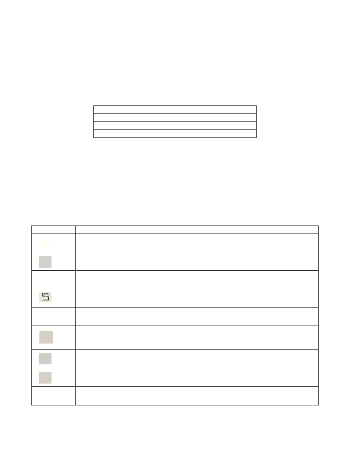
The following table identifies symbols and margin icons.
Icon Meaning
4 Identifies a procedure.
4 Indicates a reference to additional information.
Indicates an important note.
What You Need
The following items are needed to configure and operate your OIT.
Configuration Software EZware -5000
Configuration Cable
Personal Computer
Power Cable 6030-0009 2-conductor 18 AWG, shielded, no connectors
24VDC Power Supply User Provided
PLC User Provided
Controller Information Sheet
Communication Cable
(HMI to PLC)
1
Al lows you to con nect OIT directly to PC Ethernet port or to USB port to download/upload projects into the OIT.
2
Computer requirements include a Pentium 1.7 GHz or higher processor, 512 MB RAM, 200 MB available Hard Disk
1
2
7431-0104 ( Ethernet Crossover cable for HMI5056T, HMI5080T, HMI5104T/XH, HMI5121T/X, HMI5150X
models)
7431-0115 (USB download cable for HMI5043N, HMI 5056N, HMI5070NH/TH and HMI5100N/T models)
User Provided
Maple Systems provides Controller Information Sheets which contain important information specific to each
PLC. Please locate the sheet that corresponds to your PLC on our website.
Refer to our web site (www. maple-systems.com) for a list of available cables.
Space, SVGA or higher resolution monitor, Keyboard and Mouse, available Ethernet port or USB port (for downloading
project), at least one RS232 port for online simulation, Windows XP, 2000 or Vista.
OIT Ba sics
Operator Interface Terminals (OITs) provide much more versatility than traditional mechanical control panels. An OIT
allows a plant floor operator to monitor current conditions of a control system and, if necessary, to initiate a change in the
operation of the system. OITs connect to programmable logic controllers (PLCs) typically through the PLC’s serial
communications port. The OIT can be programmed to monitor and/or change current values stored in the data memory of the
PLC.
OITs can have either text-based or graphics-based displays. A text-based OIT can display printable text characters but no
graphics. Some text-based OITs can display text characters in various sizes. A graphics-based OIT can display printable text
characters of varying fonts and sizes and graphics shapes such as icons, bitmaps, or pictures. Using pictures instead of words
or characters often greatly simplifies the operation of the OIT, making the OIT much more intuitive to use.
1010-1007W, Rev 06
Page 8

Introduction 3
Some OITs use touchscreen displays while others use a membrane-style keypad. Membrane-style keyboards are best used in
applications in which the keypad is likely to become dirty. Touchscreen displays are placed over the OIT screen thus
providing much more flexibility than typical membrane-style keypads. Because of this, switches can be created on a
touchscreen that appear only when needed.
The Maple Systems Silver Series OITs are graphics-based touchscreen OITs. Before we get any further into the operation of
these OITs, it is necessary to define some terms that will be used throughout this manual.
Projects
The OIT has two basic segments of internal memory. The code memory contains the information required by the OIT that
controls how it operates such as the features supported and how it communicates to a PLC. The OIT programmer does not
have the ability to change code memory. The project memory pertains to all of the window screens created and any other
features that the OIT programmer can create using the EZware-5000 configuration software. Therefore, the term project is
used to designate the file that is sent to the OIT from the EZware-5000 software.
Objects
An object is any action that the OIT performs while it is communicating to the PLC. In order to get the operator interface
terminal to ‘do anything’, you must program the OIT with objects. Objects perform actions such as display text or graphics,
write a value to a PLC register, or display an alarm. Objects most often are graphics shapes that are to be displayed on the
OIT screen. For example, a Text Object is used to display text on the OIT. But objects are also used to configure the OIT to
perform some action. For example, a PLC Control Object tells the OIT to continuously monitor a PLC register that is used
by the PLC to request a new window. Some objects can display a graphics shape on the OIT screen and
perform some
action. For example, a Toggle Switch Object creates a graphic object on the OIT that when pressed, activates a bit in the
PLC.
Graphics Object
A graphics object is any text, icon, or picture that can be displayed on the OIT. Graphics objects are further defined by how
they are composed or created. A Text Object is a graphics object that displays text on the OIT screen. A Bitmap Object is a
graphics object that displays a bitmap on the OIT screen. Bitmaps are files stored in the OIT to display pictures. A Shape
Object is a graphics object that displays a shape on the OIT screen. Shapes are also files stored in the OIT to display
pictures. Shapes differ from bitmaps in that shapes are stored using a vector-based file format whereas bitmaps use a
pixel-based file format. Each format has its advantages and disadvantages. We will not go into any more detail about bitmap
objects and shape objects until later in this manual. For now, think of them as objects used to display pictures on the OIT
screen. Finally, a Group Object is the most complex type of graphics object. It is a combination of other objects. Briefly, a
group object consists of one or more objects that are ‘grouped’ together and stored as one object. A good example is a
keypad, which is really a combination of several keys each designed to perform a specific task. When grouped together, a
keypad can be stored as a group object for use in other projects or windows.
Windows
A window is a screen that can be displayed on the OIT. Windows can be full-sized to completely cover the OIT display or
partially sized. Any partially sized window is usually referred to as a popup window. Windows can appear on the OIT
display by a request from the PLC or by a press from the touchscreen. Windows can be configured to any size. Once a
window is displayed, it can be moved around the OIT display, removed from the display, or minimized to an icon. Windows
can even overlap each other. Each window can display graphics objects and there is no limit to the number of graphics
objects that can be placed on each window. The Silver Series is capable of storing up to 1999 windows , but the actual limit
is determined by the total amount of memory used for the application. A more in-depth discussion of windows is covered in
later chapters. For now, think of windows as screens that can be displayed on the OIT.
1010-1007W, Rev 06
Page 9
4 Sil ver Se ries In stal la tion & Op er a tion Man ual
What is a Silver Series OIT?
The Silver Series OITs by Maple Systems are graphics operator interfaces designed to connect to PLCs in an industrial
environment. The displays are covered with analog resistive touchscreens designed for harsh industrial environments. The
touchscreens use the latest in touchscreen technology enabling the OIT programmer to create switches that are very fine in
resolution. Unlike many other touchscreen OITs on the market, the Silver Series OITs are not limited to a fixed number of
cells in which switches can be created. The OIT programmer can create as many switches of varying sizes and shapes as he
wishes, limited only by the total amount of memory available for the project.
Three LED indicators are provided on the face of the Silver Series OITs to provide instant feedback to the OIT operator of
the current operating condition of the OIT.
LED Indicator Purpose
PWR LED (yellow) indicates if power is applied to the OIT
CPU LED (green) indicates if the OIT is operating correctly
COM LED (red) indicates communications activity on PLC port
The Silver Series OITs have three serial ports, which provide a connection to a PLC using RS-232 or
RS-485 communications and an Ethernet connection for PLC communication and project upload and download. The serial
ports also provide the ability to use the EZware-5000 configuration software in Simulation Mode enabling the OIT
programmer to test his project on the PC instead of downloading the project to the OIT.
The Silver Series is powered using +24VDC. Finally, a reset switch is provided on the back of the OIT to reinitialize the
OIT if an operational failure occurs. The Silver Series is designed for industrial environments and carries a NEMA 4X
(indoor only) rating as well as CE compliance for noise immunity and emissions.
List of Fea tures
The next chapter will guide you through the creation of your first project. Before you proceed, you may wish to read this
brief list of some of the features offered in the Silver Series OIT.
Icon Name Description
Bit Lamp
Word Lamp Creates a graphics object to reflect the current state of a multi-state PLC data register.
Set Bit
Set Word
Toggle Switch
Slider Object
Multi-State
Switch
Creates a graphics object to reflect the current status of a PLC bit.
Creates a touchscreen graphics object that represents a two-state switch. When pressed it
sets/resets a PLC bit.
Creates a touchscreen graphics object that represents a multi-state switch. When pressed it can
place a constant value in a PLC register or jog the value.
Creates a touchscreen graphics object that represents a two-state switch changing state
(picture) based upon a PLC bit. When pressed, it can control another PLC bit.
Creates a touchscreen graphics object that changes the state according to the position of a
slider switch.
Creates a multi-state touchscreen graphics object that changes state (picture) according to the
value in a PLC data register. When pressed, it sends a value(s) to another PLC register.
1010-1007W, Rev 06
Function Key Creates a touchscreen graphics object or runs a macro.
Numeric Input
Displays a number stored in a PLC register. The number can be changed using a numeric
keypad.
Page 10

Introduction 5
Numeric Data
ASCII Input
ASCII Data Displays ASCII characters stored in a PLC register.
Moving Shapes
Animation
Indirect Window
Direct Window Displays a Window based on a bit in a PLC register.
Alarm Displays Creates alarms to display alarms sent from the Alarm/Event Log Object.
Alarm Bar Displays alarms detected by the Alarm/Event Log Object on a single horizontal scrolling line.
Displays a number stored in a PLC register.
Displays ASCII characters stored in a PLC register. Characters can be changed using an
alphanumeric keypad.
Creates a multi-state graphics object, which changes state (picture) and position on the screen
according to a value in a PLC register.
Creates a multi-state graphics object, which changes state (picture) on the screen according to a
value in a PLC register. The positions on the screen are predefined.
Configures the OIT to monitor PLC data registers to display for a specific window popup by a
PLC word address
Data Transfer
(triggered)
Data Transferred
(time-based)
Event Displays Displays messages detected in the Alarm/Event Log and can acknowledge the message(s).
Data Sampling
(Data Logging)
Alarm/Event Log Contains the data for detecting alarm conditions.
Trend Displays
Bar Graph
Displays
Meter Displays Creates a scale meter.
Recipe Transfer Transfers data to the specified PLC registers.
System
Message
Transfers data to the specified PLC registers based on a touch or PLC bit status.
Transfers data to the specified PLC registers on a timed basis.
Stores data for trending and archiving.
Creates a trend graph. Samples data in a single or multiple 16-bit PLC register and plots the
data on a time graph.
Creates a bar graph with alarm monitoring.
Customizes the content of system-generated messages.
PLC Control Configures the OIT to monitor PLC data registers to display full window screens.
History Data
Display
Displays historical data in a tabular format.
1010-1007W, Rev 06
Page 11

6 Sil ver Se ries In stal la tion & Operation Man ual
Backup Copies recipe, event or historical data to one of the USB memory devices.
Data Block
Display
XP Plot Creates an XY Plot.
Media Player Displays a video file.
Option List Creates a drop-down list blox
Scheduler Peforms an action based upon a time schedule.
Displays the data in a series of registers as a line graph.
1010-1007W, Rev 06
Page 12

In stal la tion of OITs 7
Chapter 1 - Installation of OITs
Be fore You Be gin
Please read the following for proper handling of your new OIT.
Un packing the Unit
Carefully unpack the OIT. Please read any instructions or cautions that appear on the shipping container. Check all
material in the container against the enclosed packing list. Maple Systems, Inc. will not accept responsibility for
shortages against the packing list unless notified within 30 days. The equipment and its accessories were inspected
and tested by Maple Systems before shipment; all of the equipment should be in good working order. Examine the
equipment carefully; if any shipping damage is evident, notify the carrier immediately. You are responsible for
claim negotiations with the carrier. Save the shipping container and packing material in case the equipment needs to
be stored, returned to Maple Systems, or transported for any reason.
Man aging Elec tro static Dis charge
It is best NOT to remove the rear enclosure of the OIT. When the rear part of the enclosure is removed, the circuitry
inside is exposed to possible damage by electrostatic discharge during handling. Minimize the possibility of
electrostatic discharge by:
• Discharging personal static by grounding yourself prior to handling the OIT
• Handling the OIT at a static-free grounded workstation
• Connecting the frame ground (FG) connector of the OIT to a clean earth ground
• Placing the OIT in an anti-static bag during transport
CE Com pli ance
The Silver Series OITs have been tested to conform to European CE requirements per Council Directive
89/336/EEC. The European Union created these requirements to ensure conformity among products traded in those
countries. Specifically, the Silver Series OITs meet or exceed the noise emissions and immunity requirements as set
forth in the EN50081 (Emissions) and EN50082 (Immunity) standards. These products are designed to withstand
electrical noise in harsh ind ustrial environments. They also conform to requirements that limit electrical emissions.
However, this does not guarantee that the products will be totally immune from possible malfunction in cases where
severe electrical noise occurs. Therefore, we strongly recommend that you follow the guidelines outlined in this
chapter for proper wire routing and grounding to insure the proper operation of the Silver Series OIT.
NEMA Rat ing
The Silver Series OITs are rated for NEMA 4X/12 (indoor only) or IP65 installations. This means that when the
OIT is properly mounted to a panel or other enclosure, the front enclosure of the OIT will provide protection to the
inside of the panel from splashing water, wind blown dust, rain, or hose-directed water. The OIT must be installed
according to the instructions in this chapter to be properly sealed.
En vi ron men tal Con sid er ations
The Silver Series is designed to operate in temperatures from 0-45° C. It is intended for indoor installations and not
designed for outdoor applications. Avoid installing the Silver Series in environments with severe mechanical
vibration or shocks. Do not install the OIT in enclosures with rapid temperature variations or high humidity. Either
will cause condensation of water inside the device and eventual damage to the OIT.
1010-1007W, Rev 06
Page 13
8 Sil ver Se ries In stal la tion & Op er a tion Man ual
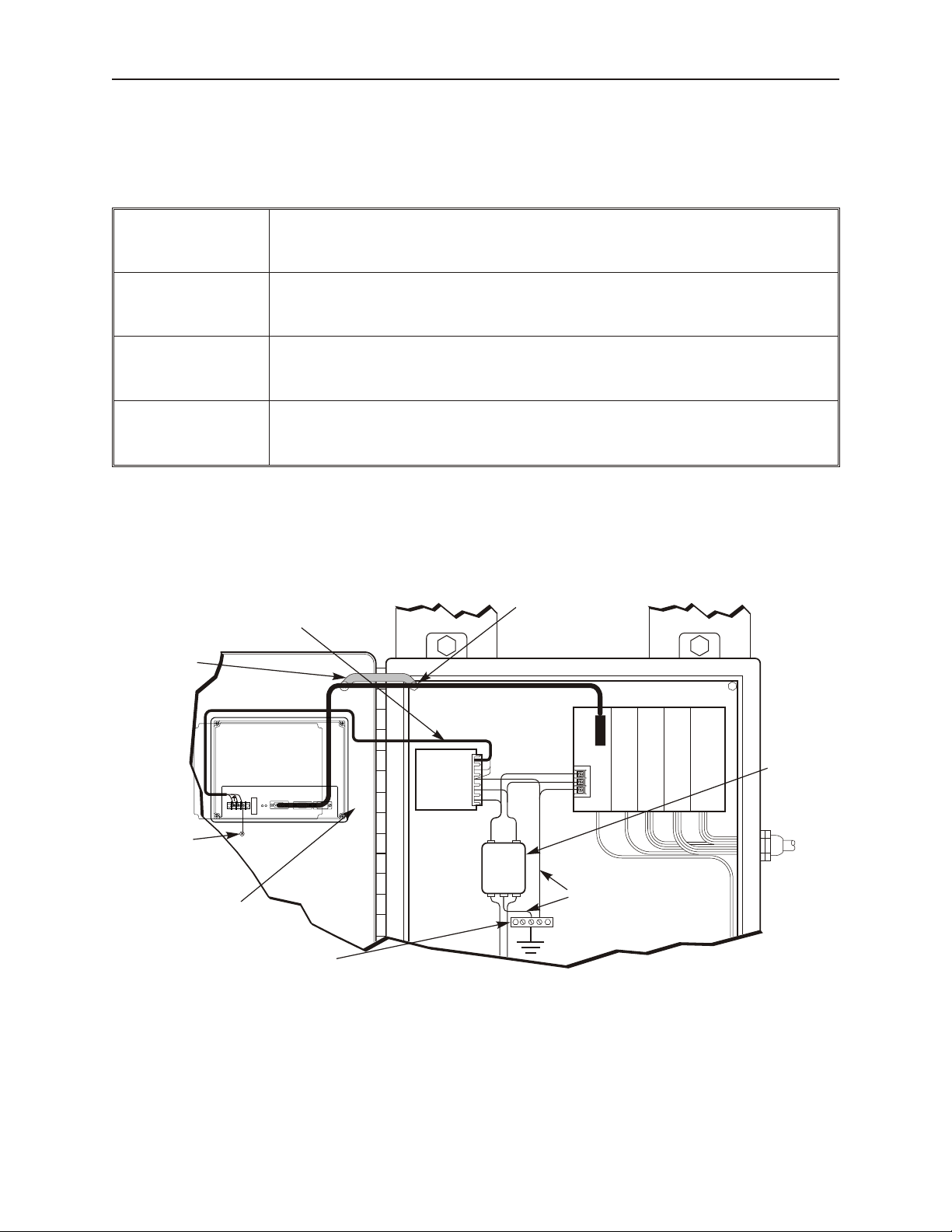
I / O control lines
PLC/Host
Ground wires
(rear side)
OIT is
grounded to
control panel
Ground
strap
Power
line
filter
Quiet ground
(isolated)
Quiet ground
Line
Filter
OIT
Power
Supply
Shielded power cable
Shielded
communication
cable
Control panel is
tied to a reliable
earth ground
Silver Series
OIT
24V
GND
COM1 [RS-485 2/4W]
PLC [RS-232]
COM3 [RS-485]
COM3 [RS-232]
COM1 [RS-232]
COM2 [RS-232]
Safety Pre cau tions
Please observe the following precautions when installing the Silver Series OIT. Failure to comply with these
restrictions could result in loss of life, serious personal injury, or equipment damage.
Warning: Do not operate the OIT in areas subject to explosion due to flammable gases,
vapors, or dusts.
Warning: Do not connect the OIT to an AC power source. You will cause permanent damage
to the OIT.
Warning: Do not attempt to use a DC power supply that does not meet OIT power
requirements. You may cause malfunction or permanent damage to the OIT.
Warning: Do not power the OIT with a DC power supply used for inductive loads or for input
circuitry to the programmable logic controller. Severe voltage spikes caused by these devices may
damage the OIT.
Con trol Panel De sign Guide lines
Pay careful attention to the placement of system components and associated cable routing. These items can
significantly enhance the performance and integrity of your control application.
Con trol Panel Ex am ple
1010-1007W, Rev 06
Page 14

In stal la tion of OITs 9
Frame ground (marked FG)
Stud or screw
Area on panel free of paint
Control panel
(connected to earth ground)
Con trol Panel Grounding
The control panel should be connected to a good, high-integrity earth ground both for safety considerations and
shielding purposes. Maple Systems cannot overemphasize the importance of good grounding. If you fail to use
good grounding procedures during installation, sporadic malfunction of the OIT may occur:
· Connect the OIT’s chassis ground terminal to a reliable earth ground with a low-resistance path.
· Route all earth ground wires that lead from the OIT, the PLC, the power supply, and the line filter to a
central earth ground point such as a barrier strip. This will ensure that no ground current from one device
influences the operation of the other devices.
· Connect the OIT chassis ground terminal to the control panel door using a heavy-gauge short braided cable
or ground wire to minimize resistance.
· Connect the power cable’s shield wire to the OIT’s chassis ground terminal.
· Connect the control panel to earth ground using a copper grounding rod close to the OIT and control panel.
Hinged doors on control panels do not provide a long-term electrical connection to the rest of the enclosure.
Corrosion develops over time and prevents good electrical contract. For this reason, a separate wire braid should be
installed from the hinged control panel to the rest of the enclosure.
For a more in-depth overview of ground wiring techniques, refer to technical note #1027, “OIT Ground Wiring and
Electrical Noise Reduction,” which you can find on our web site.
Con nect OIT Chas sis Ground to Con trol Panel
To reduce the possibility of electrical interference, con nect the chassis ground terminal of the OIT to a clean earth
ground. If the control panel is metal, make sure it is properly grounded. Then connect a short heavy-gauge wire
(#18 AWG) from the chassis ground terminal of the OIT to a mounting bolt on the control panel door. The
mounting bolt must have good electrical contact to the control panel; scrape away any paint that may be covering
the panel to provide a good connection.
If the control panel is made of a non-conductive material, it is essential that you connect the chassis ground terminal
of the OIT to a clean earth ground point located close to the panel.
Typ i cal Chas sis Con nec tion
1010-1007W, Rev 06
Page 15

10 Sil ver Se ries In stal la tion & Op er a tion Man ual
Power Sup ply Se lec tion
The power supply used to power the OIT should provide an output of +24 VDC 5% measured at the OIT power
terminal block. A 24VDC regulated power supply dedicated to the OIT is required. Consult the datasheet of your
particular OIT for current requirements.
The power cable for the OIT should be 18AWG, 2-conductor wire with a shield drain wire and protective shield
(foil or braid). The shield drain wire must be connected to earth ground at both ends of the cable. Please refer to the
“Connect the OIT to Power” section for more information.
A power line filter installed at the AC input to the OIT power supply is highly recommended as a safeguard against
conducted RF noise, which is often present on factory power lines. The wires connecting the output of the power
line filter to the power supply should be kept as short as possible to minimize any additional noise pickup. The case
of the power line filter should be connected to a quiet earth ground. The power line filter should have a current
rating of at least 3 Amps with common mode and differential mode attenuation.
Do not use the power supply used to provide power to the OIT to power switching relays, solenoids, or other active
devices.
Power Line Fil ter Connection
Ca ble Routing and Noise Im mu nity
Follow these guidelines when routing cable to the OIT:
· Always route the OIT communication cable and the power cable away from any AC voltage or rapidly
switching DC control lines.
· Never bundle the OIT cables together with 120VAC power wires or with relay wiring.
· Try to keep at least 8 inches (20 cm) of separation between the OIT cables and other power wiring. If
voltages greater than 120VAC are used in the system, greater separation is required.
· If the OIT cables must come near AC wiring, make sure they cross at 90 degrees.
· Run AC power wires in a separate grounded conduit to reduce electrical noise interference.
· Keep the cable lengths for the OIT as short as possible. Do not coil excess cable and place it next to AC
powered equipment.
· Cover any equipment used in the enclosure that operates at high frequency or high current levels with a
grounded metal shield.
In stal la tion
It is necessary to follow all installation procedures described in this chapter for electrical noise immunity and CE
compliance.
Your Maple Systems OIT is designed to connect easily to your PLC. External rear connectors provide quick
connections for power, communications and programming wiring.
1010-1007W, Rev 06
Page 16
In stal la tion of OITs 11
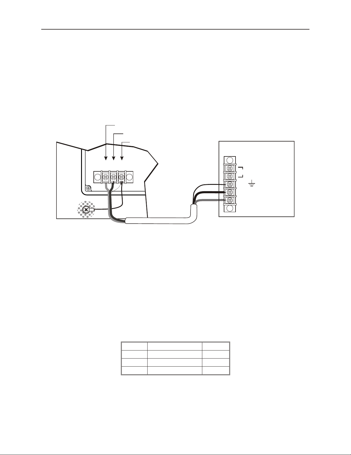
OIT
(rear side)
24Vdc
power supply
Control
panel
Shield wire (bare)
Black wire (-)
Red wire (+)
24V
120Vac
Black
Shield drain
Red
FG
DC Output -V (Gnd)
DC Output +V (+24V)
(+)
GND
(-)
FG
There are two connectors for serial communications on the rear of the OIT. Both of these are D-subminiature 9-pin
connectors.
Use the supplied separate 3-position terminal block to provide power to the OIT.
Con nect the OIT to Power
The power cable for the OIT should be 18AWG, 2-conductor wire with a shield drain wire and protective shield
foil. You may buy cable P/N 6030-0009 by the foot from Maple Systems to make these.
Always run the DC ground wire directly back to the signal return of the power supply. Do not use the chassis
ground wire as your signal return.
4To connect the OIT to power:
1. Connect the power cable to the OIT
a. Strip the power cable shield to expose 2” of the black and red wires.
b. Strip about ¼” of insulation from the black and red wires.
c. Thread the black and red wires through the ferrite core. The shield wire must be outside.
d. Connect the red wire to the DC positive (+) input of the OIT power terminal.
e. Connect the black wire to the DC negative (-) input of the OIT power terminal.
f. Connect the power cable shield wire to the OIT power terminal’s chassis ground input.
2. Route the power cable to the OIT power supply. The power cable should not be any longer
than necessary.
3. Install the power supply wires as follows (with colors shown for Maple Systems cable P/N
6030-0009):
OIT Power Inputs
Color Power Supply OIT
Red +Output/+24 Vdc +24V
Black -Output/+24 Vdc return GND
Shield Case ground FG
1010-1007W, Rev 06
Page 17

12 Sil ver Se ries In stal la tion & Op er a tion Man ual
The power connector on the Silver Series is a terminal block with wire clamps. Lugs
are not required.
Typ i cal Power Wir ing
Panel Prep a ra tion
A metal panel or mounting surface with a minimum thickness of 15 gauge (0.059 inch/3.3mm) if cold-rolled steel or
hardened steel, or 10 gauge (0.101 inch/2.6mm) if aluminum alloy (6061-T6 preferred) is required. Thinner panels
or surfaces may bow between the mounting clamps and not form a seal with the gasket.
The area of the panel or mounting surface where the gasket comes into contact must be flat and free of scratches,
pits, and other features that prevent the gasket from sealing properly. If the panel or mounting surface is not
uniform, thick, flat, stiff, or smooth enough, then a sealant such as silicone may be required.
WARNING: The OIT requires a stiff, flat, smooth mounting surface free of blemishes
to seal properly to NEMA 4.
Clean and deburr the panel cutout before the OIT is installed.
1010-1007W, Rev 06
Page 18
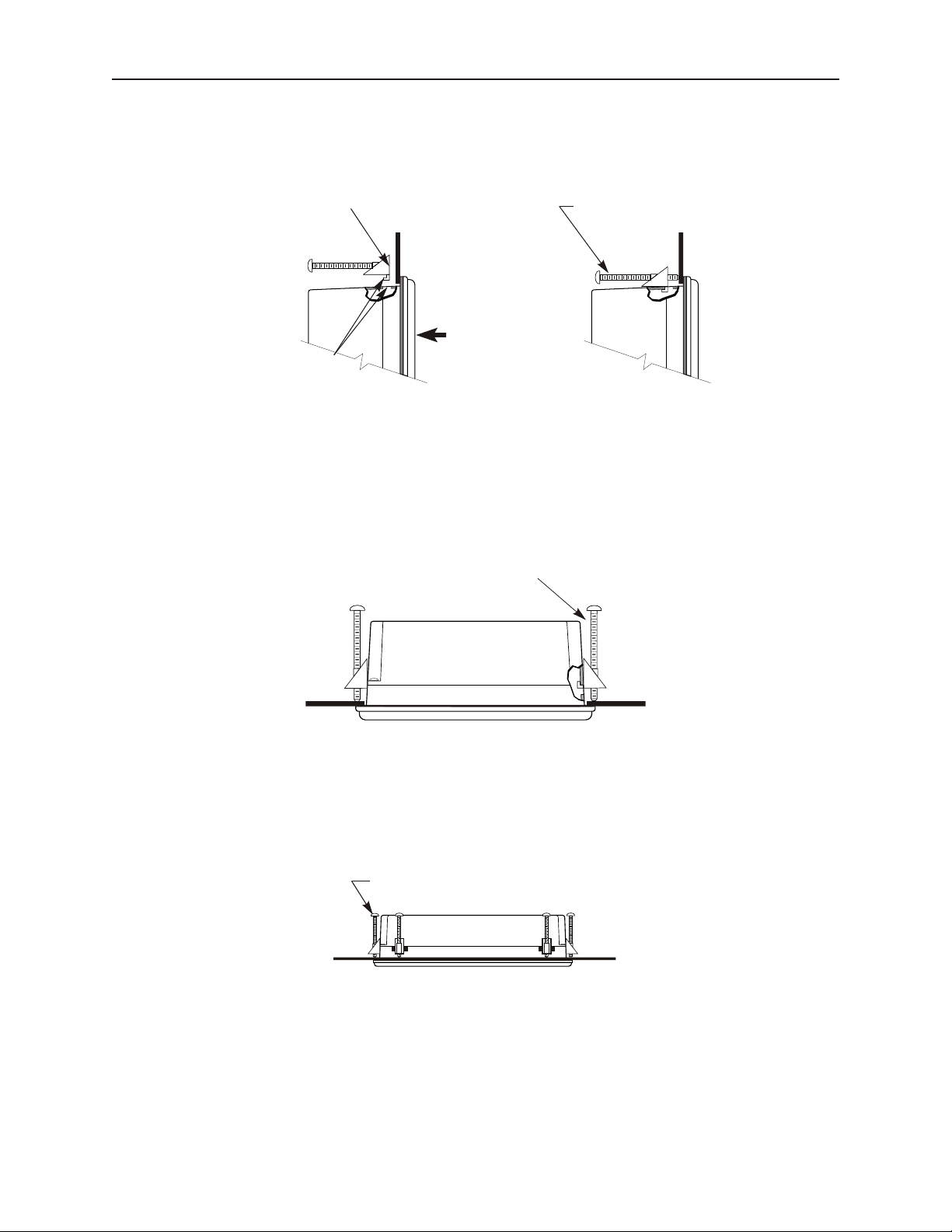
In stal la tion of OITs 13
Position 4 screw clamps
(2 each side)
Panel
Position screw clamps 6 places in slots provided:
2 screw clamps each side and one top and bottom
Panel
Side View
Screw clamp locking
tabs go through the
slots
Tighten all screw clamps until
they are uniformly snug
Ends of screws must not
protrude from the clamp
Screw Clamp Placement Clamps Tightened
Hold the OIT against
the panel until all screw
clamps are in position
PanelPanel
Mount the OIT to the Panel
In stall ing Screws on the OIT
STEPS:
1. Prepare the screw clamps for the OIT by positioning the metal brackets at the midpoints of the screws.
Position the screws so that the ends don’t protrude from the plastic portions.
1010-1007W, Rev 06
Page 19

14 Sil ver Se ries In stal la tion & Op er a tion Man ual
2. Set the OIT in the panel cutout and hold it in place until all clamps are in position.
3. Tighten the screw clamps until all are uniformly snug.
CAUTION: Do not over-tighten the screws beyond snugness, or you may damage the housing, or cause the
touchscreen to malfunction.
REINSTALLATION: Because the gasket will take a “set” to the panel, be sure to reinstall the OIT to the same
panel cutout when a NEMA 4 seal is required. For best results, also replace the gasket itself.
1010-1007W, Rev 06
Page 20

15 Sil ver Se ries In stal la tion & Op er a tion Man ual
Con fig u ra tion Wir ing
The OIT must be configured for a particular protocol before use. The EZware software is used for configuring the
OIT. For detailed instructions on installing and using the software, please refer to the software documentation
section of this manual.
Con nect the OIT to the PC for Con fig u ra tion
To configure the OIT using Maple System’s configuration software, you will need either an Ethernet crossover
cable, Maple P/N 7431-0104 or a USB download cable, Maple P/N 7431-0115 depending upon the OIT model used.
If using a switch or router between the PC and the OIT, use a straight-through or crossover cable as required by the
switch or router.
If an Ethernet port is not available on the PC, you may be able to install a USB
Ethernet adapter. You can also transfer the project to the OIT with a Compact Flash or
USB memory device. Refer to Chapter 2, OIT Local Setup.
1010-1007W, Rev 06
Page 21

16 Sil ver Se ries In stal la tion & Op er a tion Man ual
Please Use This Page For Your Notes:
1010-1007W, Rev 06
Page 22

OIT Lo cal Setup 17
Chapter 2 - OIT Local Setup
Factory Configuration
Each OIT arrives from the factory with a demo project file that illustrates some of the most popular features of the
OIT. Please follow the directions enclosed in Chapter 4, Creating Your First Project, to configure your OIT for the
PLC that you are using.
The OIT also has a black reset push button and a four position DIP switch located through an access hole on the
back of the enclosure. The reset switch can be used to r einitialize the OIT if the OIT malfunctions. Only Dip
switch 1 has functionality. Dip switch 1 puts the OIT into Touch Calibration mode. For normal operation, all of
the DIP switches should be set to the OFF position.
This chapter describes how to use the Silver Series’ local setup options. The local setup allows touchscreen
calibration, transferring projects to and from the OIT, configuring the OIT’s IP settings, passwords, time and date,
screen contrast, as well as managing the storage of recipe and history files. Additionally, memory and other system
information can be viewed.
Calibrating the Touchscreen
The touchscreen of the OIT is fully calibrated before it leaves the factory so you shouldn’t need to adjust it.
However, with time the touchscreen may need to be recalibrated.
4To calibrate the touchscreen:
1. Turn Dip Switch 1 ON.
2. Cycle power to the OIT.
3. After the OIT displays a crosshair cursor, you are prompted to touch the cursor for:
a. Top left position
b. Top right position
c. Bottom right position
d. Bottom left position
e. Center position.
4. The OIT will then resume initializing.
Getting into Local Setup
Accessing the local setup menus requires a USB-mouse be connected to the OIT. Using the mouse, point to the
lower right-hand corner of the OIT. The open bar icon will appear.
Click on the icon to call up the setup toolbar: (note this tool bar is on HMI screen)
System settings
icon
System info icon
Small keyboard
icon
Virtual keyboard
icon
Open/close bar
icon
Large keyboard
icon
Please Note: the above tool bar is located on the HMI.
1010-1007W, Rev 06
Page 23

18 Sil ver Se ries In stal la tion & Op er a tion Man ual
Changing the System Settings
4 To change the system settings on the OIT:
1. Open the Setup Toolbar as described above, and click the System Settings icon.
2. A dialog will be displayed requesting the Local password. The default password is 111111.
You may have to move windows around a bit to gain access to the virtual keyboard.
You may also have to click inside the password field again.
3. Once the correct password has been entered, the System Settings dialog is displayed. For all
tabs, the Cancel, Apply, and OK buttons are available.
Cancel Close the System Settings dialog without saving any changes.
Apply Save the current settings without closing the System Settings dialog.
OK Save the current settings and close the System Settings dialog.
4. Click on the Network tab to configure network settings. The Network dialog is displayed.
5. The Network tab allows configuration of the IP settings. The default setting is Auto Get IP
Address. Use this setting if the OIT will provide an IP address by a DHCP server. If
connected to a DHCP server, this dialog will display the IP settings obtained by the OIT. The
IP fields are disabled, and are not editable.
6. If using a static IP address, use the IP Address Get From Below option. The IP fields are
enabled. Enter the appropriate settings for your network.
1010-1007W, Rev 06
Page 24

OIT Lo cal Setup 19
7. Click the Time/Date tab to configure time/date settings. The time/date dialog is displayed.
8. Configure appropriate time and date settings.
9. Click on the Security tab to display the security settings dialog. Here, you can select your
system passwords.
1010-1007W, Rev 06
Page 25

20 Sil ver Se ries In stal la tion & Op er a tion Man ual
10. Configure your password settings.
Local Password The password required to enter local setup.
Upload Password The password required to upload data from the OIT to a PC or memory module.
Download Password The password required to download data to the OIT from a PC or memory module.
Upload (History)
Password
The password required to upload history from the OIT to a PC or memory module.
11. The new password must be entered, and then entered again to confirm. As the password is
entered into the confirm field, an indicator will show if the two passwords match.
12. Click on the History tab to display the History dialog. This is where data stored in the OIT
can be cleared.
1010-1007W, Rev 06
Page 26

OIT Lo cal Setup 21
This will not clear data stored on a Compact Flash or USB device.
Clear Recipe The OIT’s stored recipe data will be cleared when the Clear button is clicked.
Clear Eventlog The OIT’s stored event log data will be cleared when the Clear button is clicked.
Clear Datalog The OIT’s stored data log data will be cleared when the Clear button is clicked.
13. Click on the Backlight tab to disp lay the Backlight dialog. The Backlight tab adjusts the
brightness of the OIT’s backlight. Use the mouse or touchscreen to roll the wheel. Rolling to
the left decreases the brightness, rolling to the right increases the brightness.
System tags Backlight Up, Backlight Down, and Backlight Index can be used to adjust
the brightness at runtime.
14. Click on the CF Card tab to display the CF card dialog. The CF Card tab displays
1010-1007W, Rev 06
Page 27

22 Sil ver Se ries In stal la tion & Op er a tion Man ual
information about the Compact Flash module. If no CF card is present, the dialog will show
None. Otherwise, volume data about the CF card is displayed.
The Eject button will cause the OIT to ignore the CF device. It will not actually eject the card
from the OIT. If the Eject button is pressed, the CF card must be removed and re-inserted
before the OIT will recognize. Note that USB devices will not be displayed.
Viewing System Information
4 To view system information:
1. Open the Setup Toolbar as described above, and click the System Information icon. A dialog
will be displayed with two tabs.
2. Click on the Network tab to display the current IP settings.
1010-1007W, Rev 06
Page 28

OIT Lo cal Setup 23
3. Click on the Version tab to display the current firmware information.
Transferring Projects and Data from USB/CompactFlash
When a USB or Compact Flash device is inserted into the Silver Series OIT, a dialog is displayed. The same dialog
is displayed for transferring projects or data.
Data is placed on the USB or CF device by EasyBuilder or Project Manager.
Download Project Transfer data from the USB/CF to the OIT
Upload Project Transfer data from the OIT to the USB/CF
Restart Project and exit Close the dialog and restart the OIT
Cancel Close the dialog without transferring
Restart after download/upload When checked, the OIT will restart after the transfer
Time Remaining
The dialog will automatically close after 10 seconds if no selection is
made; shows the time remaining
1010-1007W, Rev 06
Page 29

24 Sil ver Se ries In stal la tion & Op er a tion Man ual
When Download is selected, a dialog will appear requesting the Download password and what data to download.
Password Enter the Download password.
Download Project Files When checked, the OIT will check the specified folder for project data, and transfer it if it exists.
Download History Files
When checked, the OIT will check the specified folder for history data, and transfer it if it exists.
History data includes Recipe , Event Log, and Data Log data.
1010-1007W, Rev 06
Page 30

Con nect the OIT to the PLC or Controller 25
Chapter 3 - Con nect the OIT to the PLC or Controller
The Silver Series family of OITs can connect to one, two or more PLC/controllers. This is accomplished via two
9-pin D-sub serial communications connectors (Port A and Port B) and one Ethernet port. Each PLC/Controller has
its own wiring requirements. Maple Systems offers OIT-to-PLC/Controller communication cables that connect
directly to software controlled COM1, which is available on either Port A or Port B for most PLC/Controllers that
are built to any length and tested for high reliability. The Silver Series family has three software controlled
communications ports located on two physical connectors, designated as Port A and Port B (see Figures 1 & 2,
below).
Fig ure 1 - Com Ports - Rear View
Fig ure 2 - Com Ports - Bot tom View
The three software controlled ports are COM1, COM2, and COM3. Each software controlled communications port
can only be selected for one communication type. Once a communication type is selected for one of these software
controlled ports, that port cannot be used for another communication type. Each of these communication ports has
between one and three communication types. COM1 can be RS232, RS485 4-Wire, or RS485 2-Wire. COM2 is
strictly RS232. COM3 is either RS232 or RS485 2-Wire. COM1 cables are readily available for purchase from
Maple Systems. COM2 and COM3 cables are custom-made according to wiring diagrams that can be found on
Maple Systems' web site. Connecting multiple PLCs and controllers may require a s plitter.
1010-1007W, Rev 06
Page 31

26 Sil ver Se ries In stal la tion & Op er a tion Man ual
COM Ports for the HMI5080/HMI5100/HMI5104/HMI5121/HMI5150
1010-1007W, Rev 06
Page 32

Con nect the OIT to the PLC or Con trol ler 27
COM Ports for the HMI5043/5056/5070
1010-1007W, Rev 06
Page 33

28 Sil ver Se ries In stal la tion & Op er a tion Man ual
5
TX/RX- 1
TX/RX+ 1
GND
1
2
9P
OIT
COM1
RS485
GND5
TX/RX- 1
1
TX/RX+ 12
9S
NOTES:
Shield wire must be terminated to connector metal shell.
1
1
1
WHT/BRN
WHT/GRN
BLU
9
6
COM3
RS485
GND5
TX/RX+ 3
9
TX/RX- 36
9S
1
GRN
BRN
BLU
TX/RX- 3
TX/RX+ 3
Standoff, Hex Extender,
F/F,4-40X0.236,ZP
COM1 RS485 Label
DE9S Connector
& Backshell
1.00”
COM3 RS485 Label
2.00”
DE9P Connector
& Backshell
4-40 x 1/2 Retainer
Screw, 2 places
P/N Label
Approx. 12.00”
Connecting to COM1 and COM3 on Port A
Maple Systems Silver Series family of OITs is capable of connecting to multiple PLC/controllers. If you choose to
take advantage of this feature, and one of your PLC/controllers uses either RS485-4 Wire or RS485-2 Wire
communication, one of four splitters P/N 7431-0111, 7431-0112, 7431-0113, or 7431-0114 will be needed.
Sce nario 1 – One RS232 PLC/Con trol ler, COM1 con fig ured for RS232
When using two RS485-2 Wire PLC/Controllers, with COM1 configured for RS485-2 Wire and COM3 configured
for RS485-2 Wire, splitter P/N 7431-0111 is needed.
1010-1007W, Rev 06
Page 34

Con nect the OIT to the PLC or Con trol ler 29
Standoff, Hex Extender,
F/F,4-40X0.236,ZP
COM1 RS485-4W Label
DE9S Connector
& Backshell
1.00”
COM3 RS485 Label
2.00”
DE9P Connector
& Backshell
4-40 x 1/2 Retainer
Screw, 2 places
P/N Label
Approx. 12.00”
3
RX- 1
RX+ 1
GND
1
2
9P
OIT
COM1
RS485-4W
TX- 13
RX- 1
1
RX+ 1
2
9S
NOTES:
Shield wire must be terminated to connector metal shell.
1
1
1
WHT/BRN
BRN
WHT/GRN
5
4
COM3
RS485
GND5
TX/RX- 3
6
TX/RX+ 39
9S
1
WHT/ORN
ORN
BLU
TX- 1
TX+ 1
9
6
TX/RX- 3
TX/RX+ 3
GRN
BLU
GND
TX+ 1
5
4
Sce nario 2
When using one RS485-4 Wire and one RS485-2 Wire PLC/Controller, with COM1 configured for RS485-4 Wire
and COM3 configured for RS485-2 Wire, splitter P/N 7431-0112 is needed.
1010-1007W, Rev 06
Page 35

30 Sil ver Se ries In stal la tion & Op er a tion Man ual
3
RX- 1
RX+ 1
GND
1
2
9P
OIT
COM1
RS485-4W
TX- 13
RX- 1
1
RX+ 1
2
9S
NOTES:
Shield wire must be terminated to connector metal shell.
1
1
1
WHT/BRN
BRN
WHT/GRN
5
4
COM3
RS232
GND5
TXD 3
7
RXD 38
9S
1
WHT/ORN
ORN
BLU
TX- 1
TX+ 1
8
7
TXD 3
RXD 3
GRN
BLU
GND
TX+ 1
5
4
Standoff, Hex Extender,
F/F,4-40X0.236,ZP
COM1 RS485-4W Label
DE9S Connector
& Backshell
1.00”
COM3 RS232 Label
2.00”
DE9P Connector
& Backshell
4-40 x 1/2 Retainer
Screw, 2 places
P/N Label
Approx. 12.00”
Sce nario 3
When using one RS485-4 Wire and one RS232 PLC/Controller, with COM1 configured for RS485-4 Wire and
COM3 configured for RS232, splitter P/N 7431-0113 is needed.
1010-1007W, Rev 06
Page 36

Con nect the OIT to the PLC or Con trol ler 31
5
TX/RX- 1
TX/RX+ 1
GND
1
2
9P
OIT
COM1
RS485
GND5
TX/RX- 1
1
TX/RX+ 12
9S
NOTES:
Shield wire must be terminated to connector metal shell.
1
1
1
WHT/BRN
WHT/GRN
BLU
8
7
COM3
RS232
GND5
RXD 3
8
TXD 37
9S
1
GRN
BRN
BLU
TXD 3
RXD 3
Standoff, Hex Extender,
F/F,4-40X0.236,ZP
COM1 RS485 Label
DE9S Connector
& Backshell
1.00”
COM3 RS232 Label
2.00”
DE9P Connector
& Backshell
4-40 x 1/2 Retainer
Screw, 2 places
P/N Label
Approx. 12.00”
Sce nario 4
When using one RS485-2 Wire and one RS232 PLC/Controller, with COM1 configured for RS485-2 Wire and
COM3 configured for RS232, splitter P/N 7431-0114 is needed.
1010-1007W, Rev 06
Page 37

32 Sil ver Se ries In stal la tion & Op er a tion Man ual
5
RXD1
TXD1
GND
2
3
9S
OIT
COM1
RS232
GND5
RXD1
2
TXD13
9P
NOTES:
Shield wire must be terminated to connector metal shell.
1
1
1
WHT/BRN
WHT/GRN
BLU
6
4
COM2
RS232
GND5
RXD2
6
TXD24
9P
1
GRN
BRN
BLU
TXD2
RXD2
Standoff, Hex Extender,
F/F,4-40X0.236,ZP
COM1 RS232 Label
DE9P Connector
& Backshell
1.00”
COM2 RS232 Label
2.00”
DE9S Connector
& Backshell
4-40 x 1/2 Retainer
Screw, 2 places
P/N Label
Approx. 12.00”
Connecting to COM1 and COM2 on Port B
If both controllers use RS232 communication then only one splitter, P/N 7431-0110 is needed.
1010-1007W, Rev 06
Page 38

Con nect the OIT to the PLC or Con trol ler 33
RS-485
Silver Plus Series OIT
PLC
PLC
PLC
PLC
Connecting multiple PLC/controllers serially using daisy chaini ng
The RS485 4-wire and RS485 2-wire communications ports of the Silver Series family supports multi-drop
connections. A daisy-chain connection is made from the OIT to the first PLC/controller, and then from the first
PLC/controller to the second and so on (see below). The network may need biasing resistors – refer to the
PLC/controller documentation for more information.
Refer to the Help Section of EasyBuilder-5000, under the How do I Section… for more
information.
Connecting one or more PLC/controllers via Ethernet
The Silver Series OITs have a single RJ45 Ethernet connector, configured for 10BaseT and 100BaseT operation.
This port is for both communicating with a PC for configuration purposes, as well as for communicating with
supported Ethernet PLCs and protocols.
The connector is wired just like the RJ45 Ethernet connector on a PC. The Ethernet connection to a PLC/controller
will vary with each PLC/controller. Some will require a straight-through connection, while others require a
crossover connection. See Maple Systems' website for cable drawings of Ethernet cables.
4To connect a single PLC/controller to an OIT:
1. Attach one end of the Ethernet cable to the RJ45 connector on the OIT
2. Attach the other end to the RJ45 connector on the PLC/controller
A router or switch is required to connect multiple PLCs/controllers to a single OIT. In general, standard
straight-through type cables can be used when connecting to a PLC/controller through a router or switch. Some
routers and switches may be auto-sensing. In this case, either type of cable may be used.
1010-1007W, Rev 06
Page 39

34 Sil ver Se ries In stal la tion & Op er a tion Man ual
Please Use This Page For Your Notes
1010-1007W, Rev 06
Page 40

Cre ating Your First Project 35
Chapter 4 - Creating Your First Project
Often the best way to learn about new software is to jump right in. This chapter will step you through the process of
installing the EZware-5000 configuration software and then using the software to create a sample project that can be
downloaded to your OIT. We won’t go into much detail about how each feature works. The purpose of this
chapter is only to provide you with an overview of the process of creating a functional OIT that can communicate to
a PLC. For our sample project, we will configure the OIT using the local OIT Memory, but you may feel free to
select whichever protocol driver you intend to use.
By the end of this chapter, you should be able to:
• Install EZware-5000 configuration software.
• Create a sample project with two windows and several graphics objects.
• Save a project, compile a project and download the project to the OIT.
• Verify that the OIT is functioning properly.
Be fore You Be gin
Before you install EZware-5000, make sure your computer meets the following minimum system requirements:
• Pentium-based 1.7 GHz or higher processor
• 512 MB of RAM (more memory improves performance)
• 200 MB available hard disk space
• VGA or higher-resolution monitor set for 16 Bit color 1024 x 768 pixel mode
• Microsoft mouse or compatible pointing device
• One available Ethernet port
• Microsoft Windows XP, 2000 or Vista
Con nect ing OIT to Com puter
Before you start your first project, the OIT should be connected to the computer so that the project can be
downloaded after creating it. You should also connect the PLC that you are using to the OIT so that you can test the
operation of the OIT after you have finished creating this sample project.
4To connect your OIT to the computer
1. Connect a +24VDC power supply to the OIT.
2. Connect a crossover Ethernet cable between the OIT and PC.
3. Apply power to the OIT.
Starting EZware-5000
Before you can create a sample project, you must start the configuration software. The EZware-5000 software has
two main applications:
• EasyBuilder – used to create the project downloaded to the OIT.
• Project Manager - used to place the OIT into different operating modes.
4To start the EZware-5000
1. From the Windows Task Bar, click the Start button, point to Programs, and then click the
Maple Systems-EZware-5000-Project Manager.
2. On the Project Manager dialog box, click EasyBuilder5000.
3. The Welcome to EasyBuilder dialog box appears. Select the correct OIT model.
4. Click OK to display the System Parameters screen of EasyBuilder.
1010-1007W, Rev 06
Page 41

36 Sil ver Se ries In stal la tion & Op er a tion Man ual
The following illustration shows the various sections of EasyBuilder.
Manager toolbar
Part1toolbar
Work area
Part2 toolbar
Draw Toolbar
Cre at ing a Sam ple Pro ject
This section walks you through the creation of an EasyBuilder project named MTPrj1. Once downloaded to the
OIT, this basic configuration allows the OIT to connect to the PLC, display a startup screen, and display a screen
containing one PLC register monitor when a switch on the startup screen is pressed.
Although we strongly recommend that you perform the following steps to create this sample project, the project is
already included in your EasyBuilder software with the following filenames:
HMI5056.MTP-sample project for the HMI5056
HMI5070.MTP-sample project for the HMI5070
HMI5080.MTP-sample project for the HMI5080
HMI5104.MTP-sample project for the HMI5104
HMI5121.MTP-sample project for the HMI5121
HMI5150.MTP-sample project for the HMI5150
Set ting the Sys tem Pa ram e ters
Whenever you begin a new project, you should always set the system parameters before you create any windows.
System parameters determine the basic operating conditions of the OIT such as what type of PLC it is connecting to.
4To edit the System Parameters
1. Click the Edit menu on the main screen of EasyBuilder.
1010-1007W, Rev 06
Page 42

Cre ating Your First Project 37
2. At the bottom of the menu, click System Parameters. The System Parameters dialog box
appears.
3. The dialog box has six tabs: Device, Model, General, Security, Font and Extend Memory.
Select the Device tab.
4. Click New… The Printer Server Dialog appears.
1010-1007W, Rev 06
Page 43

38 Sil ver Se ries In stal la tion & Op er a tion Man ual
5. Select your controller from the drop down menu next to PLC Type: Click Settings... The
Com Port Settings dialog appears.
6. Set Com Port Settings that match your PLC. Reserved settings are specific to each type of
PLC. Refer to the Controller I nformation Sheet for that PLC for more details. Click OK
twice to return to System Parameter Settings dialog
1010-1007W, Rev 06
Page 44

Cre ating Your First Project 39
7. Now click on the General tab.
8. In the Option section, for the Startup Window no: drop-down, select 10. WINDOW_010
9. Click OK to return to the EasyBuilder main screen.
For more information, consult your PLC operations manual or Maple Systems
Controller Information Sheets available on our website at www.maple-systems.com .
Creating a Popup Window
We will first configure Window #11 as a popup window. We will be using a function key in the startup window to
call this popup window; however, this window must first exist before we can map the function key to it, which is
why we are creating the popup prior to creating the startup window.
Multiple popup windows can be displayed on a full screen window. The windows may overlap each other or be
moved anywhere onscreen. This section will show how to create a scale and a numeric register that displays the
current value of the scale. You will also create an increment and decrement key to change the value in the scale
meter.
1010-1007W, Rev 06
Page 45

40 Sil ver Se ries In stal la tion & Op er a tion Man ual
4To create Window#11
1. From the Window menu, click Open Window. The Open Window dialog box appears.
2. Click New… The Select Window Style dialog box appears.
1010-1007W, Rev 06
Page 46

Cre ating Your First Project 41
3. Click Base Window. The Window Setting dialog box appears:
4. Type WINDOW_011 in the Name: field and 11 in the Window no: field.
5. In the Size section, enter 210 for the width. Enter 150 for the height.
6. Click the pull down box from the Background Color box. The Color dialog box appears.
7. Click on the white color box, then click OK. The color box will reflect the color that you
have chosen.
8. In the Popup window section, enter 60 for the X position. Enter 60 for the Y position.
9. Click OK. The Open Window dialog will reappear.
10. In the Open Window dialog , highlight Window 11, then click on the Open button. Window
11 now appears on your work area, configured to the size indicated above.
1010-1007W, Rev 06
Page 47

42 Sil ver Se ries In stal la tion & Op er a tion Man ual
4To create a meter display on Window#11
1. From the Objects menu, click Meter Display. The New Meter Display Object dialog box
appears.
2. Type Meter Display in the Description box.
3. Click the Outline tab to configure the meter style.
1010-1007W, Rev 06
Page 48

Cre ating Your First Project 43
4. In the Start Degree, type 270
5. In the End Degree box, type 90.
6. Uncheck "Full Circle".
7. Check Enable in the tick marks section.
8. Select black as the tick marks color.
9. Select main scale 6, sub. scale 1, length 6 for tick marks.
10. Select pointer arm style and length.
11. Click on the Limits tab.
12. Set value 0, Span 100.
13. Enable range limits and select low, mid and high colors. Width = 3.
14. Click OK.
15. Click the work area to place the meter.
16. On the main screen of EasyBuilder, you will see a white square outline that is attached to your
cursor in the work area. This represents the meter display just created. Click to place the
meter display in Window #11.
17. Now, resize the meter so that it is a better fit on the popup window. Double click on the
meter display to re-display the attribute dialog.
18. Click the Profile tab to display the profile form.
19. Enter the following values:
X: 45
Y: 13
Width: 120
Width: 120
20. Click OK.
4To create a numeric register on Window#11
1. From the Objects menu, click Numeric/ASCII - Numeric Display. The New Numeric
Display dialog box appears.
2. Type Numeric Data in the Description box.
3. Click OK.
4. On the main screen of EasyBuilder, you will see a white rectangle outline that is attached to
your cursor in the work area. This represents the numeric register just created. Click to place
1010-1007W, Rev 06
Page 49

44 Sil ver Se ries In stal la tion & Op er a tion Man ual
the numeric register on Window #11 somewhere underneath the scale meter. A numeric
register box will appear.
4To create an increment key on Window#11
1. From the Objects menu, click Button-Set Word. The New Set Word Object dialog box
appears.
1010-1007W, Rev 06
2. Type Increment Button in the Description box.
3. Click on the pull down box of the Mode: box and select Press and hold increment (JOG++)
4. Enter 1 in the Inc. value box.
5. Enter 100 in the Upper limit box.
6. Click on the pull down box of JOG Delay and select 0.5 second.
Page 50

Cre ating Your First Project 45
7. Click the Shape tab.
1010-1007W, Rev 06
Page 51

46 Sil ver Se ries In stal la tion & Op er a tion Man ual
8. Check Use shape, then click Shape library. The Shape Library dialog box appears.
9. Click Select Lib… The Open dialog box appears.
10. Select arrow1.plb from the list of shape libraries. Then click Open.
11. Click arrow1 in the Shape library box.
12. Scroll through the selections to selection 3. Click the shape, then click OK. The shape will
appear in the Shape tab.
13. Click OK.
14. On the main screen of EasyBuilder, you will see a white square outline that is attached to your
cursor in the work area. This represents the increment key just created. Click to place the
increment key on Window #11.
15. Use the blue handles surrounding the key to drag the increment key to the desired size and
then place to the left of and below the numeric object.
4To create a decrement key on Window#11
1. We are going to create the decrement key by copying the increment key and then making
changes to the attributes.
2. Click the increment key to highlight it.
3. From the Edit menu, click Copy.
1010-1007W, Rev 06
Page 52

Cre ating Your First Project 47
4. From the Edit menu, click Paste. A copy of the increment key appears in the upper left
corner of the work area. Deselect the increment key by clicking on any blank space in the
work area.
5. Double-click on the second increment key. The Set Word Object’s Attribute dialog box
appears.
6. In the General tab section, change the Description to Decrement Button.
7. Click on the pull down box of the Mode Attribute: and select Press and hold decrement
(JOG—).
8. Enter 0 in the Attribute Bottom limit box.
9. Click the Shape tab.
10. Click Shape library. The Shape Library dialog box appears.
11. Scroll through the selections to selection 4. Click the shape, then click OK. The shape
should appear in the Shape tab.
12. Click OK.
1010-1007W, Rev 06
Page 53

48 Sil ver Se ries In stal la tion & Op er a tion Man ual
13. Drag the decrement button to the bottom right area of your window.
4To create a close window button
1. Finally, we must create a button that will close the popup window. From the Objects menu,
click Function Key. The New Function Key Object dialog box appears.
2. Type Close Window in the Description box.
3. Click the Close Window radio button.
4. Click the Shape tab to display the shape dialog.
5. Unclick the Use shape checkbox and click the Use picture checkbox. Click the Picture
library button. The Picture Library dialog box appears.
6. Click the Select Lib. Button on the bottom of this dialog box. Select the computer.flb
library, then click Open.
7. Under the Library: list box, you will now see computer. Click on computer to display this
library.
8. Scroll through the selections to selection 21. Click the picture , then click OK. The color box
will reflect what you have chosen.
9. Now click the Label tab and make sure Use Label checkbox is not checked. Click OK.
10. On the main screen of EasyBuilder, you will see a white square outline that is attached to your
cursor in the work area. This represents the function key just created. Move this key to the
upper right corner of the screen and click to place.
11. Now double-click on this key to redisplay the attribute box. Click on the Profile tab.
12. Enter X:170 and Y:7 for position values. Enter Width: 33 and Height: 28 for the size
values.
13. Click OK.
Cre ating a Startup Win dow
We will now configure Window #10 as the startup screen. The OIT can store up to 1999 predefined windows but
screens 0-9 are reserved. Therefore, the first window screen that is available for configuration is Window #10. By
default, this is the startup screen when you begin a new project. This section will show how to place text in the
window and how to create two function keys that will open and close Window #11.
1010-1007W, Rev 06
Page 54

Cre ating Your First Project 49
To Display Window #10, from the Window menu, click 1 MTP1-Window10. Window 10 will now appear in your
workspace.
4To place text on Window#10
1. From the Draw menu, click Text. The New Text Object dialog box appears.
1010-1007W, Rev 06
Page 55

50 Sil ver Se ries In stal la tion & Op er a tion Man ual
2. Click the pull down box from the Color box. The Color palette appears.
3. Click on the white color box, then click OK. The color box will reflect the color that you
have chosen.
4. Select 16 in the size box.
5. Select Left in the Align box.
6. Double-click the word ‘text’ in the Content box and type “This is the Startup Screen.”
7. Click OK.
8. On the main screen of EasyBuilder, you will see a white rectangle outline that is attached to
your cursor in the work area. This represents the text box just created. Center the rectangle
somewhere on the top third portion of the work area and then click. The text box “This is the
Startup Screen” will appear.
1010-1007W, Rev 06
Page 56

Cre ating Your First Project 51
4To create a function key on Window#10
1. From the Objects menu, click Button-Function Key. The New Function Key Object dialog box appears.
2. Type On Button in the Description box.
3. Click Display Popup Window.
4. Type 11 in the Window No. Box.
1010-1007W, Rev 06
Page 57

52 Sil ver Se ries In stal la tion & Op er a tion Man ual
5. Click the Shape tab to display the shape dialog..
1010-1007W, Rev 06
Page 58

Cre ating Your First Project 53
6. Check the Use shape checkbox, and then click Shape library. The Shape Library dialog
box appears.
7. Click button1 in the Shape library box.
8. Scroll through the selections to selection 23. Click the shape, then click OK. The shape will
appear in the Shape tab.
1010-1007W, Rev 06
Page 59

54 Sil ver Se ries In stal la tion & Op er a tion Man ual
9. Click the Label tab. The label dialog appears.
1010-1007W, Rev 06
10. Check the Use Label checkbox.
11. Click the pull down box from the Color box. The Color dialog box appears.
12. Click on the black color box, then click OK. The color box will reflect what you have
chosen.
13. Select 16 in the Size box.
14. Select Left in the Align box.
15. Type ON in the Content box..
16. Click OK.
17. On the main screen of EasyBuilder, you will see a white square outline that is attached to your
cursor in the work area. This represents the function key just created. Center the square
somewhere on the bottom left portion of the work area and then click. The function key will
appear.
18. Double-click on the function key. The Function Key Object’s Properties box appears.
Page 60

Cre ating Your First Project 55
19. Click on the Profile tab.
20. Enter 47 for the X position. Enter 168 for the Y position.
21. Enter 62 for the Width. Enter 49 for the Height.
22. Click OK.
23. On the main screen of EasyBuilder, you will see the function key that you just created move
and/or change size. This function key is used to display Window #11.
4To create a second function key on Window#10
1. We could create the second function key by repeating the steps for the first function key.
Instead, however, we will take advantage of the first function key and copy it.
2. Click the first function key to highlight it.
3. From the Edit menu, click Copy.
4. From the Edit menu, click Paste. A copy of the function key appears in the upper left corner
of the work area. Deselect the function key by clicking on any blank space in the work area.
5. Double-click on the second function key. The Function Key’s Object Attribute dialog box
appears.
6. In the General tab section, change the Description to Off Button.
7. Click on Close Window. Enter 10 for Window number
8. Click on the Label tab. Type OFF in the Content box.
9. Click on the Profile tab.
10. Enter 196 for the X position. Enter 168 for the Y position.
11. Click OK.
12. On the main screen of EasyBuilder, you will see the second function key that you just created
move to the lower right hand side of the work area. This function key is used to close
Window #11.
You have finished configuring your first window. It will look similar to the picture below:
You have now done your part in creating this sample project. It is now time for EZware -5000 to do its part.
Fin ishing Up
There are still a few steps, which must be completed before you can test your first project. In this section, you will:
• save the project onto your computer hard drive
• compile the project into a format that can be understood by the OIT
• download the project to the OIT
• verify that the OIT operates as expected
• exit the EZware-5000 software
1010-1007W, Rev 06
Page 61

56 Sil ver Se ries In stal la tion & Op er a tion Man ual
If you haven’t already done so, now would be a good time to connect the OIT to the
computer and to connect the PLC that you are using to the OIT For more information,
consult the first part of this chapter or see “Installation of OITs” later on in this
manual.
4Saving your first project
1. From the File menu, click Save As. The Save As dialog box appears.
2. Use the drop-down menus to locate the project folder.
3. In the File name text box, type MTPrj1.
4. Click Save. The file is saved onto your computer hard drive and the main screen of
EasyBuilder reappears.
4Compiling your first project
1. From the Tools menu, click Compile. The Compiling dialog box appears.
1010-1007W, Rev 06
Page 62

Cre ating Your First Project 57
2. Click Compile. EasyBuilder will compile your project and display error results.
3. If no errors occur, click Close. The main screen of EasyBuilder reappears. If errors have
occurred, repeat the steps in the Creating a Sample Project section.
4Downloading your first project
It is necessary to determine the IP Address of the OIT. By default, the OIT is configured to get a dynamic IP
address from a DHCP server. This setting can be changed, To determine or change the OIT’s IP address:
1. Plug a USB mouse into the OIT.
2. Apply power to the OIT.
3. Move the mouse pointer to the lower right corner of the OIT screen. A menu bar will appear,
Click the wrench icon on the left side of the bar.
4. On the Network tab of the System Settings dialog, the OIT’s IP address will be shown. If set
for Auto Get IP Address, the OIT’s current IP setup information is displayed but is not
changeable. To change the IP address, select IP Address Get From Below and enter the data.
5. Once the IP Address has been established, the project can be downloaded. From
EasyBuilder’s Tools menu, select Download. Or, click the Download icon.
6. Enter the OIT’s IP address and Download password. The default download password is
111111. The default address is 192.168.0.201, Subnet 255....0, Gateway 192.168.0.254.
7. Make sure that the Firmware and Reboot HMI After Download boxes are checked.
8. Click the Download button. If the OIT is properly connected to the PC, the status box on the
download dialog will update with messages indicating the progress of the transfer. The OIT
itself will also display messages reflecting its status.
9. When the download is complete, the OIT will restart. Click the Exit button on the Download
dialog.
CONGRATULATIONS. You have completed your first EZware-5000 project.
1010-1007W, Rev 06
Page 63

58 Sil ver Se ries In stal la tion & Op er a tion Man ual
Please Use This Page For Your Notes:
1010-1007W, Rev 06
Page 64

Sim u la tor Mode 59
Chapter 5 - Simulator Mode
As you saw from creating the sample project in the last chapter, downloading any changes you make to the OIT can
take time. To decrease the amount of time required to download a project to the OIT , uncheck the Firmware option
on EasyBuilder's download dialog.
A better way of testing changes made to a project is to use the computer to simulate the operation of the OIT.
This chapter shows you how to dramatically save time when creating and testing a project by putting the computer
into Simulation Mode. In Simulation Mode, the computer displays a screen that simulates what is seen when the
OIT executes the project file. You can use the mouse on your computer to simulate the operation of the touchscreen
on the OIT. Rather than waiting for the download to test each change you make to your project, you can now
instantly switch to Simulation Mode to see if your project is working as expected.
You can enter Simulation Mode in three ways. Using the sample project that you created in the last chapter, we will
guide you through the three methods.
The Sim u la tion Screen
All modes of simulation use the same screen.
For our example, we are showing the sample project as it would appear after the ON function key has been pressed.
When the Simulation Mode screen first appears, it will always show the startup screen of the project. You can test
any objects you have created which require touchscreen input by clicking on them. In this example, clicking on the
increment key simulates the key as it is pressed on the touchscreen. Simulation Mode always uses the compiled
version of the project that you have created (the *.xob file). Therefore, you must save and compile any changes you
make to the project before you can simulate it.
Simulating the OIT is done in on-line or off-line mode.
On-line simulation is most useful when a project is near completion and you need to test the interaction of the
project with the PLC. It is also very convenient when making minor changes to a project because these changes can
be instantly checked for operation.
Off-line simulation does not require any connection to the OIT. Because of this, off-line simulation is most often
used when starting a project. You can quickly test new ideas and create preliminary screens without the OIT.
Off-line simulation is also great for demonstrating the operation of the OIT and becoming familiar with the
operation of the OIT before it is installed. If you want to simulate the interaction with a PLC when off-line, it can be
done by creating additional windows on the OIT which allow PLC data input.
4To use off-line simulation mode from EasyBuilder:
1. If the project has been modified since the last time it was saved and compiled, or if it has not
yet been compiled, it must be saved and compiled before the simulator can start.
1010-1007W, Rev 06
Page 65

60 Sil ver Se ries In stal la tion & Op er a tion Man ual
2. From the Tools menu, click Off-line Simulation or click the Off-line Simulation icon in the
Standard toolbar.
3. The Simulation Mode screen will appear.
4. To end off-line simulation, right click in the simulation screen and click Exit.
4To use on-line simulation mode from EasyBuilder
1. If the project has been modified since the last time it was saved and compiled, or if it has not
yet been compiled, it must be saved and compiled before the simulator can start.
2. From the Tools menu, click On-line Simulation or click the On-Line Simulation icon in the
Standard toolbar.
3. The Simulation Mode screen will appear.
4. To end on-line simulation, right click in the simulation screen and click Exit.
Simulation mode can also be started from Project Manager. Project Manager requires only the compiled project file
(*.xob). This can be useful in situations in which you want to demonstrate changes made to a project for a client
without giving him access to your project file. It also allows you to rapidly switch from simulating one project to
another without having to open, save, and compile each project.
4To use off-line simulation mode from Project Manager
1. Start the Project Manager software.
2. Click Offline-Simulator. The Open Project box appears.
3. Click on the compiled project file that you wish to simulate.
4. Click Open. The simulation screen will appear.
5. To end off-line simulation, right click in the simulation screen and click Exit.
4To use on-line simulation mode from Project Manager
1. Start the Project Manager software.
2. Click the Online-Simulator. The Open Project dialog box appears.
3. Click on the compiled project file that you wish to simulate.
4. Click Open. The simulation screen appears.
5. To end on-line simulation, right click in the simulation screen and click Exit.
Online simulation requires a direct connection between the PC and the controller. It is not necessary to have the
OIT connected.
The OIT’s COM1 RS232 connection is wired the same as a standard PC 9-pin serial connector. Therefore, the
standard Maple Systems’ COM1 RS232 cable for the selected PLC/controller can be used with online simulation.
Connect the cable end marked "HMI" to the PC’s serial port, and connect the other end to the PLC/controller.
The above method will work with a standard PC serial COM port, regardless of the
COM number assigned to the PC serial port. EasyBuilder supports RS232
communication on ports COM1-COM9. COM3 and higher are intended for use with
online simulation, since the OIT itself supports RS232 communication on COM1 and
COM2 only.
If simulating with RS422 or RS485 communication, the PC will require some
mechanism to support RS422/485. A communication card can be installed in the PC, a
USB communications module can be used, or an external RS232/RS485 converter can
be used. In any case, a standard Maple Systems cable may not work.
If simulating a project using Ethernet communications, an Ethernet cable between the PC and the PLC/controller is
needed. Consult the PLC/controller documentation for details.
Now that you are familiar with using simulation mode, the next chapter guides you through the fundamental
operation of three primary segments of the EZware-5000 configuration software.
1010-1007W, Rev 06
Page 66

Using EZware-5000 61
Chapter 6 - Using EZware-5000
Over view
The EZware-5000 software is composed of three separate applications which are accessible from the EZware-5000
folder: EasyBuilder, Project Manager, and EasyConverter. EasyBuilder is the application software used to create a
project file. Project Manager is a utility application that puts the OIT into different op erating modes.
EasyConverter changes certain binary files created by the OIT into text files.
By the end of this chapter, you should be quite familiar with the operation of Project Manager and be able to
maneuver around EasyBuilder easily. This will pave the way for actually creating graphics objects in later chapters.
EasyBuilder 5000 includes extensive online help. From any dialog box within the
software, click on the HELP button, or press the computer's F1 key.
The Pro ject Manager
The Project Manager utility sets the communications parameters that are used by the computer when communicating
to the OIT. The utility can also be used to:
• Start EasyBuilder
• Write project data to a CompactFlash or USB device for transfer to an OIT
• Download project data to the OIT or upload project data from the OIT
• Start a project simulation session.
To access Project Manager, click on the Windows Start button and select All Programs-Maple
Systems-EZware-5000-Project Manager.
1010-1007W, Rev 06
Page 67

62 Sil ver Se ries In stal la tion & Op er a tion Man ual
The following illustration shows the various commands available:
Com mu ni ca tions & Password Settings
Set tings But ton
1. Download/ Upload passwords (default 111111)
1010-1007W, Rev 06
Page 68

Using EZware-5000 63
Re boot HMI
Connects to the OIT, checks password and resets the OIT in order to update system files.
Editor Settings
EasyBuilder-5000
Brings up EasyBuilder-5000 editing software for project creation and editing.
Build Down load Data for CF/USB Disk
Data can be downloaded to the Silver Series OITs using both CompactFlash and USB jump drives. The Build
Download Data function builds the data to do this.
To build download data for CompactFlash or USB jump drive:
1. Insert CF card or USB jump drive to OIT.
2. Start Project Manager.
3. Click Build Download Data for CF/USB Disk… The Project Manager dialog appears.
4. Insert CF card or USB jump drive into PC. Note the folder that represents the USB/CF
device.
5. Click Browse... to select the folder that represents the USB/CF device.
6. Check the boxes that will be the sources for your data and browse to the appropriate file for
that source.
7. Click Build.
Easy Converter Application
The EasyConverter application is used to view data log files (*.dtl) and event log files (*.evt) that are created by the
OIT during operation. Data log files are files the OIT creates when capturing data using the Data Sampling object.
Event log files are history files the OIT creates when using the Event Log object. Both files are in binary format to
minimize the amount of file space required.
To view these files with a computer, you must use the EasyConverter application. In addition, EasyConverter can
take a data or event log file and convert it into a CSV (Comma Separated Value) file that can be easily imported into
other applications such as Microsoft Excel. For more information on how to do data logging, see Chapter 12 “Bar
1010-1007W, Rev 06
Page 69

64 Sil ver Se ries In stal la tion & Op er a tion Man ual
Graphs, Meters, and Trends”, section “Creating Trend Displays & Data Sampling Objects”. For more information
on how to use Event Log files, see Chapter 13 “Capturing Alarms and Events”, section “Monitoring Alarms with the
Alarm/Event Log”.
To start the EasyConverter Application
1. From the Tools menu, click Data/Event Log Converter. Or click the Data/Event Log Converter icon in the
Project toolbar. You can also access the EasyConverter application from the Project Manager. The EasyConverter
application appears:
2. Click File…Open to display the Open dialog box. Search for the data log file (*.dtl) or event log file (*.evt) that
you wish to view, then click the Open button.
Please Note:
These files are captured by the OIT and stored in internal OIT memory, an attached SD card or USB flash drive.
You must copy these files into your computer before using the EasyConverter utility. If you are running a project
that is capturing data log or event log files using the Offline Simulator, the EZware-5000 application automatically
creates new folders on your computer and creates the files.
Data log files are stored in a folder using the name that you assigned in the Data Sampling Object attribute box
(ex:C:\MapleSystems\EZ5000\datalog\History Data1\20090618.dtl).
Event log files are stored in an eventlog folder (ex: C:\MapleSystems\EZ5000\eventlog\EL_20090625.evt).
Viewing an Event Log File (*.evt) using EasyConverter Application
1. From the EasyConverter application, click File…Open and locate the Event Log file (*.evt):
1010-1007W, Rev 06
Page 70

Using EZware-5000 65
2. [Creation time]: the text line below the creation time heading shows the date and time that the file was initially
created. Format is Day of Week, Month, Day of Month, Time (24Hr format), and Year.
3. [Data fields]: the text line below this header is used to label and identify each column of data under the [Data]
header. The Data fields header shows the event number, category of event, time event occurred in 24HR format,
and the event (alarm) message recorded.
4. [Data]: this is where the actual data is recorded. Note that this is read only- the EasyConverter application does
not allow any edits.
Viewing a Data Log File (*.dtl) using EasyConverter Application
1. From the EasyConverter application, click File…Open and locate the Data Log file (*.dtl). As the file is loaded,
the following popup window appears:
2. Display Milliseconds: This option determines how the time value for each data record is displayed. In this
window you have four options:
1010-1007W, Rev 06
Page 71

66 Sil ver Se ries In stal la tion & Op er a tion Man ual
3. Decimal display and Scaling option: The dialog box below allows you to select different formats for the data
before it is displayed:
4. For this example, we have elected to use the linear scaling formula on Data 0 to convert the raw data (which is
measuring temperature in °F) to °C.
Also, the raw data collected for Data 4 is a floating point number calculated to three decimal places. However, we
are only concerned with a two decimal accuracy, so we change the ‘Digits’ field from 3 to 2. If we want to use
these same changes on other files, click the Save Setting… button to save the changes as a conversion (*.lgs) file.
When opening other data log files, we can apply the same changes by clicking on the Load Setting button and
selecting the proper conversion file.
Click OK to continue.
5. The data log file is shown:
In our example, notice that the value for Data 0 {200°F} has changed to 93°C and the value for Data 4 has two
decimal places {1697.85} instead of three {1697.850}.
1010-1007W, Rev 06
Page 72

Using EZware-5000 67
6. [Creation time]: the text line below the creation time heading shows the date and time that the file was initially
created. Format is Day of Week, Month, Day of Month, Time in 24Hr format and Year.
7. [Data]: the text line below this header is used to label and identify each column of data recorded. The header
shows the time each record was captured followed by the title given for each data column.
Please Note: this is read only-- the EasyConverter application does not allow any edits.
1010-1007W, Rev 06
Page 73

68 Sil ver Se ries In stal la tion & Op er a tion Man ual
Converting a Data /Event Log File to a CSV file using EasyConverter Application
After opening a Data/Event Log file into EasyConverter, you can easily export the file into a CSV file. Note:
Microsoft Excel is required to convert the file.
1. Click File…Export to Excel or click on the Excel icon
2. Microsoft Excel is activated and you should see the data in a spreadsheet. Simply click File…Save As to save the
file.
3. Converting multiple files: EasyConverter also has a feature that allows you to select multiple Data/Event Log files
and save them to one CSV file. To do this click File…Multi-File or click on the Multi-File icon.
4. Click Add File…, then select which Data/Event Log files you wish to combine.
5. Enable Setting file: check this box to select a conversion (*.lgs) file that performs a linear scaling conversion or
decimal point conversion on the selected files.
6. Combine to a file: check this box to combine the files and put them into an Excel spreadsheet.
1010-1007W, Rev 02
Page 74

69
Please Use This Page For Your Notes:
1010-1007W, Rev 06
Page 75

Us ing EZware-5000 70
Easy Printer
The Easy Printer button allows monitoring of the print server through Project Manager. The EasyPrinter utility must
be running on the PC that is hosting the networked printer from which you wish the Silver Series OIT to print.
1010-1007W, Rev 06
Page 76

71 Sil ver Se ries In stal la tion & Op er a tion Man ual
Recipe/Extended Memory Editor
The Recipe/Extended Memory Editor is an application that allows you to create, view, and modify recipe (*.rcp)
files and Extended Memory (*.emi) files. You can also use this editor to import/export recipe and extended memory
files to CSV formatted files which can then be shared by other applications.
To create a new Recipe/Extended Memory file:
From the Project Manager application, click Recipe/Extended Memory Editor:
1. Click File . . . New. The following dialog box appears:
2. Address range (unit:word) frame -- use this frame to select the total number of RW (recipe word) registers or
EMx (Extended Memory) registers that are used for the recipe or extended memory file. In the example above,
RW0 thru RW100 will be used.
3. Data format frame- use this area to enter how each data register element is be interpreted by the OIT. The data
collected and stored in recipe/extended memory files is in binary format and does not contain any information about
how each data should be interpreted by the OIT (for example, is the data in 16-bit signed integer format or BCD?).
Therefore, the data format is used to define how each data element is formatted (ie. Signed vs Unsigned, 16-bit vs
32-bit, Float, String, etc.).
1010-1007W, Rev 06
Page 77

Using EZware-5000 72
a. Add: Click to add a new data register format. The following dialog box appears:
In the Data Type Dialog Box you can enter a description of the Data Type or Preset Value.You can also select
which format that the OIT will use to interpret the data.
Please Note: For String format, you must enter the total number of 16-bit register words used for the character
string.
b. Delete: If you wish to delete an item from the list, highlight a data element and click delete to remove from list.
c. Clear All: click to erase entire list of data elements.
d. Modify: highlight a data element and click Modify to revise the name of the data element or format.
e. Below is an example of a list of data elements created:
1010-1007W, Rev 06
Page 78

Using EZware-5000 73
4. Select your data format frame- use to select or create a data format template that can be used for other recipes or
extended memory files. In the example above, the data elements configured in the ‘Data format’ frame have been
saved to a template called ‘Recipe1’. Click OK.
5. A table of data elements appears that shows the recipe or extended memory table:
This table has several columns with headers:
a. ID: this is the ID number for each record.
b. Address: this is the starting RW address or EMx address for each record.
c. Data headers: these are the descriptions used for each data element created in the step above.
6. Edit the table by clicking on each data element field and entering the preset value. Please note that you are only
allowed to enter data according to the format defined for each data element.
Here is an example of a completed table:
1010-1007W, Rev 06
Page 79

74 Sil ver Se ries In stal la tion & Op er a tion Man ual
7. Click File...Save with the following options:
a. Save file as *.rcp for recipes.
b. Save file as *.emi for extended memory files. Note: You must use file names which correspond to the ten
extended memory areas preconfigured in the OIT (ex. em0.emi, em1.emi, …, em9.emi).
c Save file as *.csv to import file into applications such as Microsoft Excel.
8. Once the file is saved, you can copy the recipe file to your OIT by:
a. Procedure 1-- Downloading the file using the Project Manager:
i. With the computer connected to your OIT, click Transfer…Download.
ii. On the Download dialog box, check the RW enable box, then select the recipe file.
b. Procedure 2 -- Downloading using a SD card or USB Flash Drive:
i. Attach an SD card or USB Flash Drive to your computer.
ii. In Project Manager, click Build Download Data fo r CF/USB Disk button:
iii. Select the folder to save download data: Enter the SD card or USB Flash drive location.
iv. Check the Recipe (RW) enable box, then select the recipe file.
v. Click the Build button. A folder called ‘mt8000’ is created on the root directory of your drive.
vi. Remove the SD or USB drive and connect it to your OIT.
Please Note: if you are using more than one USB device, make sure that the USB Flash drive is connected first (this
identifies the USB Flash Drive as USB1).
1010-1007W, Rev 06
Page 80

Using EZware-5000 75
Transfer Settings
Download
Sends a compiled project file stored on the computer to the OIT.
Up load
Receives a compiled project file from the OIT to be stored on the computer.
For more information about printing, see the Systems Configuration Settings/Printer tab section later in this chapter.
Simulation Settings
On-line Sim u la tion
Opens a compiled project (*.xob) in on-line simulator mode.
Off-line Simulation
Opens a compiled project (*.xob) in off-line simulator mode.
1010-1007W, Rev 06
Page 81

76 Sil ver Se ries In stal la tion & Op er a tion Man ual
Pass-through mode
The pass-through mode allows serial communications from the PC to the PLC, though the OIT. This can eliminate
the need to disconnect the PLC from the OIT when it is necessary to configure the OIT.
To use the pass-through mode:
1. HMI/IP: Specify the IP Address of the OIT that is to be used in passthrough mode or click
Get HMI Communication Parameters to read the current communication settings for the
OIT.
2. HMI work mode: Indicates the current mode of the OIT. After the communication
parameters have been received, the mode will be either Normal (OIT set to communicate with
PLC) or Passthrough (OIT is in pass-through mode).
3. Source COM Port: Set Com settings for the OIT that will be connected to the PC.
4. Destination COM Port: Set COM settings for the OIT that will be connected to the PLC.
5. Click Start Pass-through to begin passthrough and Stop Pass-through to end. Click Exit to
exit pass-through mode.
That’s all there is to Project Manager.
The EasyBuilder Ap pli ca tion
This section guides you in how to operate the EasyBuilder application; however, it does not show you how to
program your OIT or how to create graphics objects. These topics are reserved for later chapters. This section
shows the fundamental operation of EasyBuilder from saving files, printing projects, and selecting the target PLC to
showing how graphics objects can be easily manipulated in the EasyBuilder work area. When you have completed
this chapter, you will be better able to use the features that are explained in later ch apters.
1010-1007W, Rev 06
Page 82

Using EZware-5000 77
The following illustration is used for reference to the following sections:
1010-1007W, Rev 06
Page 83

78 Sil ver Se ries In stal la tion & Op er a tion Man ual
Man ag ing Pro jects
Like most Windows™ application software, EasyBuilder will open, save, close, and print files using the standard
windows format.
Open ing, Editing Pro jects
To create a new project
1. On the File Menu, click New or click the New icon in the Standard toolbar. The EasyBuilder
dialog box appears.
2. Select the OIT model you intend to use with your project.
A project’s display mode may be changed after the initial selection has been made. To
set Display Mode select Edit-System Parameters…, and select the Model tab. To
change the Display Mode, resize the window’s resolution to fit the mode selected.
1010-1007W, Rev 06
Page 84

Using EZware-5000 79
3. Click OK. The System Parameter Settings dialog appears.
1010-1007W, Rev 06
Page 85

80 Sil ver Se ries In stal la tion & Op er a tion Man ual
4. This is where you will select your PLC or controller. Click New… to bring up the Device
Properties dialog.
5. Select the PLC option button and then select the PLC type from the drop down menu.
Configure any necessary COM ports and click Settings... to bring up the COM Port Settings
dialog.
1010-1007W, Rev 06
Page 86

Using EZware-5000 81
6. Configure the appropriate COM port settings for your PLC (for more information, see the
Controller Information Sheet for your PLC) and click OK.
7. Adjust Interval of Block pack settings, if necessary. This can be adjusted later by selecting
System Parameters-Settings.
8. Click OK. You are now ready to begin working in EZware-5000 to create your EasyBuilder
project.
4To open an existing project
1. On the File Menu, click Open or click the Open icon in the Standard toolbar. The Open
dialog box appears.
2. Click on the project file you intend to open.
3. Click Open. The main screen of EasyBuilder appears with the initial screen of the project
displayed.
4To close a project
1. On the File Menu, click Close.
2. If changes have been made to the project file, EasyBuilder will ask you if you would like to
save the project. Then the main screen of EasyBuilder will remain but with no work area
displayed. You must now use the Open or New commands to edit a project.
4To save an existing project
1. On the File Menu, click Save or click the Save icon in the Standard toolbar.
2. If the project already has a name, then the project will automatically be saved. If this is a new
project, then the Save As dialog box appears.
3. Enter a file name and then click Save.
4. The main screen of EasyBuilder reappears.
4To save a project using the compress feature
The compress feature allows you to save a project in compressed format so that the pr oject data takes less space on
your hard drive. This utility also will save the graphics lib raries associated with the project into the project file.
This facilitates sending a copy of the project to another person who has EZware in order to download the project
into an OIT.
1010-1007W, Rev 06
Page 87

82 Sil ver Se ries In stal la tion & Op er a tion Man ual
1. From the Tools menu, select Compress/Uncompress.... The Compressing dialog box
appears.
2. In the Compress frame box under Source Name, select the project (*.mtp) file that you wish
to compress. File must have a .mtp extension.
3. Click Compress… to begin. The utility will compress the project file and all related graphics
libraries into a single file.
4To extract a compressed project file
1. From the Tools menu, select Compress/Uncompress.... The Compressing dialog box
appears.
2. In the Uncompress frame box under Source Name, select the project (*.cmp) file that you
wish to uncompress.
3. Click Uncompress… to begin. The utility will extract the project file and all graphics
libraries from the *.cmp file.
4To exit EasyBuilder
On the File Menu, click Exit -- or click on the standard windows Close icon in the upper right corner.
Editing and Cre ating Screen Ob jects
This section shows how to manipulate graphics objects that are placed onto the work area of EasyBuilder. We will
use examples from sample projects that are included with the EasyBuilder software: HMI5043.MTP,
HMI5057.MTP, HMI5070.MTP, HMI5080.MTP, HMI5100.MTP, HMI5104.MTP, HMI5121.MTP and
HMI5150.MTP. Please load one of these project files and have EasyBuilder ready before you begin this section.
We will refer to Window_12 of the project. To display Window_12 on EasyBuilder, perform the following steps.
4To open a window
1. On the Window Menu, click Open Window. The Open Window dialog box appears.
2. Click Window_12..
1010-1007W, Rev 06
Page 88

Using EZware-5000 83
3. Click Open. Window_12 appears in the work area of EasyBuilder.
Dis play Options
Before we begin describing some of the commands that can be used to edit graphics objects, there are a few
commands that apply to the general work area of EasyBuilder.
EasyBuilder provides a Window Tree that can be used to easily maneuver between windows of a project. It also
allows you to select any object that is on the window that is currently displayed.
4To display/hide the Window Tree
1. On the View Menu, click Window Tree
4Using the Window Tree to display window screens
1. The Window Tree combines into a single tree a list of all of the windows in a project, and all
of the objects on each window. Using the 5056DEMO.MPT project, the following should be
seen :
2. Notice that the tree displays the title for each window next to the window number. This
makes it easy to determine windows have been created for a project. The asterisk (*) next to
Window #10 indicates that this window is currently open.
3. To display an open window, click on the window number in the Window Tree. To display a
window that is not yet open, double-click on the window number. This will automatically
open the window and display it.
1010-1007W, Rev 06
Page 89

84 Sil ver Se ries In stal la tion & Op er a tion Man ual
4. To change any settings or close an open window, click on the window number to select it.
Then right-click anywhere inside the Window Treebar to display a pop-up dialog box. Select
Close to close the window or Setting to change any of the window settings.
5. Finally, to create a new window click on any window number that is not currently used.
Then, right-click inside the Window Tree and click New.
4Using the Window Tree to change object attributes
1. On the Window Tree, click + adjacent to any window number. The tree will expand to list
the objects on that window, as shown:
2. The Object ID of each objects will be listed. For example, TX_0 is Text Display #0, SW_0 is
Set Word #0, etc.
3. To highlight a particular object on the screen, click on the Object ID in the list. This allows
the quick selection of a particular object, especially on crowded screens or screens where
objects may be overlapping..
4. To display the object’s attribute dialog box, double-click the Object ID in the Window Tree.
4Using the grid function
One option is to have the work area covered with grid lines. These grid markings can be helpful when trying to
align objects that are created on the work area. If grid lines are selected, you can decide what size each grid is.
1. On the Option Menu, click Grid/Snap.
2. Click the Display box or click the Grid icon in the Standard toolbar.
If you still don’t see the grid after you have enabled it, make sure that the color of the
grid doesn’t match the background color of the window currently displayed.
4Changing the grid size & color
1. On the Option Menu, click Grid/Snap
2. Select the X spacing and Y spacing for grid size.
1010-1007W, Rev 06
Spacing is measured in pixels.
3. Select the Grid color in the drop down menu.
Page 90

Using EZware-5000 85
Another option is to display what are known as Object ID tags. Every time you create a new object in EasyBuilder,
an Object ID tag is assigned to the new object. This is done for several reasons:
• Object ID tags are required by EasyBuilder to differentiate each ob ject created.
• If an error occurs during the compil e process, EasyBuilder can refer to the w indow and object ID to
indicate the object that is causing problems.
4To enable/disable Object ID tags
1. On the Option Menu, click Function Property. The Function Property dialog box appears.
2. Click the Display Object ID checkbox to display tags.
3. Click OK.
If you enable the Grid on the work area, you may also take advantage of a useful feature called Snap. The Snap
option causes all objects placed into the work area to fall along the boundaries set by the grid lines. The Snap
option can help provide a more ordered appearance to graphics objects.
4To use the snap option
1. The Grid option must be enabled.
2. On the Option Menu, click Grid/Snap. The Grid/Snap Settings dialog box appears.
3. Click the Snap checkbox.
4. Click OK.
Finally, you will find that you can move objects by selecting them with the mouse cursor and dragging them to a
new location. However, you may find it difficult to select an object without accidentally moving it just a little. At
times this may be frustrating, so you may wish to disable the move feature using the mouse and only move an object
by changing it’s X and Y position parameters in the Profile tab of the object’s attributes box. This is the intent of
the Fix Objects feature.
4To enable the fix objects command
1. On the Option Menu, click Grid/Snap. The Grid/Snap Settings dialog box appears.
2. Click the Fix Objects checkbox.
3. Click OK. Movement by mouse cursor is now disabled.
4To zoom in on the selected window
1. Use the zoom pull-down menu at the top right of the screen. Zoom levels range from 50% to
200% in 25% increments.
1010-1007W, Rev 06
Page 91

86 Sil ver Se ries In stal la tion & Op er a tion Man ual
4To change the state of the selected window
1. Use the zoom pull-down menu at the top right of the screen.
2. The objects will appear as they would in the selected state.
Ba sic Ed it ing Com mands
4To select a graphics object
1. On the Edit Menu, click Select or click the mouse cursor icon in the Draw toolbar.
2. Click on the graphics object. For example, using Window_12, click on Fill Level. This
causes the text box to be selected, with small square blocks around the edges indicating the
boundaries of the object. Deselect the object by clicking somewhere else in the work area.
3. When a graphics object is selected, it can then be modified, copied, deleted, or moved to a
new location.
4To select multiple graphics objects
1. On the Edit Menu, click Select or click the mouse cursor icon in the Draw toolbar.
2. Click and hold down the left mouse button at the upper left corner of the graphics objects you
wish to highlight. For example, using Window_12, click to the left and above of Motor
Speed.
3. Move the mouse cursor to the lower right corner of the highlighted objects. Notice that a
rectangle is formed as you do this. In this example, move the mouse to the right and below
Fill Level.
4. Release the mouse button. The rectangle outline changes to small clear square blocks around
the perimeter of the objects selected. Now both objects are selected.
If you do not completely enclose any graphics objects you wish to highlight, then they
will not be selected.
5. Alternatively, you may select objects by holding down the CTRL key while selecting each
object until all objects are selected.
6. When several graphics objects are selected, they can easily be moved, deleted or copied
together.
4To select next object
1. This option can be used to easily select an object that is underneath another object on the
screen. To use this option, you must first select the overlapping object.
2. On the Edit Menu, click Select Next Object or click on the Select Next Object icon on the
Standard toolbar. You can also right-click on the top-most object on the screen. This will
display a menu with a list of the overlapping objects on the bottom. Then check the object
that you wish to access.
1010-1007W, Rev 06
Page 92

Using EZware-5000 87
3. Once the object you are trying to access is selected, you can proceed to modify its attributes
or delete it.
4To select all objects
1. On the Edit Menu, click Select All Objects.
2. Small, clear, square blocks appear around the perimeter of all the objects on the window.
3. You can now easily move, delete or copy the entire window screen to a new window.
4Using the Undo and Redo commands
1. The Undo command is used to cancel the last command or action that you made. For
example, select the Motor Speed text box in Window_12.
2. Press the DELETE key on your keyboard to delete the text box.
3. From the Edit menu, click Undo or click the Undo icon from the Standard toolbar. You can
also press CTRL+Z. The deleted text box reappears.
4. The Redo command is used to cancel the Undo command. For example, if you decided that
you really did want the Motor Speed text box deleted, click the Redo command.
4Using the Cut , Copy , and Paste commands
1. These commands are all selected from the Edit menu or by clicking the appropriate icon in
the Standard toolbar.
2. Select the graphics object or objects you wish to cut or copy.
3. Click Cut to copy and remove the graphics object(s) from the work area or click Copy to
copy the graphics object(s). Using Window_12, select the Motor Speed text box and then
press CTRL+X to cut the object from the work area.
4. Objects cut or copied from one window can be pasted into other windows. Once the object
has been selected and cut or copied, open another window, then paste the object into that
window.
5. In this example, paste the Motor Speed text box back into Window_12 by pressing CTRL+V.
The pasted object appears highlighted in the upper leftmost corner of the work area.
6. Move the text box by clicking on the highlighted object and dragging it back to the original
position.
4Using the Multi-Copy command
The Multi-Copy command is used to make multiple copies of a single object on a screen. This is most useful when
creating new keyboards or data tables. In addition to copying the object, this command will automatically assign
new PLC memory addresses to each object, (applies only to Bit-type objects).
1. Select the object you wish to copy.
1010-1007W, Rev 06
Page 93

88 Sil ver Se ries In stal la tion & Op er a tion Man ual
2. From the Edit menu, select Multi. Copy.... The Multi. Copy dialog box appears.
3. Modify the settings according to your requirements.
4. Click OK. The main screen of EasyBuilder is redisplayed with the Multi. Copy command
executed.
Multiple objects can be created according to these parameters:
· Pitch vs. Interval: This setting affects how EasyBuilder places the copies of an object on the screen relative
to each other. The Pitch setting will interpret the X Distance setting as the distance from the left side of an
object to the left side of the next object and the Y Distance setting as the distance from the top of one object
to the top of another object.
The Interval setting will interpret the X Distance setting as the distance from the right side of one object to
the left side of the next object. The Y Distance setting is the distance from the bottom of one object to the
top of the next object.
· X Distance, Y Distance: These settings determine the spacing (in pixels) between objects.
· Quantity X, Quantity Y: These settings determine the number of copies to be made along the X axis
(horizontal) and the Y axis (vertical).
· Adjust Distance: This is the offset used when assigning a new PLC memory coil address to each new
copy. For example, if 1 is selected, then EasyBuilder will add one to the PLC memory coil address for each
new copy made.
4Using the Window Copy command
The Window Copy command is used to copy a window from an existing project into the project that you are
currently editing. This feature reduces time spent creating new projects since you can now use windows that you
created for other similar projects.
1010-1007W, Rev 06
Page 94

Using EZware-5000 89
1. From the Edit menu, select Window Copy.... The Window Copy dialog box appears.
2. In the Source Project: box, specify the path to the project that contains the window screen
you wish to copy. Use the Browse... command button if you are unsure of the location or
name of the project file.
3. In the Source Window box, enter the number of the window screen you wish to copy.
4. In the Destination Window box, enter the number of the window screen in the project you
are currently editing that you wish to copy the contents of the source window to.
5. Click OK. The main screen of EasyBuilder is redisplayed with the Window Copy command
executed.
4To delete a graphics object(s)
1. Select the object or objects you wish to delete.
2. Press the DELETE key or from the Edit menu, click Delete.
You can restore the deleted object by using the Undo command.
4To move a graphics object(s)
1. Select the object or objects you wish to move.
2. When you place the mouse cursor over a highlighted object, the cursor changes to a crosshair.
This indicates that you are able to move the selected object. Move the object by clicking on it
and dragging the object to the proper position on the work area.
4To resize a graphics object
1. Select the object to be resized.
2. To resize the object, move the mouse cursor over one of the small black squares. The cursor
changes to a double-arrow icon to indicate that it is in resizing mode.
3. Click and drag the mouse to resize the object.
4. Objects can also be resized by changing the width and height attributes in the Profile tab of
the Attributes dialog box, (see below).
4To change attributes of a graphics object
1. Select the object to be changed, then select Change Attribute from the Edit menu. You can
also double-click the object.
2. The object’s attribute dialog box is displayed. Object Attributes defines what the object is or
how it behaves, (i.e. size, position, color, etc.). Click OK to accept any changes made or
Cancel to cancel any changes.
4To view object attributes of multiple graphics objects on a window
1. There will be times when you may want to quickly determine what PLC data registers are tied
to which objects in a window. This can easily be done using the object attributes command.
1010-1007W, Rev 06
Page 95

90 Sil ver Se ries In stal la tion & Op er a tion Man ual
2. For this example, open Window_11 to display the popup window of the sample project.
3. On the Edit menu, click Select all objects.
4. From the Edit menu, click Change Attribute. The Object Attribute dialog box is displayed.
5. All of the objects that use PLC data registers or the internal memory of the OIT are listed in
this dialog box according to their Object ID tag. Alongside each ID tag is the PLC or OIT
memory identifier.
Group ing Ob jects
When creating graphics on a window, you may create a complex graphic that is actually composed of several
simpler objects overlaid onto each other. This numeric display with increment and decrement button is an example
of grouped objects.
This numeric display is actually composed of three separate objects:
a numeric display an increment button a decrement button
1010-1007W, Rev 06
Page 96

Using EZware-5000 91
These objects are then overlaid to represent the scale. Grouping the three objects together makes it easier to move
or copy the scale meter. Instead of copying each separate object, the scale meter can be assigned as a group, then
copied as though it were one object.
4To group objects
1. Select the objects to be grouped.
2. From the Edit menu, click Group or click the Group icon from the Manager toolbar.
3. All objects within the group can now be copied, deleted, or moved by clicking on the group.
4To ungroup objects
1. Select the objects to be ungrouped.
2. From the Edit menu, click UnGroup or click the UnGroup icon from the Manager toolbar.
3. All objects within the group can now be copied, deleted, or moved separately.
Layering Ob jects
Graphics objects can be overlaid upon each other. When ‘layered’ the graphics object on the topmost layer will be
completely seen. How much of the other graphics objects are seen depends on what is on top of them. The
following layer commands help to position the overlaid objects exactly how you want them. To better illustrate how
layering works we will use a rectangle object, a circle object and an arc object that are overlaid on each other in
Window_12 of the sample project.
4Using the top and bottom layer commands
1. Select one of the layered objects. In this example, select the layered rectangle from
Window_12.
1010-1007W, Rev 06
Page 97

92 Sil ver Se ries In stal la tion & Op er a tion Man ual
2. From the Edit menu, click Layer, then TopLayer or click the TopLayer icon from the
Manager toolbar. Note that the rectangle completely overlaps the circle and the arc.
3. From the Edit menu, click Layer, then BottomLayer or click the BottomLayer icon from
the Manager toolbar. Note that the rectangle recedes behind the circle an d the arc.
4Using the next and previous layer commands
1. These two commands can move an object through the various layers of other objects.
2. Select one of the layered objects. Again, select the layered rectangle from Window_12.
3. From the Edit menu, click Layer, then PreviousLayer or click the PreviousLayer icon from
the Manager toolbar. Note that the rectangle covers the circle but no t the arc.
4. From the Edit menu, click Layer, then NextLayer or click the NextLayer icon from the
Manager toolbar. Note that the rectangle recedes behind the circle and the arc.
Normally, an object that is controlled by a PLC Register (i.e., a Word Lamp, Bit Lamp, Animation, etc.) is brought
to the Top Layer when the value in the PLC Register changes. This behavior can be changed by the Object Layout
1010-1007W, Rev 06
Page 98

Using EZware-5000 93
option on the General tab of the System Parameters dialog. A setting of Control sets the behavior as outlined above.
A setting of Nature (default setting) will result in the object remaining at the layer assigned during development.
The Object Layout setting is global - affects all PLC-controlled objects in the application.
Nudg ing Ob jects
Nudging is used to fine-tune the movement of objects in the work area of EasyBuilder. Using the nudge feature on
a selected object will move that object in the specified direction either by one pixel or by the grid setting amount.
4Using the nudge top , bottom , left , and right commands
1. Select one of the layered objects or a group of objects in the work area of EasyBuilder.
2. From the Edit menu, click Nudge, then select the direction of the nudge or click the
appropriate icon from the Manager toolbar.
Aligning Ob jects
Alignment can be used to quickly align two or more objects. Aligning justifies objects to the desired position of the
last-selected object. The last select object will have "handles" of a different color than the other selected objects. To
better illustrate, refer to the left side of Window_12 of the sample project:
4Using the align left command
1. Select the objects you wish to align. For this example, select the three rectangle objects of
Window_12.
1010-1007W, Rev 06
Page 99

94 Sil ver Se ries In stal la tion & Op er a tion Man ual
2. From the Edit menu, click Align, then Left or click the appropriate icon from the Manager
toolbar.
3. From the Edit menu, click Undo to put the objects back in their original position.
4Using the align right command
1. Select the objects you wish to align. For this example, select the three rectangle objects of
Window_12
2. From the Edit menu, click Align, then Right or click the appropriate icon from the Manager
toolbar.
3. From the Edit menu, click Undo to put the objects back in their original position.
4Using the align top command
1. Select the objects you wish to align. For this example, select the three rectangle objects of
Window_12.
1010-1007W, Rev 06
Page 100

Using EZware-5000 95
2. From the Edit menu, click Align, then Top or click the appropriate icon from the Manager
toolbar.
3. From the Edit menu, click Undo to put the objects back in their original position.
4Using the align bottom command
1. Select the objects you wish to align. For this example, select the three rectangle objects of
Window_12
2. From the Edit menu, click Align, then Bottom or click the appropriate icon from the Manager
toolbar.
3. From the Edit menu, click Undo to put the objects back in their original position.
4Using the align horizontal center command
1. Select the objects you wish to align. For this example, select the three rectangle objects of
Window_12.
1010-1007W, Rev 06
 Loading...