

Page 1

Page 2

COPYRIGHT NOTICE
This manual is a publication of Maple Systems, Inc., and is provided for use by its customers only. The contents of the
manual are copyrighted by Maple Systems, Inc.; reproduction in whole or in part, for use other than in support of Maple
Systems equipment, is prohibited without the specific written permission of Maple Systems.
WARRANTY
Maple Systems warrants each product to be free from electrical and mechanical defects in materials and workmanship for a
period of two years from the date of shipment. This warranty does not apply to defects in the Products caused by abuse,
misuse, accident, casualty, alteration, negligence, repair not authorized by Maple Systems, use on current or voltages other
than specified by Maple Systems, or application or installation not in accordance with published instruction manuals. This
warranty is in lieu of any other warranty either expressed or implied.
Maple Systems’ liability is limited to the repair or replacement of the Product only, and not costs of installation, removal, or
damage to user’s property or other liabilities. If Maple Systems is unable to repair or replace a nonconforming Product, it
may offer a refund of the amount paid to Maple Systems for such Product in full satisfaction of its warranty obligation.
Maximum liability of Maple Systems is the cost of the Product.
Information furnished by Maple Systems, Inc., is believed to be accurate and reliable. However, no responsibility is assumed
by Maple Systems for the use of this information nor for any infringements of patents or other rights of third parties which
may result from its use. No license is granted by implication, or otherwise, under any patent or patent rights of Maple
Systems, Inc. Maple Systems retains the right to revise or change its products and documentation at any time without notice.
IF SERVICE IS REQUIRED
Package the unit in its original packaging container or, if unavailable, any suitable rigid container. If a substitute container is
used, surround the unit with shock absorbing material; damage in shipment is not covered by the warranty. Include a letter
with the unit describing the difficulty and designating a contact person. Send to the following address: Maple Systems, Inc.,
808 134
th
Street SW, Suite 120, Everett, WA 98204-7333.
Only Products that have been issued a Return Material Authorization (RMA) number from Maple Systems may be returned.
All RMAs must be accompanied with a written purchase order for tracking purposes or, in the case of out-of-warranty
repairs, for repair charges on a time and material basis.
All returns will be tested to verify customer claims of noncompliance with the product warranty. Improper return packaging,
which makes verification impossible, will void the warranty. Products passing the tests will be returned “AS IS” to the
customer.
If noncompliance is verified and is not due to customer abuse or the other exceptions described with product warranty, Maple
Systems will, at its option, repair or replace the Product returned to it, freight prepaid, which fail to comply with the
foregoing warranty, provided Maple Systems is notified of such noncompliance within the two-year warranty period.
APPLICATIONS ASSISTANCE
This manual is designed to provide the necessary information for trouble-free installation and operation of your new Operator
Interface Terminal (OIT). However, if you need assistance, please call Maple Systems at 425-745-3229 or visit our web site
at www.maple-systems.com.
Page 3

Table of Contents
Introduction - Welcome ..................1
BlueLeaf Support ..................1
OIT Models Supported ...........1
PLCs Supported ................1
About Your Documentation ..........1
Conventions......................1
What You Need ...................2
OIT Basics .......................3
What is a Blue Series OIT? ........4
List of Features.................5
Chapter 1 - Installation of OITs ............7
Before You Begin .....................7
Unpacking the Unit ................7
Managing Electrostatic Discharge. . . 7
CE Compliance ................7
NEMA Rating ..................7
Environmental Considerations .....7
Safety Precautions ..............8
Control Panel Design Guidelines ......9
Control Panel Grounding .........9
Connect OIT Chassis Ground to Control
Panel ........................9
Power Supply Selection ..........10
Connect the OIT to the PLC .......12
Panel Preparation ..............13
Mount the OIT to the Panel .......14
Configuration Wiring ...............14
Connect the OIT to the PC for Configura-
tion .........................14
Factory Configuration...............16
Chapter 2 - Creating Your First Project ......17
Before You Begin ..................17
Connecting OIT to Computer ......17
Starting BlueLeaf ..................18
Creating a Sample Project ...........19
Selecting the PLC ...............20
Creating Two Screens............20
Creating a Startup Screen ........20
Creating a Second Screen ........23
Finishing Up......................26
Chapter 3 - Using BlueLeaf Software ........29
Overview ........................29
The BlueLeaf Application ............29
Managing Projects ..............30
System Screens ................31
Editing and Creating Screen Objects 32
Basic Editing Commands ............34
Chapter 4 - Basic Operation of the BLU300 . . . 47
Overview ........................47
Using the Left, Right, Top and Down Keys48
Local Setup Menus .................48
Accessing the Local Setup Menus . . . 48
Downloading a Project to the
BLU300 ......................49
Uploading a Project from the BLU30049
Transferring a Project Between Two
BLU300s .....................50
HMI Setup Menu for the BLU300 . . . 51
HMI Configuration Settings .......57
Chapter 5- Creating and Displaying Screens . . 63
Creating Screens ..................63
Opening a Screen ..............63
Creating a New Screen ..........66
Deleting a Screen...............67
Creating a Herald Screen............67
Configuring the Herald Screen .....67
Writing the Screen Number to a PLC
Register .........................68
How to Display Screens .............69
Jump to Screen Feature ..........69
Displaying screens using function
keys .........................71
Displaying screens using the up/down
arrow keys ....................71
Displaying Screens Using the System
Parameter Setting .................71
Chapter 6 - Creating Graphics Objects ......73
Drawing Objects ..................73
Using the Drawing Tools .........73
Using Text ....................79
Predefined Bitmaps ................81
Using a Predefined Bitmap ........81
Creating Custom Bitmaps.........82
Chapter 7 - Using Dynamic Objects .........83
Representing PLC Coil Registers .......83
The Bit Lamp Object.............83
The Word Lamp Object ..........84
The Multi-State Bitmap w/Label
Object .......................87
The Clock Display Object .........89
The Dynamic Messages Object .....92
Chapter 8 - Entering/Displaying Numeric and
ASCII Characters .......................95
Representing PLC Data Registers ......95
The Numeric/ASCII Display Object . . 95
The Numeric Input Object ........97
Displaying and Using the Numeric Entry
Screen ..........................100
Chapter 9 - Using The Function Keys ........105
The Button Object .................105
Using the Button Object ..........105
The Function Key Editors ............107
Using the Global Function Key Editor 107
Using the Local Function Key Editor . 109
Chapter 10 - Bar Graphs, Meters, Trends and XY
Plots .................................113
Creating Bar Graphs ...............113
Page 4

ii Blue Series Installation & Operation Manual
Creating Analog Meters .............115
Creating Trend Displays .............117
Creating XY Plots ............119
Chapter 11 - Using Alarms ...............123
Using Alarms .....................123
Monitoring Alarms with the Alarm
LED Editor .................123
Monitoring Alarms with the Alarm Buzzer
Editor.....................125
Displaying Alarms using the Dynamic
Message Object .............127
Chapter 12 - Using a Memory Stick .........133
Copying a project from the BLU300 to the
PCC............................133
Copying a project from the PCC to the
BLU300 .........................134
Appendix A - Specifications ...............137
BLU300M: .......................137
Display ...................137
Hardware .................137
Mechanical ................137
Environment................137
Certifications ...............137
Power Requirements..........137
Communications ............138
Memory Stick Support ........138
Keypad ...................138
Available Keys ..............138
Screens ...................138
Graphics Libraries ...........138
Text ......................138
Bar Graphs ................139
Meters ....................139
PLC Register Control .........139
Alarms ....................139
Additional Features ..........139
Appendix B - Dimensional Outlines & Panel
Cutout ...............................141
1010-0300, Rev 02
Page 5

Introduction 1
Introduction - Welcome
Welcome to the Maple Systems’ BLU300 Series of Operator Interface Terminals (OITs). The BLU300 is a low cost,
easy-to-use graphical operator interface with membrane-style keypad. The BLU300 connects to programmable logic
controllers (PLCs) to provide the human-machine interface in industrial applications. The BLU300 Series has several
features not found in other low cost OITs. This manual explains the operation of the BLU300 Series OITs and how to
implement the many available features using the BlueLeaf Configuration Software.
BlueLeaf Support
OIT Models Supported
The BlueLeaf configuration software supports the BLU300 operator interface terminal which is a 128x64 pixel backlit LCD
display with five function keys and control keys. It is specifically designed for applications in which a small yet robust user
interface is required.
PLCs Supported
For the latest list of PLCs and controllers supported by the BLU300Series OITs, please visit our website.
About Your Documentation
Maple Systems provides many resources to allow you to get the most out of your BLU300 Series OIT.
• BLU300 Series Operation Manual (shipped with BlueLeaf software as a PDF file) - describes installation,
general operation and features of the BLU300 Series and how to configure it using the BlueLeaf
configuration software.
• Controller Information Sheets - important information specific to each supported protocol.
• BlueLeaf On-line Help - covers the operation of the BlueLeaf software. Always available by clicking
Contents from the Help menu in BlueLeaf.
For more information about these and other training sources, visit the Maple Systems web site at:
http://www.maple-systems.com
Conventions
When using BlueLeaf software, there are usually several ways to perform a task. For example, if you want to copy a graphics
object, you can:
•
Click the Copy command on the Edit menu.
•
Click the Copy button on the Standard toolbar.
•
Press the CTRL + C keys on your computer.
In most cases, we will describe each method when the task is first discussed. The menu method is then used whenever the
task is used in later procedures. Other conventions used in this book are listed in the following table.
1010-0300, Rev 02
Page 6

2 Blue Series Installation & Operation Manual
Convention Meaning
Bold
Italic
ALL
CAPITALS
KEY1+KEY2
click Refers to clicking the primary mouse button (usually the left mouse button) once.
Double-click Refers to quickly clicking the primary mouse button (usually the left mouse button) twice.
Right-click
The following table identifies symbols and margin icons.
Icon Meaning
Characters that you must type exactly as they appear. For example, if you are directed to type
a:\setup, you should type all the bold characters exactly as they are printed.
Placeholders for information you must provide. For example, if you are directed to type filename, you
should type the actual name for a file instead of the word shown in italic type. Italics are also used to
indicate a glossary term.
Directory names, file names, key names, and acronyms.
A plus sign (+) between key names means to press and hold down the first key while you press the
second key.
Refers to clicking the secondary mouse button (usually the right mouse button) once. Right-clicking
usually opens shortcut menus.
4 Identifies a procedure.
4 Indicates a reference to additional information.
* Indicates an important note.
What You Need
The following items are needed to configure and operate your OIT.
Configuration Software BlueLeaf
Configuration Cable 7431-0102
Personal Computer
Power Cable 6030-0009
24VDC Power Supply User Provided (for details refer to Appendix A: Specifications)
PLC User Provided
Controller Information Sheet
Communication Cable
(OIT to PLC)
1
Computer requirements include at least a Pentium 90Mhz PC, 16MB RAM, 10MB available hard disk space, VGA video
controller, Microsoft Windows 95 or higher, and one available RS-232 serial port.
1
User provided
Maple Systems provides Controller Information Sheets, which contain important
information specific to each PLC. Please locate the sheet that corresponds to your
PLC on our website.
Maple Systems manufactures custom cables of any length to connect the BLU300 to
your PLC. Please visit our website for a complete list of available cables or build your
own using the cable diagrams located there: www. maple-systems.com
.
1010-0300, Rev 02
Page 7

Introduction 3
OIT Basics
Operator Interface Terminals (OITs) provide much more versatility than traditional mechanical control panels. An OIT
allows a plant floor operator to monitor current conditions of a control system and, if necessary, to initiate a change in the
operation of the system. OITs connect to programmable logic controllers (PLCs) typically through the PLC’s serial
communications port. The OIT can be programmed to monitor and/or change current values stored in the data memory of the
PLC.
OITs can have either text-based or graphics-based displays. A text-based OIT can display printable text characters but no
graphics. Some text-based OITs can display text characters in various sizes. A graphics-based OIT can display printable text
characters of varying fonts and sizes and graphics shapes such as icons, bitmaps, or pictures. Using pictures instead of words
or characters often greatly simplifies the operation of the OIT, making the OIT much more intuitive to use.
Some OITs use touch screen displays while others use a membrane-style keypad. Membrane-style keyboards are best used in
applications in which the keypad is likely to become dirty.
The Maple Systems BLU300 Series OITs are graphics-based membrane-style keypad OITs. Before we get any further into
the operation of these OITs, it is necessary to define some terms that will be used throughout this manual.
Projects
The OIT has two basic segments of internal memory. The code memory contains the information required by the OIT that
controls how it operates such as the features supported and how it communicates to a PLC. The OIT programmer does not
have the ability to change code memory. The project memory pertains to all of the screens created and any other features that
the OIT programmer can create using the BlueLeaf configuration software. Therefore, the term project is used to designate
the file that is sent to the OIT from the BlueLeaf software.
Objects
An object is any action that the OIT performs while it is communicating to the PLC. In order to get the operator interface
terminal to ‘do anything’, you must program the OIT with objects. Objects perform actions such as display text or graphics,
write a value to a PLC register, or display a message. Objects most often are graphics shapes that are to be displayed on the
OIT screen. For example, a Text Object is used to display text on the OIT. But objects are also used to configure the OIT to
perform some action. For example, a Jump To Screen Object tells the OIT to continuously monitor a PLC register that is
used by the PLC to request a new screen. Some objects can display a graphics shape on the OIT screen and
action. For example, a Function Key Object creates a graphic object on the OIT that indicates the current state of a PLC
register, when the tagged function key is pressed on the OIT.
Graphics Object
A graphics object is any text, icon, or picture that can be displayed on the OIT. Graphics objects are further defined by how
they are composed or created. A Text Object is a graphics object that displays text on the OIT screen. A Bitmap Object is a
graphics object that displays a bitmap on the OIT screen. Bitmaps are files stored in the OIT to display pictures. Bitmaps
use a pixel-based file format.
Screens
A screen is a window of information that can be displayed on the OIT. Screens can appear on the OIT display by a request
from the PLC or by a press from the OIT’s keypad. Each screen can display graphics objects and there is no limit to the
number of graphics objects that can be placed on each screen. The BLU300 Series is capable of storing up to 999 screens ,
but the actual limit is determined by the total amount of memory used for the application (maximum of 256Kbyte). A more
in-depth discussion of screens is covered in later chapters.
perform some
1010-0300, Rev 02
Page 8
4 Blue Series Installation & Operation Manual
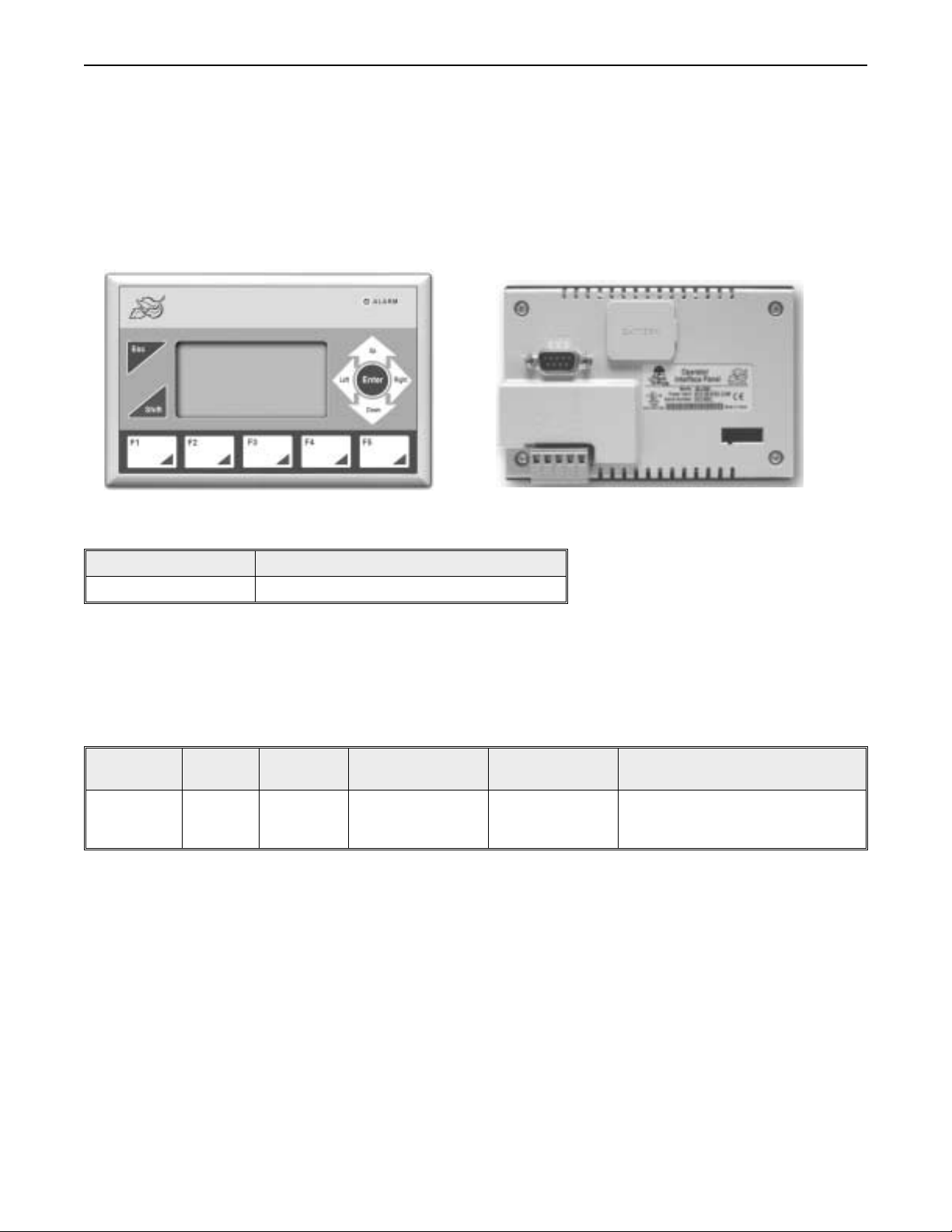
What is a Blue Series OIT?
The Blue Series OITs by Maple Systems are graphics operator interfaces designed to connect to PLCs in an industrial
environment. The 3.0” LCD displays are backlit and have a resolution of 128x64 pixels. The membrane-style keypad is
composed of five function keys (ten with the
built-in clock for displaying time/date and sending this data to the PLC.
SHIFT key) and control keys to facilitate entering data. The Blue Series has a
BLU300M
Front View
LED Indicator Purpose
ALARM LED (red) indicates alarm conditions by the PLC
The Blue Series OIT has two serial ports that provide a connection to a PLC using RS-232, RS-422 or
two wire RS-485. The RS-232 serial port is also used to configure the BLU300.
The Blue Series is powered using +24VDC. Local setup menu allows adjustment of the LCD contrast, a back light saver,
adjustment of the internal clock, and silencing the internal buzzer.
There is currently one model in the Blue Series.
Model
BLU300M 3.0” 128 x 64
Finally, the Blue Series is powered by a 25 MHz, 16-bit microprocessor with 256K Byte of flash memory and 32K Byte of
RAM. The Blue Series is designed for industrial environments and carries a NEMA 4 rating as well as CE compliance for
noise immunity and emissions. It is UL listed.
Display
Size
Resolution LCD Type Keys Clock
STN LCD with
green LED back
light
5 function keys
(10 with Shift)
Back View
Built-in with field-replaceable
battery
1010-0300, Rev 02
Page 9
Introduction 5
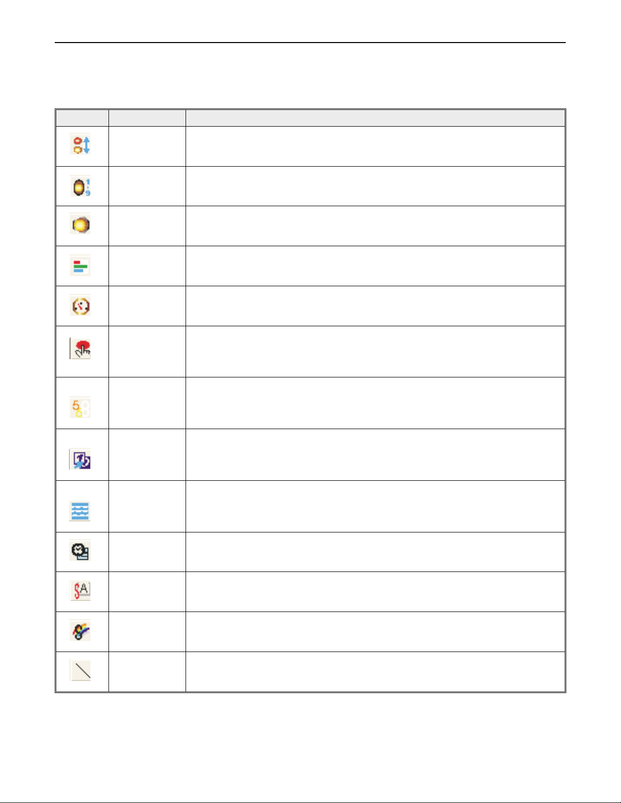
List of Features
The next chapter will guide you through the creation of your first project. Before you proceed, you may wish to read this
brief list of some of the features offered in the Blue Series OIT.
Icon
Bit Lamp Creates a graphics object to reflect the current status of a PLC bit.
Word Lamp Creates a graphics object to reflect the current state of a multi-state PLC data register.
Multi-state Bit
Lamp
Creates a multi-state bitmap object that changes state (picture) according to the value in a
PLC data register. The PLC register can be a coil or 16/32 bit register. Up to 255 states
available.
Bar Graph Creates a bar graph that represents a 16/32 bit PLC register.
Analog Meter Creates an analog meter that represents a 16 bit PLC register.
Function Key Creates a bitmap object, which changes state according to the press of a function key.
Numeric ASCII
display
Numeric Input
Dynamic
Messages
Displays ASCII characters or numbers stored in a PLC register.
Displays a number stored in a PLC register. The number can be changed using the OIT’s
numeric entry screen.
Displays text messages according to a value in a PLC register.
Clock Object
Displays the time and/or date using the built-in clock or data from six consecutive PLC
registers.
Text Object Displays text or symbol characters using windows fonts.
Bitmap Object Displays a predefined or imported bitmap.
Line Draws a line.
1010-0300, Rev 02
Page 10
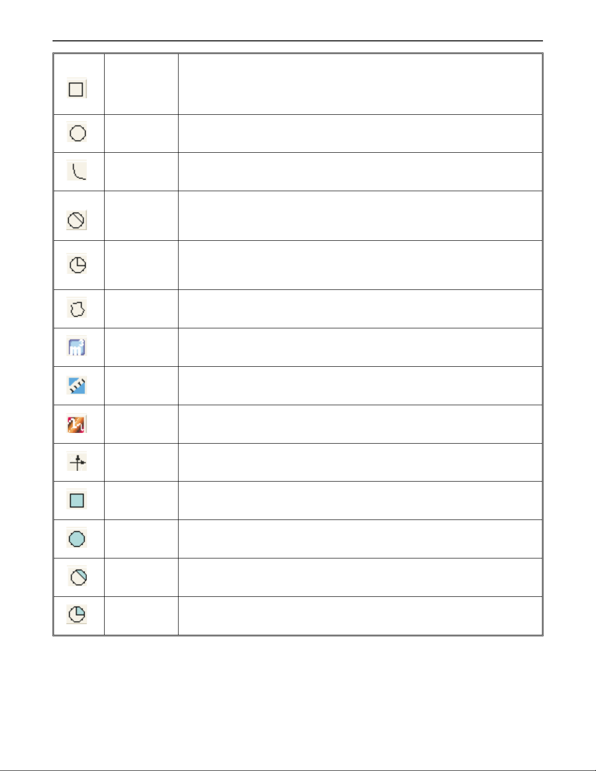
6 Blue Series Installation & Operation Manual
Rectangle
Draws a rectangle or square outline.
(outline)
Circle
Draws a circle or ellipse outline.
(outline)
Curve Draws a curve.
Chord
Draws a chord outline.
(outline)
Sector
(outline)
Draws a sector outline.
Polygon Draws a polygon shape.
Unit of Measure Displays most common units of measure.
Scale Used to display scales (for bar graphs).
Trend Display Creates a trend display to monitor changes to a register.
XY Plot Creates an XY plot to plot various data points.
Rectangle
(Solid)
Circle
(Solid)
Chord
(Solid)
Sector
(Solid)
Draws a filled-in rectangle or square.
Draws a filled-in circle or ellipse.
Draws a filled-in chord.
Draws a filled-in sector.
1010-0300, Rev 02
Page 11

Installation of OITs 7
Chapter 1 - Installation of OITs
Before You Begin
Please read the following for proper handling of your new OIT.
Unpacking the Unit
Carefully unpack the OIT. Please read any instructions or cautions that appear on the shipping container. Check all material
in the container against the enclosed packing list. Maple Systems, Inc. will not accept responsibility for shortages against the
packing list unless notified within 30 days. The equipment and its accessories were inspected and tested by Maple Systems
before shipment; all of the equipment should be in good working order. Examine the equipment carefully; if any shipping
damage is evident, notify the carrier immediately. You are responsible for claim negotiations with the carrier. Save the
shipping container and packing material in case the equipment needs to be stored, returned to Maple Systems, or transported
for any reason.
Managing Electrostatic Discharge
It is best NOT to remove the rear enclosure of the OIT. When the rear part of the enclosure is removed, the circuitry inside is
exposed to possible damage by electrostatic discharge during handling. Minimize the possibility of electrostatic discharge
by:
• Discharging personal static by grounding yourself prior to handling the OIT
• Handling the OIT at a static-free grounded workstation
• Connecting the frame ground () connector of the OIT to a clean earth ground
• Placing the OIT in an anti-static bag during transport
CE Compliance
The Blue Series OITs have been tested to conform to European CE requirements per Council Directive 89/336/EEC. The
European Union created these requirements to ensure conformity among products traded in those countries. Specifically, the
Blue Series OITs meet or exceed the noise emissions and immunity requirements as set forth in the EN50081 (Emissions)
and EN50082 (Immunity) standards. These products are designed to withstand electrical noise in harsh industrial
environments. They also conform to requirements that limit electrical emissions. However, this does not guarantee that the
products will be totally immune from possible malfunction in cases where severe electrical noise occurs. Therefore, we
strongly recommend that you follow the guidelines outlined in this chapter for proper wire routing and grounding to insure
the proper operation of the Blue Series OIT.
NEMA Rating
The Blue Series OITs are rated for NEMA 4/12 or IP65 installations. This means that when the OIT is properly mounted to a
panel or other enclosure, the front enclosure of the OIT will provide protection to the inside of the panel from splashing
water, wind blown dust, rain, or hose-directed water. The OIT must be installed according to the instructions in this chapter
to be properly sealed.
Environmental Considerations
The Blue Series is designed to operate in temperatures from 0-50° C. It is intended primarily for indoor installations and may
not be suitable for certain outdoor applications. Avoid installing the Blue Series in environments with severe mechanical
vibration or shocks. Do not install the OIT in enclosures with rapid temperature variations or high humidity. Either may
cause condensation of water inside the device and eventual damage to the OIT.
1010-0300, Rev 02
Page 12
8 Blue Series Installation & Operation Manual
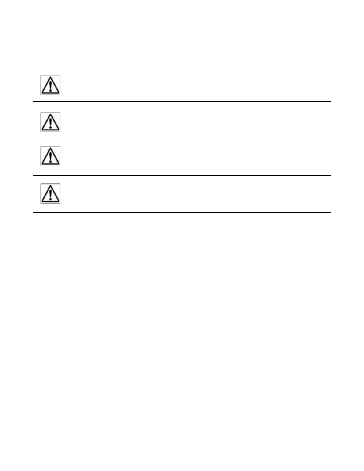
Safety Precautions
Please observe the following precautions when installing the Blue Series OIT. Failure to comply with these restrictions
could result in loss of life, serious personal injury, or equipment damage.
Warning: Do not operate the OIT in areas subject to explosion due to flammable gases, vapors, or
dusts.
Warning: Do not connect the OIT to an AC power source. You will cause permanent damage to
the OIT.
Warning: Do not attempt to use a DC power supply that does not meet OIT power requirements.
You may cause malfunction or permanent damage to the OIT.
Warning: Do not power the OIT with a DC power supply used for inductive loads or for input
circuitry to the programmable logic controller. Severe voltage spikes caused by these devices may
damage the OIT.
1010-0300, Rev 02
Page 13
Installation of OITs 9
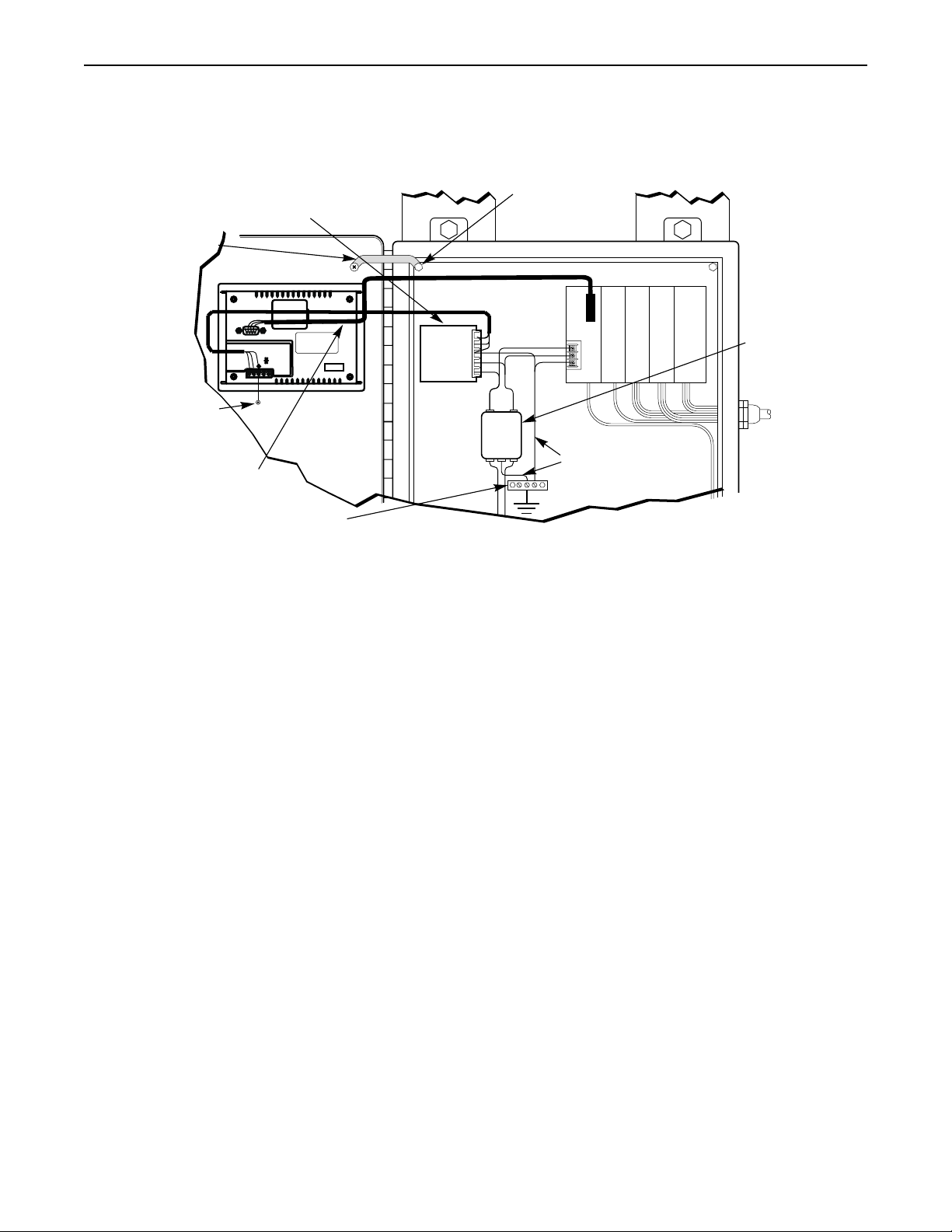
Control Panel Design Guidelines
Pay careful attention to the placement of system components and associated cable routing. These items can significantly
enhance the performance and integrity of your control application.
Control panel is
Shielded power cable
Ground
strap
OIT
(rear side)
Shielded DB9P
BATTERY
male connector
RS-485
-
0V
+24V
+
OIT is
grounded to
control panel
Shielded
communication
cable
Quiet ground
EXTENSION
OIT
Power
PORT
Supply
tied to a reliable
earth ground
Line
Filter
PLC/Host
I / O control lines
Ground wires
Quiet ground
(isolated)
Power
line
filter
Control Panel Example
Control Panel Grounding
The control panel should be connected to a good, high-integrity earth ground both for safety considerations and shielding
purposes. Maple Systems cannot overemphasize the importance of good grounding. If you fail to use good grounding
procedures during installation, sporadic malfunction of the OIT may occur:
• Connect the OIT’s chassis ground terminal to a reliable earth ground with a low-resistance path.
•
Route all earthground wires thatlead from the OIT, the PLC, the power supply, and the line filterto a central
earth ground point such as a barrier strip. This will ensurethat no ground current from onedevice influences
the operation of the other devices.
•
Connect the OIT chassis ground terminal to the control panel door using a heavy-gauge short braided cable
or ground wire to minimize resistance.
•
Connect the power cable’s shield wire to the OIT’s chassis ground terminal.
•
Connect the controlpanel to earth groundusing a copper grounding rod close tothe OIT and controlpanel.
Hinged doors on control panels do not provide a long-term electrical connection to the rest of the enclosure. Corrosion
develops over time and prevents good electrical contract. For this reason, a separate wire braid should be installed from the
hinged control panel to the rest of the enclosure.
For a more in-depth overview of ground wiring techniques, refer to technical note #1027, OIT Ground Wiring and Electrical
Noise Reduction, which you can find at www.maple-systems.com.
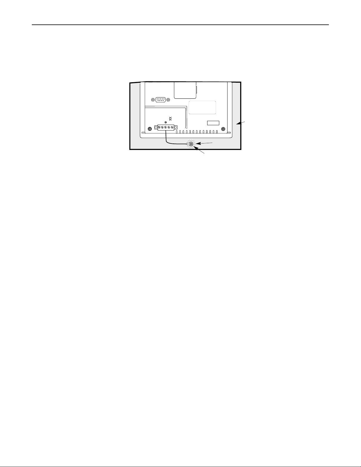
Connect OIT Chassis Ground to Control Panel
To reduce the possibility of electrical interference, connect the chassis ground terminal of the OIT to a clean earth ground. If
the control panel is metal, make sure it is properly grounded. Then connect a short heavy-gauge wire (#18 AWG) from the
chassis ground terminal of the OIT to a mounting bolt on the control panel door. The mounting bolt must have good
electrical contact to the control panel; scrape away any paint that may be covering the panel to provide a good connection.
1010-0300, Rev 02
Page 14
10 Blue Series Installation & Operation Manual
If the control panel is made of a non-conductive material, it is essential that you connect the chassis ground terminal of the
OIT to a clean earth ground point located close to the panel.
0V
+
(rear side)
BATTERY
RS-485
-
BLU300
EXTENSION
PORT
Area on panel
free of paint
Stud or screw
Control panel
(connected to
earth ground)
Shielded DB9P
male connector
+24V
OIT Chassis Ground Connection
Power Supply Selection
The power supply used to power the OIT should provide an output of +24 VDC 5% measured at the OIT power terminal
block. A 24VDC regulated power supply dedicated to the OIT is required (refer to Appendix A: Specifications for the input
current requirements).
The power cable for the OIT should be 18AWG, 2-conductor wire with a shield drain wire and protective shield (foil or
braid). The shield drain wire must be connected to earth ground at both ends of the cable. Please refer to the Connect the OIT
to Power section for more information.
A power line filter installed at the AC input to the OIT power supply is highly recommended as a safeguard against
conducted RF noise, which is often present on factory power lines. The wires connecting the output of the power line filter to
the power supply should be kept as short as possible to minimize any additional noise pickup. The case of the power line
filter should be connected to a quiet earth ground. The power line filter should have a current rating of at least 1 Amp with
common mode and differential mode attenuation.
1010-0300, Rev 02
Page 15
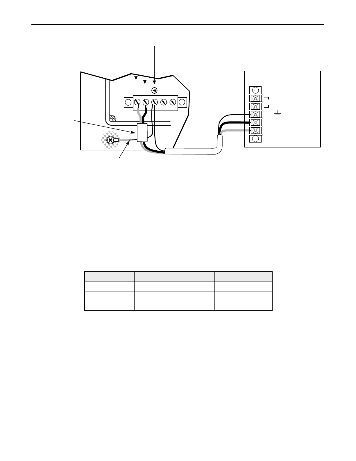
Installation of OITs 11
Do not use the power supply used to provide power to the OIT to power switching relays, solenoids, or other active devices.
Shield wire (bare)
Black wire (-)
Red wire (+)
BLU300 OIT
(rear side)
24Vdc
power supply
Ferrite coil
Control
panel
Shield wire runs
outside ferrite coil
+24V
0V
+
-
120Vac
Shield drain
Black
Red
FG
DC Output -V (Gnd)
DC Output +V (+24V)
OIT Power Inputs
4STEPS:
1. Connect the power cable to the OIT as follows:
A. Strip the power cable shield to expose 2” of the black and red wires.
B. Strip about ¼” of insulation from the black and red wires.
C. Thread the black and red wires through the ferrite core. The shield wire must be outside.
D. Connect the red wire to the DC positive (+) input of the OIT power terminal.
E. Connect the black wire to the DC negative (-) input of the OIT power terminal.
F. Connect the power cable shield wire to the OIT power terminal’s chassis ground input.
2. Route the power cable to the OIT power supply. The power cable should not be any longer than
necessary.
3. Install the power supply wires as follows (with colors shown for Maple Systems cable P/N
6030-0009):
Color Power Supply BLU300 Label
Red +Output/+24 V dc +24V
Black -Output/+24V dc return 0V
Shield Case ground
0 FG
1010-0300, Rev 02
Page 16
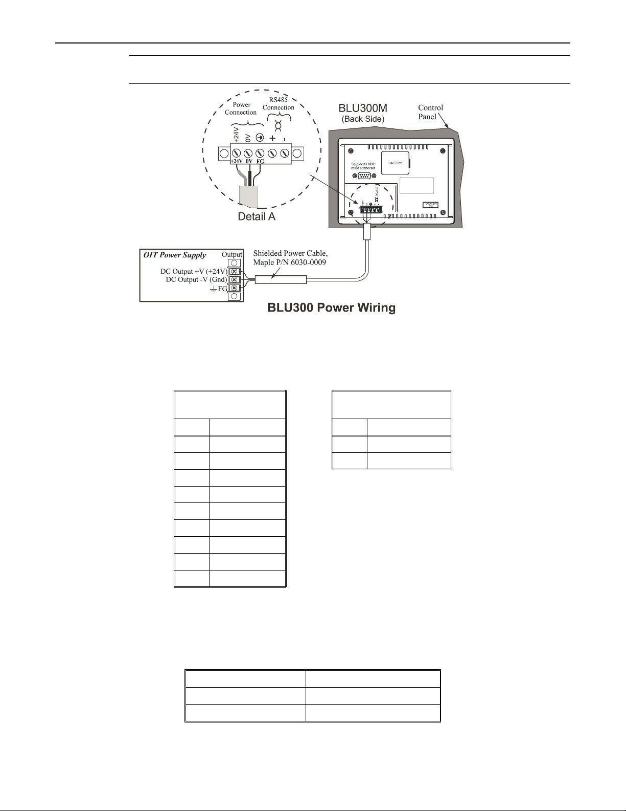
12 Blue Series Installation & Operation Manual
* The power connector on the BLU300 Series is a terminal block with wire clamps. Lugs are not
required.
Connect the OIT to the PLC
Each PLC supported by Maple Systems has its own wiring requirements. Maple Systems offers OIT-to-PLC communication
cables for most PLCs that are built to any length and tested for high reliability. Most cables are available for next-day
shipment from Maple Systems. Components and instructions necessary to construct your own OIT-to-PLC communications
cables are also available. Refer to Maple Systems’ website.
Port 1
RS-232/RS422
Pin # Function Pin # Function
1 (no connection) + RXD+/TXD+
2 RXD - RXD-/TXD-
3 TXD
4 (no connection)
5 GND
6 RX (+)
7 RX (-)
8 TX (+)
9 TX (-)
Port 2
RS-485
Pinout for the OIT Ports
Selecting RS-422 or RS-485:
•
Remove battery cover on rear cover and set dip switches as follows:
1010-0300, Rev 02
RS-485 RS-422
1-4 (on) 1-4 (off)
5-8 (off) 5-8 (on)
Page 17

Installation of OITs 13
r
Port 1, PC[RS-232]/PLC[RS232]/PLC[RS422],
has a shielded male DB9P connector
Tighten all screws
Control panel
4STEPS:
PLC/
Host
Earth
GND
Attach earth ground wire
Port 1
PLC[RS-232]/[RS-422]
PC[RS-232]
+24V
BATTERY
Port 2
RS-485
-
0V
+
PLC[RS-485]
EXTENSION
PORT
(if included on cable)
2-Wire RS485
Communication cable specific fo
the PLC/Host; twisted pair, foil
shielded, 28AWG minimum
Power & 485 Comm. connector
5-Pin Phoenix removable terminal
OIT
Power
Supply
Shielded power cable
Output
FG
block connector, 0. 20” [5.08mm] ctrs.
1. Connect the “HMI” end of the communication cable into either the RS-232/RS422 port or the RS-485
port as required for your application (HMI housing is marked).
2. Tighten the two cable screws at each end to ensure shield ground path.
3. Route the communication cable to the PLC. Refer to the “OIT Cable Routing” section for more
information.
4. Connect the “PLC” end of the cable to the PLC and tighten the cable screws.
5. Connect the green shield wire from the cable to earth ground (
0) on the PLC. If this wire is not
present, make the ground connection inside the PLC connector.
Panel Preparation
A metal panel or mounting surface with a minimum thickness of 15 gauge (0.059 inch/3.3mm) if cold-rolled steel or
hardened steel, or 10 gauge (0.101 inch/2.6mm) if aluminum alloy (6061-T6 preferred) is required. Thinner panels or
surfaces may bow between the mounting clamps and not form a seal with the gasket.
The area of the panel or mounting surface where the gasket comes into contact must be flat and free of scratches, pits, and
other features that prevent the gasket from sealing properly. If the panel or mounting surface is not uniform, thick, flat, stiff,
or smooth enough, then a sealant such as silicone may be required.
* Clean and deburr the panel cutout before the OIT is installed.
WARNING
The OIT requires a stiff, flat, smooth mounting surface
free of blemishes to seal properly to NEMA 4.
1010-0300, Rev 02
Page 18

14 Blue Series Installation & Operation Manual
Mount the OIT to the Panel
Installing the Screws on the OIT
4STEPS:
1. Prepare the four screw clamps for the BLU300 by inserting the clamps into the slots of the back
enclosure as show in the illustration above.
2. Snap the OIT into the panel cutout using the plastic brackets of the back enclosure. Make sure that all
metal clamps are properly in position.
3. Tighten the screw clamps until all are uniformly snug.
CAUTION: Do not over-tighten the screws beyond snugness, or you may damage the housing.
REINSTALLATION: Because the gasket will take a “set” to the panel, be sure to reinstall the OIT to the same panel cutout
when a NEMA 4 seal is required. For best results, also replace the gasket itself.
Configuration Wiring
The OIT must be configured for a particular protocol before use. The BlueLeaf software (used on a PC with Windows 95 or
higher) is used for configuring the OIT. For detailed instructions on installing and using the software, please refer to the
software documentation section of this manual.
Connect the OIT to the PC for Configuration
To configure the OIT using Maple System’s configuration software, you will need the OIT Configuration Cable, Maple P/N
7431-0102. Connect the end marked “HMI” into the RS-232 port on the OIT and connect the end marked PC into the proper
1010-0300, Rev 02
Page 19
Installation of OITs 15
COM port on your PC. See the figure below for serial port pin assignments and the next two figures for connecting the
BLU300 series to a PC.
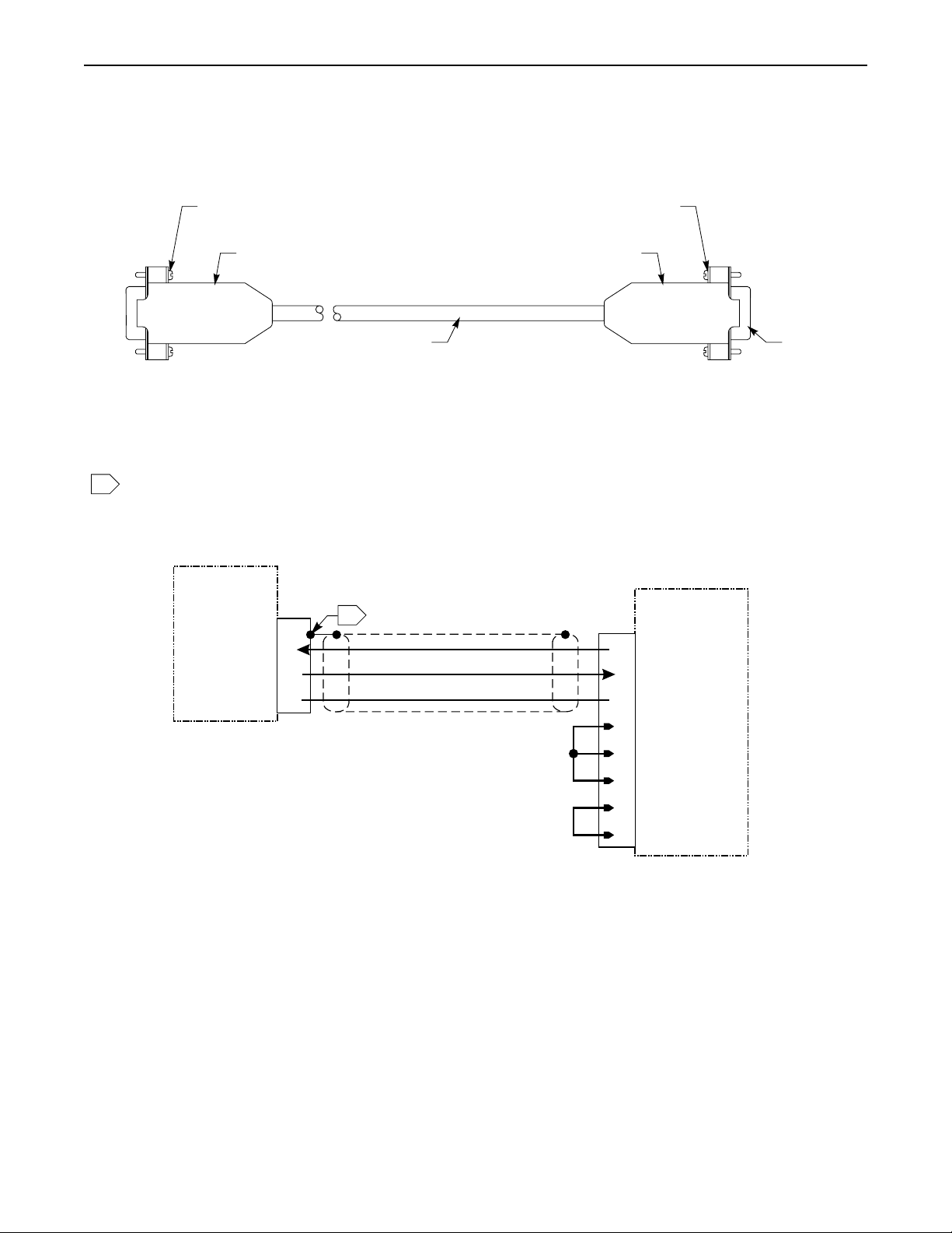
BLU300 SERIES CONFIGURATION CABLE
OIT END
NOTES:
Solder shield wire to the DE9P connector metal shell. Install
1
heatshrink tubing over the shield wire to avoid shorting.
4-40 x 1/2 Retainer
Screw, 2 places
DE9S Connector
& DE9 Backshell
24 AWG Shielded cable
OIT
9S
RXD
TXD
Return
2
3
5
4 Conductor
1
4-40 x 1/2 Retainer
Screw, 2 places
DE9 Backshell
9S
3
DE9S
Connector
PC END
PC
TXD
RXD2
GND5
DCD
1
DTR
4
DSR
6
RTS
7
CTS
8
1010-0300, Rev 02
Page 20
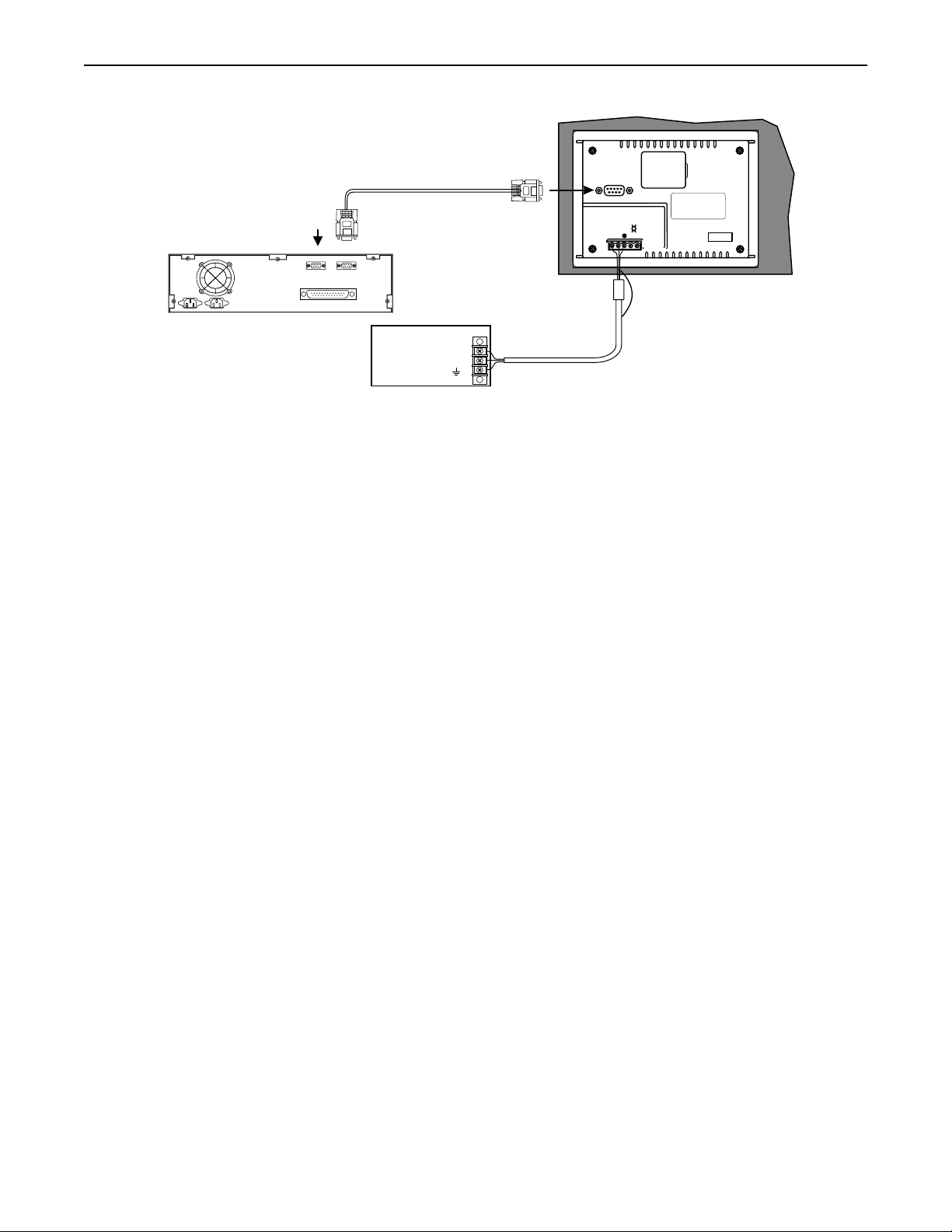
16 Blue Series Installation & Operation Manual
Maple Systems OIT
programming cable,
P/N 7431-0102
Shielded DB9P
male connector
BATTERY
(If mouse is using
Com 1, use Com2)
PC
Com2 Com1
RS-485
-
0V
+24V
+
EXTENSION
PORT
BLU300M
Printer
OIT Power Supply
DC Output +V (+24V)
DC Output -V (Gnd)
Output
FG
Connectingthe BLU300M to a PC
Shield
(outside ferrite core)
Factory Configuration
Each OIT arrives from the factory without a project file in the OIT. To use the OIT, you must first create a project , then
download the project to the BLU300. Please follow the directions enclosed in Chapter 2, Creating Your First Project,to
configure your OIT for the PLC that you are using.
Each OIT has local setup menus that allow you to adjust some of the settings of the BLU300. Use the local setup menu to:
• Set OIT comm port settings
• Adjust the contrast setting of the LCD display
• Set a time interval for the back light saver
• Set the internal clock
• Enable the internal buzzer
• Select language
• Assign a password to prevent unauthorized access of the local setup menus
• Assign the startup screen
The BLU300 comes with a CR2032 battery for the built-in clock. If the battery needs replacing, please follow the steps
below:
4To change the clock battery:
1. Use a small screwdriver to remove the battery cover on the back enclosure of the OIT.
2. Push the metal side lever to spring the battery loose.
3. Install a new lithium battery (CR2032) into the battery socket, ensuring the + side of the battery is
facing up.
4. Snap the battery cover onto the back enclosure of the OIT.
5. Reset the time, day of week, and date of the clock by entering the local setup menus (see Chapter 4:
Basic Operation of the BLU300).
1010-0300, Rev 02
Page 21

Creating Your First Project 17
Chapter 2 - Creating Your First Project
Often the best way to learn about new software is to just jump right in. This chapter will step you through the process of
installing the BlueLeaf configuration software and then using the software to create a sample project that can be downloaded
to your OIT. We won’t go into much detail as to how each feature works. The purpose of this chapter is only to provide you
with an overview of the process of creating a functional OIT that can communicate to a PLC. For our sample project, we
will configure the OIT using the Modbus RTU protocol but you may feel free to select whichever protocol driver you intend
to use.
By the end of this chapter, you should be able to:
Install and start the BlueLeaf configuration software.
Create a sample project with two screens and several graphics objects.
•
Save a project, compile a project, and download the project to the OIT.
•
Verify that the OIT is functioning properly.
•
Before You Begin
Before you install BlueLeaf, make sure your computer meets the following minimum system requirements:
Pentium-based 90MHz or higher processor
•
• 16 MB of RAM (more memory improves performance)
• 10 MB available hard disk space
• VGA or higher-resolution monitor set for 256 color 800x600 pixel mode
• Microsoft Mouse or compatible pointing device
• One available RS-232 port
• Microsoft Windows 95, 98, NT or higher
Connecting OIT to Computer
Before you start your first project, the OIT should be connected to the computer so that the project can be downloaded after
creating it. You should also connect the PLC that you are using to the OIT so that you can test the operation of the OIT after
you have finished creating this sample project.
4To connect your OIT to the computer
1. Connect a +24VDC power supply to the OIT.
2. Connect the programming cable (Maple P/N 7431-0102) to the computer and OIT.
•
Connect the end marked HMI to the OIT port labeled RS-232/RS422.
•
Connect the end marked PC to the COM port of the computer.
3. Apply power to the OIT.
4Setting the PC COM Port used by BlueLeaf
BlueLeaf is initially configured to use Com Port 1:
1. In Windows, click the Start button.
2. Select Programs.
3. Select Maple Systems.
4. Select BlueLeaf. The BlueLeaf application software will activate.
5. Open an existing project, or create a new one.
6. Click the
7. Select the HMI Comm Addr of 1-255 (Default setting is 1 on the BLU300)
8. Select a COM Port: 1-8
9. Select baud rate (use 115200 unless you have problems downloading to the OIT)
10. Click Enter.
OPTIONS menu, then click PC-HMI Settings.
1010-0300, Rev 02
Page 22
18 Blue Series Installation & Operation Manual
4To connect your PLC to the OIT
1. Download your project to the Blue Series OIT.
Maple Systems produces PLC communications cables that will connect the OIT to most of the PLCs
available. The cables can be manufactured to any length you require. A listing of all the PLC cables
Maple Systems offers, along with cable drawings, can be found on our website.
2. Connect the PLC communications cable from the serial port on your PLC to the appropriate serial port
on your OIT.
If you are using RS-232 or RS-422 communications, then connect the OIT end of the cable to the OIT
•
port labeled RS-232/RS-422.
If you are using RS-485 communications, then connect the OIT end of the cable to the OIT port labeled
•
RS-485.
3. Apply power to the PLC. Apply power to the OIT. The OIT will display the startup screen.
Starting BlueLeaf
Before you can create a sample project, you must start the configuration software. The BlueLeaf software is very easy to
operate:
4To start the BlueLeaf software
1. From the Windows Task Bar, click the Start button, point to Programs, and then click the
SYSTEMS
2. Click BlueLeaf to start the application.
3. Select File Open or File New to begin a project.
4. The main screen of BlueLeaf is displayed with Screen 0.
folder.
MAPLE
1010-0300, Rev 02
Page 23
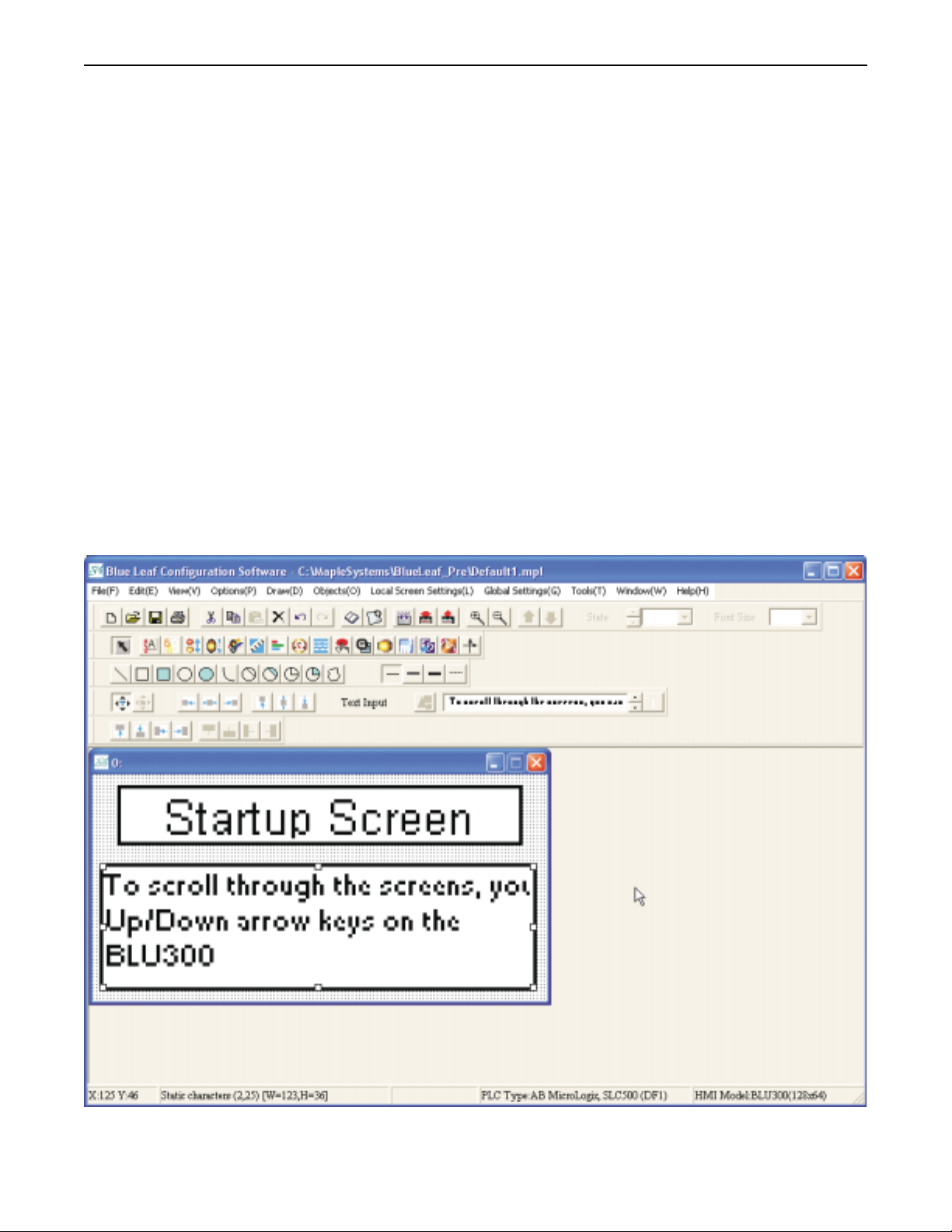
Creating Your First Project 19
The following illustration shows the various sections of BlueLeaf.
Creating a Sample Project
This section walks you through the creation of a BlueLeaf project named Sample.mpl. Once downloaded to the OIT, this
basic configuration allows the OIT to connect to the PLC, display a startup screen, and display a screen containing one PLC
register monitor when a switch on the startup screen is pressed.
Although we strongly recommend that you perform the following steps to create this sample project, the project is already
included in your BlueLeaf software with the following filename:
SAMPLE.MPL-sample project for the BLU300M
1010-0300, Rev 02
Page 24
20 Blue Series Installation & Operation Manual
Selecting the PLC
Whenever you begin a new project, you need to select which PLC you intend to use and the name of the project:
4To select a PLC and start a new project:
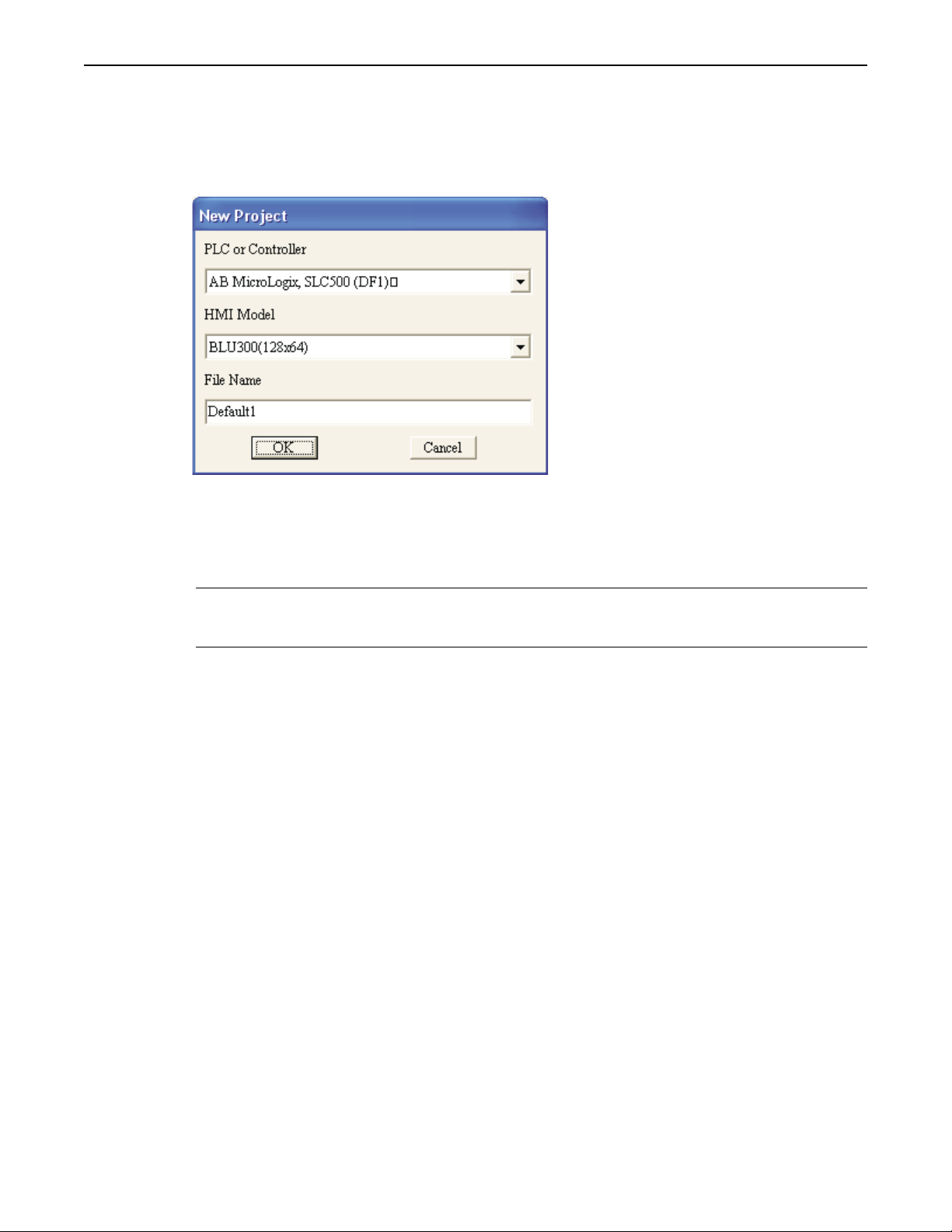
1. Click the
FILE menu, then click New.
2. Select the PLC or controller that you are using from the PLC or Controller pull-down box.
3. Select the HMI Model (at this time, the only model selectable is BLU300).
4. Enter the name you have chosen for your project in the File Name box (in this example, enter
SAMPLE). Note: the default extension is MPL.
5. Click OK to return to the BlueLeaf main screen.
* The communications parameters for the RS-232 port or RS-485/RS-422 port of the OIT are
configured from the Tools…HMI-PLC Comm Settings dialog box. Select the communications
port you intend to use in Tools…HMI Default Settings.
Creating Two Screens
Screen #0, by default, is created when you start a new project. The OIT can store up to 999 predefined screens (actual
number of screens dependent upon memory used) but you have to create them. To create Screen #1, you must perform the
following:
4To create Screen#1:
1. From the
2. Screen #1 is created and displayed as the active screen in BlueLeaf.
3. For now, click on Screen #0 to make it the active screen.
Creating a Startup Screen
We will configure Screen #0 as the startup screen. This section will show how to place text in the screen and how to create a
function key that will display Screen #1.
EDIT menu, click Add New Screen.
4To place text on Screen#0:
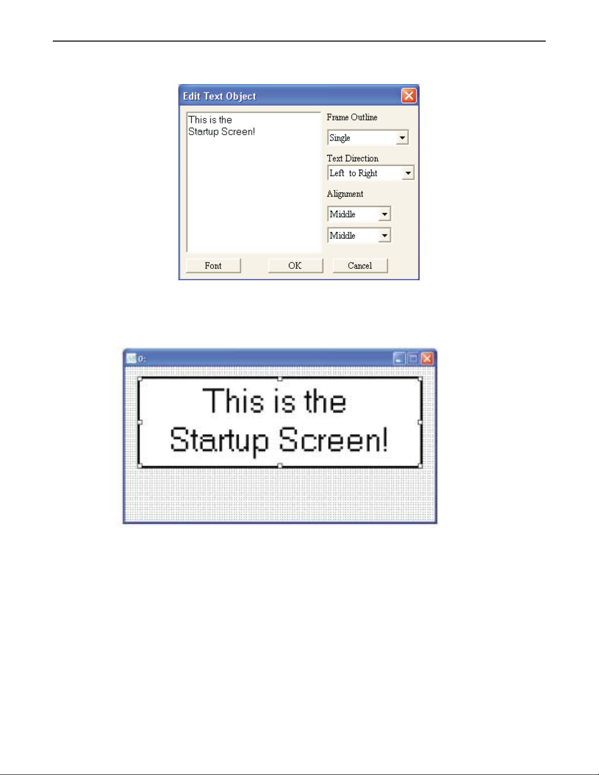
1. From the
2. Move the mouse cursor over the work area. The cursor changes from an arrow to a crosshair pointer.
3. Click once on Screen #0 to place a text object.
4. Double-click on the text object to display the
5. Click the Font button. Select MS San Serif Regular 10 in the
6. Click Single in the
7. Click Left to Right in the
8. Select Middle for both
DRAW menu, click Text.
EDIT TEXT OBJECT dialog box.
FONT dialog box. Then click OK.
FRAME OUTLINE pull-down box.
TEXT DIRECTION box.
ALIGNMENT boxes.
1010-0300, Rev 02
Page 25
Creating Your First Project 21
9. Click in the content box and type This is the Startup Screen!. Split the sentence into two lines as
shown:
10. Click OK.
11. On the main screen of BlueLeaf, you will see the text object with small white boxes around the
perimeter. Move your mouse cursor over these boxes and click/drag to resize the text object.
12. Move the mouse cursor over the text box and click/drag to move on Screen 0 as shown:
4To create a visible function key on Screen#0:
1. From the
2. Move the mouse cursor over the work area. The cursor changes from an arrow to a crosshair pointer.
3. Click once on Screen #0 to place a function key object.
OBJECTS menu, click Function Key.
1010-0300, Rev 02
Page 26
22 Blue Series Installation & Operation Manual
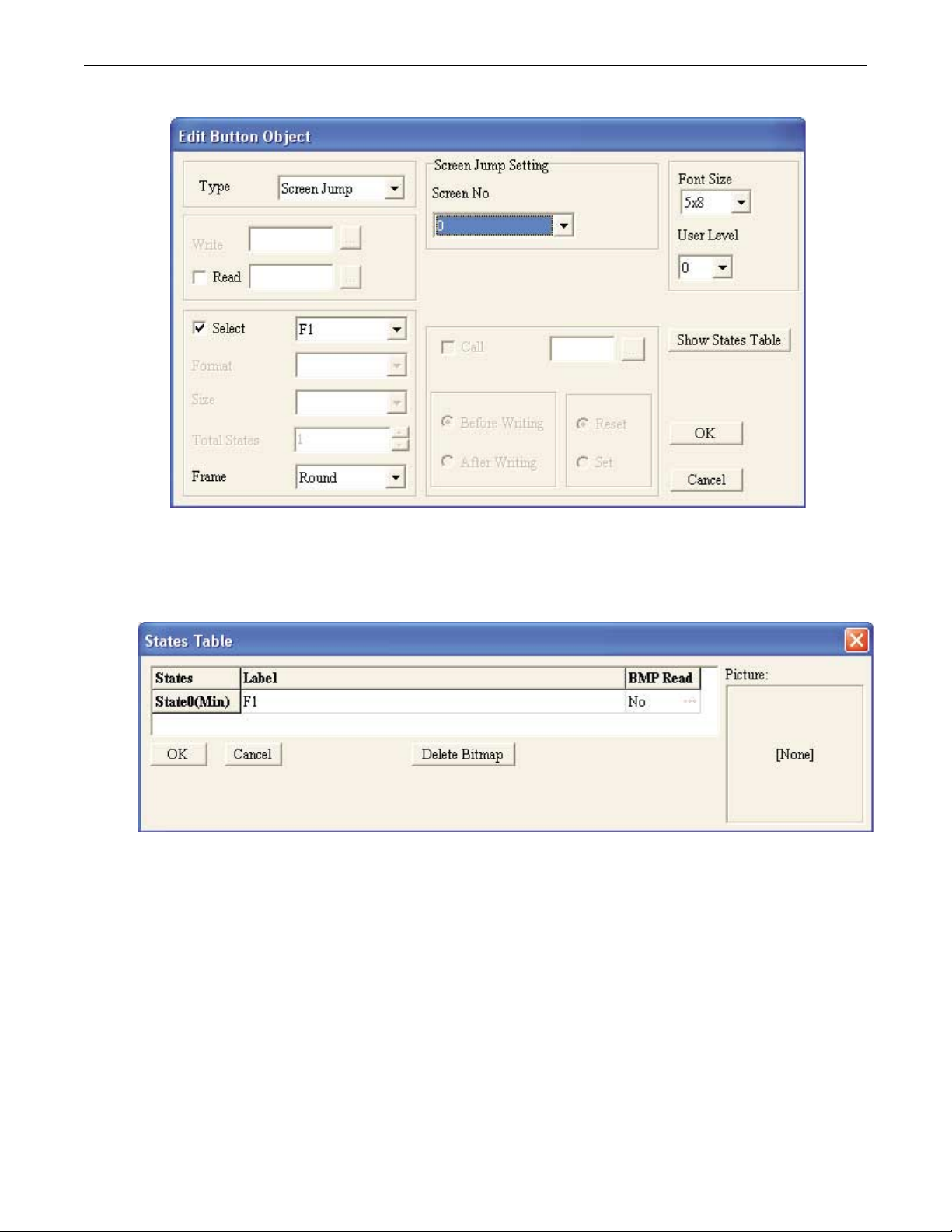
4. Double-click on the function key object to display the EDIT BUTTON OBJECT dialog box:
5. Click the Type pull-down box and select Screen Jump.
6. In the Screen Jump Setting frame box, select 1 from the Screen No. pull-down box.
7. Check the Select checkbox, then select F1 from the pull-down box.
8. In the Frame box, select Round.
9. Click the Show States Table button:
10. Click on the Label entry and type F1.
11. Click the OK button to go back to the Edit Button Object dialog box.
12. Click OK to go back to Screen 0.
13. On the main screen of BlueLeaf, you will see the function key object with small white boxes around
the perimeter. Move your mouse cursor over these boxes and click/drag to resize the function key
object.
1010-0300, Rev 02
Page 27
Creating Your First Project 23
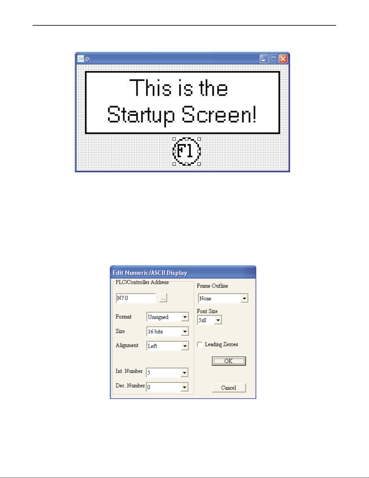
14. Move the mouse cursor over the function key box and click/drag to move on Screen 0 as shown:
Creating a Second Screen
We will configure Screen #1 to display a PLC register. You will also create an increment and decrement key to change the
value in the PLC Register.
Click on Screen 1 that you created earlier.
4To create a numeric register on Screen#1
1. From the
2. The mouse cursor changes to a crosshair. Select the location on the screen to place the
Numeric/ASCII Display and left click the mouse to place a Numeric/ASCII Display object on the
screen. Move the mouse cursor over the Numeric/ASCII Display object and double-click the
Numeric/ASCII Display object. The Edit Numeric/ASCII Display Object dialog box appears.
OBJECTS menu, click Numeric/ASCII Display.
3. Enter the data as shown above (for more details on using the Numeric/ASCII Display object, consult
Chapter 8: Entering and Displaying Numeric and ASCII Characters.)
4. Click OK. The Numeric/ASCII Display Object is displayed on the main screen of BlueLeaf as a
numeric value of 0. If necessary, use the mouse to drag the object to the location on the window that
you want it. You can also highlight the object to display the small white perimeter boxes and adjust
1010-0300, Rev 02
Page 28
24 Blue Series Installation & Operation Manual
the size. Simply move the mouse cursor over the appropriate white box until the mouse cursor changes
to a double-arrow symbol, then click and drag to change the size.
4To create an increment key on Screen#1
1. From the
2. Move the mouse cursor over the work area. The cursor changes from an arrow to a crosshair pointer.
3. Click once on Screen #1 to place a function key object.
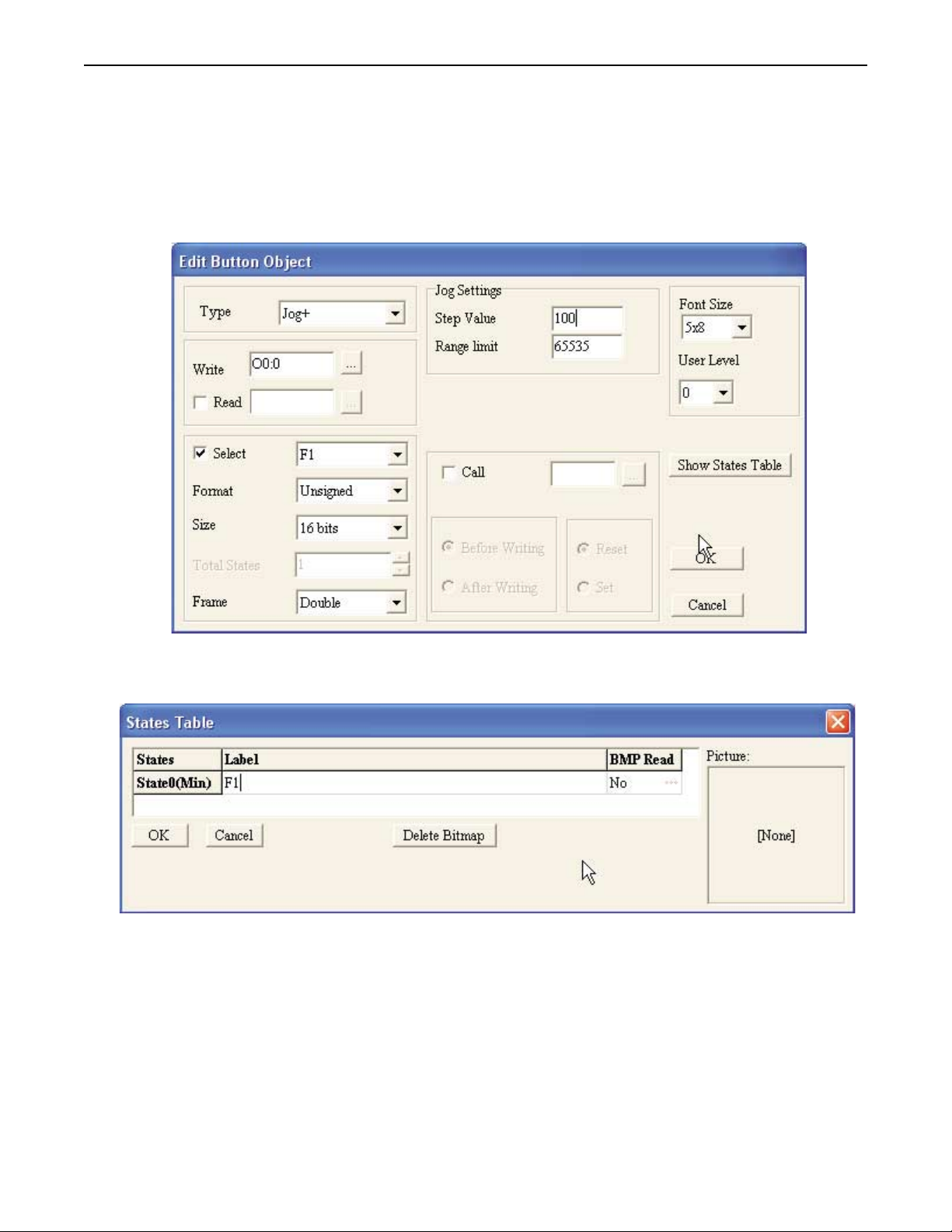
4. Double-click on the function key object to display the Edit Button Object dialog box:
OBJECTS menu, click Function Key.
5. Enter the data as shown above (for more details on using the Function Key object, consult Chapter 9:
Using the Function Keys.)
6. Click the Show States Table button:
7. Click on the Label entry and type F1.
8. Click the OK button to go back to the Edit Button Object dialog box.
9. Click OK to go back to Screen 1.
10. On the main screen of BlueLeaf, you will see the function key object with small white boxes around
the perimeter. Move your mouse cursor over these boxes and click/drag to resize the function key
object.
11. Move the mouse cursor over the function key box and click/drag to move on Screen 1.
4To create a decrement key on Screen#1
1. Click on the F1 key you just created to highlight it.
2. From the
3. From the
key.
EDIT menu, click Copy.
EDIT menu, click Paste. A copy of the increment key appears directly on top of the initial F1
1010-0300, Rev 02
Page 29
Creating Your First Project 25
4. Use the mouse cursor to click and drag the second F1 key to the right of the first F1 key.
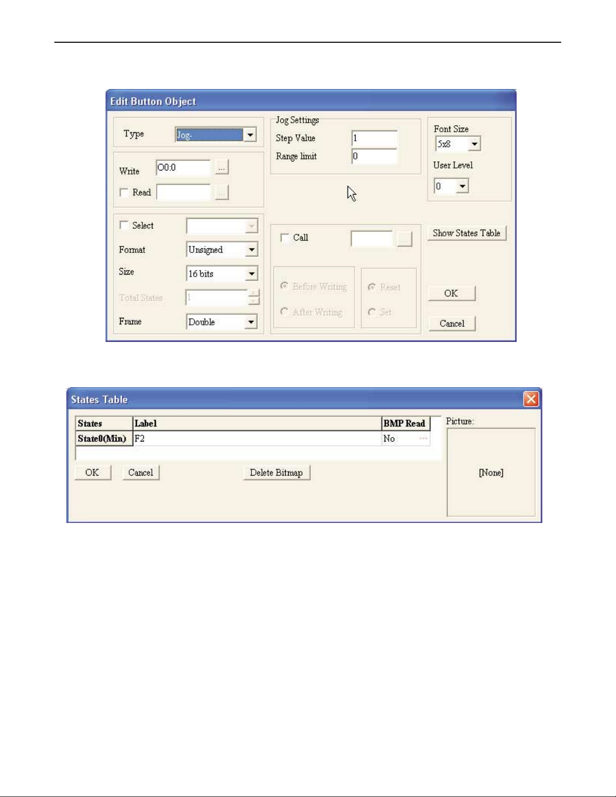
5. Double-click on the second increment key. The Edit Button Object dialog box appears:
6. Enter the data as shown above (for more details on using the Function Key object, consult Chapter 9:
Using the Function Keys )
7. Click the Show States Table button:
8. Click on the Label entry and type F2.
9. Click the OK button to go back to the Edit Button Object dialog box.
10. Click OK to go back to Screen 1.
1010-0300, Rev 02
Page 30
26 Blue Series Installation & Operation Manual
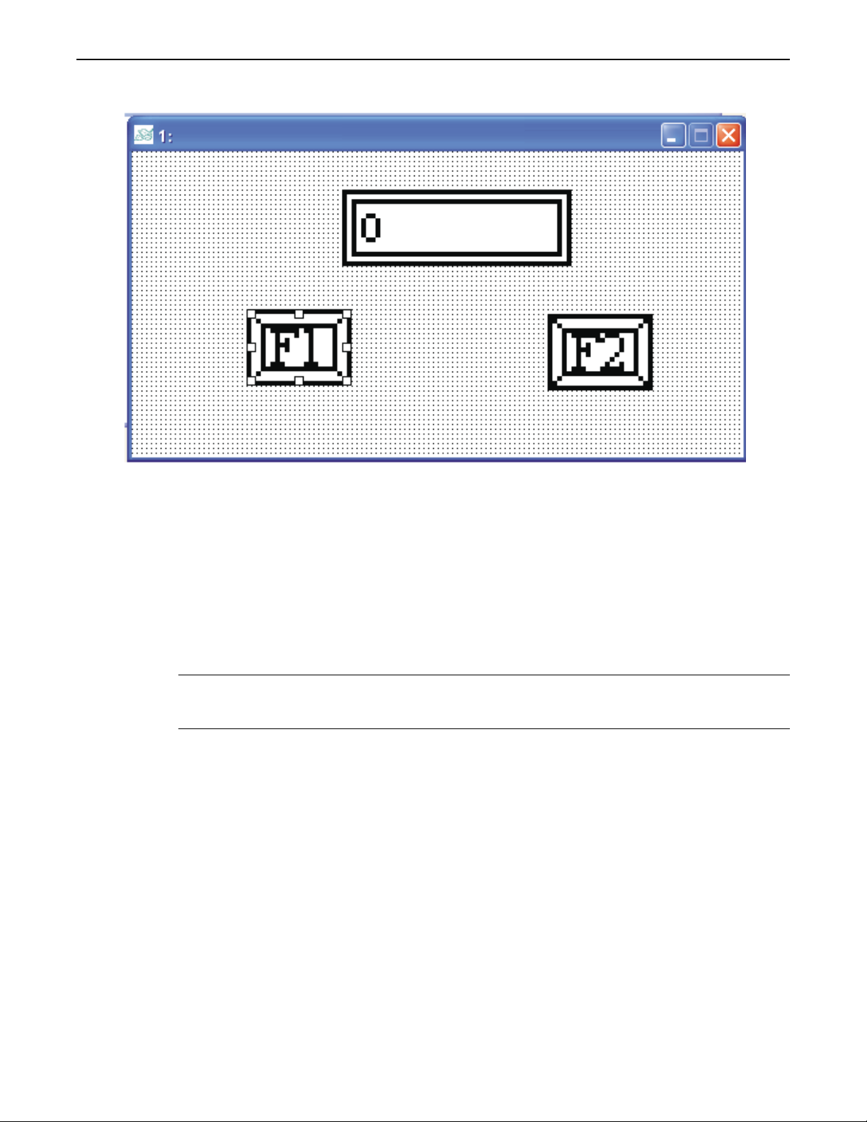
The following illustration shows how Screen #1 looks:
You have now done your part in creating this sample project. It is now time for BlueLeaf to do its part.
Finishing Up
There are still a few steps, which must be completed before you can test your first project. In this section, you will:
• save the project onto your computer hard drive
• compile the project into a format that can be understood by the OIT
• download the project to the OIT
• verify that the OIT operates as expected
•
exit the BlueLeaf software
* If you haven’t already done so, now would be a good time to connect the OIT to the computer.
For more information, consult the first part of this chapter or see “Installation of OITs” later on
in this manual.
4Saving your first project
1. From the
2. Click OK. The file is saved onto your computer hard drive.
FILE menu, click Save.
4Compiling your first project
1. From the
2. Click OK.
TOOLS menu, click Compile. BlueLeaf will compile your project and display error results.
4Downloading your first project
1. Apply power to your OIT, while holding down the
2. Continue holding down the
3. On the OIT, press the F1 key to select 1.Read from PC.
4. From the
5. On the OIT, press the
6. Click Yes on the BlueLeaf dialog box to begin download.
7. When the download is complete, click OK.
TOOLS menu of BlueLeaf, click Write Project to BLU300. The Confirm dialog box appears.
ESC key until the Local Setup menus appear on the OIT screen.
ENTER key to receive a download file.
ESC key.
1010-0300, Rev 02
Page 31

Creating Your First Project 27
4Displaying your project on the OIT
1. Press the
2. Disconnect the OIT from the computer, and connect to your PLC.
3. Press the F5 function key to move the blinking cursor to 5.EXIT&RUN.
4. Press the
5. The OIT should display the following screen.
6. Press the F1 function key to display Screen #1:
ESC key on the OIT to exit the download screen.
ENTER key.
7. Press the F1 key to increment the value in the Numeric Display object. Press the F2 key to decrement
the value in the Numeric Display object.
CONGRATULATIONS! You have completed your first BlueLeaf project.
1010-0300, Rev 02
Page 32

Using BlueLeaf Software 29
Chapter 3 - Using BlueLeaf Software
Overview
The BlueLeaf software is used to create a project file that can be downloaded into the BLU300 operator interface terminal.
This chapter shows you how to maneuver around BlueLeaf easily. This will pave the way for actually creating graphics
objects in later chapters.
The BlueLeaf Application
This section guides you in how to operate the BlueLeaf application; however, it does not show you how to program your
OIT or how to create graphics objects. These topics are reserved for later chapters. This section shows the fundamental
operation of BlueLeaf -- from saving files, printing projects, and selecting the target PLC to showing how graphics objects
can be easily manipulated in the BlueLeaf work area. When you have completed this chapter, you will be better able to use
the features that are explained in later chapters.
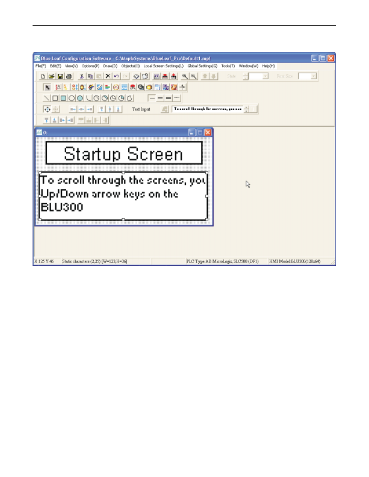
The following illustration is used for reference to the following sections:
1010-0300, Rev 02
Page 33

30 Blue Series Installation & Operation Manual
Managing Projects
Like most Windows®application software, BlueLeaf will open, save, close, and print files using the standard windows
format.
Opening, Editing Projects
4To create a new project
1. On the
FILE menu, click New or click the New icon in the Standard toolbar. The New Project dialog
box appears:
2. Select the HMI model you intend to use with your project (the BLU300 is the only model available in
this version).
3. Select the PLC or controller.
4. Enter the name for your project under File Name.
5. Click OK. The main screen of BlueLeaf appears with a blank work area.
1010-0300, Rev 02
Page 34

Using BlueLeaf Software 31
4To open an existing project
1. On the
appears:
FILE Menu, click Open or click the Open icon in the Standard toolbar. The Open dialog box
2. Click on the project file you intend to open.
3. Click Open. The main screen of BlueLeaf appears with the initial screen of the project displayed.
4To close a project
On the
FILE menu, click Close. If changes have been made to the project file, BlueLeaf will ask you if you would like to
save the project. Then the main screen of BlueLeaf will remain but with no work area displayed. You must now use the
Open or New commands to edit a project.
4To save an existing project
1. On the
2. The project will automatically be saved using the file name you assign when you first created the
3. To save the file under a new file name, click Save As on the File menu, and then enter a file name.
4. The main screen of BlueLeaf reappears.
4To save a specific screen
1. On the FILE menu, select Save Screen Image.
2. To save the screen image to the clipboard, for pasting in another document, select To Clipboard. To
System Screens
BlueLeaf has 20 system screens it uses to display various comments, errors, fields, menus etc.
4 To edit system screens
1. On the FILE menu, click System Screens...BLU300. BlueLeaf will ten open all 20 screens for
FILE Menu, click Save or click the Save icon in the Standard toolbar.
project file.
Click Save.
save it to a specific file, select To File.
editing.
1010-0300, Rev 02
Page 35

32 Blue Series Installation & Operation Manual
2. Edit the text on the different screens as desired, by double clicking the text and modifying the
attributes in the Edit Text Object dialog box. (Consult Chapter 6 - Creating Graphics Objects...Using
Text for more information)
3. To save changes made to system screens, on FILE menu, click Save, or click the Save icon in the
Standard toolbar.
4. On the TOOLS menu, click Write System Screens to BLU300 to download the changed system
screens to the OIT.
4To exit BlueLeaf software
1. On the
2. If any changes have been made prior to your last save, a dialog box appears asking if you would like to
Printing Projects
FILE menu, click Exit or click on the standard windows Close icon in the upper right corner.
save the changes.
4To print an existing project
1. On the
2. The Printer Setting dialog box appears:
FILE menu, click Print or click the Print icon in the Standard toolbar.
3. Select the format that you want to print the project, and then click Print. For an onscreen preview of
data that is to be printed, click the Preview button.
Editing and Creating Screen Objects
This section shows how to manipulate graphics objects that are placed onto the work area of BlueLeaf. We will use
examples from a sample project that is included with the BlueLeaf software: SAMPLE.MPL Please load this project file and
have BlueLeaf ready before you begin this section.
We will refer to Screen_1 of the project. To display Screen_1 on BlueLeaf, perform the following steps.
Display Options
Before we begin describing some of the commands that can be used to edit graphics objects, there are a few commands that
apply to the general work area of BlueLeaf.
BlueLeaf provides a Screen Manager that can be used to easily maneuver between screens of a project.
1010-0300, Rev 02
Page 36

Using BlueLeaf Software 33
4To display the Screen Manager
1. On the
TOOLS menu, click Screen Manager or click the Screen Manager icon on the Standard
toolbar. The Screen Manager appears:
2. The Screen Manager allows quick screen selection for editing. You can also create a new screen,
delete an existing one, or insert a new screen between pre-existing screens. To view all of the screens
of the project, click the Open All Screens button. The Preview area provides a quick preview of the
screen being selected.
1010-0300, Rev 02
Page 37

34 Blue Series Installation & Operation Manual
4To create a new screen
1. On the
2. To assign a screen title to the new screen, you must open the screen manager, highlight the new screen,
EDIT menu, click Add New Screen or click the Add New Screen icon on the Standard toolbar.
A new screen appears in the work area of BlueLeaf.
and then enter the title in the Screen Title: area. Click the OK button.
4Using the grid function
One available option allows the work area to be covered with grid lines, which can be helpful when trying to align objects
that are created on the work area.
On the
OPTIONS menu, click Grid, and then check the Enabled box to display grid line. To display screens without grid
lines, check Disabled.
* The grid function is a global setting and cannot be set for individual screens.
4Using the zoom feature
Another available option is the zoom feature, which allows the magnification of each screen for easier viewing while editing.
There are five levels of magnification: 100%, 200%, and 400%, 800% and 1600%.
On the
OPTIONS menu, click Zoom, and then click All Screens (to select the magnification level for all screens) or This
Screen (to select the magnification level of an individual screen).
4To zoom in on the selected screen
Highlight the screen you wish to zoom in by clicking on the screen, and then click the Zoom In icon located on the standard
toolbar.
4To zoom out on the selected screen
Highlight the screen you wish to zoom out by clicking on the screen, and then click the Zoom Out icon located on the
standard toolbar.
Basic Editing Commands
4To select a graphic object
1. Click the mouse cursor icon in the
2. Click on the graphic object. For example, using Screen_1, click on Alignment. This causes the text
box to be selected, with small white square blocks around the edges indicating the boundaries of the
object. Deselect the object by clicking elsewhere in the work area.
3. When a graphic object is selected, it can then be modified, copied, deleted, or moved to a new
location.
4To select multiple graphics objects
1. Click the mouse cursor icon in the
2. Click and hold down the left mouse button at the upper left corner of the graphics objects you wish to
highlight. For example, using Screen_1, click to the left and above of Alignment
OBJECTS toolbar.
OBJECTS toolbar.
1010-0300, Rev 02
Page 38

Using BlueLeaf Software 35
3. Move the mouse cursor to the lower right corner of the highlighted objects. Notice that a rectangle is
formed as you do this. In this example, move the mouse to the right and below Make Same Size.
4. Release the mouse button. The rectangle outline changes to small white square blocks around the
perimeter of the objects selected.
* The rectangle outline will enclose any graphics objects that are partially selected.
5. When several graphic objects are selected, they can easily be moved, deleted or copied together.
4To select all objects
1. On the
2. Small white square blocks appear around the perimeter of all the objects on the screen.
3. You can now easily cut or copy the entire contents of the screen to a new screen.
Another way to select all objects:
EDIT menu, click Select All or right click the mouse anywhere on the work area to display a
popup window, and then click Select All.
4Using the Page Copy and Page Paste commands
1. On the EDIT menu, click Page Copy or right click the mouse anywhere on the work area to display a
popup window, and then click Page Copy.
2. Select screen you wish to paste the page to by using the Screen Manager, or by clicking the window
itself.
3. On the EDIT menu, click Page Paste or right click the mouse anywhere on the work area to display a
popup window, and click Page Paste.
4. An exact duplicate of the copied window should now appear on the new window.
4Using the Multi-copy command
The Multi-copy command allows you to make multiple copies of an object on one screen To use the multi-copy command:
1. Select the object you wish to copy multiple times by clicking on the object.
1010-0300, Rev 02
Page 39

36 Blue Series Installation & Operation Manual
2. On the EDIT menu, click Multi-copy, or right click the mouse anywhere on the work area to display a
popup window, and then click Multi-copy. The multi-copy dialog box appears:
3. For Horizontal copies, check the box next to Horizontal numbers and enter the number of copies, 1-50,
in the area next to the Horizontal numbers.
4. For Vertical copies, check the box next to Vertical numbers and enter the number of copies, 1-50, in
the area next to the Vertical numbers.
5. For Horizontal spacing, enter the number of dots, 0-50, (pixels) in the area next to Horizontal spacing
of dots.
6. For Vertical spacing, enter the number of dots, 0-50, (pixels) in the area next to Vertical spacing of
dots.
7. To shift the address by increments of one, check the Shift address check box and select either
Horizontally, for horizontal shifts, or Vertically, for vertical shifts.
8. Click OK to accept the changes or Cancel to cancel the Multi-copy.
4Using the Undo and Redo commands
1. The Undo command is used to cancel the last command or action that you made. For example, select
the Alignment text box in Screen_1.
2. Press the
3. From the
CTRL+Z. The deleted text box reappears.
4. The Redo command is used to cancel the Undo command. For example, if you decided that you really
did want the Alignment text box deleted, you may click the Redo command to recover it.
DELETE key on your keyboard to delete the text box.
EDIT menu, click Undo or click the Undo icon from the Standard toolbar. You can also press
4Using the Cut , Copy , and Paste commands
1. These commands are all selected from the
Standard toolbar.
2. Select the graphic object or objects you wish to cut or copy.
3. Click Cut to copy and remove the graphic object(s) from the work area or click Copy to copy the
graphic object(s). Using Screen_4, select the scale meter and then press CTRL+X to cut the object
from the work area.
4. Objects cut or copied from one window can be pasted into other windows. Once the object has been
selected and cut or copied, open another window and paste the object into it.
5. In this example, paste the scale meter back into Screen_4 by pressing CTRL+V. The pasted object
reappears in the work area.
EDIT menu or by clicking the appropriate icon in the
4To delete a graphic object(s)
1. Select the object or objects you wish to delete.
2. Press the Delete key or from the
EDIT menu, or click the Delete icon on the STANDARD toolbar.
1010-0300, Rev 02
Page 40

Using BlueLeaf Software 37
4To resize a graphic object
* Objects such as Bit Lamps, Word Lamps, and bitmaps cannot be resized.
1. Move the mouse cursor over one of the small white squares. The cursor changes to a double-arrow
icon to indicate that it is in resizing mode.
2. Click and drag the mouse to resize the object.
4To move an object's placement in a stack of objects
1. Select the object you wish to move by clicking on the object..
2. On the EDIT menu, click Move to upper level or right click the mouse anywhere on the work area to
display a popup window, and then click Move to upper level to move the object to the next level up in
the stack.
Move to upper level
•
Move to lower level
•
Move to top level
•
Move to bottom level
•
•
•
•
•
•
•
•
•
•
•
•
•
•
•
•
•
•
•
3. On the EDIT menu, click Move to lower level or right click the mouse anywhere on the work area to
display a popup window, and then click Move to lower level to move the object to the next level down
in the stack.
4. On the EDIT menu, click Move to top level or right click the mouse anywhere on the work area to
display a popup window, and then click Move to top level to move the object to the top level of the
stack.
5. On the EDIT menu, click Move to bottom level or right click the mouse anywhere on the work area to
display a popup window, and then click Move to bottom level to move the object to the bottom level
of the stack.
4To change attributes of a graphics object
1. Double-click the object.
2. The object’s attribute dialog box is displayed. Object Attributes defines what the object is or how it
behaves, (i.e. PLC address, bitmap, etc.). Click OK to accept any changes made or Cancel to cancel
any changes.
Nudging Objects
Nudging is used to fine-tune the movement of objects in the work area of BlueLeaf. Using the nudge feature on a selected
object will move that object in the specified direction either by one pixel or by the grid setting amount.
1010-0300, Rev 02
Page 41

38 Blue Series Installation & Operation Manual
4Using the nudge top , bottom , left , and right commands
1. Select one object or a group of objects in the work area of BlueLeaf.
2. Click the appropriate icon from the Alignment toolbar. The object(s) will move in that direction by
one pixel. Continue clicking the icon to move the object(s) by one pixel at a time.
* Nudging can also be done by using the arrow keys on your computer keyboard.
Aligning Objects
Alignment can be used to quickly align two or more objects. To better illustrate, refer to the left side of Screen_1 of the
sample project:
4Using the align left command
1. Select the objects you wish to align. For this example, select the three rectangle objects of Screen_1.
2. Click the appropriate icon from the Alignment toolbar.
3. From the
EDIT menu, click Undo to put the objects back in their original position.
1010-0300, Rev 02
Page 42

Using BlueLeaf Software 39
4Using the align right command
1. Select the objects you wish to align. For this example, select the three rectangle objects of Screen_1.
2. Click the appropriate icon from the Alignment toolbar.
3. From the
EDIT menu, click Undo to put the objects back in their original position.
4Using the align up command
1. Select the objects you wish to align. For this example, select the three rectangle objects of Screen_1.
2. Click the appropriate icon from the Alignment toolbar.
3. From the
EDIT menu, click Undo to put the objects back in their original position.
4Using the align bottom command
1. Select the objects you wish to align. For this example, select the three rectangle objects of Screen_1.
1010-0300, Rev 02
Page 43

40 Blue Series Installation & Operation Manual
2. Click the appropriate icon from the Alignment toolbar.
3. From the
EDIT menu, click Undo to put the objects back in their original position.
1010-0300, Rev 02
Page 44

Using BlueLeaf Software 41
Changing PLC Type
BlueLeaf Software supports the ability to change the PLC Type to an existing project.
4 To Change PLC Type
1. From the
TOOLS menu, select Set Device Type. The Set Device Type dialog box appears.
1010-0300, Rev 02
Page 45
42 Blue Series Installation & Operation Manual
2. Use the Target Machine dialog box to select which PLC you want to use. The window will show a list
of supported registers for the PLC chosen.
3. Click OK for the changes to take effect, and close the window.
* When changing PLC Type, be aware that all the objects will lose their current PLC/Controller
address. All the objects will have to be revised and assigned new registers for the new PLC type.
BLU300 Firmware Update
The BLU300 also allows for firmware updates. This is done using a specialty cable, which is connected on the back of the
BLU300. Contact Maple Systems for further details.
4 To Update Firmware
1. Remove power from the BLU300.
2. Connect one end of the specialty cable into the Extension Port on the back of the BLU300. The other
end should be connected to the OIT configuration cable.
3. Apply power to the BLU300. The OIT screen will be blank.
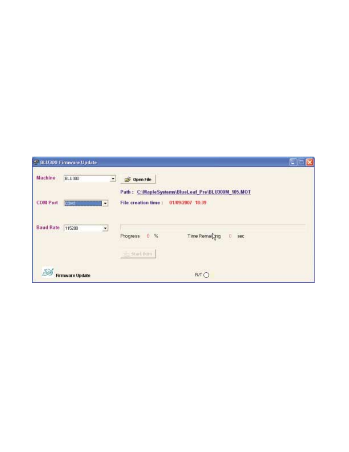
4. Open the BlueLeaf configuration software. From the
BLU300 Firmware Update dialog box appears.
TOOLS menu, select Flash BLU300. The
1010-0300, Rev 02
5. Select Machine (at this time, the only model selectable is BLU300).
6. Select COM Port. This will be the same port used for communication between PC and BLU300.
7. Select Baud Rate.
Page 46

Using BlueLeaf Software 43
8. Open the file that contains the firmware update. Click Open File. The Open File dialog box appears.
Select the file and click Open.
9. The file date and time of creation should appear after selecting the file.
10. Start Firmware Update. Click Start Burn.
11. The progress bar will show file progress. Time Eliminate shows the elapsed tie and the R/T
(Receive/Transit) light will be blinking throughout the burn.
12. When the update is complete, disconnect power from the OIT and disconnect the cable from the
extension port. Reconnect the OIT configuration cable.
1010-0300, Rev 02
Page 47

44 Blue Series Installation & Operation Manual
BLU300 Security
BlueLeaf Software supports the ability to deny or grant access to different objects on screens. Security is achieved by
assigning user levels to each object that needs to be protected.
4 To Configure User Levels/Passwords
1. From the
appears:
TOOLS menu, select User-level/Password set. The User-level/Password set dialog box
2. Click on the
3. Click OK when you are finished configuring all the levels you need.
Level Set drop down menu to select a level and assign a password for that level.
1010-0300, Rev 02
Page 48

Using BlueLeaf Software 45
4 To Assign User/Security Levels
User Levels can be assigned to objects that require operator interface, such as function keys.
1. Start by placing a function key on a screen. From the
place on the screen to place the key (left click mouse to place object.) The Edit Button Object dialog
box appears:
OBJECTS menu, select Function Key. Select a
2. For more details on using the Function Key Object, consult Chapter 9: Using the Function Keys.
3. Click on the
When a security level is assigned, the function key will display a password screen that requires the operator to enter a
password before the predefined action is performed.
User Level drop down menu and select a level. Click OK.
* Security Level applies only to objects on a screen, and not the screen itself. The screen where the
protected objects are displayed is still accessible. To prevent access to a particular screen, use
the Block Key Arrow Paging. Consult Chapter 5 for more details.
1010-0300, Rev 02
Page 49

Basic Operation of the BLU300 47
Chapter 4 - Basic Operation of the BLU300
Overview
The BLU300 operator interface terminal is a graphics-based display with a membrane-style keypad. Below is an outline of
the features of the BLU300:
Front Outline of BLU300
Hardware
Component
Alarm Indicator
ESC (Escape) key
SHIFT key Used to select secondary keys (F6-F10)
F1-F5
1. Flashes if communications to PLC is lost.
2. Can be tagged to PLC register to indicate alarm conditions in control system
Used to cancel any incorrect input. Also used to exit setup menus or cancel
numeric entry input.
Primary keys used to display screens, input numeric values to PLC registers,
or change the state of PLC coils
Description
Up/Down keys:
1. Move through local setup menus
2. Scroll up/down screens
Arrow (Up,
Down, Right,
Left) keys
3. Increase/decrease digit values when using the Numeric Entry screen.
4. Can be configured as function keys
Left/Right keys:
1. Change local setup settings
2. Move to next digit when using the Numeric Entry screen.
3. Can be configured as function keys
ENTER key
1. Accept setup menu selection
2. Accept value entered using the Numeric Entry screen.
1010-0300, Rev 02
Page 50

48 Blue Series Installation & Operation Manual
Using the Left, Right, Top and Down Keys
These keys are normally used only for accessing and maneuvering through the Local Setup menus, and also for entering
numbers in PLC registers. When these keys are not being used for these purposes, they can be configured to behave as
function keys. To configure, use the Button object or Global/Local Function key editors.
Hardware
Component
RS-232/RS422
Power Input
(+24V, 0V, gnd)
RS-485
Battery
Label Model identification label
Extension Port
1. Port used for programming the BLU300
2. Port used to communicate to PLC using RS232
Used to connect +24VDC to BLU300
1. Port used to communicate to PLC using RS485
2. Port used to connect OIT to OIT when transferring projects
Location of CR2032 lithium battery used for internal clock, also
location of DIP switches to select either RS-422 or RS-485 COM.
1. Used for bootcode upgrades
2. Used for uploading/downloading projects with memory stick (PCC)
Description
Local Setup Menus
The Blue Series has local setup menus that are used to configure the OIT and to allow upload/download of project files.
BlueLeaf also has a setup menu that can be configured. The table below provides a brief list of the setup menus and their
function:
1. Read from PC Download project from computer
2. Send to PC Upload project to a computer
3. Copy HMI to HMI Copy a project from one BLU300 to another
4. HMI Setup Modify hardware settings of HMI
1. Com port Change active com port
2. Contrast Set contrast of LCD display
3. Back light Enable a back light saver
4. Date/Time Program the internal clock
5. Buzzer Enable/disable the internal buzzer
6. Language
7. Password Create and enable setup password
8. Start-up display Select user startup screen or predefined screen.
5. Exit & Run Exit setup menus and attempt to communicate to PLC
Select between English, traditional Chinese, simple Chinese
or user-defined.
Accessing the Local Setup Menus
To access the local setup menus, perform one of the following:
•
Power up the BLU300 while holding down the
•
If the BLU300 is communicating to a PLC, hold down the
•
If the BLU300 is attempting to communicate to a PLC but a Timeouterror message is displayed, hold down
the
ESC key for approximately ten seconds.
1010-0300, Rev 02
ESC key for approximately ten seconds.
ESC key for about four seconds.
Page 51

Basic Operation of the BLU300 49
Once the local setup menu is accessed, the following should be displayed on the BLU300:
Downloading a Project to the BLU300
4To download a project to the BLU300, follow these steps:
1. Access the
2. Connect the BLU300 RS-232 port to your computer using the configuration cable (Maple P/N
7431-0102)
3. In BlueLeaf, click Options…PC-HMI Comm Settings to select the PC’s com port and parameters.
4. Compile the project - click Tools…Write Project to BLU300.
5. On the BLU300, press the F1 key or use the up/down arrow keys to move the blinking cursor to
1.Read from PC. Then press the
LOCAL SETUP MENU as shown above.
ENTER key:
5. In BlueLeaf, click the Yes button, to confirm the download. After the file has downloaded, click the
OK button.
6. Press the
7. Disconnect the OIT from the PC and connect the PLC cable to the OIT.
8. Press the F5 key or use the up/down arrow keys to move the blinking cursor to 5.EXIT & RUN, then
press the
The OIT will attempt to communicate to the PLC.
ESC key on the BLU300 to exit the download menu.
ENTER key.
Uploading a Project from the BLU300
4To upload a project from the BLU300, follow these steps:
1. Access the
2. Connect the BLU300 RS-232 port to your computer using the configuration cable (Maple P/N
7431-0102).
LOCAL SETUP MENU per instructions given in the beginning of this chapter.
1010-0300, Rev 02
Page 52

50 Blue Series Installation & Operation Manual
3. In BlueLeaf, click File…Close to close any project that is currently opened.
* If you upload a project from the OIT while an existing project is open, it will overwrite that
project.
4. Click Options…PC-HMI Comm Settings to select the PC’s com port and parameters.
5. On the BLU300, press the F2 key, or use the up/down arrow keys to move the blinking cursor to
2.Send to PC. Press the
ENTER key.
6. In the BlueLeaf software, click Tools…Read Project from BLU300.
7. In BlueLeaf, click the Yes button, to confirm the upload. After the file has been uploaded, click the
OK button.
8. Press the
ESC key on the BLU300 to exit the upload menu.
9. Disconnect the OIT from the PC and connect the PLC cable to the OIT.
10. Press the F5 key or use the up/down arrow keys to move the blinking cursor to 5.EXIT & RUN, then
press the
ENTER key.
11. The OIT will attempt to communicate to the PLC.
Transferring a Project Between Two BLU300s
4To transfer a project from one BLU300 to another, follow these steps:
1. Access the local setup menu per instructions given in the beginning of this chapter.
2. Connect the BLU300 RS-485 port of one OIT to the RS-485 port of the other OIT using
two-conductor twisted pair wire. Connect as shown:
Sending BLU300 (RS-485 Port)
Receiving BLU300 (RS-485 Port)
+ ß ------------------------------------------------------------------- à+
- ß-------------------------------------------------------------------- à-
3. On the BLU300s, press the F4 key, or use the up/down arrow keys to move the blinking cursor to
4.HMI Setup. Press the
4. On 1.Com port, press the
5. On 1.HMI protocol, press the
press the
ENTER key on one of the BLU300s to edit the HMI id number. Use the right/left arrow keys
ENTER key.
ENTER key.
ENTER key. Ensure that the HMI id matches both units. If not,
to move to each digit, then use the up/down arrow keys to change each digit value. When done, press
the
ENTER key to save the changes.
* HMI ID numbers must match exactly or project transfer will not take place. The RS-485 port
parameters do not have to match, the BLU300 units use predefined communications settings
which are not affected by settings in the RS485 menus. Therefore, baud rate, data bits, parity,
and stop bits do not have to match between OITs.
6. Press the
menu.
7. On the BLU300s, press the F3 key, or use the up/down arrow keys to move the blinking cursor to
3.Copy HMI to HMI. Press the
8. On the BLU300 that is to receive the project, use the up/down arrow keys to select 2.Read from
HMI. Then press the
9. On the BLU300 that is to send the project, use the up/down arrow keys to select 1.Send to HMI.
Then press the
10. The BLU300 that is receiving the file should display a message Receiving Project File.
The BLU300 that is sending the file should display a message Sending Project File. When
the downloading sequence has finished, both OITs should display Finished. Press the
clear the message.
11. Press the
12. Transfer is now complete.
ESC key to go back to the HMI SETUP menu. Press ESC key again to go back to the main
ENTER key:
ENTER key.
ENTER key.
ESC key to
ESC key again on both units to exit the transfer menu.
1010-0300, Rev 02
Page 53

Basic Operation of the BLU300 51
HMI Setup Menu for the BLU300
The HMI SETUP menu allows you to change many of the hardware settings of the BLU300 OIT:
* Most of the following settings can be changed through the Tools...HMI default settings. See
page 53 for more information on HMI Default Settings. Adjusting these settings from the local
setup menu is only provided as a convenient method of changing the parameters without
downloading a new project file.
Changing the Com Port Settings
The Com port setting on the OIT allows you to change the OIT’s communications parameters for the RS-232 and RS-485
ports without having to download a new project file from the BlueLeaf configuration software.
* It is not necessary to adjust these settings in the local setup menu, since these settings are
automatically changed whenever you download a project from the BlueLeaf software into the
OIT. Adjusting these settings from the local setup menu is only provided as a convenient method
of changing the parameters without downloading a new project file.
4To change these settings, perform the following:
1. Access the
2. Press the F4 key, or use the up/down arrow keys to move the blinking cursor to 4.HMI Setup.
Press the
3. Use the up/down arrow keys to move the blinking cursor to 1.Com port. Press the
4. There are three menu items:
•
HMI protocol- used to change the OIT’s id #. This id # must match the HMI Comm. Addr setting
found in the BlueLeaf configuration software Options…PC-HMI Comm Settings menu before any
upload/download of a project file can take place. When transferring a project from one OIT to another,
the id #’s must match also.
•
RS232- used to change the communications parameters for the RS-232 port (see table below).
•
RS485- used tochange the communications parameters forthe RS-485/RS-422 port(see table below).
LOCAL SETUP MENU per instructions given in the beginning of this chapter.
ENTER key.
ENTER key.
Parameter Options
Baud Rate 4800, 9600, 19200, 38400, 57600, 115200
Data Bits 8 Bit, 7 Bit
Parity Even, Odd, None
Stop Bit 1 Bit, 2 Bit
5. From the Com port menu, use the up/down arrow keys to move the blinking cursor to the target
selection: HMI protocol, RS-232, RS-485. Press the
6. To change a parameter (such a Baud Rate), use the up/down arrow keys to move the blinking cursor to
the parameter, and then press the
pressing the
ESC key.
ENTER key. At any time, you can cancel changing the parameter by
ENTER key.
1010-0300, Rev 02
Page 54

52 Blue Series Installation & Operation Manual
7. The blinking cursor will highlight the options for the particular parameter you have selected. Use the
right/left arrow keys to select one of the options. Press the
brief message Setup complete will appear, indicating that the new option has been saved.
8. When you have finished modifying parameters, press the
9. Press the
ESC key again to go back to the HMI SETUP menu.
ENTER key to select the new option. A
ESC key to go back to the COM PORT menu.
Changing the Contrast Setting
The contrast setting allows the OIT operator to optimize the contrast for the particular environment the OIT is installed in.
4To change the contrast, perform the following:
1. Access the
2. Press the F4 key, or use the up/down arrow keys to move the blinking cursor to 4.HMI Setup.
Press the
3. Use the up/down arrow keys to move the blinking cursor to 2.Contrast. Then press the
key.
4. From the
contrast will change as you make adjustments.
5. When you have finished modifying the contrast, press the
menu. Press the
Changing the Back light Saver Setting
The backlight can also be controlled by the System Parameter Setting under the Global Settings menu. The backlight save
feature allows the OIT operator to control the LED backlight of the BLU300 LCD display. This feature can be used to
extend the lifespan of the display or minimize the distraction of the OIT when not in use. When configured, the BLU300
will shut off the LED backlight on the OIT display after a predefined time. The backlight is reactivated whenever any key on
the OIT is pressed.
LOCAL SETUP menu per instructions given in the beginning of this chapter.
ENTER key.
ENTER
CONTRAST menu, use the right/left arrow keys to vary the contrast setting of the LCD. The
ENTER key to go back to the HMI Setup
ESC key to cancel any changes.
* The normal function of the key that is pressed will not be executed while the backlight is off.
4To activate the backlight saver using the Local Setup menus:
1. Access the
2. Press the F4 key, or use the up/down arrow keys to move the blinking cursor to 4.HMI Setup.
Press the
3. Use the up/down arrow keys to move the blinking cursor to 3.Back light. Press the
4. From the
function keys to change each digit value (ex. F1 =1, F5 =5, Shift F1 =6, Shift F10 =0). Range is 0 to
99 minutes. Note: if 0 is selected, the back light saver feature is disabled and the back light always
remains on.
5. When you have finished modifying the back light saver, press the
Setup menu. Press the
Controlling the Backlight with the System Parameter Setting
One of the features of the System Parameter Setting is to call up screens on the OIT. The second feature of the System
Parameter Setting is control over the Backlight.
LOCAL SETUP MENU per instructions given in the beginning of this chapter.
ENTER key.
ENTER key.
BACK LIGHT menu, use the right/left arrow keys to switch between the two digits. Use the
ENTER key to go back to the HMI
ESC key to cancel any changes.
1010-0300, Rev 02
Page 55

Basic Operation of the BLU300 53
4To configure the System Parameter Setting for Backlight control:
1. From the Global Settings menu, select System Parameter Setting. The System Parameter Editor dialog
box appears:
2. In the PLC/Controller Address frame, enter the PLC register address, or click the PLC/Controller
Address button to display the address dialog box.
3. Click the pull-down box to select the target PLC memory area. Use the numeric keypad to enter the
specific PLC memory address. Select the PLC Network Address (if applicable) and (HMI
communications port. Click Enter to go back to prior dialog box.
4. Click Set to enable to System Parameter Setting, Cancel Set to disable the System Parameter Setting,
or Close to exit the System Parameter Editor window and return to the work area.
The OIT will now monitor that address. If the PLC writes a value (16-bit Signed) into this register, the OIT will attempt to
display the screen (Consult Chapter 5 - Creating and Displaying Screens, Displaying screens using the System Parameter
Setting for more information.) The next consecutive address will control the backlight. If the next consecutive register has a
value of 1 for Bit 0, the backlight will always be on, regardless of the backlight setting set in the Local Setup Menu of the
OIT or the HMI Default Settings. If Bit 0 is 0, the OIT will shut off the backlight according to the setting set with the Local
Setup Menu of the OIT or the HMI Default Settings.
Setting the Internal Clock
The Date/Time setting allows the OIT’s internal clock to be set.
4To change the clock, perform the following:
1. Access the
2. Press the F4 key, or use the up/down arrow keys to move the blinking cursor to 4.HMI Setup.
Press the
3. Use the up/down arrow keys to move the blinking cursor to 4.Date/Time. Press the
4. From the Date/Time menu, use the up/down arrow keys to move the blinking cursor to the parameter
you wish to change (ex. Date, Week, etc).
LOCAL SETUP MENU per instructions given in the beginning of this chapter.
ENTER key.
ENTER key.
1010-0300, Rev 02
Page 56

54 Blue Series Installation & Operation Manual
5. Press the ENTER key. The blinking cursor will now highlight the options for that parameter.
6. Use the right/left arrow keys to switch between the options or digits for that parameter. Use the
function keys to change each digit value (ex. F1 =1, F5 =5, Shift F1 =6, Shift F10 =0).
7. When you have finished modifying the clock settings, press the
Setup menu. Press the
ESC key to cancel any changes.
ENTER key to go back to the HMI
* The Date/Time setting menu also displays a bar graph which represents the relative amount of
energy left in the clock battery.
4 To adjust date/time using BlueLeaf software
1. From the TOOLS menu, click HMI Default Settings. The HMI Default Setting dialog box appears.
2. In the Functional Settings frame, check the Download PC Time box.
3. Click OK. Then download the project to the OIT. The BlueLeaf software will update the internal
clock of the BLU300 according to the time/date set in the PC.
Enabling/Disabling the Internal Buzzer
The Buzzer setting allows the OIT’s internal buzzer to be disabled or enabled.
4 To change the Buzzer, perform the following:
1. Access the
2. Press the F4, key or use the up/down arrow keys to move the blinking cursor to 4.HMI Setup.
Then press the
3. Use the up/down arrow keys to move the blinking cursor to 5.Buzzer. Press the
4. From the
Silent.
5. Press the
cancel any changes .
LOCAL SETUP MENU per instructions given in the beginning of this chapter.
ENTER key.
BUZZER menu, use the up/down arrow keys to move the blinking cursor to 1.Normal or 2.
ENTER key to save the change and go back to the HMI Setup menu. Press the ESC key to
ENTER key.
1010-0300, Rev 02
Page 57

Basic Operation of the BLU300 55
4 To enable/disable buzzer using BlueLeaf software
1. From the TOOLS menu, click HMI Default Settings. The HMI Default Setting dialog box appears.
2. In the Functional Settings frame, check the Enable Buzzer Setting box.
3. Click OK. Then download project to the OIT.
Setting the Menu Language
The BLU300 Local Setup menus and the BlueLeaf configuration software can be configured in English, Simplified Chinese
or Traditional Chinese.
4 To select language using the Local Setup menus:
1. Access the
2. Press the F4 key, or use the up/down arrow keys to move the blinking cursor to 4. HMI Setup, Press
the ENTER key.
3. Use the up/down arrow keys to move the blinking cursor to 6. Language. Press the Enter key.
4. From the Language menu, use te up/down arrow keys to highlight 1.English or 2.Trad. Chinese or
3.Simp. Chinese.
5. Press the ENTER key to save the change and go back to the HMI Setup menu. Press the ESC key to
cancel any changes.
LOCAL SETUP MENU per instructions given in the beginning of this chapter.
* This only changes the language used in the Local Setup menus, not the project in the unit.
Setting the Local Setup Password
The Password setting allows you to restrict access to the LOCAL SETUP menus.
4To change the password, perform the following:
1. Access the
2. Press the F4, key or use the up/down arrow keys to move the blinking cursor to 4.HMI Setup.
Press the
3. Use the up/down arrow keys to move the blinking cursor to 7.Password. Press Enter
4. From the PASSWORD menu, use the up/down arrow keys to move the blinking cursor to the parameter
you wish to change: 1. New password or 2.Enable.
5. Press the
current 4-digit password. The blinking cursor will now highlight the first digit of the password.
6. Use the right/left arrow keys to switch between the digits of the password, and then use the function
keys to change each digit value. The password can be any set of four digits and/or characters. To
enter digits or characters, each function key has assigned a set of password characters as follows:
LOCAL SETUP MENU per instructions given in the beginning of this chapter.
ENTER key.
.
ENTER key on 1.New password. The Password Entry screen appears, showing the
F1:
16ABCDEF
1010-0300, Rev 02
Page 58

56 Blue Series Installation & Operation Manual
F2:
27GHIJK
F3:
38LMNOP
F4:
49QRSTU
F5:
50VWXYZ
Scroll through each list of characters for each function key by continuously pressing that key.
7. When you have finished setting the new password, press the
the
ESC key to cancel any changes. A message will appear indicating that the new password has been
saved. Press the
8. Use the up/down arrow keys to move to 2.Enable. Press the
from No to Yes.
9. When you have finished setting the new password, press the
menu.
ESC key to go back to the Password menu.
ENTER key to save the password. Press
ENTER key to alternate the setting
ESC key to go back to the HMI SETUP
* If you forget the password, you can still access the LOCAL SETUP menus by entering the backdoor
password ‘8888’. However, once this backdoor password is entered, the BLU300 will clear the
prior password and the project stored in the OIT. The OIT will be reset to factory settings and
must be reprogrammed.
4 To enable the Local Setup Password using BlueLeaf software
1. From the Tools menu, click HMI Default Settings. The HMI Default Settings Dialog box appears.
2. In the Password setting frame, check the Enable Password Setting box and enter the four digit
password in the entry box.
3. Click OK.
Using the Local Setup Password
During operation, if access to the Local Setup menus is attempted, the BLU300M will display a Password Entry screen. Use
the function keys to enter the four digit password. After each digit is entered, use the Right/Left arrow keys to move to the
next digit. When the password has been entered, press the Enter key to accept the password or the ESC key to exit without
entering a password.
If the password is correct, then access to the Local Setup menus is given. If the password is incorrect, an error message is
displayed on the OIT and the operator is given another opportunity to enter the correct password.
1010-0300, Rev 02
Page 59

Basic Operation of the BLU300 57
Selecting the Startup Display
The Startup Display setting allows you to enable or disable the herald screen as seen below:
When enabled, this screen briefly appears whenever the OIT is powered up. Then the first screen of your project is
displayed.
4To change the Startup Display, perform the following:
1. Access the
2. Press the F4 key, or use the up/down arrow keys to move the blinking cursor to 4.HMI Setup.
Press the
3. Use the up/down arrow keys to move the blinking cursor to 8.Start-up display. Press the
ENTER key.
4. From the
Default or 2. User Defined.
5. Press the
cancel any changes.
LOCAL SETUP MENU per instructions given in the beginning of this chapter.
ENTER key.
START-UP DISPLAY menu, use the up/down arrow keys to move the blinking cursor to 1.HMI
ENTER key to save the change and go back to the HMI SETUP menu. Press the ESC key to
HMI Configuration Settings
The BlueLeaf software has several configurable settings that can be set and will download to the OIT every time a project is
downloaded. Some of the settings that can be changed in the OIT Local Setup menu can be configured here.
1010-0300, Rev 02
Page 60

58 Blue Series Installation & Operation Manual
4 To configure the HMI default settings
1. On the TOOLS menu, click HMI Default Settings. The HMI Default Setting dialog appears.
2. In the Select Default COM Port area, select either COM1 (RS232) for RS232 communication or COM2
(RS485/RS422) for RS485/RS422 communication.
3. In the Set Default PLC Network Address area, enter, or use the up/down arrows, to select a Network
Address, if applicable (default is 1).
4. In the Contrast Setting area, move the slider to the desired pixel contrast (default is 8).
5. In the Backlight Setting area, enter, or use the up/down arrows, to select backlight time 0-99 minutes
(default is 0).
6. In the Functional Settings area:
a. Check the box next to Enable Buzzer Setting to enable the buzzer to sound with each keypress.
b. Check the box next to Download PC Time to update the OIT with the PC's time
c. Check the box next to Enable Password Setting to enable a four digit setup password. After
enabling, enter a four-digit password in the space provided.
d. In the Start-Up Display area, select either HMI Default or User-Defined. User Defined enables the
Herald Screen at start-up.
7. Click OK to accept changes or Cancel to cancel any changes made.
1010-0300, Rev 02
Page 61

Basic Operation of the BLU300 59
4 To configure HMI-PLC Communication Settings
1. On the TOOLS menu, click HMI-PLC Comm. Settings. The HMI-PLC Communications Settings
dialog appears.
2. In the Baud Rate area, use the drop down menu to select 115200, 57600, 38400, 19200, 9600 or 4800
bps.
3. In the Data bits area, use the drop down menu to select either 8 or 7 bits.
4. In the Parity area, use the drop down menu tot select Even, Odd,orNone.
5. In the Stop bit area, use the drop down menu to select either 1 or 2 bit.
6. Click Enter to accept changes or Cancel to cancel any changes made.
Auto Save Options
The AutoSave Options can be used to automatically save the project whenever the Compile feature is used or a preset timed
interval.
4 To configure AutoSave Options
1. On the TOOLS menu, click AutoSave Options. The AutoSave Options dialog box will appear:
2. Check the box next to Enable Automatic Save to enable the AutoSave Option.
a. Choose Before compiling to save the project whenever the project is compiled.
1010-0300, Rev 02
Page 62

60 Blue Series Installation & Operation Manual
b. Choose Timed Interval, then enter, or use the up/down arrow keys, to select an interval from
1-200 minutes that will save the project at that interval.
3. Click OK to accept changes or Cancel to cancel any changes made.
System Clock Setting
The System Clock Setting is used to write the time and date of the OIT to a register in the PLC/Controller.
4 To configure the System Clock Setting
1. On the Global Settings menu, click System Clock Setting. The System Clock Setting dialog box will
appear.
2. In the PLC/Controller Address frame, enter the PLC register address, or click the PLC/Controller
Address button to display the address dialog box:
3. Click the pull-down box to select the target PLC memory area. Use the numeric keypad to enter the
specific PLC memory address. Select the PLC Network Address (if applicable) and HMI
communications port. Click Enter to go back to prior dialog box.
4. Click Set to accept changes, Close to cancel any changes made, or Cancel Set to cancel a previously
set System Clock Setting.
* The time/date will be written to the OIT in the following format (Dn is the first register
-Dn Year (example: 20077 is displayed as "7"
-Dn+1 Day (Monday = 1, Tuesday = 2, Wednesday = 3, etc.)
-Dn+3 Month (example: May is displayed as "8")
-Dn+4 Hours (24 hour clock)
-Dn+5 Minutes
-Dn+6 Seconds
Power On Macro Setting
The Power On Macro Setting is used to Write a constant to a PLC/Controller register or to set/reset a coil in the
PLC/Controller.
1010-0300, Rev 02
Page 63

Basic Operation of the BLU300 61
4 To configure the Power On Macro Setting
1. On the GLOBAL SETTINGS menu click Power on Macro Setting. The Power On Macro Setting
dialog appears.
2. In the PLC/Controller Address area, select either bit for coils, or value for registers.
3. In the PLC/Controller Address frame, enter the PLC register address, or click the PLC/Controller
address button to display the address dialog box.
4. Click the pull-down box to select the target PLC memory area. Use the numeric keypad to enter the
specific PLC memory address. Select the PLC Network Address (if applicable) and enter the specific
HMI communications port. Click Enter to go back to prior dialog box.
5. If bit was selected in the PLC/Controller Address area, in the Bit Setting area, select either ON to set
the bit/coil or OFF to reset the bit/coil.
6. If the value was selected in the PLC/Controller Address area, in the Value Display Setting area, select
the Format Unsigned, Signed, Hexadecimal,orBCD from the Format drop down menu; and the Size
16 or 32 bits from the Size drop down menu; and enter the value of the constant to be written to the
register in the Set Value frame.
7. In the time Interval area, select the time 500, 1000, 1500,or2000 ms from the drop down menu.
8. Click Set to accept changes, Close to cancel any changes made, or Cancel Set to cancel a previously
set Power On Macro Setting.
1010-0300, Rev 02
Page 64

62 Blue Series Installation & Operation Manual
1010-0300, Rev 02
Page 65

Creating and Displaying Screens 63
Chapter 5- Creating and Displaying Screens
This section shows how to create screens using BlueLeaf software. To better illustrate some of the examples, please open the
sample project (BLU300M.MPL) included with the BlueLeaf configuration software.
Creating Screens
An operator interface terminal wouldn’t be very useful if all of the information to be displayed could only be placed onto one
screen. Therefore, most OITs have multiple screens that can be used to display information. The Maple Systems Blue Series
is capable of storing up to 999 screens (actual limit is determined by memory requirements of each screen), giving you
maximum flexibility in designing your operator interface.
This chapter will demonstrate how to create new screens, create a Herald Screen, use the Screen Manager, and how to
display screens using the OIT or the PLC to call up screens, and how to write a screen number to the PLC.
Opening a Screen
To view the contents of a screen in BlueLeaf, it must first be opened. When you create or open an existing project file only
the initial screen (Screen 0) is opened. To view any other screens that have already been created, you must first open the
screen. This can be done using the Screen Manager:
1010-0300, Rev 02
Page 66

64 Blue Series Installation & Operation Manual
4To open a screen
1. From the
Toolbar. The Screen Manager dialog box appears:
TOOLS menu, select Screen Manager. Or click the Screen Manager icon from the Standard
1010-0300, Rev 02
2. Click on the screen you wish to open, and then click OK. You can also open the screen by
double-clicking it.
3. The Screen Manager dialog box closes and the opened screen is displayed in the BlueLeaf work area.
Double clicking the screen name will open the screen but will not close the screen manager dialog.
Page 67

Creating and Displaying Screens 65
Let’s look at the Screen Manager again, using the sample project.
The Screen Manager lists all of the screens currently created for the project. You will notice that in the sample project, ten
screens have been created. Each screen is listed with a screen number and title. The screen title is the name that you assign
to the screen in the Screen Manager. Finally, you will notice that the Screen Manager can also be used to create a new
screen, open all screens at once, or delete a screen.
* When you delete a screen, the Screen Manager will automatically renumber all of the screens
above that screen, to fill in the missing screen. For example, if Screen #8 is deleted, Screen #9
will be renamed as Screen #8. In some cases, this may present a problem with your application.
If so, simply Insert a new blank screen to replace the deleted screen.
Press the Close command button to return to the main BlueLeaf screen.
By default, when a screen is opened it will become active in the work area of BlueLeaf. Other open screens will be moved to
the background. To switch between open screens, open the Screen Manager and select from the list of screens currently
open. You can also cascade or tile the open screens to see the screens through the windows menu at the same time. Finally,
you can use the previous page or next page buttons on the Standard Toolbar to scroll through the open
screens.
BlueLeaf requires more resources from your computer every time you open another screen. When many screens are open,
the performance of the computer may be affected; therefore, you may wish to close some of the screens until you are ready to
edit them.
1010-0300, Rev 02
Page 68

66 Blue Series Installation & Operation Manual
4To close a screen
You will notice three small icons located in the upper right hand corner of each screen: the minimize icon , the
maximize icon , and the close icon . To close a screen, click the close icon associated with that screen.
Creating a New Screen
Whenever you create a new project file, only the initial screen (Screen 0) is automatically created. To create any other
screens, you must complete the following steps.
4 To create a new screen
From the
through the screen manager function. The BlueLeaf software will create a new screen and display it in the work area:
EDIT menu, select Add New Screen or click on the New Screen icon in the Standard toolbar, or add a screen
If you wish to assign a screen title to the screen you just created, click on the Screen Manager, click on the new screen and
enter a new title under Screen Title.
1010-0300, Rev 02
Page 69

Creating and Displaying Screens 67
Deleting a Screen
4To delete a screen
1. From the
Toolbar. The Screen Manager dialog box appears.
2. Highlight the screen that you wish to delete.
3. Click the Delete command. A dialog box appears asking if you want to delete this screen.
4. Click Yes. The dialog box disappears and the selected screen is deleted.
5. Click Close in the Screen Manager to go back to the BlueLeaf main screen.
Creating a Herald Screen
The BlueLeaf configuration software allows the creation of a "herald" screen for the BLU30. This is a screen that can
display text and/or bitmap images. This screen can be used to display a common logo or useful information. The herald
screen is displayed briefly every time the power is applied to the OIT.
Configuring the Herald Screen
4 To create the herald screen
1. From the Global Settings menu, select Herald Screen. This will display a new screen with the title
Herald Screen in the work area.
TOOLS menu, select Screen Manager. Or click the Screen Manager icon from the Standard
2. Text objects may be used to display text or bitmap objects may be used to display bitmaps. Drawing
tools may also be used to create shapes on this screen.
4 To download the herald screen
1. Apply power to the OIT while holding down the ESC key.
2. Continue holding down the ESC key until the Local Setup menus appear on the OIT screen.
3. On the OIT, press the F1 key to select 1. Read from PC.
4. From the TOOLS menu of BlueLeaf, click Write Herald Screen to BLU300. The Confirm dialog
box appears.
5. On the OIT, press the ENTER key to receive a download file.
6. Click Yes in the BlueLeaf dialog box to begin the download.
7. When the download is complete, click OK.
4 To display the herald screen on the OIT
1. Access the Local Setup menu as described previously in this chapter.
2. On the OIT, press F4, or use the up/down arrow keys to move the linking cursor to 4. HMI Setup.
Press the ENTER key.
1010-0300, Rev 02
Page 70

68 Blue Series Installation & Operation Manual
3. Use the up/down arrow keys to move the blinking cursor to 8. Start-up display. Press the ENTER
key.
4. From the START-UP DISPLAY menu, use the up/down arrow keys to move the blinking cursor to 1.
HMI Default or 2. User Defined.
5. Press the ENTER key to save the change and go back to the HMI SETUP menu. Press the ESC key to
cancel any changes.
6. Now when power is cycled/applied to the OIT, the Herald Screen will display.
Writing the Screen Number to a PLC Register
There may be occasions in which a particular screen is displayed using a Function Key on the BLU300 and you wish the
PLC to know that the screen has been displayed. Or, you may configure the PLC to display a screen on the BLU300 using
the "Jump To Screen" feature, and would like confirmation that the screen has been displayed. This feature allows
configuration of the BLU300 to write the screen number of the screen displayed to a PLC register.
4 To Write a screen number to a PLC using the Local Screen Settings
1. Open the screen whose number is to be written to the PLC.
2. From the Local Screen Settings menu, select Write Screen# to PLC. The Write Screen# to PLC
dialog is displayed.
3. In the PLC/Controller Address frame, enter the PLC/register address, or click he PLC/Controller
Address button to display the address dialog.
4. Click the pull-down box to select the target PLC memory area. Use the numeric keypad to enter the
specific PLC memory address. Select the PLC Network Address (if applicable) and HMI
communications port. Click Enter to go back to prior dialog box.
5. Click Set to accept changes, Close to cancel any changes made, or Cancel Set to cancel a previously
set Write Screen# to PLC Setting.
The OIT will now write the value of the screen number that is being displayed to the corresponding PLC/Controller address
specified above.
1010-0300, Rev 02
Page 71

Creating and Displaying Screens 69
How to Display Screens
Screens are displayed on the BLU300 using the following methods:
Configuring the OIT to continuously monitor a PLC register or coil using the ‘Jump To Screen’ feature
•
Configuring a function key to display a new screen
•
Use the up/down arrow keys to scroll through the screens
•
Using the System Parameter Setting in the Global Settings menu
•
Jump to Screen Feature
The ‘Jump To Screen’ feature is used to configure a PLC coil or register that the OIT will continuously monitor for a
condition. If that condition is met, then the OIT will display the assigned screen. There are two ‘Jump To Screen’ editors:
the Local and Global editors. The Global Jump To Screen feature is used to configure a PLC coil/register that will be
monitored by the OIT regardless of which screen is currently being displayed. The Local Jump To Screen feature is used to
configure a PLC coil/register that will only be monitored by the OIT when that screen is displayed.
4To create a ‘Jump To Screen’ object
1. To use the global object, from the
object, click the
Settings dialog box appears:
LOCAL SCREEN SETTINGS menu, then Jump To Screen. The Jump To Screen
GLOBAL SETTINGS menu, select Jump To Screen. To use the local
2. Click on the type of PLC memory you wish to use under Screen Condition: Bit or Value (16 or 32
Bits).
1010-0300, Rev 02
Page 72

70 Blue Series Installation & Operation Manual
3. In the PLC/Controller Address frame, enter the PLC coil or register address. Or click the
PLC/Controller Address button to display the Edit PLC/Controller Address dialog box:
4. In the reference address area, click the pull-down box to select the target PLC memory area. Use the
numeric keypad to enter the specific PLC memory address. Select the PLC Network Address (if
applicable) and HMI communications port. Click Enter to go back to prior dialog box.
5. Use the Jump Screen pull-down box to select the screen you want to display if the trigger condition is
met.
6. For Bit Only- Select Device OFF if the screen must appear when the PLC coil is off. Select Device
ON if the screen appears when the PLC coil is on.
7. For Value Only- In the Size: box, use the pull-down box to select 16 bit or 32 bit register.
8. For Value Only- Use the Format: pull-down box to select the format that determines how the OIT
reads the value in the PLC register. Select from:
Format Range
Unsigned
Signed
Hexadecimal
BCD
0 to 65535 16 unsigned 16 bit format
0 to 4294967295 32 unsigned 32 bit format
-32768 to +32767 16 signed 16 bit format
-2147483648 to
+2147483647
0000 to FFFF 16 hexadecimal 16 bit format
00000000 to FFFFFFFF 32 hexadecimal 32 bit format
0000 to 9999 16 BCD 16 bit format
00000000 to 99999999 32 BCD 32 bit format
Size
(Bits)
32 signed 32 bit format
Description
9. For Value Only- In the Trigger Condition box, enter the Device Value that will be used to compare
with the value actually in the PLC register.
10. For Value Only- In the Trigger Condition box, use the pull-down box to select the mathematical
expression that will be used to compare the entered constant value with the value read from the PLC
register: For example, suppose the PLC register is 4x1 and the Device Value used is 5.
Trigger
Condition
= Equal condition
Description Example
4x1 = 5: if value in register 4x1 is equal to
5, activate
screen.
1010-0300, Rev 02
Page 73

Creating and Displaying Screens 71
> Greater than condition
< Less than condition
>= Greater than or equal to
<= Less than or equal to
!= Not equal
11. Click the Add In button to add the condition to the list. You can have multiple trigger conditions
assigned.
12. If you need to make a change to a trigger condition on the list, simply click on the trigger condition to
highlight, and then make the necessary modifications in the edit fields. Click the Update button.
13. If you decide to delete one of the trigger conditions, highlight the trigger condition on the list and click
the Delete button.
14. When you have finished editing the trigger conditions for the ‘Jump To Screen’ object, click the Close
button.
15. The Jump To Screen Settings dialog box closes and the active screen is displayed in the BlueLeaf
work area.
Displaying screens using function keys
4x1 > 5: if value in register 4x1 is greater
than 5, activate
4x1 < 5: if value in register 4x1 is smaller
than 5, activate
4x1 >= 5: if value in register 4x1 is greater
than or equal to 5, activate
4x1 <= 5: if value in register 4x1 is less than
or equal to 5, activate
4x1 != 5: if value in register 4x1 is not 5,
activate
screen.
screen.
screen
screen
screen.
Function keys are also used to display a screen. As with the ‘Jump To Screen’ feature, there are two Function Key editors:
the Local and Global editors. The Global Function Key Editor is used to configure a function key that, when pressed, will
display a screen on the OIT regardless of which screen is currently being displayed. The Local Function Key Editor is used
to configure a function key that, when pressed, will only switch to the target screen if the screen that the local function key
was created on is displayed. For more information on configuring a local or global function key to display a screen, consult
Chapter 9- Using The Function Keys.
Displaying screens using the up/down arrow keys
The Up and Down Arrow keys of the BLU300 are used to scroll through the screens. Pressing the Down Arrow key causes
the OIT to ‘page down’ to the next screen. For example, if Screen #5 is currently displayed on the OIT, pressing the Down
Arrow key causes Screen #6 to appear.
The Up Arrow key is used to ‘page up’ to the prior screen. If Screen #5 is currently displayed on the OIT, then pressing the
Up Arrow key causes Screen #4 to appear.
There may be some situations in which you do not want a screen to be accessible using the up/down arrow keys:
•
A screen is configured that should only be displayed by a request from the PLC (i.e. an alarm)
•
A screen needs to be protected against unauthorized access, so you configure a function key to display a
screen with password-protection
•
You want some screens to be ‘chained’ together but not all screens
If you have a screen that you do not want accessible using the up/down arrow keys, do the following:
4Block Key Arrow Paging
1. Open the screen that you wish to isolate from the paging feature of the up/down arrow keys.
2. From the
next to the Block Key Arrow Paging to indicate that it is enabled. To disable this feature, click again.
3. When the up/down arrow keys are used to page through screens, this screen will be skipped.
LOCAL SCREEN SETTINGS menu, select Block Key Arrow Paging. A checkmark is placed
Displaying Screens Using the System Parameter Setting
The System Parameter Editor feature can be used to configure a PLC register that the OIT will continuously monitor for a
value. If that value corresponds to a screen number within the OIT, then the OIT will display that screen.
1010-0300, Rev 02
Page 74

72 Blue Series Installation & Operation Manual
4 To configure the System Parameter Setting to display a screen
1. From the Global Settings menu, select System Parameter Setting. The System Parameter Editor
dialog appears.
2. In the PLC/Controller Address frame, enter the PLC/register address, or click the PLC/Controller
Address button to display the address dialog.
3. Click the pull-down box to select the target PLC memory area. Use the numeric keypad to enter the
specific PLC memory address. Select the PLC Network Address (if applicable) and HMI
communications port. Click Enter to go back to prior dialog box.
4. Click Set to enable the System Parameter Setting, Cancel Set to disable the System Parameter Setting,
or Close to exit the System Parameter Editor window and return to the work area.
The OIT will now monitor that address. If the PLC writes a value (16-bit Signed) into this register, the OIT will attempt to
display the screen. If the screen does not exist, the OIT will continue to display the existing screen. If a new screen is
displayed, the OIT will write a value of -1 into the register after it has displayed the new screen.
* If this feature is enabled, the "Jump to Screen" feature will no longer be available.
1010-0300, Rev 02
Page 75

Creating Graphic Objects 73
Chapter 6 - Creating Graphics Objects
Drawing Objects
To display any graphic objects on the OIT screen, you must either create them using the drawing tools included with
BlueLeaf software, import them as bitmaps from another applications program, or select from the many choices available in
the graphic libraries included with BlueLeaf software.
This chapter shows you how to create, use, and save graphics objects in BlueLeaf software. You have learned from previous
chapters how graphics objects are placed onto windows. In this chapter, we concentrate on how to create graphics objects.
Using the Drawing Tools
Several drawing tools are provided in BlueLeaf software that make it easy to create graphic objects. With these tools, you
can create simple geometric shapes such as straight lines, circles, rectangles, and polygonal shapes. You can also combine
various geometric shapes to form complex shapes.
Line Thickness for Outlines
For most of the drawing objects below, it is possible to select the thickness and type of outline. To select line thickness, prior
to selecting the drawing tool, select one of the following line type/thickness tools from the toolbar:
Depending on which you select, the selected shape will be drawn with an outline that is of that thickness or a dotted line
outline.
The Line Tool
Use the Line tool to create straight lines on a window screen. Each line that you create has two parameters associated with it:
length and thickness.
4To create a line
1. From the
2. Move the mouse cursor over to the work area of BlueLeaf software onto the screen that you are
currently editing. The mouse cursor changes to a crosshair cursor. Click and drag on the screen to
mark the beginning of the line.
3. While holding the left button on the mouse, drag the black outline box to the point where you wish to
mark the end of the line. Release the left button of the mouse to display the new line. A series of small
white square blocks will appear around the boundaries of the line.
4. Click and drag on the small white boxes (the mouse cursor will change to a double arrow) to change
direction or size of the line.
5. Click and drag anywhere within the border of the new line to move it to a new location.
6. Modify the line thickness by highlighting the line (clicking on it) and then selecting one of the four
options in the Draw toolbar.
7. To continue creating more lines, move the crosshair cursor to a new location and repeat. To
discontinue creating new lines, click on the mouse cursor icon in the Objects toolbar or click on any
object on the screen.
The Rectangle Tools
The rectangle tools are used to create rectangles or squares. The Rectangle (outline) tool creates a rectangle. The Rectangle
(solid) tool creates a solid rectangle.
DRAW menu, click Line or click the Line icon in the Draw toolbar.
4To create a rectangle or
1. From the
toolbar.
2. Move the mouse cursor over to the work area of BlueLeaf software onto the screen that you are
currently editing. The mouse cursor changes to a crosshair cursor. Click and drag on the screen to
mark the beginning of the rectangle.
DRAW menu, click Rectangle (outline or solid) or click the Rectangle icon in the Draw
1010-0300, Rev 02
Page 76

74 Blue Series Installation & Operation Manual
3. While holding the left button on the mouse, drag the black outline box to the point where you wish to
mark the opposite end of the rectangle. Release the left button of the mouse to display the new
rectangle. A series of small white square blocks will appear around the boundaries of the rectangle.
4. Click and drag on the small white boxes (the mouse cursor will change to a double arrow) to change
the width or height of the rectangle.
5. Click and drag anywhere within the border of the new rectangle to move it to a new location.
6. Modify the rectangle (outline) thickness by highlighting the rectangle (clicking on it) and then
selecting one of the four options in the Draw toolbar.
7. To continue creating more rectangles, move the crosshair cursor to a new location and repeat. To
discontinue creating new rectangles, click on the mouse cursor icon in the Objects toolbar or click on
any object on the screen.
The Circle Tools
The circle tools are used to create ellipses or circles. The Circle (outline) tool creates a circle. The Circle (solid) tool creates
a solid circle.
4To create a circle or
1. From the
2. Move the mouse cursor over to the work area of BlueLeaf software onto the screen that you are
currently editing. The mouse cursor changes to a crosshair cursor. Click and drag on the screen to
mark the beginning of the circle.
3. While holding the left button on the mouse, drag the black outline box to the point where you wish to
mark the opposite end of the circle. Release the left button of the mouse to display the new circle. A
series of small white square blocks will appear around the boundaries of the circle.
4. Click and drag on the small white boxes (the mouse cursor will change to a double arrow) to change
the width or height of the circle.
5. Click and drag anywhere within the border of the new circle to move it to a new location.
6. Modify the circle (outline) thickness by highlighting the circle (clicking on it) and then selecting one
of the four options in the Draw toolbar.
7. To continue creating more circles, move the crosshair cursor to a new location and repeat. To
discontinue creating new circles, click on the mouse cursor icon in the Objects toolbar or click on any
object on the screen.
DRAW menu, click Circle (outline or solid) or click the Circle icon in the Draw toolbar.
The Curve Tool
The curve tool is used to create curves. Each curve created has three parameters associated with it: size, thickness, and
orientation.
4To create a curve
1. From the
2. Move the mouse cursor over to the work area of BlueLeaf software onto the screen that you are
currently editing. The mouse cursor changes to a crosshair cursor. Click and drag on the screen to
mark the beginning of the curve.
3. While holding the left button on the mouse, drag the black outline box to the point where you wish to
mark the opposite end of the curve. Release the left button of the mouse to display the new curve. A
series of small white square blocks will appear around the boundaries of the curve.
4. Note: Once the curve has been placed onto the screen, it is not possible to change the orientation (how
the curve bends- right, left, upward or downward) of the curve. Therefore, in order to place the curve
onto the screen with a correct orientation, you must select the proper corner when initially placing the
curve onto the screen:
DRAW menu, click Curve or click the Curve icon in the Draw toolbar.
1010-0300, Rev 02
For start at the upper left corner
Page 77

Creating Graphic Objects 75
For start at the lower left corner
For start at the upper right corner
For start at the lower right corner
5. Click and drag on the small white boxes (the mouse cursor will change to a double arrow) to change
the width or height of the curve.
6. Click and drag anywhere within the border of the new curve to move it to a new location.
7. Modify the curve (outline) thickness by highlighting the curve (clicking on it) and then selecting one
of the four options in the Draw toolbar.
8. To continue creating more curves, move the crosshair cursor to a new location and repeat. To
discontinue creating new curves, click on the mouse cursor icon in the Objects toolbar or click on any
object on the screen.
The Chord Tools
The chord tools are used to create chords. The Chord (outline) tool creates a chord. The Chord (solid) tool creates a solid
chord.
4 To create a chord or
1. From the
2. Move the mouse cursor over to the work area of BlueLeaf software onto the screen that you are
currently editing. The mouse cursor changes to a crosshair cursor. Click and drag on the screen to
mark the beginning of the chord.
3. While holding the left button on the mouse, drag the black outline box to the point where you wish to
mark the opposite end of the chord. Release the left button of the mouse to display the new chord. A
series of small white square blocks will appear around the boundaries of the chord.
4. Note: Once the chord has been placed onto the screen, it is not possible to change the orientation (how
the chord bends- right, left, upward or downward) of the curve. Therefore, in order to place the chord
onto the screen with a correct orientation, you must select the proper corner when initially placing the
chord onto the screen:
DRAW menu, click Chord (outline or solid) or click the Chord icon in the Draw toolbar.
For start at the upper left corner
For start at the lower left corner
For start at the upper right corner
1010-0300, Rev 02
Page 78

76 Blue Series Installation & Operation Manual
For start at the lower right corner
5. Click and drag on the small white boxes (the mouse cursor will change to a double arrow) to change
the width or height of the chord.
6. Click and drag anywhere within the border of the new chord to move it to a new location.
7. Modify the chord (outline) thickness by highlighting the chord (clicking on it) and then selecting one
of the four options in the Draw toolbar.
8. To continue creating more chords, move the crosshair cursor to a new location and repeat. To
discontinue creating new chords, click on the mouse cursor icon in the Objects toolbar or click on any
object on the screen.
The Sector Tools
The sector tools are used to create sectors of circles. The Sector (outline) tool creates a sector. The Sector (solid) tool
creates a solid sector.
4To create a sector or
1. From the
2. Move the mouse cursor over to the work area of BlueLeaf software onto the screen that you are
currently editing. The mouse cursor changes to a crosshair cursor. Click and drag on the screen to
mark the beginning of the sector.
3. While holding the left button on the mouse, drag the black outline box to the point where you wish to
mark the opposite end of the sector. Release the left button of the mouse to display the new sector. A
series of small white square blocks will appear around the boundaries of the sector.
4. Note: Once the sector has been placed onto the screen, it is not possible to change the orientation (how
the sector points- right, left, upward or downward) of the sector. Therefore, in order to place the sector
onto the screen with a correct orientation, you must select the proper corner when initially placing the
sector onto the screen:
DRAW menu, click Sector (outline or solid) or click the Sector icon in the Draw toolbar.
For start from the upper left corner
For start from the lower left corner
For start at the upper right corner
For start at the lower right corner
The Polygon Tool
The polygon tool is used to create irregular shapes with many sides.
4To create a polygon
1. From the
2. Move the mouse cursor over to the work area of BlueLeaf software onto the screen that you are
currently editing. The mouse cursor changes to a crosshair cursor. Click on the screen to mark the
beginning of the polygon.
3. Move the cursor to a new location and click. A line is created. Move the cursor to another location
and click. Another side is created.
4. Continue moving the cursor to each vertex of the polygon you want to create until finished.
DRAW menu, click Polygon or click the Polygon icon in the Draw toolbar.
1010-0300, Rev 02
Page 79

Creating Graphic Objects 77
5. Double-click the final side to complete the polygon.
A series of small white square blocks will appear around the boundaries of the polygon.
6. Click and drag on the small white boxes (the mouse cursor will change to a double arrow) to change
the width or height of the polygon.
7. Click and drag anywhere within the border of the new polygon to move it to a new location.
8. Modify the polygon thickness by highlighting the polygon (clicking on it) and then selecting one of the
four options in the Draw toolbar.
9. To continue creating more polygons, move the crosshair cursor to a new location and repeat. To
discontinue creating new polygons, click on the mouse cursor icon in the Objects toolbar or click on
any object on the screen.
The Scale Tool
The Scale tool is used to create scales. Each scale created has four parameters associated with it: size, direction,
major/minor ticks, and labels. Scales are most often used when creating bar graphs or linear scale meters.
* Scale done in signed format only.
4To create a scale
1. From the
2. Move the mouse cursor over to the work area of BlueLeaf software onto the screen that you are
currently editing. The mouse cursor changes to a crosshair cursor. Click and drag on the screen to
mark the beginning of the scale.
3. While holding the left button on the mouse, drag the black outline box to the point where you wish to
mark the opposite end of the scale. Release the left button of the mouse to display the new scale. A
series of small white square blocks will appear around the boundaries of the scale.
4. Click and drag on the small white boxes (the mouse cursor will change to a double arrow) to change
the width or height of the scale.
5. Click and drag anywhere within the border of the new scale to move it to a new location.
6. Double-click on the scale to display the Edit Scale Object dialog box:
DRAW menu, click Scale. Or click the Scale icon in the Draw toolbar.
7. Select the direction you want the scale to go, from the Type: pull-down box:
Up
Down
1010-0300, Rev 02
Page 80

78 Blue Series Installation & Operation Manual
Right Left
8. Select Direction: to change the orientation of the numbers:
Normal
Reverse
9. The Major Ticks: box and Minor Ticks: box are used to configure the number of tick marks you
need.
10. The Max: and Min: determine the number range that is displayed.
11. The Size: box allows you to either 16 or 32 bit and will update the Max: and Min: boxes.
12. Click on the Font Size: box to change the size of the numbers: 5x8, 8x8, 8x12, 8x16.
13. To continue creating more scales, move the crosshair cursor to a new location and repeat. To
discontinue creating new scales, click on the mouse cursor icon in the Objects toolbar or click on any
object on the screen.
The Units of Measure Tool
The Units of Measure tool is used to quickly create a unit of measure that can be displayed next to a numeric value to add
meaning to the number.
4 To create a unit of measure
1. From the
toolbar.
2. Move the mouse cursor over to the work area of BlueLeaf software onto the screen that you are
currently editing. The mouse cursor changes to a crosshair cursor. Click on the location that you wish
to place the unit of measure.
DRAW menu, click Unit of Measure. Or click the Unit of Measure icon in the Draw
1010-0300, Rev 02
Page 81

Creating Graphic Objects 79
3. To change the measure used, double-click the object:
Type: Length Area Volume Weight Velocity Temperature
KM
M
/
MILE
FT
/
/
SEC
SEC
SEC
/
° C
° F
SEC
Symbol:
KM KM
MM2M
CM CM
2
3
2
CM
3
kg
g
MM mg
MILE MILE
FT FT
INCH INCH
2
2
2
2
FT
INCH
lb
3
4. The size of the Unit of Measure cannot be varied. The Font of the Unit of Measure cannot be varied
and is always Sans Serif 8.
5. To continue creating more units of measure, move the crosshair cursor to a new location and repeat.
To discontinue creating new units of measure, click on the mouse cursor icon in the Objects toolbar or
click on any object on the screen.
Using Text
BlueLeaf software allows you to create text boxes using Windows® TrueType® fonts. The text can be displayed with or
without a frame and can be displayed horizontally or vertically. The text can be left, center, or right justified in the text box.
4To create a text box
1. From the
2. Move the mouse cursor over to the work area of BlueLeaf software onto the screen that you are
currently editing. The mouse cursor changes to a crosshair cursor. Click on the location that you wish
to place the text box.
DRAW menu, click Text. Or click the Text icon in the Draw toolbar.
1010-0300, Rev 02
Page 82

80 Blue Series Installation & Operation Manual
3. To add text, double-click the object. The Edit Text Object dialog box appears:
4. Select the font size and type by clicking the Font button.
5. Enter the text in the content box:
Press the ENTER key to begin new lines.
6. Select the type of frame you want surrounding the text using the Frame Outline pull-down box.
7. Select the Text Direction.
8. Select the type of justification in Alignment: box for both horizontal and vertical alignment.
9. Click OK. The main screen of BlueLeaf software reappears with the outline of the text box on the
screen and the text. If the size of the text box is too small, only a portion of the text you created will
be seen. To see all of the text, you must click and drag on the small white boxes that outline the
perimeter of the text object to resize the object.
10. Click and drag anywhere within the border of the new text box to move it to a new location.
1010-0300, Rev 02
Page 83
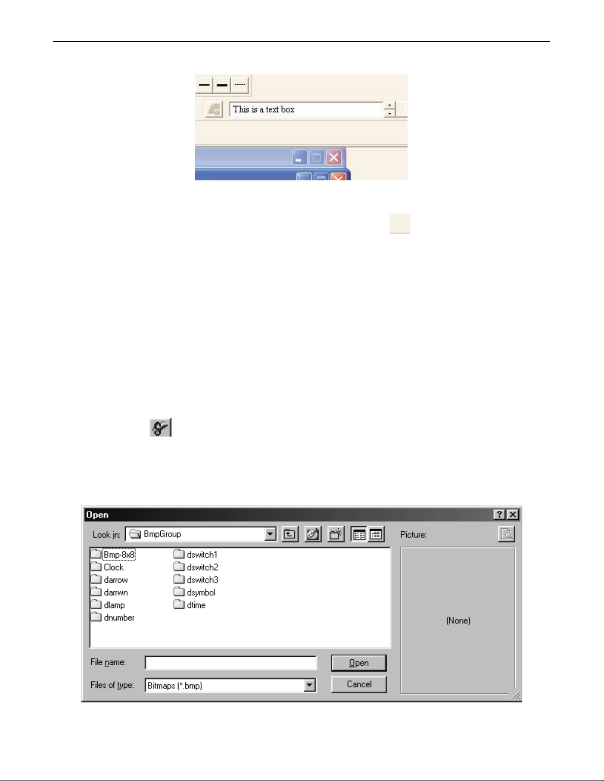
Creating Graphic Objects 81
4To quickly edit the text box
1. You can edit the text of a text box by clicking on the text object and then making changes in the Text
Input box located on the Text/Graphic Toolbar.
2. You can also change the font by clicking on the font button in the Text/Graphic Toolbar.
Predefined Bitmaps
In addition to using the drawing tools to create your own graphics, BlueLeaf software provides several libraries of predefined
bitmaps of various sizes and shapes. These bitmaps are stored in libraries that come with BlueLeaf software, (more on
libraries in the next section). Bitmaps are to display a predefined complex graphics object on the OIT screen. Bitmaps are
pixel-based graphics which are stored in files that contain information about each pixel to compose a bitmap graphic. The
pixel is the smallest possible detail that you can change on a screen. Bitmaps are used in both passive and active graphics
objects. Each bitmap can be placed anywhere on the screen but cannot be resized. The following examples show how to
place a pre-defined bitmap on the OIT screen as a passive object. Using bitmaps with active graphics objects is covered in
Chapter 6 - Representing Data with Graphics Objects. Information on how to create new bitmaps and store them into
libraries will be covered in a later section of this chapter.
Using a Predefined Bitmap
You can select from many bitmaps that are included in the BlueLeaf software configuration software. Bitmaps can be used
for active or passive objects. The following procedure describes using a passive bitmap object.
4To use a bitmap
1. From the
mouse cursor over the screen area, it changes to a crosshair cursor.
2. Click anywhere on the screen edit area to place a bitmap. A 16-by-16 pixel box with small white
boxes around the perimeter appears.
3. Double-click on the bitmap to display the Open Bitmap dialog box:
DRAW menu, click Bitmap. Or click the Bitmap icon in the Draw toolbar. As you move the
1010-0300, Rev 02
Page 84

82 Blue Series Installation & Operation Manual
4. Double-click on any of the libraries to open that folder and display the bitmaps within that library:
5. Click on any of the bitmap files and use the Preview Box to view the bitmap. To select the bitmap,
click Open.
6. The bitmap will now appear on the main screen of BlueLeaf software, highlighted with small white
boxes around the perimeter.
7. Move the bitmap to the location desired by clicking and dragging the object.
8. The bitmap cannot be resized. To change the size of the bitmap, you must vary the size using some
other graphics design software.
Creating Custom Bitmaps
Custom bitmaps can be created using Microsoft® Paint or an other graphics-design software. To create a bitmap using
Microsoft Paint, perform the following steps.
1. Open Paint.
2. On the VIEW menu, point to Zoom, and then click Custom.
3. Under Zoom to, click 800%, and then click OK.
4. On the View menu, point to Zoom, and then click Show Grid.
5. Create your bitmap with any of the tools.
6. Save the bitmap to the BmpGroup folder in the BlueLeaf directory.
* The BLU300M display is only 128 x 64 pixels and only displays black or white.
1010-0300, Rev 02
Page 85

Using Dynamic Objects 83
Chapter 7 - Using Dynamic Objects
BlueLeaf software includes several active graphics objects or ‘parts’ that are used to represent data that is stored in the PLC
or controller. The data represented can be single bit coils, 16-bit, or 32-bit registers. The data can be represented as
numbers, ASCII characters, or as graphic shapes or bitmaps. This chapter focuses on only parts that perform relatively
simple functions. More complex parts used for alarms, trending, etc. will be reserved for later chapters.
Representing PLC Coil Registers
PLC coils (or binary registers) and internal coils of the OIT are represented using three parts: the Bit Lamp Object, the Word
Lamp Object, and the Multi-state Bitmap Object. Each has a particular function that makes them unique but they are all
constructed and used in essentially the same manner.
The Bit Lamp Object
The Bit Lamp Object is a simple way to represent the value of a PLC coil using predefined bitmaps that represent the On and
Off state of the PLC coil. The object continuously reads the PLC coil and displays the corresponding bitmap that is tagged to
the On or Off state of the coil.
4To create a Bit Lamp Object
1. From the
mouse cursor changes to a crosshair. Select the location on the screen to place the Bit Lamp and left
click the mouse to place a Bit Lamp object on the screen. Move the mouse cursor over the Bit Lamp
object and double-click the Bit Lamp object. The Edit Bit Lamp Object dialog box appears.
2. In the PLC/Controller Address frame, enter the PLC coil or controller address. Or click the
OBJECTS menu, click Bit Lamp. Or click the Bit Lamp icon in the Objects toolbar. The
1010-0300, Rev 02
Page 86

84 Blue Series Installation & Operation Manual
PLC/Controller Address button to display the Edit PLC/Controller Address dialog
box:
\
3. In the Reference Address area, click the pull-down box to select the target PLC memory area. Use the
numeric keypad to enter the specific PLC memory address. Select the PLC Network Address (if
applicable) and HMI communications port. Click Enter to go back to prior dialog box.
4. In the Bitmap Setting frame, select which Bit Lamp object to display for the ON state and the OFF
state. There are eighteen predefined bitmaps from which to select from (to use a custom bitmap or text
labels, you must use the Multi-State Bitmap w/Label object).
5. Click OK. The Bit Lamp Object is displayed on the main screen of BlueLeaf with the appropriate
bitmap displayed. If necessary, use the mouse to drag the part to the location on the window that you
want it. Note: the Bit Lamp object is always preset to 16x16 pixels in size and cannot be changed.
The Word Lamp Object
The Word Lamp Object is used to represent the value of a PLC data register. The object continuously reads the PLC register
and displays the corresponding bitmap that is tagged to each state of the register. A maximum of five states can be created, as
shown in the example below:
4To create a Word Lamp Object
1. From the
The mouse cursor changes to a crosshair. Select the location on the screen to place the Word Lamp
OBJECTS menu, click Word Lamp. Or click the Word Lamp icon in the Objects toolbar.
1010-0300, Rev 02
Page 87

Using Dynamic Objects 85
and left click the mouse to place a Word Lamp object on the screen. Move the mouse cursor over the
Word Lamp object and double-click the Word Lamp object. The Edit Word Lamp Object dialog box
appears.
2. In the PLC/Controller Address frame, enter the PLC coil or controller address. Or click the
PLC/Controller Address button to display the Edit PLC/Controller Address dialog
box:
3. In the Reference Address area, click the pull-down box to select the target PLC memory area. Use the
numeric keypad to enter the specific PLC memory address. Select the PLC Network Address (if
applicable) and HMI communications port. Click Enter to go back to prior dialog box.
1010-0300, Rev 02
Page 88
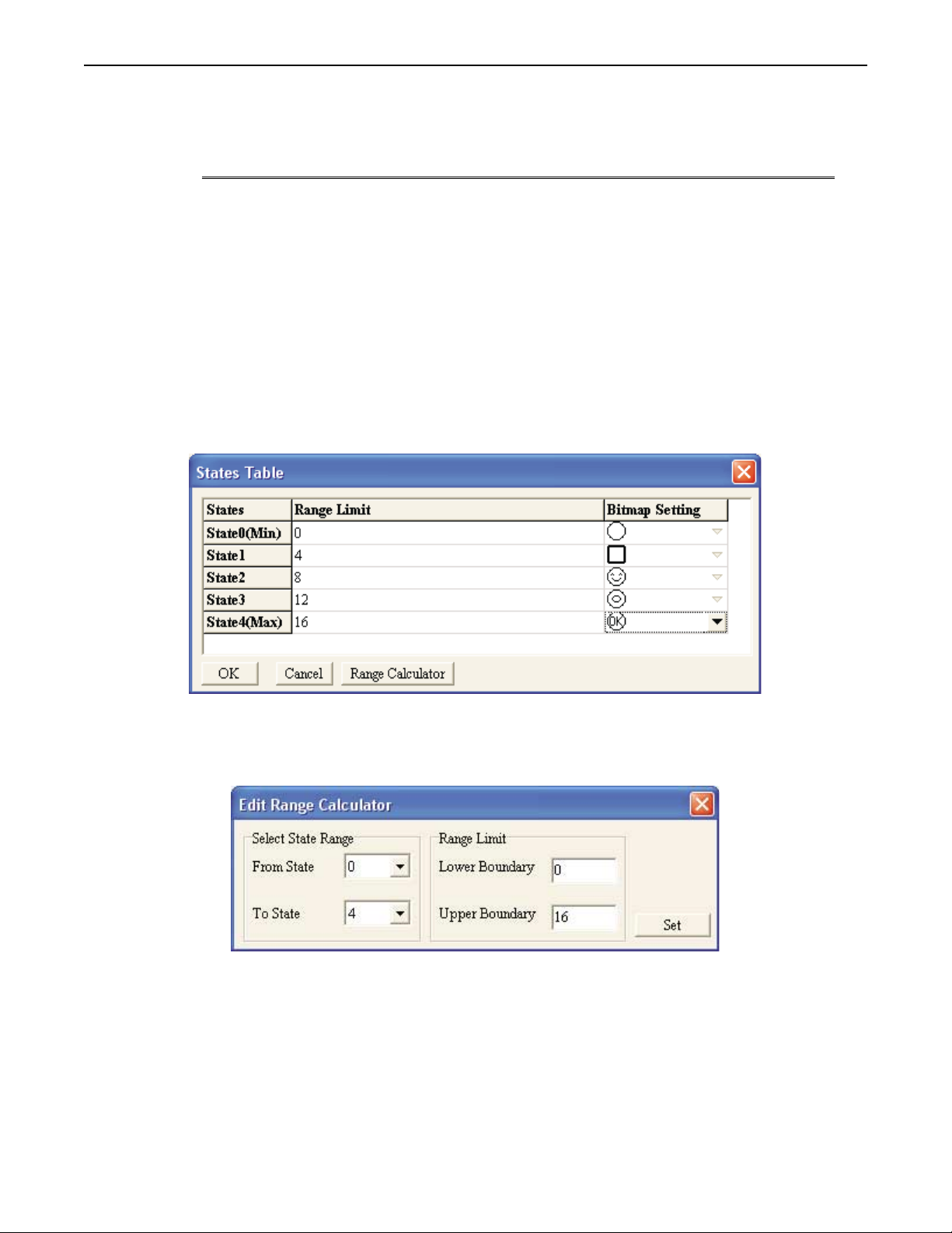
86 Blue Series Installation & Operation Manual
4. In the Format: box, use the pull-down box to select the format that determines how the OIT interprets
the value in the PLC register. Select from:
Format Range
Unsigned 0 to 65535 16 unsigned 16 bit format
0 to 4294967295 32 unsigned 32 bit format
Signed -32768 to +32767 16 signed 16 bit format
-2147483648 to +2147483647 32 signed 32 bit format
Hexadecimal 0000 to FFFF 16 hexadecimal 16 bit format
00000000 to FFFFFFFF 32 hexadecimal 32 bit format
BCD 0000 to 9999 16 BCD 16 bit format
00000000 to 99999999 32 BCD 32 bit format
Size
(Bits)
Description
5. In the Size: box, use the pull-down box to select 16 bit or 32 bit register.
6. Click the Show State Table button to display the Edit Word Lamp State Table dialog box:
7. For each State, enter the Range Limit that determines if that state’s bitmap is to be displayed. The
range limit number entered must be larger than the prior state and smaller than each successive state, as
shown in the example above. You can also click the Range Calculator button to display the Range
Calculator:
8. The Range Calculator is a tool to help you easily determine the ranges. By setting the minimum value
to be represented (lower boundary) and maximum value to be represented (upper boundary), the
calculator will evenly divide the range for each state. Click the Set button to go back to the prior dialog
box.
9. In the Bitmap Setting: box select a bitmap for each state. There are eighteen predefined bitmaps from
which to select from (to use a custom bitmap or text labels, you must use the Multi-State Bitmap
w/Label object). Click OK to accept the settings and go back to the Edit Word Lamp Object dialog
box.
10. Click OK. The Word Lamp Object is displayed on the main screen of BlueLeaf with the appropriate
bitmap displayed. If necessary, use the mouse to drag the part to the location on the window that you
want it. Note: the Word Lamp object is always preset to 16x16 pixels in size and cannot be changed.
1010-0300, Rev 02
Page 89

Using Dynamic Objects 87
The Multi-State Bitmap w/Label Object
The Multi-State Bitmap w/Label Object is very similar to the Bit Lamp and the Word Lamp objects. It is also used to read
values from a PLC coil or register but there are three additional features:
option to use text labels instead of bitmaps
•
assign bitmaps selected from any of the predefined bitmap libraries or use your own
•
create more than five state word lamps- up to 255 states
•
4To create a Multi-State Bitmap w/Label Object
1. From the
in the Objects toolbar. The mouse cursor changes to a crosshair. Select the location on the screen to
place the Multi-State Bitmap and left click the mouse to place a Multi-State Bitmap object on the
screen. Move the mouse cursor over the Multi-State Bitmap object and double-click the Multi-State
Bitmap object. The Edit Multi-State Bitmap w/Label dialog box appears.
OBJECTS menu, click Multi-State Bitmap w/Label. Or click the Multi-State Bitmap icon
2. First select either Bit or Value to determine if the Multi-State Bitmap object will read from a PLC coil
or a PLC register (16 or 32 bit).
3. For Value Only- If reading from a PLC/controller register, use the Format: pull-down box to select
the format that determines how the OIT reads the value in the PLC register. Select from:
Format Range
Unsigned 0 to 65535 16 unsigned 16 bit format
0 to 4294967295 32 unsigned 32 bit format
Signed
Hexadecimal 0000 to FFFF 16 hexadecimal 16 bit format
BCD 0000 to 9999 16 BCD 16 bit format
-32768 to +32767 16 signed 16 bit format
-2147483648 to +2147483647 32 signed 32 bit format
00000000 to FFFFFFFF 32 hexadecimal 32 bit format
00000000 to 99999999 32 BCD 32 bit format
Size
(Bits)
Description
4. For Value Only- In the Size: box, use the pull-down box to select 16 bit or 32 bit register.
5. For Value Only- Use the Total States: box to enter the total number of states to be represented. Use
the up/down scroll keys to change the value. Range is 1 to 255.
1010-0300, Rev 02
Page 90

88 Blue Series Installation & Operation Manual
6. In the PLC/Controller Address frame, enter the PLC coil or register address. Or click the
PLC/Controller Address button to display the Edit PLC/Controller Address dialog box:
Check the Memory Area box. Click the pull-down box to select the target PLC memory area. Use
the numeric keypad to enter the specific PLC memory address. Select the PLC Network Address (if
applicable) and HMI communications port. Click Enter to go back to prior dialog box.
7. Click the Font button to select the font that will be used for any text labels created for each state in the
Show State Table.
8 Click the Show State Table button to display the States Table dialog box:
1010-0300, Rev 02
9. For each State, enter the Range Limit which determines if that state’s bitmap or text label is to be
displayed. The range limit number entered must be larger than the prior state and smaller than each
successive state, as shown in the example above. You can also click the Range Calculator button to
display the Range Calculator:
The Range Calculator is a tool to help you easily determine the ranges. By setting the minimum value
to be represented (lower boundary) and maximum value to be represented (upper boundary), the
calculator will evenly divide the range for each state. Click the Set button to go back to the prior dialog
box.
Page 91

Using Dynamic Objects 89
10. In the Label: box, you can enter text that is displayed when the state is valid. The length of the text
string is limited to the size and type of font you have selected and the width of the OIT screen. For
example, for font MS Serif 6, a maximum of 32 characters can be used.
11. In the BMP Read box select a bitmap for each state. This is done by clicking on the directory
button to display the BmpGroup library directory:
12. Click on any of the listed subdirectories. Select the bitmap you wish to use, then click Open. Click
OK to accept the settings and go back to the Edit Multi-State Bitmap State Table dialog box.
13. Click OK. The Multi-State Bitmap Object is displayed on the main screen of BlueLeaf with the
appropriate bitmap displayed. If necessary, use the mouse to drag the part to the location on the
window that you want it. Note: the Multi-State Bitmap object can be resized once placed on the screen
to fit the largest bitmap in the series. Simply click the up/down arrows of the State: box while the
Multi-State Object is highlighted to scroll through each state. When the largest bitmap is displayed,
click on the small white boxes located around the perimeter of the selected object to resize the object.
The Clock Display Object
The Clock Display Object is used to display the time and/or date using the OIT’s built-in clock or by reading a PLC register.
4To create a Clock Display Object
1. From the
The mouse cursor changes to a crosshair. Select the location on the screen to place the Clock Display
and left click the mouse to place a Clock Display object on the screen. Move the mouse cursor over
OBJECTS menu, click Clock Display. Or click the Clock Display icon in the Objects toolbar.
1010-0300, Rev 02
Page 92

90 Blue Series Installation & Operation Manual
the Clock Display object and double-click the Clock Display object. The Edit Clock Display Object
dialog box appears.
2. In the Time Source frame, select HMI or PLC as the source of the clock information. If HMI is
selected, the frame to the right will change to Write to… This field is used to select a PLC address that
will be used to write the current time and date. If PLC is selected, the frame to the right will change to
Read from… This field is used to select a PLC address that the HMI uses to read the current time and
date. Whether reading from or writing to a PLC register, the HMI requires seven consecutive 16-bit
registers for the clock data. Using the PLC address in the example above, the registers would be as
follows:
Range
PLC Register Clock Data
(binary
Example
format)
4x1 Year 00-99 2004 = 04
4x2 Day of Week 1-7 Monday =1, Sunday =7
4x3 Month 1-12 January =1, December =12
4x4 Date (Day of Month) 1-31
4x5 Hour (24hr format) 0-23 1= 1am, 12= noon, 18=6pm
4x6 Minute 0-59
4x7 Second 0-59
1010-0300, Rev 02
Page 93

Using Dynamic Objects 91
3. Click the PLC/Controller Address button to display the Edit PLC/Controller Address dialog
box:
4. In the reference address area, click the pull-down box to select the target PLC memory area. Use the
numeric keypad to enter the specific PLC memory address. Select the PLC Network Address (if
applicable) and HMI communications port. Click Enter to go back to prior dialog box.
5. Select Time, Week,orDate to determine the type of clock data to be displayed.
6. In the Frame: box, use the pull-down box to select the type of frame that surrounds the clock data.
7. In the Font: box, use the pull-down box to select the font size of the clock display.
8. In the Alignment: box, select Right, Left,orMiddle alignment.
9. Use the Style box to select the format you want to use when displaying the time or the date.
Type Style Description
Time HHMMSS 24hr format (hr, min, sec)
HHMM 24hr format (hr,min)
HHMMSSa 12hr format (hr, min, sec, a/p)
HHMMa 12hr format (hr, min, a/p)
Week MON - SUN day of week
Date YYYY/MM/DD year, mon, day
MM/DD/YYYY mon, day, year
DD/MM/YYYY day, mon, year
MM/DD/YY mon, day, yr
DD/MM/YY day, mon, yr
10. Click OK. The Clock Display Object is displayed on the main screen of BlueLeaf with the appropriate
format displayed. If necessary, use the mouse to drag the part to the location on the window that you
want it. You can also resize the clock display object by moving the mouse cursor over any of the small
white boxes around the perimeter of the object. The mouse cursor will change to a double-arrow.
Then click on the box and drag the box to change size.
1010-0300, Rev 02
Page 94

92 Blue Series Installation & Operation Manual
The Dynamic Messages Object
The Dynamic Messages Object is used to display predefined text messages depending upon the value read from a PLC
register or coil. This feature can be used to display alarm messages or other information to the plant floor operator.
4To create a Dynamic Messages Object
1. From the
Objects toolbar. The mouse cursor changes to a crosshair. Select the location on the screen to place
the Dynamic Message and left click the mouse to place a Dynamic Message object on the screen.
Move the mouse cursor over the Dynamic Message object and double-click the Dynamic Message
object. The Edit Dynamic Message Object dialog box appears.
OBJECTS menu, click Dynamic Messages. Or click the Dynamic Messages icon in the
2. Check Bit to select a PLC coil. Check Value to select a PLC register.
3. In the PLC/Controller Address frame, enter the PLC coil or register address. Or click the
PLC/Controller Address button to display the Edit PLC/Controller Address dialog box:
4. In the Reference Address area, click the pull-down box to select the target PLC memory area. Use the
numeric keypad to enter the specific PLC memory address. Select the PLC Network Address (if
applicable) and HMI communications port. Click Enter to go back to prior dialog box.
5. If Value is selected, enter the Total States by using the scroll buttons. The Total States parameter
determines the number of messages that can be created and displayed. Up to 255 states can be
displayed.
6. For Value Only- In the Format box, select the type of PLC register to be read from: Unsigned,
Signed, Hexadecimal, and BCD.
7. For Value Only- The Size box determines if a 16 or 32 bit register is to be read.
8. Select the type of special effects used to display the dynamic message in the Special Effect: frame:
1010-0300, Rev 02
Page 95

Using Dynamic Objects 93
Special Effect Description
Normal the message is displayed with no special effects.
Blink
Scroll
the entire message blinks on and off (regardless of
state every 2 sec)
the entire message will scroll across the area set
aside for the dynamic message according to four
settings: Bottom to top, Top to bottom, Right to left,
and Left to right. The Change Interval setting
determines the scroll rate.
9. Click the Font button to display the Font dialog box:
10. Select the font, style and font size. Click OK to go back to the prior dialog box.
11. Click the Show State Table button to display the Dynamic Messages States Table dialog box:
12. For each State, enter the Range Limit that determines if that state’s text message is to be displayed.
The range limit number entered must be larger than the prior state and smaller than each successive
1010-0300, Rev 02
Page 96

94 Blue Series Installation & Operation Manual
state, as shown in the example above. You can also click the Range Calculator button to display the
Range Calculator:
13. The Range Calculator is a tool to help you easily determine the ranges. By setting the minimum value
to be represented (lower boundary) and maximum value to be represented (upper boundary), the
calculator will evenly divide the range for each state. Click the Set button to go back to the prior
dialog box.
14. In the Message: box, you can enter the text that is displayed when the state is valid. The length of the
text string is limited to the size and type of font you have selected and the width of the OIT screen.
For example, for font MS Serif 6, a maximum of 32 characters can be used.
15. Click OK to go back to the Edit Dynamic Message Object dialog box.
16. Click OK. The Dynamic Message Object is displayed on the main screen of BlueLeaf with the
appropriate format displayed. If necessary, use the mouse to drag the part to the location on the
window that you want it. You can also resize the dynamic message by moving the mouse cursor over
any of the small white boxes around the perimeter of the object. The mouse cursor will change to a
double-arrow. Then click on the box and drag the box to change size.
1010-0300, Rev 02
Page 97

Entering & Displaying Numeric/ASCII Characters 95
Chapter 8 - Entering/Displaying Numeric and ASCII Characters
The BlueLeaf software includes two objects that are used to represent numeric or ASCII character data that is stored in the
PLC. The data represented can be single bit coils, 16-bit or 32-bit registers. The data can be displayed as numbers or ASCII
characters. This chapter focuses on the Numeric/ASCII Display object and the Numeric Input object.
Representing PLC Data Registers
PLC registers are represented using two objects:
Numeric/ASCII Display object
•
Numeric Input object
•
They are constructed in much the same manner as objects described in the previous section. With these objects, however, you
can represent data from 16-bit or 32-bit PLC registers.
The Numeric/ASCII Display Object
The Numeric/ASCII Display Object is used to display the numeric value of a PLC register, or to represent each 16-bit
register in the PLC, as two printable ASCII characters. The object continuously reads the PLC register and displays the
corresponding numeric data in the format specified. The PLC register can be a 16-bit or 32-bit word.
4To create a Numeric/ASCII Display object
1. From the
the Objects toolbar. The mouse cursor changes to a crosshair. Select the location on the screen to
place the Numeric/ASCII Display and left click the mouse to place a Numeric/ASCII Display object
on the screen. Move the mouse cursor over the Numeric/ASCII Display object and double-click the
Numeric/ASCII Display object. The Edit Numeric/ASCII Display Object dialog box appears.
OBJECTS menu, click Numeric/ASCII Display, or click the Numeric/ASCII Display icon in
1010-0300, Rev 02
Page 98
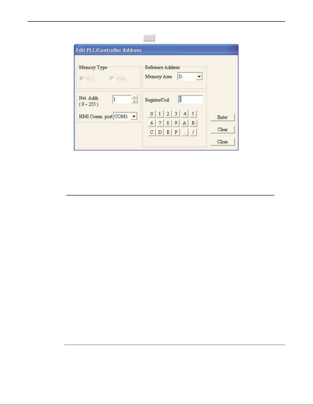
96 Blue Series Installation & Operation Manual
2. In the PLC/Controller Address frame, enter the PLC coil or controller address. Or click the
PLC/Controller Address button to display the Edit PLC/Controller Address dialog box:
3. In the reference address area, click the pull-down box to select the target PLC memory area. Use the
numeric keypad to enter the specific PLC memory address. Select the PLC Network Address (if
applicable) and HMI communications port. Click Enter to go back to prior dialog box.
4. In the Format attribute box, select the format type you wish to use. The options are:
Format Range
Unsigned 0 to 65535 16 unsigned 16 bit format
0 to 4294967295 32 unsigned 32 bit format
Signed
Hexadecimal 0000 to FFFF 16 hexadecimal 16 bit format
BCD 0000 to 9999 16 BCD 16 bit format
ASCII Printable characters 16 2 ASCII characters
Binary 00… to 11… (16 bits) 16 only binary 16 bit format
Floating -21474836 to +2147483648 32 only floating 32 bit only
-32768 to +32767 16 signed 16 bit format
-2147483648 to +2147483647 32 signed 32 bit format
00000000 to FFFFFFFF 32 hexadecimal 32 bit format
00000000 to 99999999 32 BCD 32 bit format
Printable characters 32 4 ASCII characters
Size
(Bits)
Description
5. In the Size attribute box, select either 16 bits or 32 bits.
6. In the Alignment attribute box, select how you wish to align the data that is displayed: left
justification, right justification, or centered.
7. The Int. Number and Dec. Number attribute boxes are used to specify the number of digits you want
displayed before/after a decimal point. For example, if you are monitoring a 16-bit PLC register
(+220) using signed format and have Int.Number =2 and Dec.Number =1, then the BLU300 displays
this number as +22.0.
1010-0300, Rev 02
* If the value in the PLC register requires more digits than you have allocated with the Int.
Number and Dec. Number, the HMI will only display the specified digits. For example, if the
value in the PLC register is +17,220 and Int.Number = 2 and Dec. Number = 1, then the HMI
will display +22.0 giving no indication that the actual value in the PLC register is larger.
Page 99

Entering & Displaying Numeric/ASCII Characters 97
Therefore, it is the responsibility of the HMI programmer to ensure the HMI settings are correct
for the PLC range to be used.
8. The Frame Outline attribute box allows you to enclose the data in a box. Select from- None, Single,
Double, Thick, Dot, or Dotted Line.
9. The Font Size can be 5x8 (width/height), 8x8, 8x12, or 8x16 pixels for each character.
10. Check Leading Zeroes to display the number with ‘padded’ zeroes to the left of the number in cases
where the number displayed is smaller than the number of digits allocated.
11. Click OK. The Numeric/ASCII Display Object is displayed on the main screen of BlueLeaf as a
numeric value of 0. Multiple 0’s will be displayed if the Leading Zeroes option is checked. If the
Type selected is Signed, than a $ symbol is displayed to indicate the ‘+/-‘ sign. If necessary, use the
mouse to drag the object to the location on the window that you want it. You can also highlight the
object to display the small white perimeter boxes and adjust the size. Move the mouse cursor over the
appropriate white box until the mouse cursor changes to a double-arrow symbol, then click and drag to
change the size.
The Numeric Input Object
The Numeric Input Object is used to read and write numeric values to a PLC register. The object continuously reads the PLC
register and displays the corresponding value in the specified format . The PLC register can be a 16-bit or 32-bit word. By
assigning a function key that displays an entry screen, the OIT operator can enter a new value using the arrow keys and/or the
function keys as a numeric entry keypad. The minimum/maximum values can be set and a password can be assigned to
restrict access. You can also use the Call Setting feature to set or clear a PLC coil before or after a new value is written to the
PLC register.
4To create a Numeric Input Object
1. From the
toolbar. The mouse cursor changes to a crosshair. Select the location on the screen to place the
Numeric Input and left click the mouse to place a Numeric Input object on the screen. Move the
mouse cursor over the Numeric Input object and double-click the Numeric Input object. The Edit
Numeric Input Address dialog box appears.
OBJECTS menu, click Numeric Input, or click the Numeric Input icon in the Objects
2. In the PLC/Controller Address frame, enter the PLC or controller address you wish to access in the
1010-0300, Rev 02
Page 100

98 Blue Series Installation & Operation Manual
Write attribute box, or click the PLC/Controller Address button to display the Edit
PLC/Controller Address dialog box:
3. In the Reference Address area, click the pull-down box to select the target PLC memory area. Use the
numeric keypad to enter the specific PLC memory address. Select the PLC Network Address (if
applicable) and HMI communications port. Click Enter to go back to prior dialog box.
4. If you wish to read the contents of a different
PLC register address, then check the Read
checkbox and enter the PLC address you wish to display. Or click on the PLC/Controller Address
button to display the Edit PLC/Controller Address dialog box. The BLU300 will then read
and display the contents of this register, but will still allow you to use a function key to display an
entry screen that allows you to write to the address listed in the Write attribute box.
* If you wish to read the same PLC register as that to which you are writing, then leave the Read
checkbox unchecked. It is not necessary to select the same address for the Read attribute, the
BLU300 will automatically assume that you wish to read the PLC register that is entered into the
Write attribute box.
5. To initiate the process of writing a new value, you must assign a function key to the Numeric Input
object. Check the Fun. Key attribute box, then select a function key from the drop-down list box.
* If you attempt to select a function key that has already been assigned to another Numeric Input
object on the same screen or a function key that has been assigned using the Local Function Key
Editor, an error message will be displayed notifying you that the key is currently being used.
6. In the Format attribute box, select the format type you wish to use. The options are:
Format Range
Unsigned 0 to 65535 16 unsigned 16 bit format
0 to 4294967295 32 unsigned 32 bit format
Signed
Hexadecimal 0000 to FFFF 16 hexadecimal 16 bit format
BCD 0000 to 9999 16 BCD 16 bit format
Floating -2147483648 to +2147483647 32 only Floating 32 bit format
-32768 to +32767 16 signed 16 bit format
-2147483648 to +2147483647 32 signed 32 bit format
00000000 to FFFFFFFF 32 hexadecimal 32 bit format
00000000 to 99999999 32 BCD 32 bit format
Size
(Bits)
Description
1010-0300, Rev 02
 Loading...