

Page 1

maplePrint
GUIDE
1
BUILD GUIDE
mapleMaker
ADDITIVE ENGINEERING
Page 2

SECTION
A
1.1 Introduction 2
1.2 Table of Contents 3
1.3 Required Tools 4
1.4 Reseller Information 5
1.5 Components 6
Page 3

Page 4
A
1.1
Introduction
Welcome, and Thank you!
Thank you for your interest in the mapleMaker Mini V2 3D Printer.
The mapleMaker Mini introduces you to the world of additive
manufacturing and 3D printing. With your own 3D printer, your
concepts and design ideas can be translated from computer
drawings to physical objects in short period of time.
The goal of this guide is to introduce you to the parts and pieces
that will be required before you can assemble your printer kit. Most
of these items can be sourced both locally and from any number of
online retailers.
The aim of this kit was to reduce costs and create an accessible,
hackable, upgradeable, and ultimately, user customizable
3D Printer. We believe that a 3D printer should evolve with it’s
users needs and knowledge, and become a platform for any
number of future upgrades and additions without the need for costly
re-works or additional components.
Ultimately though, we want to empower the next generation of
designers, developers, and engineers by giving them the platform
and tools to suite their needs for today, tomorrow, and well into
the future.
We are Open Source. Collaboration fuels Innovation.
Create, Innovate, and Share.
4
Page 5

Table of Contents
This guide is broken into several sections which encompasses the build process of the
maplePrint Mini 3D printer. The process begins with the basic frame assembly and nishes
with the nal wiring and installation.
While we try to maintain the most up to date diagrams and illustrations, there may be
slight dierences between the illustrations contained within this guide, and the printed
parts in your kit. If there are major changes or dierences between the instructions
contained within and the printed parts, you should have received an updated insert in
your kit containing the revised instructions.
A
1.2
Section A:
1.1 Introduction 2
1.2 Table of Contents 3
1.3 Required Tools 4
1.4 Reseller Information 5
1.5 Components 6
Section B:
2.1 Z Motor Assembly 16
2.2 Lower Frame Assembly 18
2.3 Upper Frame Assembly 24
2.4 Lower/Upper Frame Union 26
Section C:
3.1 Extruder Assembly 34
Section D:
4.1 X-Carriage Assembly 48
4.2 Y Carriage Assembly 62
4.3 Print Bed Assembly 76
4.4 Z Carriage Assembly 82
Section E:
5.1 GT2 Belt Installation 98
5.2 LCD Installation 102
5.3 RAMPS Installation 106
5.4 Upper Bed Installation 116
5 .5 Wiring & Final Configuration 118
Section F:
6.1 Appendix 136
5
Page 6

A
A
1.1
Required Tools
1.3
Before we begin the assembly process, it is vital that we have the proper tools to complete the build.
Thankfully though, there are only a few tools required for the build. These tools were either included
with your kit, or available at any local hardware or tool store.
You will need the following:
#2.5 Allen Key (for use with M3 screws)
#3 Allen Key (for use with M4 screws)
#4 Allen Key (for use with M5 screws)
Ceramic screw driver (for adjusting RAMPS drivers)
Spatula (to remove printed parts from the print bed)
Exacto Knife (for trimming and cleaning parts)
Needle nose or similar pliars
Solder iron and solder
Nylon wire ties or zip ties (for securing wiring looms)
3M Blue painters tape (for printing with PLA)
Hot glue gun (to secure endstops)
Additional information regarding this build guide:
We’ve attempted to keep this build guide simple and easy to understand. We’ve broken the
assembly into several sections, and each step into individual illustrations to simplify the build
process further. Each illustrated step in this guide is also accompanied by a list of parts and
hardware required to complete the step. The illustrations of fasteners in these lists are printed to
scale and may be used to size the hardware included in your kit. Simply place a fastener on top
of or next to the illustration to determine if its the correct one for the job!
6
Page 7

A
Reseller Information
Below is a list of resellers and manufacturers of the components used in the mapleMaker
Mini 3D Printer.
Some components may be sourced from your local home improvement retailers or
specialist hobby stores.
Electronics, motors & extruders
Folger Technologies, LLC: www.folgertech.com
Active Surplus: www.active123.com
EckerTech Inc: www.eckertech.com
Misumi www.us.misumi-ec.com/
Mixshop www.mixshop.com
Filastruder www.lastruder.com
A
1.4
1.1
SDP/SI CA www.sdp-si.com/
Skyhunt www.skyhunt.net
ROBOTDIGG www.robotdigg.com
Voxel Factory www.voxelfactory.com
Linear rods & movement
Folger Technologies, LLC: www.folgertech.com
ROBOTDIGG www.robotdigg.com
EckerTech Inc: www.eckertech.com
Mixshop www.mixshop.com
Fasteners
HD Supply Canada: www.brafasco.com (minimums may apply)
Fastenal www.fastenal.com (minimums may apply)
Misc. electronics
Digikey: www.digikey.ca
McMaster-Carr www.mcmaster.com (minimums may apply)
7
Page 8

A
Components
1.5
The following list comprises the components required to build your printer. For the purposes of this build,
we have used ROBOTDIGG (www.robotdigg.com) to source the majority of the components. ROBOTDIGG
oers almost every component required, minus fasteners and threaded rod. The hot end has been sourced
through e3D’s authorized distributor, Filastruder (www.lastruder.com)
NEMA 17 48oz Stepper Motor
Quantity: 3
URL: http://www.robotdigg.com/product/206/Nema17-48mm-Stepper-Motor
Unit Cost: $9.50
NEMA 17 34oz Stepper Motor
Quantity: 2
URL: http://www.robotdigg.com/product/28/NEMA14-34mm-0.8A-or-1.25A-stepper-motor
Unit Cost: $6.80
Flexible Coupling - 5mm to 5mm
Quantity: 2
URL: http://www.robotdigg.com/product/83/Flexible-Coupling-5mm-Shaft-to-5mm-Screw
Unit Cost: $1.80
20 Tooth GT2 Pulley
Quantity: 2
URL: http://www.robotdigg.com/product/166/2GT-20-Tooth-6.35mm-Bore-Pulley
Unit Cost: $1.85
Open Ended 6mm GT2 Belt (2 meters
Quantity: 1
URL: http://www.robotdigg.com/product/10/Open-Ended-6mm-Width-GT2-Belt
Unit Cost: $1.80
LMS8UU (Short) 8mm Linear Bearing
Quantity: 12
URL: http://www.robotdigg.com/product/13/LM8UU-Linear-Bearing
Unit Cost: $0.60
8
Page 9

623ZZ Ball Bearing
Quantity: 4
URL: http://www.robotdigg.com/product/62/623ZZ-Ball-Bearing
Unit Cost: $3.60
Poloululu 4988 Stepper Drivers
Quantity: 4
URL: http://www.robotdigg.com/product/120/A4988-stepper-driver
Unit Cost: $3.80
Endstop
Quantity: 3
URL: http://www.robotdigg.com/product/141/Endstop,-Snap-Action-Limit-Switch-SS-5GL
Unit Cost: $0.60
RAMPS 1.4 Controller
Quantity: 1
URL: http://www.robotdigg.com/product/121/Ramps-1.4-Board
Unit Cost: $12.80
Arduino Mega 2560
Quantity: 1
URL: http://www.robotdigg.com/product/123/Arduino-Mega-2560-R3
Unit Cost: $15.80
RAMPS LCD Display
Quantity: 1
URL: http://www.robotdigg.com/product/122/RAMPS-LCD2004-with-SD-Socket
Unit Cost: $12.80
30mm Cooling Fan
Quantity: 4
URL: http://www.robotdigg.com/product/197/12V-3CMHotend-Cooling-Fan
Unit Cost: $1.50
9
Page 10

A
Components
1.5
12V 5A Power Supply
Quantity: 1
URL: http://www.robotdigg.com/product/350/12V-5AAC/DC-Adapter-Power-Supply
Unit Cost: $5.00
NEMA 17 34oz Stepper Motor
Quantity: 2
URL: http://www.robotdigg.com/product/28/NEMA14-34mm-0.8A-or-1.25A-stepper-motor
Unit Cost: $6.80
Thermistor Cable (1m)
Quantity: 1
URL: http://www.robotdigg.com/product/188/2pin-1MLong-Thermistor-Cables-w/-Dupont-Connector
Unit Cost: $0.40
Endstop Cables (1m)
Quantity: 3
URL: http://www.robotdigg.com/product/189/3pin-1MLong-Endstop-Cables-w/-Dupont-Connector
Unit Cost: $0.60
e3D Lite6 All Metal Hot End
Quantity: 1
URL: http://www.lastruder.com/products/lite6
Unit Cost: $35.00
MK8 Extruder Drive Gear
Quantity: 1
URL: http://www.robotdigg.com/product/242/MK8-Filament-Drive-Gear
Unit Cost: $3.00
Compression Spring (for Extruder & bed)
Quantity: 5
URL: http://www.robotdigg.com/product/71/Compression-Spring-for-Heatbed-and-Extruder
Unit Cost: $2.00
10
Page 11

762mm length Linear Rods (Pack of 6)
Quantity: 1
URL: http://www.robotdigg.com/product/113/Rostock-Mini-492mm-Long-8mm-Diameter-Smooth-Rod-Pack
Unit Cost: $24.00
Allen Key Set
Quantity: 1
URL: http://www.robotdigg.com/product/128/1.5,-2,-2.5,-3,-4-size-allen-key-with-ball-head-in-pack
Unit Cost: $2.00
Nylon Cable Ties (100 pack)
Quantity: 1
URL: http://www.www.robotdigg.com/product/127/Nylon-Cable-Ties-2.5*100mm-100pcs-n-3.6*200mm-
100pcs-Pack
Unit Cost: $1.80
Ceramic Screwdriver
Quantity: 1
URL: http://www.robotdigg.com/product/181/Ceramicscrewdriver-for-A4988-stepper-driver
Unit Cost: $1.20
4GB SD Card
Quantity: 1
URL: http://www.robotdigg.com/product/345/4GB-SDCard-for-3D-Printing
Unit Cost: $4.50
Fasteners & Threaded Rod:
You will also require the following fasteners and threaded rod to complete the build.
These items can be purchased from your local hardware retailer or online.
M3X10mm Socket Cap Screw x135
M3X20mm Socket Cap Screw x8
M3X16mm Socket Cap Screw x8
M4X10mm Socket Cap Screw x1
M4X16mm Socket Cap Screw x2
M5X12mm Socket Cap Screw x60
M4X40mm Socket Cap Screw x1
4mm - 0.7 Stainless Steel Threaded rod
4mm - 0.7 Flat nut x3
11
Page 12
A
1.5
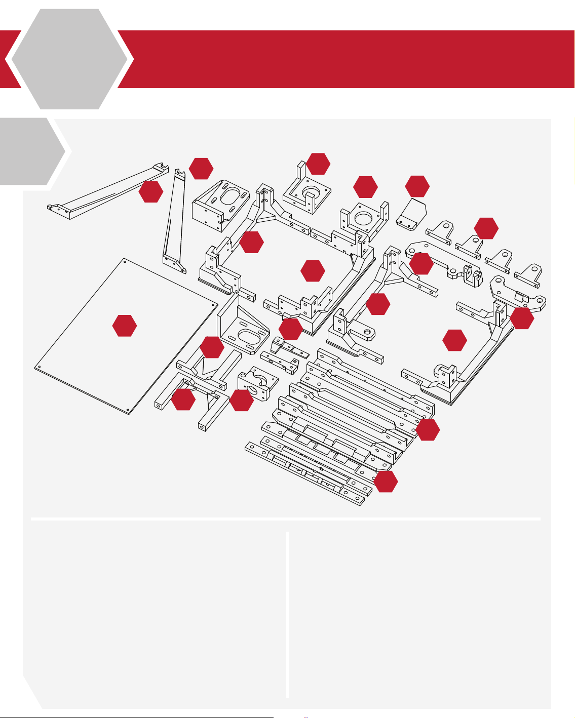
Printed Components
1
14
13
10
12
11
17
5
6
1
2
3
18
19
7
8
9
4
16
12
1. Left Lower Frame
2. Right Lower Frame
3. Right Upper Frame
4. Left Upper Frame
5. Left Z Motor Mount
6. Right Z Motor Mount
7. Z Axis Linear rod Mounts
8. Y Axis Carrier (Front)
9. Y Axis Carrier (Rear)
10. Y Axis Mount (Front)
15
11. Y Axis Mount (Rear)
12. Y Axis Motor Mount
13. Spool Holder Mounts (2)
14. Upper Bed (Printed)
15. Lower/Upper Frame rails (4)
16. Frame Upright Rails (4)
17. Extruder Mount
18. Extruder Idler Arm
19. Print Cooler Duct
Page 13
20
A
1.5
2
21
22
23
33
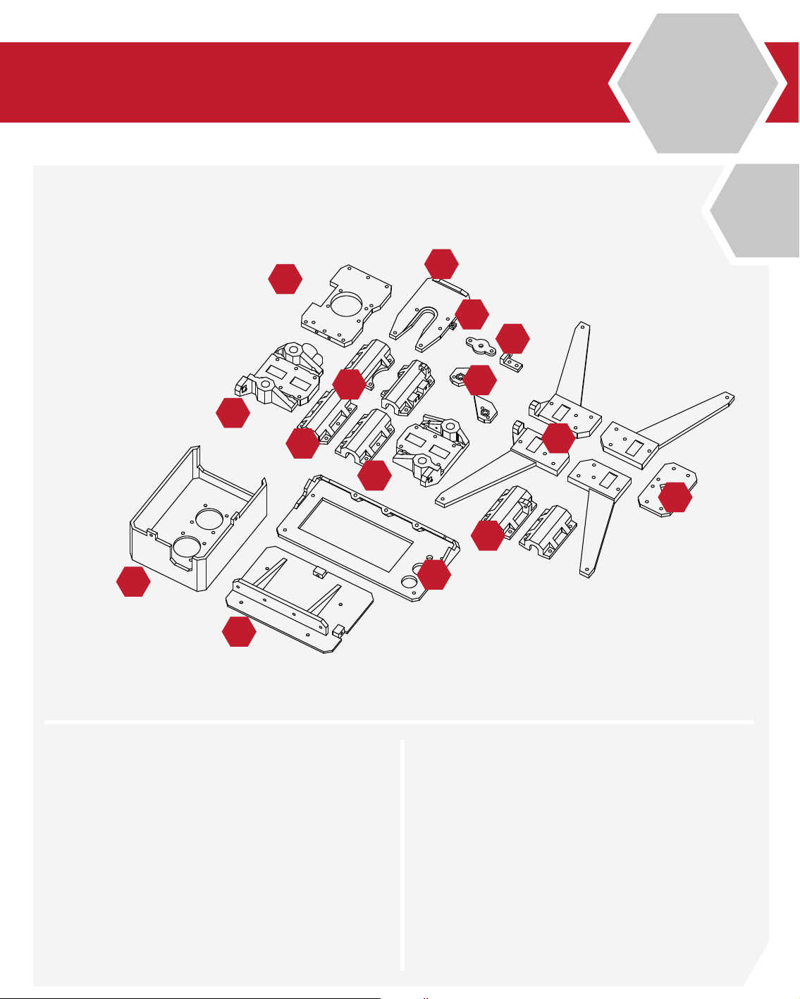
20. Extruder Base Mount
21. Hot-End Mount
25
32
28
27
24
30
26
31
29
34
28. Z Axis Bearing Carriers (2)
29. Y Axis Bearing Carriers (2)
22. X Axis Idler Cover
23. Z Axis Adjustment Mount
24. Z Axis Nut Covers
25. X Axis Assembly (Left)
26. X Axis Assembly (Right)
27. X (Extruder) Bearing Carriers (2)
30. Lower Bed Frame (4)
31. Lower Bed Union
32. Electronics Backplate
33. Electronics Enclosure
34. LCD Frame Assembly
13
Page 14

SECTION
2.1 Z Motor Assembly 16
2.2 Lower Frame Assembly 18
2.3 Upper Frame Assembly 24
B
2.4 Lower/Upper Frame Union 26
Page 15
Page 16
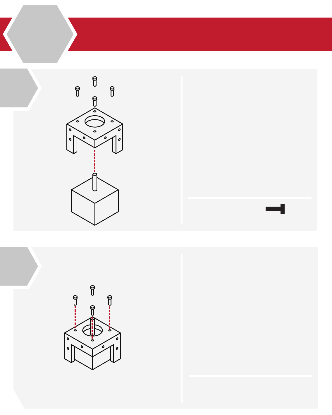
1
B
2.1
Z Motor Assembly (Right Front)
Locate the Hardware bag marked:
Z-Motor Mounts
Locate the Right Front Motor mount, the
upright mounts should face the outside of
the frame.
From the Stepper Motor package, select 1 of
the 34mm (short) stepper motors.
From the Fastener package, select:
4 M3x10 cap screws
2
X 4
Insert the Stepper Motor into the base of the
Right Front Motor Mount
The threads on the face of the Stepper Motor
should align with the 4 holes of the Right
Front Motor Mount.
M3 x 10
16
N/A
Page 17
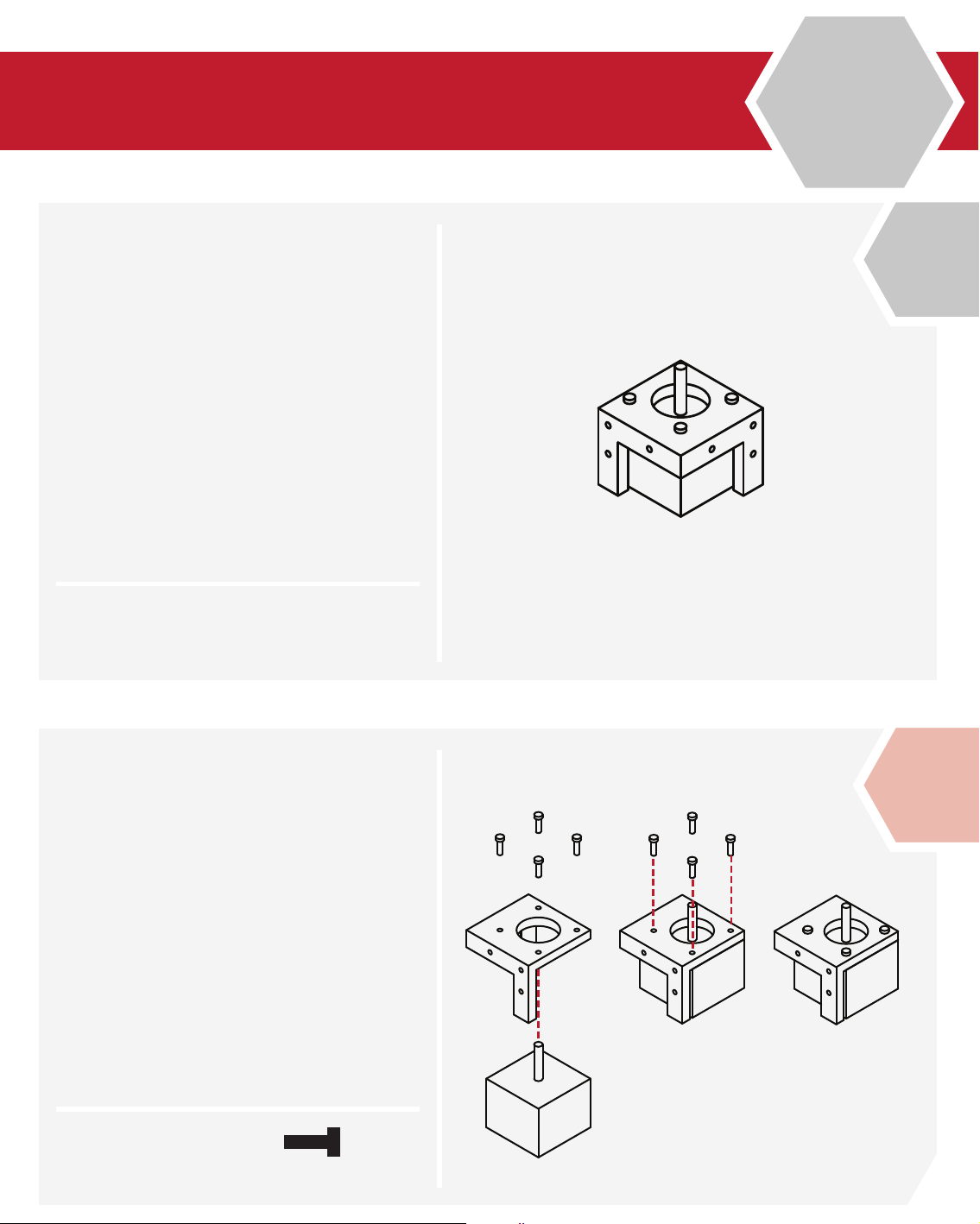
Z Motor Assembly (Right/Left Front)
Using the M3 Hex wrench, screw the
4 M3 x 10 cap screws through the Right
Front Motor mount into the stepper motor.
Note: Take care not to over-tighten the
screws, or you may break the motor mount.
Congratulations, the Right Front Z Motor
Assembly is complete!
B
2.1
3
N/A
Alert: Left Front Z Motor Assembly
Collect the Left Front Motor Mount, the
second 34mm (short) stepper motor and
4 M3x10 cap screws.
Repeat Steps 1-3 to complete the Left Front
Z Motor Assembly
!
X 4
M3 x 10
17
Page 18
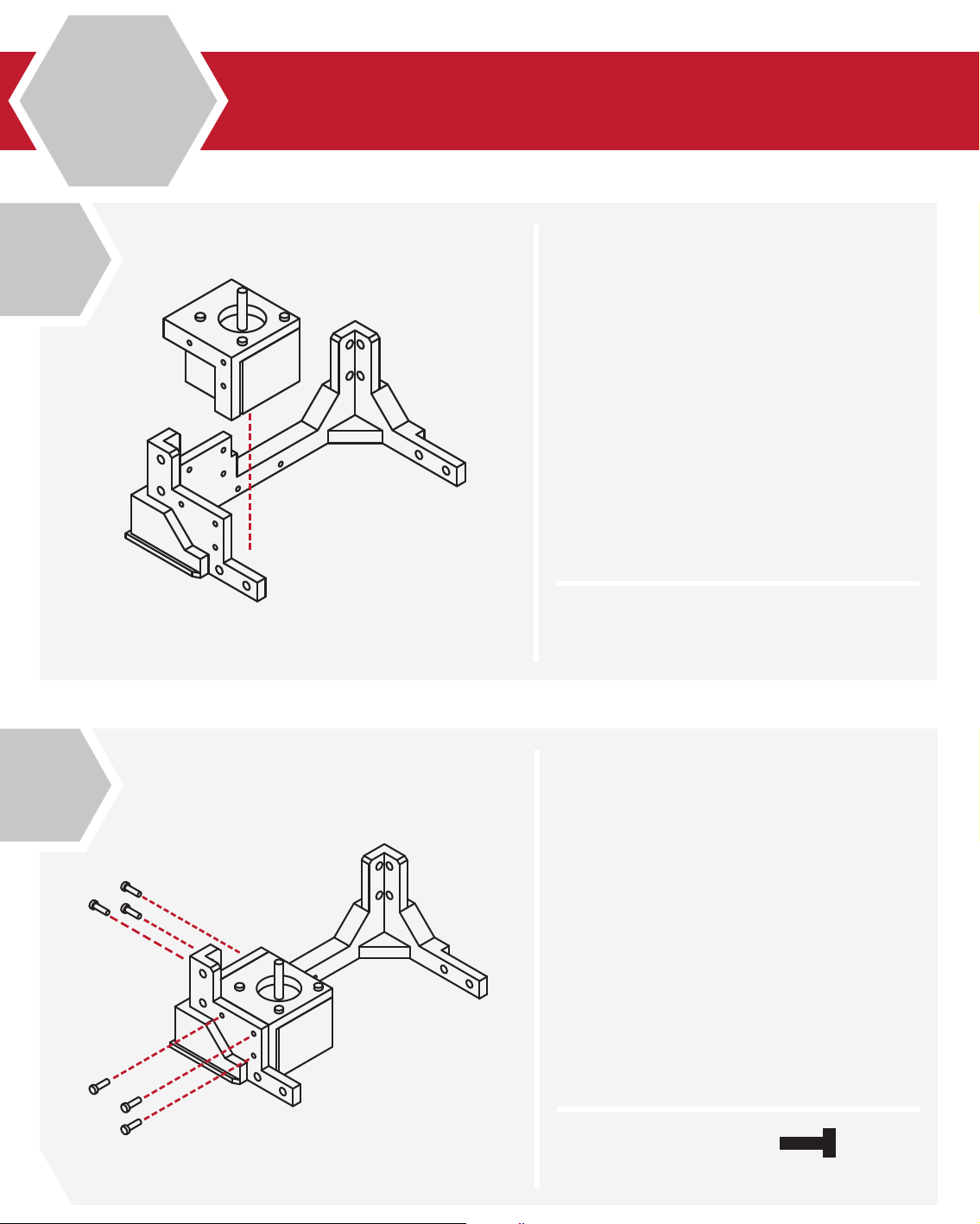
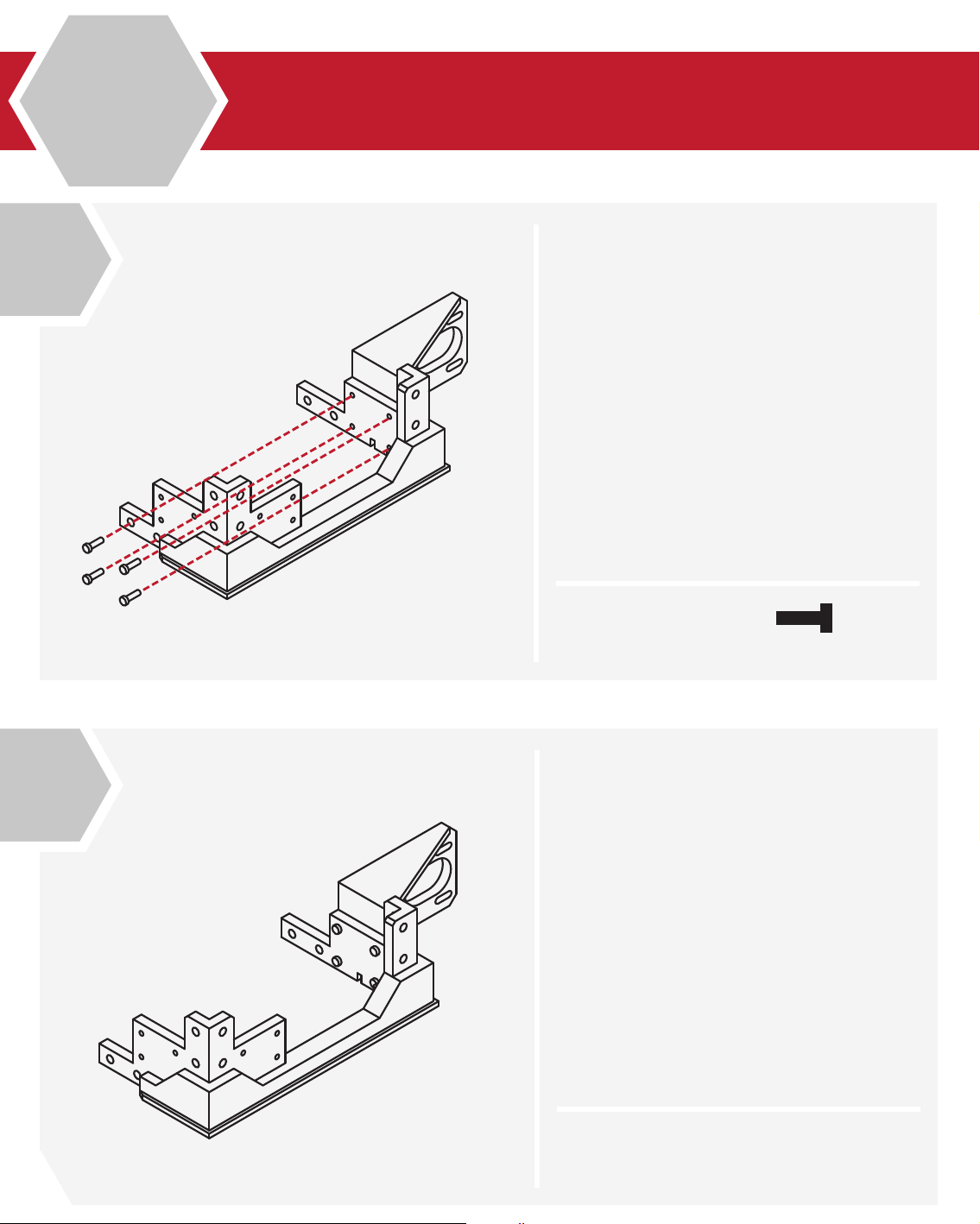
1
B
2.2
Lower Frame Assembly
Locate the lower left side frame, and collect the left Z motor assembly completed
in the previous steps.
Place the motor assembly into the lower
left frame.
The screw holes on the motor assembly
should match the screw holes in the lower
left frame assembly.
2
N/A
From the hardware bag, collect 6 M3 X 10
screws.
Using your M3 Hex wrench, attach the
motor assembly to the lower frame assembly.
18
X 6
M3 x 10
Page 19
Congratulations, you’ve completed the
left lower frame assembly.
Check the t and ensure that all screws are
tight.
Don’t over tighten the screws, as this may
strip the parts.
B
2.2
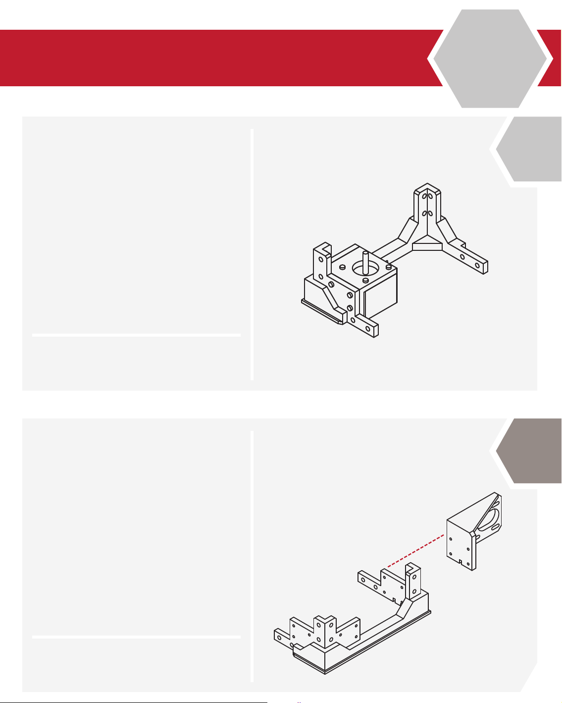
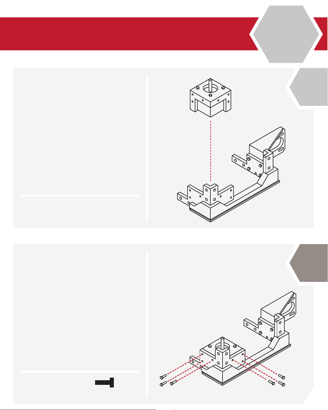
3
N/A
Locate the Y axis motor mount from your
printed parts kit. This mount is longer than
the similar X axis motor mount.
Also from your printed parts, locate the
lower right side frame.
Check the tment of both pieces before
proceeding to the next step.
4
N/A
19
Page 20
5
B
2.2
Lower Frame Assembly
From the hardware bag, select 4 M3 X 10
screws.
Using the screws, attach the Y axis motor
mount to the lower right side frame.
6
X 4
The Y axis motor mount is now complete.
Check the tment of the mount to the
lower frame.
Ensure that the mount is tight to the
frame and secure.
Do not over-tighten the screws holding
the mount in place.
M3 x 10
20
N/A
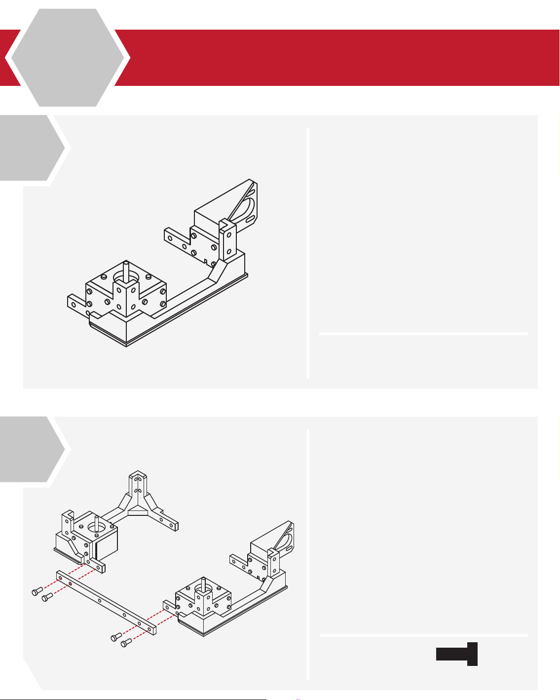
Page 21
Locate the right Z motor assembly that
was assembled in the previous steps.
Place the motor assembly into the lower
right frame.
The screw holes on the motor assembly
should match the screw holes in the lower
right frame assembly.
B
2.2
7
N/A
From the hardware bag, collect 6 M3 X 10
screws.
Using your M3 Hex wrench, attach the
motor assembly to the lower frame assembly.
8
X 6
M3 x 10
21
Page 22
1
B
2.2
Lower Frame Assembly
Congratulations, you’ve completed the right
lower frame assembly.
Check the t and ensure that all screws are
tight.
Don’t over tighten the screws, as this may
strip the parts.
2
N/A
From the printed parts kit, locate the front
lower frame rail. The front lower frame rail
should be longer in length than the rear.
Take the left and right lower frame
assemblies and match it to the lower front
frame rail.
From the hardware bag select 4 M5 X 12
screws and using your hex wrench screw
them through the lower front rail and into the
left and right lower frame assemblies.
Check to make sure the pieces align and there
are no gaps.
22
X 4
M5 x 12
Page 23
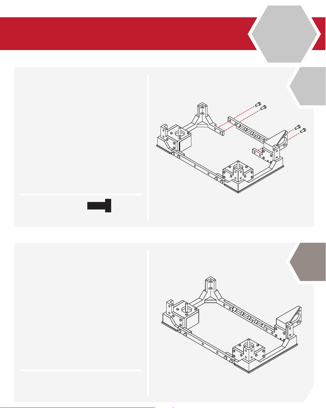
Similar to the previous step, select the
rear lower frame rail from the parts kit. This
rail is longer than the front lower rail.
Select 4 M5 X 12 screws from the hardware
bag.
Like the previous step, take the screws and
using your hex wrench attach the rear frame
rail to the lower frame assemblies.
Ensure that the screws are tight and that
there are no gaps or alignment issues with
the pieces.
B
2.2
3
X 4
Congratulations! You’ve completed the
lower frame assembly!
Take a break and marvel at your
accomplishment.
M5 x 12
4
N/A
23
Page 24
1
B
2.3
Upper Frame Assembly
The upper frame assembly is similar to the lower frame
assembly. You will need to locate the left and right upper
frame assemblies, as well as the front and rear upper
frame rails.
The front frame rail is easily identied by the 3 screw
holes for the LCD panel. You will also need to collect
8 M5 X 12 screws from the hardware bag.
Like the lower assembly, use your hex wrench to secure
the upper frame rails to the upper frame assemblies.
24
X 8
M5 x 12
Page 25
B
2.3
2
N/A
Congratulations! You’ve assembled the upper frame
assembly! Wasn’t that easy?
Take a moment to check that the frame appears square
and that the frame rails are tight to the frame assemblies.
Ensure that the screws are not over-tightened as well.
25
Page 26
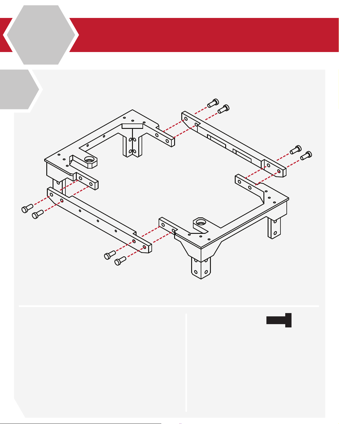
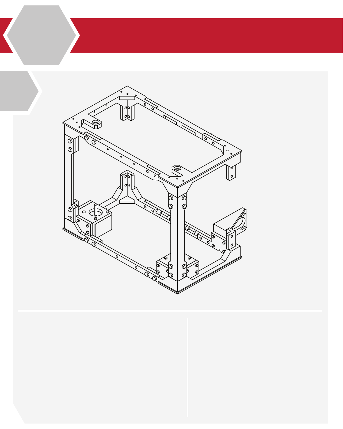
1
B
2.4
Lower & Upper Frame Union
From the parts kit, select 2 of the main frame uprights.
These pieces are universal and can be tted in any posi-
tion.
Select 8 M5 X 12 screws from your hardware bag as well.
Using your hex wrench, install the screws into the frame
uprights, and then into the lower and upper frame as-
sembly.
It is best to assemble the lower frame before the upper
frame assembly.
26
X 8
M5 x 12
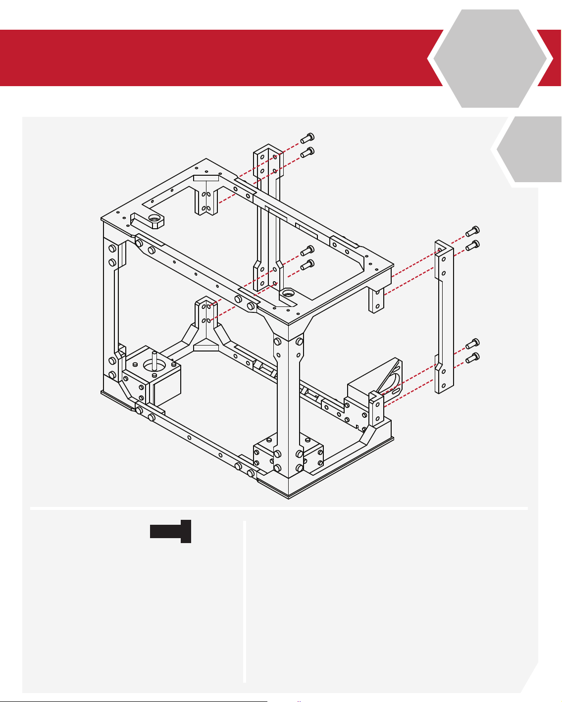
Page 27
B
2.4
2
X 8
M5 x 12
With the rst uprights installed, from your hardware
bag, select 8 additional M5 X 12 screws.
Using your hex wrench, install the screws into the
uprights.
Ensure that the uprights are tight and aligned to the
upper and lower frame assemblies.
27
Page 28
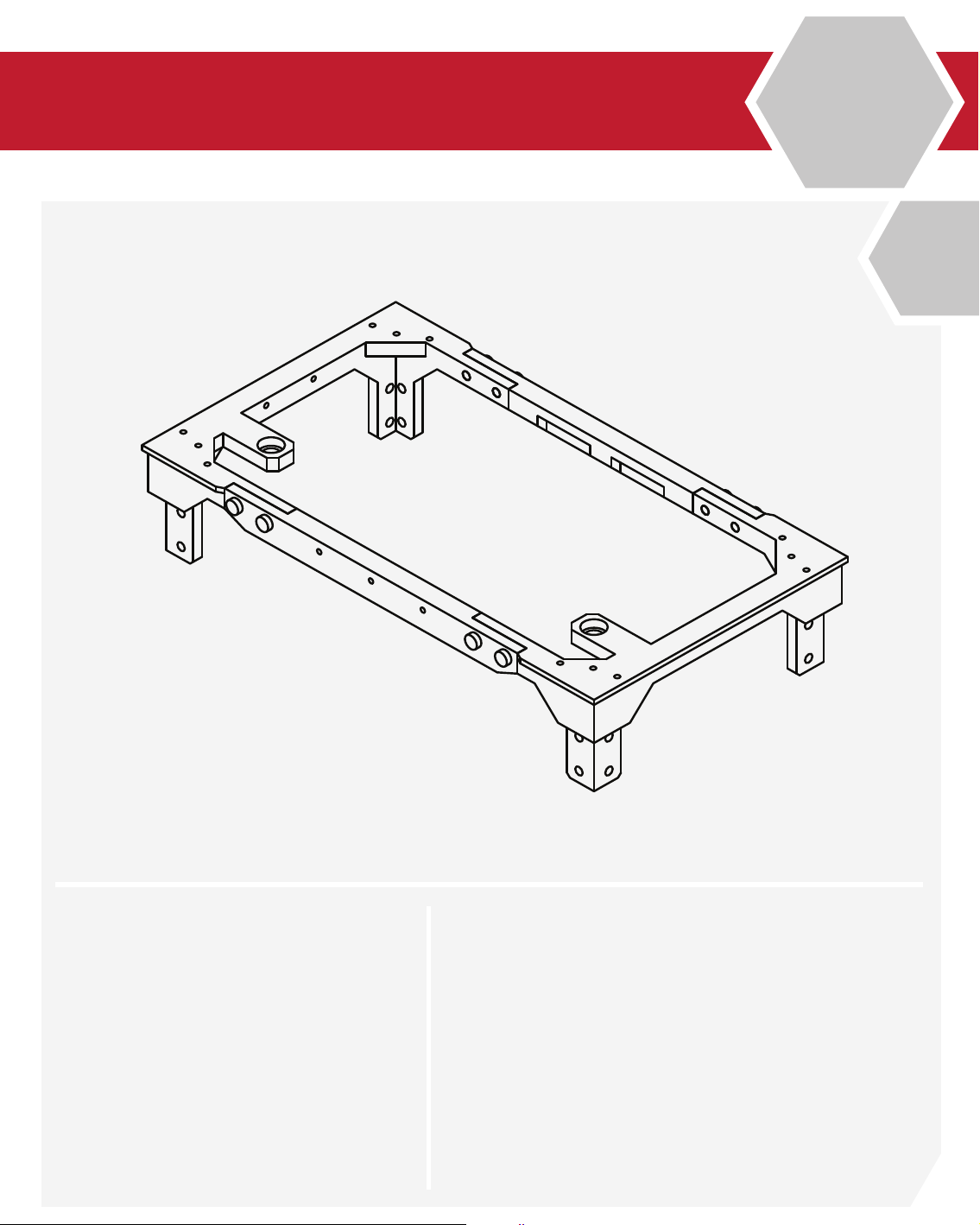
3
B
2.4
Lower & Upper Frame Union
Congratulations! You’ve installed half of the frame!
We’re almost done!
28
N/A
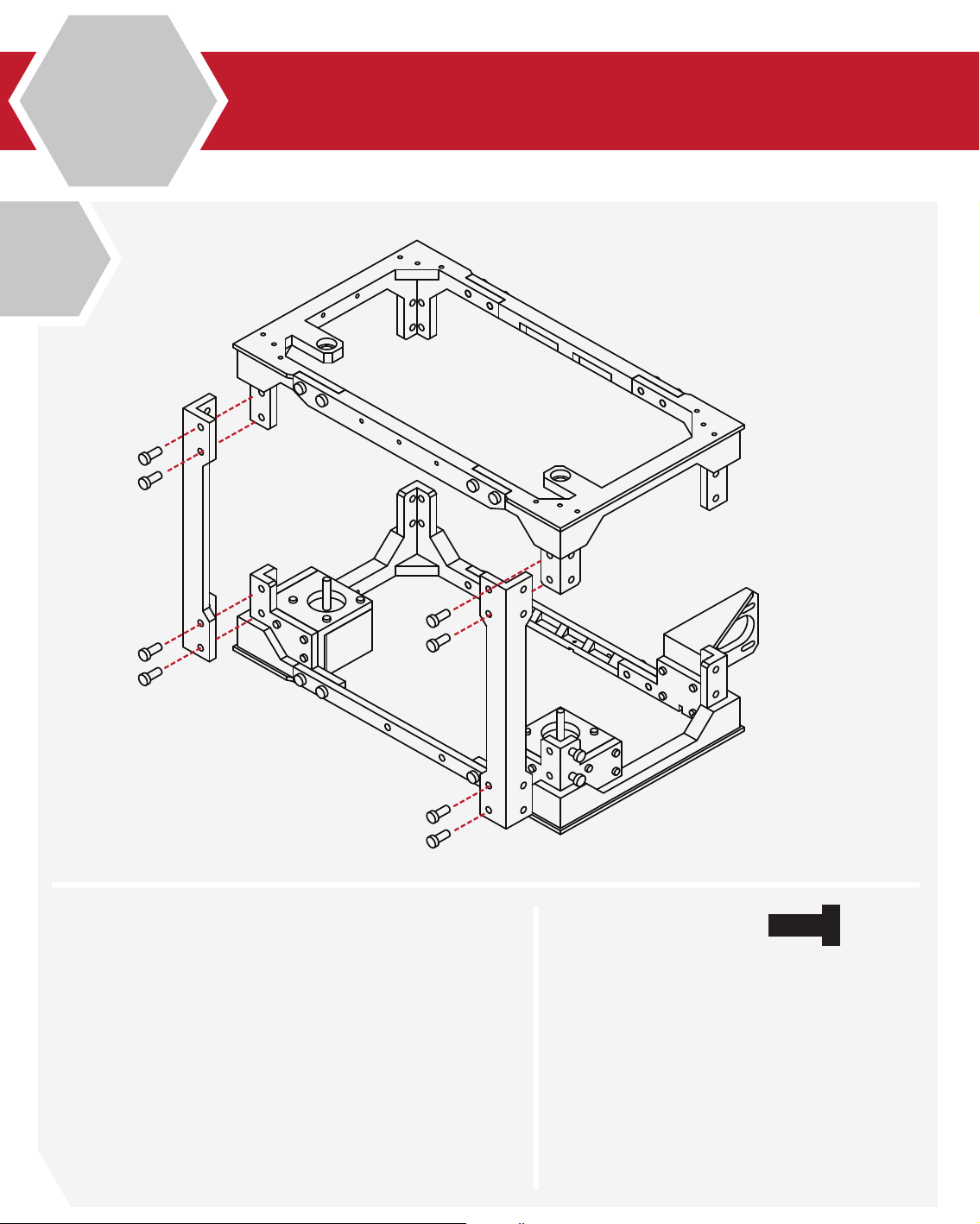
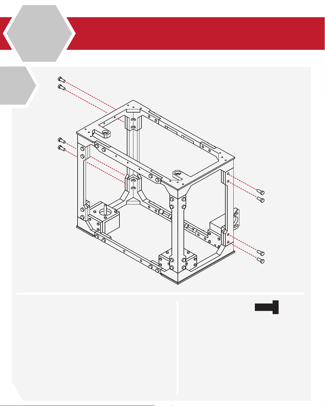
Page 29
B
2.4
4
X 8
M5 x 12
Like our previous step, select the two remaining frame
uprights and check their tment to the rest of the frame
assembly.
Select 8 M5 X 12 screws from the hardware bag.
Using your hex wrench, attach the two uprights to the
rear of the frame.
29
Page 30
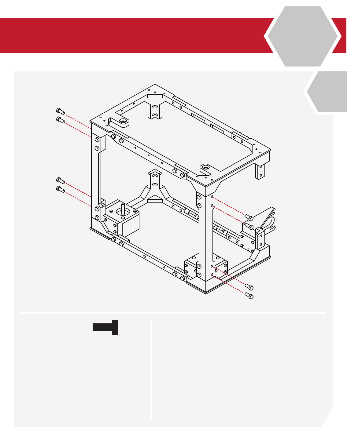
5
B
2.4
Lower & Upper Frame Union
Select 8 additional M5 X12 screws from your
hardware bag.
Using your hex wrench, install the remaining screws into
the uprights and frame assemblies.
30
X 8
M5 x 12
Page 31

B
2.4
6
N/A
Congratulations! You’ve completed the outside frame!
This frame makes up the structural elements of
your printer, and is the building block for the remaining
elements!
You’ve done an awesome job, and I’m sure it looks
amazing!
Take a moment to relax and marvel at your feat of
engineering, we’re going to be kicking it up a notch
in the next chapter!
31
Page 32

SECTION
C
3.1 Extruder Assembly 34
Page 33

Page 34

1
C
3.1
Extruder Assembly
From the hardware kit, locate 4 LMS8UU
linear bearings, and the 2 lower extruder
bearing carriers. These can be identied by
their semi circle cut outs.
Insert the bearings into the bearing carriers.
Take care not to damage the bearings as they
are inserted.
2
N/A
When fully inserted, the bearings shoul
protrude slightly fom the carriers.
Ensure that the bearings are aligned, and fully
seated before proceeding to the next step.
34
N/A
Page 35

C
3.1
3
X 10
M3 x 10
Locate the lower extruder base from the hardware kits.
From the hardware bag, select 10 M3 X 10 screws.
Align the lower bearing carriers with the extruder base.
The semi circle cut-outs should align with the opening in
the extruder base.
Using your hex wrench, install 5 of the screws into each
of the bearing carriers, and into the extruder base.
35
Page 36

4
C
3.1
Extruder Assembly
With the carriers mounted to the extruder
base, check that the parts t well and that
there are no lose screws.
The bearings should be solidly captured and
should not rattle or move once the pieces are
assembled.
5
N/A
Locate your hot-end from the parts kit. We
will be wiring and installing the remainder of
its components later in this build.
Locate the hot-end mounting plate from
your hardware kit as well.
Insert the hot-end into the mount.
The ange on the hot-end should seat snuggly up against the lower mount.
36
N/A
Page 37

Check that there is not any excessive play in
the mount.
If there is any play in the mount, use a small
piece of tape on the mount to shim the
hot-end.
If the play is excessive, contact us for
a replacement or solution.
C
3.1
6
N/A
Select 2 M3 X 10 screws from your hardware
set.
Install the screws into the hot-end mount,
and into the extruder base.
Ensure that the mount is securely attached to
the lower frame assembly.
7
X 2
M3 x 10
37
Page 38

8
C
3.1
Extruder Assembly
From the hardware kit, select one of the
remaining 48mm stepper motors, as well
as the MK8 extruder gear and the included
grub screw.
9
N/A
Place the extruder drive gear onto the shaft of
the stepper motor.
Use the small hex wrench to slightly tighten
the grub screw to hold the gear in place.
We will need to ne-tune the gear’s location
later in this guide, so do not tighten the screw
completely.
38
N/A
Page 39

C
3.1
9
X 3
M3 x 10
Locate the upper extruder mount from the hardware kit,
and 3 M3 X 10 screws.
Insert the stepper motor into the extruder mount.
Take note to orientate the position of the motor such that
the wire connectors are facing upwards.
Insert the 3 M3 X 10 screws through the extruder mount
and into the stepper motor.
39
Page 40

10
C
3.1
Extruder Assembly
Locate 2 M3 X 10 screws and 1 M3 X 20 screws.
Take the lower extruder assembly and the upper
extruder assembly from the previous steps and mate
them together. The screw holes should align.
Insert the M3 X 20 screw into the right-rear hole, and
the 2 remaining screws into the other openings.
Check that the screws are tight, and that the mount is
secure. The hot-end should also be rmly in place with
no slop or play.
40
X 2
X 1
M3 x 10
M3 x 20
Page 41

Locate both the front and rear extruder
arm components, as well as 2 M3 X 10,
and 1 M3 X 20 screws.
Place the two arm components face to face.
The screw holes should align.
Insert the M3 X 10 screws into the arms to
secure them together. Place the M3 X 20
screw into the last opening.
C
3.1
11
X 2
X 1
The extruder arm is almost complete. Check
that all the screws are tight and that the parts
t correctly.
M3 x 10
M3 x 20
12
N/A
41
Page 42

13
C
3.1
Extruder Assembly
Locate 1 radial ball bearing and 1 M4 X 10
screw from the hardware kit.
Insert the bearing into the opening of the
extruder arm, and using your hex wrench
install the screw into the arm, and through
the bearing.
When tight, the bearing should still rotate
freely.
14
X 1
Locate 1 M4 X 40 screw, 1 compression
spring, 2 washers, and one M4 nut.
Place the screw through the extruder
arm, afterwards place one washer, the
compression spring, a second washer,
and nally the nut onto the screw.
Thread the nut partially compress the spring.
M4 x 10
42
X 1
M4 x 40
Page 43

C
3.1
15
N/A
Using the extruder assembly from the previous step,
take the completed extruder arm and place it onto the
extruder assembly.
The longer screw on the extruder arm should slot into
the base of the extruder. The at faces of the nut
should also match the side of the extruder base as well.
43
Page 44

16
C
3.1
Extruder Assembly
Insert a washer between the extruder arm
and extruder assembly.
Screw the last M3 X 20 screw from the
extruder arm into the extruder assembly
and stepper motor.
The arm should move freely. By tightining or
loosening the extruder spring screw, you can
adjust the tension between the extruder gear
and idler bearing. For now, set the tension so
that the idler bearing is pressing against the
extruder gear.
17
N/A
Select one of the 30mm cooling fans from
your parts kit, and 2 M3 X 16 screws.
Using your hex wrench, attach the cooling
fan to the side of the extruder assembly.
The cooling fan should sit ush with the
extruder assembly.
44
X 2
M3 x 16
Page 45

C
3.1
18
X 2
X 2
M3 x 16
M3 x 10
Select one of the 30mm cooling fans, and the fan duct
from your parts kit.
Select 2 M3 X 16 and 2 M3 X 10 screws from your
hardware kit as well.
Attach the cooling fan to the fan duct using the M3 X 16
screws, and attach the fan duct to the extruder assembly
using the M3 X 10 screws.
45
Page 46

SECTION
4.1 X Carriage Assembly 48
4.2 Y Carriage Assembly 62
4.3 Print Bed Installation 76
D
4.4 Z Carriage Assembly 82
Page 47

Page 48

1
D
4.1
X Carriage Assembly
Locate the Z Axis bearing holders from your
parts kit, and 2 linear bearings from the
hardware kits.
The Z axis bearing holders are identied by
their 6 screw holes and slight chamfer on the
leading edge.
Press the linear bearings into the bearing
carrier and ensure that they are fully seated
and aligned.
2
N/A
Fromy your parts kit, locate the left X axis
mount. The left X axis mount is identiable by
its semi-circle idler mounts on the rear.
Press the bearings and bearing holders into
the X axis mount.
Ensure that the bearings and bearing carrier
are ush with the mount and insert the
6 M3 X 10 screws to secure the bearing and
holder in place.
48
X 6
M3 x 10
Page 49

The left X axis mount is now complete.
D
4.1
Check that the bearing holder is tight to the
X axis mount.
N/A
Locate one of the M4 nuts from the hardware
kit along with 2 M3 X 10 screws, along with
the Z axis capture plate.
3
4
Insert the nut into the X axis carriage.
Using your hex wrench, insert the screws into
the capture plate, and then attach the plate
to the X axis assembly.
Take care not to damage the X axis mount or
over tighten the screws.
X 2
M3 x 10
49
Page 50

5
D
4.1
X Carriage Assembly
Take the completed X axis assembly and
locate the idler bearing cover plate, along
with 1 idler bearing, 1 M4 X 16 and 2 M3 X
20 screws.
Insert the screws through the cover plate, and
place the idler bearing onto the M4 screw.
Using your hex wrench, screw the assembly
into the X axis assembly.
6
X 2
X 1
The left X assembly is now complete. Check
that the idler bearing spins freely, and that all
screws are tight and secure.
M3 x 20
M4 x 16
50
N/A
Page 51

Locate the Z Axis bearing holders from your
parts kit, and 2 linear bearings from the
hardware kits.
The Z axis bearing holders are identied by
their 6 screw holes and slight chamfer on the
leading edge.
Press the linear bearings into the bearing
carrier and ensure that they are fully seated
and aligned.
D
4.1
7
N/A
Fromy your parts kit, locate the right X axis
mount. Ensure that the bearings and bearing
carrier are ush with the mount and insert the
6 M3 X 10 screws to secure the bearing and
holder in place.
Locate one of the M4 nuts from the hardware
kit along with 2 M3 X 10 screws, along with
the Z axis capture plate.
Insert the nut into the X axis carriage.
Using your hex wrench, insert the screws into
the capture plate, and then attach the plate
to the X axis assembly.
8
X 6
M3 x 10
51
Page 52

9
D
4.1
X Carriage Assembly
Locate the X axis motor mount, and right X axis mount.
From your hardware kit, select 4 M3 X 10 screws.
Align the X axis mount with the motor mount, and using
your hex wrench install the 4 screws.
Ensure that the motor mount is ush and tight with the X
axis mount.
52
X 4
M3 x 10
Page 53

From the hardware kit, select one of the
remaining 48mm stepper motors, as well as
the GT2 Pulley.
D
4.1
10
N/A
Place the GT2 Pulley onto the shaft of the
stepper motor.
Use the small hex wrench to slightly tighten
the grub screw to hold the gear in place.
We will need to ne-tune the pulley’s location
later in this guide, so do not tighten the screw
completely.
11
N/A
53
Page 54

12
D
4.1
X Carriage Assembly
From your hardeare kit, locate 4 M3 X 10 screws, and
gather the stepper motor and X axis assembly from the
previous steps.
Insert the stepper motor into the motor mount. Ensure
that the cable connector on the motor is facing upwards.
Using your hex wrench, insert the 4 M3 X 10 screws into
the motor mount and into the stepper motor. We will be
adjusting the motor tension later in this guide, so there is
no need to completely tighten the screws.
54
X 4
M3 x 10
Page 55

D
4.1
13
N/A
Congratulations! You’ve completed the X motor
assembly.
Take a moment to ensure that all the scews and parts t
correctly and are tight.
55
Page 56

14
D
4.1
X Carriage Assembly
Locate the left X assembly from the previous steps as
well as 2 250mm linear rod.
These rods are the same length as the rods used for the
Z axis, but shorter than those used for the Y axis. Using a
soft mallet, gently drive the rods into the X assembly.
Take care to ensure the rods are inserted square to the
assembly and that you do not damage the X axis
assembly. When fully inserted, the rods should rest
against the small openings on the backside of the
X axis assembly.
56
N/A
Page 57

D
4.1
15
X 2
X 1
M3 x 10
M3 x 20
Locate the Z Axis screw mount from your parts kit, along
with 2 M3 X 10, and 1 M3 X 20 screws.
Using your hex wrench, attach the Z axis screw mount to
the outside of the X axis assembly.
Take the remaining M3 X 20 screw and screw it partially
through the mount. This will be used to level your initial
layer height later on.
57
Page 58

16
D
4.1
X Carriage Assembly
Locate the Extruder assembly that we assembled earlier
in this guide.
Orientate the extruder so that the hot-end cooling fan is
facing the X axis assembly.
Carefully slide the extruder assembly onto the linear rods.
Be careful when doing so, as it is easy to mis-align the
rods, and damage the bearings.
58
N/A
Page 59

D
4.1
17
N/A
With the extruder assembly in place, collect the right
X axis assembly that we assembled earlier.
Using a soft mallet, gently insert the X axis assembly onto
the linear rods.
Take care not to damage the X assembly or linear rods.
If you nd it particularily dicult, you can remove the 4
screws holding the motor assembly, and use the backside of X axis to hammer against directly. The linear rods
should be ush with the backside of the X axis assembly.
59
Page 60

18
D
4.1
X Carriage Assembly
From your hardware kit, select 2 M3 X 10 screws.
Using your hex wrench, insert the screws into the
backside of the extruder assembly.
The screws should sit roughly 6mm proud of the extruder
assembly. These will be used later in this guide to secure
the GT2 belts.
60
X 2
M3 x 10
Page 61

D
4.1
19
X 1
M3 x 20
Locate 1 M3 X 20 screw from your hardware kit.
Using your hex wrench, insert the screw partially
into the extruder assembly.
This screw will be used later to adjust your X axis
end-stop.
61
Page 62

1
D
4.2
Y Carriage Assembly
Locate the lower Y bearing carriers, and 4 linear
bearings from your parts kit.
Insert the bearings into the bearing carriers.
Ensure that the bearings are fully seated before
proceeding.
62
N/A
Page 63

D
4.2
2
N/A
Gather the 4 lower Y bed pieces from your parts kit and
arrange them like so.
63
Page 64

3
D
4.2
Y Carriage Assembly
Arrange the lower Y bed pieces such that the
indentations for the bearings align.
Ensure that the pieces t well.
You may use a sharp Exacto-knife or le to trim any parts
that do not t well.
64
N/A
Page 65

D
4.2
4
X 8
M3 x 10
From your hardware kit, locate 8 M3 X 10 screws. Gather
the bearing carriers that were assembled previously.
Using your hex wrench, install the 8 screws into the
bearing carriers, and then into the Y bed frame
components.
65
Page 66

5
D
4.2
Y Carriage Assembly
Ensure that all parts t correctly and that all screws
are tight.
The bearings should be rmly captured in their carriers
and should have little play in them.
66
N/A
Page 67

D
4.2
6
X 8
M3 x 10
Locate the Y bed cross member from your parts kit,
along with 8 M3 X 10 screws.
Using your hex wrench, install the screws into the cross
member, and then into the lower bed assembly.
67
Page 68

7
D
4.2
Y Carriage Assembly
With the cross member installed, ensure that all parts t
well and that all screws are tight.
68
N/A
Page 69

D
4.2
8
X 2
M3 x 10
Locate 2 M3 X 10 screws from your hardware kit.
Insert the screws into the 2 mounting points on the side
of the lower bed.
The screws should sit 6mm proud of the mount.
These screws will be used to secure the GT2 belt to later
in this guide.
69
Page 70

7
D
4.2
Y Carriage Assembly
Locate 1 M3 X 20 screw from your hardware kit and install it into the screw mount on the rear of the lower bed
assembly.
This screw will be used to home the bed later in your
conguration.
70
X 1
M3 x 20
Page 71

D
4.2
8
N/A
Congratulations! The lower bed assembly is complete!
Double check that all the fasteners are tight and that all
the parts are properly aligned.
71
Page 72

9
D
4.2
Y Carriage Assembly
From your parts kit, locate the front Y axis
carrier. Locate 1 bearing and 1 M4 X 16 screw
from your hardware kit.
Insert the bearing into the bearing holder,
and using youe hex wrench, insert the screw
into the bearing holder and bearing.
10
X 1
Ensure that the bearing can rotate freely in its
holder.
This bearing will act as the idler for the GT2
belt which will be installed later in this guide.
M4 x 16
72
N/A
Page 73

D
4.2
11
N/A
Locate the longest linear rods from your hardware kit.
Using a soft mallet, gently insert the linear rails into the
Y axis carrier.
Take care to ensure the rods are square and that the
carrier is not damaged.
When fully inserted, the face of the rods should be ush
with the face of the carrier.
73
Page 74

12
D
4.2
Y Carriage Assembly
Take the lower Y bed from the previous steps and
carefully insert the lower Y carriage assembly.
Take care when guiding the linear rods through
the bearings.
The bearings can easily be damaged if the rods are
mis-aligned or excessive force is used when inserting
them into the bearings.
74
N/A
Page 75

D
4.2
13
N/A
Locate the rear Y carrier from your parts kit.
Using a soft mallet, gently insert the carrier onto the
existing assembly.
Take care to not damage the rear carrier.
When fully inserted, the faces of the linear rods should
be ush with the face of the rear carrier.
75
Page 76

1
D
4.3
Print Bed Installation
Take the front Y axis mount from your parts kit, and
gather 2 M5 X 12 screws.
Using your hex wrench, attach the Y axis mount to the
front frame of the printer.
Ensure that the screws are tight and that the parts t
correctly.
76
X 2
M5 x 12
Page 77

D
4.3
2
X 2
M5 x 12
Repeat the same procedure for the rear, using the
rear Y axis mount and 2 M5 X 12 screws.
Ensure that the part is tight to the frame and that both
screws are tight.
77
Page 78

3
D
4.3
Print Bed Installation
Congratulations, the front and rear Y axis mounts are
installed.
Before proceeding, double check that all connections
are tight and that the parts t correctly.
78
N/A
Page 79

D
4.3
4
N/A
Locate the lower bed assembly that we completed
earlier in this guide.
Insert the lower bed assembly into the frame of the printer, and over top of the Y axis mounts.
If everything aligns, the lower bed assembly should drop
into place on the Y axis mounts.
If the lower bed does not t, or there is uneccessary force
needed to t it, use a soft mallet on the inside of the
Y axis carriers to lengthen them slightly and try again.
79
Page 80

5
D
4.3
Print Bed Installation
Locate 4 M5 X 12 screws from your hardware kit.
Using your hex wrench, install the screws through the
Y axis carriers and into the Y axis mounts.
80
X 4
M5 x 12
Page 81

D
4.3
6
N/A
Congratulations! The lower bed installation is complete.
Double check that the screws are secure and that
everything aligns properly.
Your printer should sit at with little or no ‘wobble’.
If there is any issues you may readjust the lower Y mount
until suitable.
81
Page 82

1
D
4.4
Z Carriage Assembly
With the lower bed installed, locate the
X axis assembly completed previously in this guide.
Insert the X axis assembly through the side of the frame.
The front of the extruder should face the front of the
frame as well.
82
N/A
Page 83

D
4.4
2
N/A
With the X axis assembly in the frame, it is advised that
you temorarily secure the X axis to the top of the frame
using cable ties or similar.
83
Page 84

3
D
4.4
Z Carriage Assembly
Locate the Z axis carriers from your parts kit, along with
the remaining 2 linear rods.
Using a soft mallet, insert the linear rods into the carriers.
When fully inserted, the face of the rod should be ush
with the face of the carrier.
84
N/A
Page 85

D
4.4
4
N/A
Take the Z axis rods and carriers assembled in the
previous step and insert them through the bottom of the
frame.
Insert the linear rods into the X axis assembly, taking care
to not damage the linear bearings.
85
Page 86

5
D
4.4
Z Carriage Assembly
With the Z rods in place, check that there is no binding
of the X axis and that everything is aligned before
proceeding to the next step.
86
N/A
Page 87

D
4.4
6
X 2
M3 x 10
Gather 2 M3 X 10 screws from your hardware kit.
Using your hex wrench, install both screws through the
ears of the Z axis mount and into the side of the frame.
Take care to ensure that the mount is tight against the
frame and that the fasteners are secure.
87
Page 88

7
D
4.4
Z Carriage Assembly
Repeat the same procedure in the last step, securing the
opposite Z mount using 2 M3 X 10 screws.
88
X 2
M3 x 10
Page 89

D
4.4
8
N/A
With the lower Z mounts secured to the frame, locate
the remaining 2 Z mounts from your parts kit.
Using a soft mallet, gently install the 2 mounts onto
the linear rods.
When properly installed, the face of the Z mounts
should be ush with the face of the linear rods.
89
Page 90

9
D
4.4
Z Carriage Assembly
Similar to the previous steps, locate 2 M3 X 10 screws
and secure the top Z mounts. Ensure that the mounts are
ush with the frame and that the fasteners are secure.
90
X 2
M3 x 10
Page 91

D
4.4
10
X 2
M3 x 10
Repeat the same procedure for the opposite Z mount.
Ensure that mount is ush with the frame, and that the
fasteners are secure.
91
Page 92

11
D
4.4
Z Carriage Assembly
From your parts kit, locate the Z couplers.
Slide these couplers onto the shaft of the Z axis stepper
motors.
Using your hex wrench, tighten the set screw on the
coupler to secure it to the shaft.
92
N/A
Page 93

D
4.4
12
N/A
Ensure that the coupler is positioned half way onto the
shaft.
The threaded rod will attach to these couplers in the
following steps.
93
Page 94

13
D
4.4
Z Carriage Assembly
Locate the threaded rods from your parts kit.
Insert the rods through the top of the frame and thread
the rods through the X axis mounts and into the couplers
installed previously.
Using your hex wrench, tighten the set screws on the
couplers to secure the threaded rod.
94
N/A
Page 95

D
4.4
14
N/A
With both rods secure, check that the X axis is level.
If the X axis is uneven, simply turn either one of the
threaded rods to raise or lower the axis until it appears
close to level.
95
Page 96

SECTION
E
5.1 GT2 Belt Installation 98
5.2 LCD Installation 102
5.3 RAMPS Installation 106
5.4 Upper Bed Installation 116
5.5 Wiring & Final Conguration 118
Page 97

Page 98

1
E
5.1
GT2 Belt Installation
From your hardware kit, locate the GT2 Belts.
If not already cut, cut the belt to length so that it is long
enough to loop around the motor, and opposite idler
bearing with some extra length.
The belt will be mounted with the teeth facing inwards.
Take one end of the belt and loop it around one of the
screws on the extruder assembly.
98
N/A
Page 99

E
5.1
2
Secure this using a cable tie so that the belt
teeth mesh together. Take the belt and loop it
around the idler bearing and back around the
pulley on the X axis motor.
Your belt should be long enough to reach the
remaining screw on the extruder assembly.
While holding the extruder assembly in place,
use a pair of pliers, or a second set of hands to
pull the belt as tight as possible to remove any
slack.
With the slack removed, secure the belt to the
screw using the same method as before.
When complete, the belt should be tensioned
and tight. If there is slack, you may loosen the
4 screws holding the motor in place and slide it
backwards, away from the frame to tension the
belt more.
Remember to tighten the motor mounts when
complete.
99
Page 100

3
E
5.1
GT2 Belt Installation
We will now complete the same procedure for the Y axis.
If not already cut, cut the belt to length so that it is long
enough to loop around the motor, and opposite idler
bearing with some extra length.
The belt will be mounted with the teeth facing inwards.
Take one end of the belt and loop it around one of the
screws on the lower bed assembly.
100
N/A
 Loading...