

Page 1

EC74/50S
365-Day Four Channel Time
Control
I. INTRODUCTION
The EC74/50S is a 365-day, four channel, microprocessorbased time control. It is ideal for lighting or HVAC control in
which time-of-day scheduling is common. The programmable
momentary feature provides a 1 to 59 second momentary
contact closure for applications such as bell ringing, urinal
flushing, synchronous wall clock correction and operating
mechanical latching relays. The enclosure is made of durable
noncorrosive plastic for years of life.
II. SPECIFICATIONS
Programming Capabilities
• Seven-day programming using 365-day calendar with
eighth day as a holiday program.
• 16 holiday durations programmable by date.
• 50 set points. A set point can be assigned to any day or to
any combination of days. Each of the 4 circuits can be
independently programmed.
• Each set point can be either an ON, OFF or momentary
type event. A programmable momentary duration of 1-59
seconds can be entered for each of the 4 circuits.
• 12-hour (A.M./P.M.) or 24-hour clock format.
• Automatic daylight-saving time changeover with yearly
compensation.
• Keyboard override until next programmed event.
• 3-second stagger up between loads.
• Leap year corrected.
• Keyboard programming.
• LCD display of time-of-day and day of week. Circuit status
indicated by LEDs (if LED is lit, output relay is energized as
a result of a programmed ON or an override).
Page 2

Electrical
Power Requirements:
Input Power (three voltage models):
24 Vac (+10-15%), 50/60 Hz
100-120 Vac (+10-15%), 50/60 Hz
200-240 Vac (+10-15%), 50/60 Hz
4 SPDT Output Relay Contacts:
VOLTAGE RESISTIVE H.P. PILOT DUTY
24 Vac 10A 1/10 60 VA
120 Vac 7.5A 1/3 345 VA
240 Vac 5A 1/2 360 VA
Wiring: Terminals can accommodate 12 to 24 AWG wire.
Power Outage Carryover
Program and Time-of-Day Back Up-100 hours of carryover
with 9 volt alkaline battery (not provided).
• This control is completely operational during a power outage, except for relay operation.
Accuracy
Time-of-day-Maintained time is as accurate as line frequen-
cy.
Resolution-One minute for time-of-day and programmed ON
and OFF events. (One second resolution using momentary
type event.)
Physical
Dimensions: Height 8.5 in. (21.6 cm)
Width 6.3 in. (16 cm)
Depth 3.8 in. (9.6 cm)
Weight: Approximately 1.6 lbs. (.7 kg)
Enclosure: NEMA type 3R plastic case.
Conduit knockouts.
Mounting: Vertical
Environment
Temperature: Operating-32 degrees F (0 degrees C) to
122 degrees F (50 degrees C)
Storage-0 degrees F (-20 degrees C) to 140
degrees F (60 degrees C)
2
Page 3
III. INSTALLATION INSTRUCTIONS
Mount the control in an environment that is free from excessive contaminants such as oil, moisture, or dirt.
EC74/50S Mounting
1.Remove control from case by pushing outward the two clips
on the left and right within case, and carefully lift control
out.
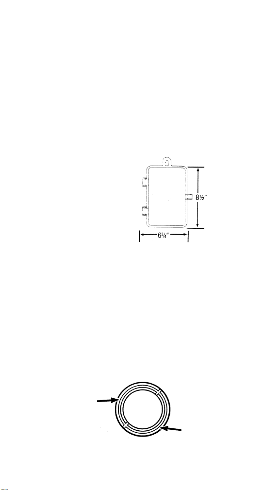
2.Mount case in a vertical position using mounting holes pro-
vided (see Figure 1).
3.Replace control into case by sliding control under tabs at
the top of the case. Push down and clips snap into place.
Figure 1.
Dimensions of EC74/50S
Conduit Connections:
1.Remove desired center knockouts by placing screwdrivers
on inner ring groove by the arrow (see figure 2), then carefully apply a solid rap on the handle of the screwdriver with
hand or hammer.
2.Remove outer ring, if necessary, by placing screwdriver
into groove by the arrow (see figure 2) and punch inward.
Smooth the opening's rim with round file or knife.
3.Attach conduit connector first to the conduit, then attach
the conduit connector to the knockout hole using the connector lock nut. To prevent unnecessary stress on enclosure walls, conduit should be aligned and supported.
Wiring:
Figure 2. Knockouts
3
Page 4
1.Wire 24, 120 or 240 Vac to input terminals, depending on
the model selected. Terminals can accommodate 12 to 24
AWG wire. CAUTION: Damage will occur to unit if incorrect
voltage is applied. Application of incorrect input voltage will
void warranty.
2.Connect output wiring as required for the particular appli-
cation.
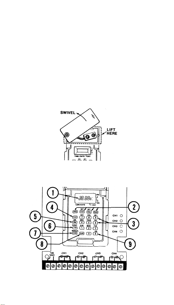
3.Install a 9V alkaline battery (not provided). Remove battery
cover. See Figure 3 below. Snap battery into battery clip.
Replace battery cover.
4.Maintenance-The EC74/50S has been carefully engineered
for reliability and safety; therefore, the only maintenance
required is to replace the 9V battery approximately every
two years. A battery log is provided to write down battery
replacement dates. Do not use any type of cleaning agent
on the liquid crystal display or the front panel.
Figure 3. Battery Cover
IV. CONTROL DESCRIPTION
Figure 4. Front Panel
4
Page 5

Front Panel
1.Time/Date Indicator-Displays hours and minutes in 12/24
hour format (for example, 00:00=midnight, 12:00=noon) or
month and date for current day or an event being programmed or revised.
Day of Week Indicator-Displays current day of week or
day being programmed. (Sunday=1, Monday=2,
Saturday=7)
2.Mode Keys-PRG (program), CLK (clock), HOL (holiday),
RUN used to select mode of operation.
3.Number/Day Keys-Used to select circuit number, and set
or program time, day, date and year.
4.Clear Key-Must be used to clear an old entry before a new
one may be entered and to clear keying errors.
5.AM/PM Key-Used to select 12-hour clock format and AM
or PM in program and clock modes.
6.Event TYP (type) Key-Used to select ON, OFF, or momen-
tary event type.
7.Manual OVR (override) Key-Used to toggle relay state
until next event.
8.DUR (duration) Key-Used to program length of momen-
tary pulses.
9.E (enter) Key-Used to enter a new set point and advances
to allow review of program.
V. PROGRAMMING INSTRUCTIONS
The EC74/50S is easy to program. The sequence outlined
here is the logical order of programming. First, you will want
to program the time-of-day, day of week, date, and year.
Then you can program set points according to your application (refer to Application Examples, Section VI for sample
programming). You program the start time of the set point
only, and you do not program the stop time. The starting of
the next programmed set point terminates the present set
point.
For your convenience, the control can be programmed without line power by using battery carryover. Relays, however,
will not operate without line power.
5
Page 6

NOTES:
1.When the unit is first powered, the display will show “24
Hr.” Press the Enter key to select 24 hour format. Press the
AM/PM key to select 12 hour format. (The display will
change to midnight on Sunday with the period flashing.)
2.The unit's memory can be cleared by disconnecting line
voltage and carryover battery.
3.For relay state to change, time must run through the set
point starting time (for example, programming an 8:00 a.m.
start time when it is already 9:00 a.m. will not change relay
state); use override to change state immediately.
4.A zero must precede the hours, minutes, month and dates
which are less than ten (Example-04/01 is April 1st).
5.The day of week is displayed as follows: 1=Sunday,
2=Monday, 3=Tuesday, 4=Wednesday, 5=Thursday,
6=Friday, 7=Saturday, and 8=Holiday.
6.In all programming modes, if a keying error is made, press
CLR then reprogram entire sequence of number keys.
7. 24-Hour Clock Time 12-Hour Clock Time
0:00 12:00 AM (Midnight)
1:00 1:00 AM
2:00 2:00 AM
3:00 3:00 AM
4:00 4:00 AM
5:00 5:00 AM
6:00 6:00 AM
7:00 7:00 AM
8:00 8:00 AM
9:00 9:00 AM
10:00 10:00 AM
11:00 11:00 AM
12:00 12:00 PM (Noon)
13:00 1:00 PM
14:00 2:00 PM
15:00 3:00 PM
16:00 4:00 PM
17:00 5:00 PM
18:00 6:00 PM
19:00 7:00 PM
20:00 8:00 PM
21:00 9:00 PM
22:00 10:00 PM
23:00 11:00 PM
6
Page 7

A. To Program Time, Day Of Week, Date, Year, And
Daylight-Saving Time
NOTE: If in 12-hour clock format, P.M. is signified by a dash
at the upper right of the display.
Step Key Description
1 CLK Time and day of week on display vanish and
dashes appear for each digit.
2 #### Key in time and day of week. If in 12-hour clock
format, and in PM hours, press PM key; dash
will appear at far right of display.
3 E Enters time and day of week. Default date of
January 1 appears.
4 CLR Date vanishes and dashes appear for each digit.
5 #### Key in date. (Month is first and day is second in
both 12-hour and 24-hour mode.)
6 E Date is entered. Latest or default year is dis-
played.
7 CLR Clears year.
8 ## Key in current year. Two keys must be pressed
(i.e., “87”).
9 E Enters year. “SPr” appears (spring daylight-sav-
ing time).
10 ### Key in date (month/day) of spring daylight-sav-
ing time, if desired. (If not desired, proceed with
step 11.)
11 E Enters spring date. “FaLL” appears (fall day-
light-saving time.)
12 #### Key in date of fall daylight-saving time, if
desired. (If not desired, proceed with step 13.)
13 E Enters fall date. Control returns to RUN mode.
B. To Review Date, Year, and Daylight-Saving Time
Step Key Description
1 CLK Dashes appear for time and day of week.
2 E Month and day appear.
3 E Year appears.
4 E Date of spring daylight-saving time appears.
5 E Date of fall standard daylight time appears.
7
Page 8

C. To Program Set Points
The EC74/50S offer three event choices: ON, OFF, or pulse
(momentary contact) event. The EC74/50S has 50 set points
assignable to any or all of the four channels.
NOTES:
1.A set point can be assigned to any single day or to any
combination of days.
2.Programming a set point involves two stages: the first
screen displays circuit (channel) number to be programmed
and the second screen displays event type.
3.The “E” key serves as a forward advance key. The “9”
serves as a reverse key.
Step Key Description
1 PRG “cir” for first event is displayed, if no previous
set points have been programmed (press E key
to advance past previous programming.)
2 1, 2, 3 Key in circuit number.
or 4
3 E Enters circuit number; “--.-- -” appears.
4 #### Key in time of event (and A.M./P.M. if neces-
sary).
5 # Key in day(s) of week and holiday if desired. If
more than one day is desired, key in additional
days. (Days programmed will flash on display in
sequence.)
NOTE: A day already entered can be removed by pressing
the number key representing that day.
6 TYP Select a single event type. Press once and a
dash appears on the lower right of the display
selecting an ON event. Press TYP key a second
time to remove dash from lower right of display
selecting an OFF event. Press TYP key a third
time and a flashing dash appears on the lower
right of display selecting a pulse (momentary
contact) event.
7 E Enters set point.
Repeat steps 2-7 for other set points.
8 RUN Exits programming mode.
8
Page 9

D. To Review Set Points
NOTE: Remember that by using the 9 key you can review set
points in reverse order. For instance, if you have programmed
all 50 set points and wish to review set point number 50,
instead of pressing E fifty times, press 9 once to review it.
Step Key Description
1 PRG Circuit number for set point number one is dis-
played.
2 E Time of day, day of week, and event type for set
point number one in channel one are displayed.
3 E Circuit number for set point number two is dis-
played.
4 E Time of day, day of week, and event type for set
point number two are displayed.
Repeat steps 3 and 4 to review remaining set points in all
four channels, until “cir” only appears (indicating no more set
points are programmed.)
5 RUN Exits programming mode.
E. To Program Pulse (Momentary) Duration
NOTE: A duration must be assigned to each circuit (channel)
having a momentary event.
Step Key Description
1 DUR Duration is displayed for circuit 1 (i.e., “01”; one
second is the default). Circuit number appears
in the lower right of display.
2 CLR Duration vanishes and two dashes appear.
3 ## Key in desired pulse duration in seconds for cir-
cuit 1.
4 E Enters duration. Duration for circuit 2 is dis-
played.
Repeat steps 2-4 for circuits 2, 3 and 4.
5 RUN Exits pulse duration mode.
9
Page 10

F. To Review Pulse Duration
Step Key Description
1 DUR Duration is displayed for circuit 1.
2 E Duration is displayed for circuit 2.
Repeat step 2 for remaining channels.
3 RUN Exits review.
G. To Initiate Manual Override
NOTE: Program can be overridden temporarily or until the
next set point. If not toggled back out of override, override
will stay in effect until next set point. When circuit (channel) is
overridden, LED changes status.
Step Key Description
1 OVR “cir” is displayed.
2 1, 2, 3 Override takes effect immediately.
or 4
Repeat steps 1 and 2 to return to initial state, if desired.
3 RUN Exits review.
H. To Program Holiday
NOTES:
1.On programmed holidays, the special holiday schedule for
each of the four circuits applies.
2.For a single day holiday, program the end month/day the
same as the start month/day.
3.The E key is a forward advance key.
4.The EC74/50S has 16 holidays. Holidays may be one day
or a holiday interval may be up to 366 days. The start and
end dates need not be in the same calendar year. A multiple day holiday counts as a single holiday.
Step Key Description
1 HOL “H.01s” (holiday #1 start) is displayed.
2 #### Key in holiday start date (month/day).
3 E Enters start date and “H.01E” (holiday #1 end) is
displayed.
4 #### Key in holiday end date.
5 E Enters end date and “H.02s” is displayed.
Repeat steps 2-5 for additional holiday durations.
6 RUN Exits holiday mode.
10
Page 11

I. To Review Holiday Dates
Step Key Description
1 HOL Holiday #1 start date appears.
2 E Holiday #1 end date appears.
Repeat step 2 for other holiday dates.
3 RUN Exits holiday mode.
VI. APPLICATION EXAMPLES
A. Indoor Lighting
Figure 5. EC74/50S Wiring Diagram for Lighting
Objective: To control indoor lighting schedules.
Suppose you want to turn ON the lights at 7:00 A.M. and turn
them OFF at 3:00 P.M. each weekday using channel 1.
Suppose also that you want the lights left OFF on two holidays: Independence Day (July 4, a one-day holiday) and
Christmas (December 24 and 25, a two-day holiday).
Step Key Description
1 PRG “cir” is displayed (if no set points were previous-
ly programmed).
2 1 Key in circuit number.
3 E Enters circuit number.
4 0, 7, Key in time for ON event.
0, 0
5 2, 3, 4, Key in each weekday (display continues to roll
5, 6 through each number selected).
11
Page 12

Step Key Description
6 TYP Press key once; a dash appears on the lower
right of display indicating an ON event.
7 E Enters set point. “cir” is displayed.
8 1 Key in circuit number.
9 E Enters circuit number.
10 0, 3, Key in time for OFF event.
0, 0
11 PM Dash appears on the upper right of display indi-
cating P.M.
12 2, 3, 4, Key in each weekday.
5, 6
13 TYP Press key twice; dash vanishes from lower right
of display indicating an OFF event.
14 E Enters set point.
15 RUN Exits programming mode.
16 HOL “H.01s” (holiday #1 start) is displayed unless
other holidays have been previously pro-
grammed.
17 0, 7, Key in first holiday start date (07/04 for July 4).
0, 4
18 E Enters start date; “H.01E” (holiday #1 end) is
displayed.
19 0, 7, Key in first holiday end date (one day holiday).
0, 4
20 E Enters end date; “H.02s” is displayed.
21 1, 2, Key in second holiday start date (12/24 for
2, 4 December 24)
22 E Enters start date: “H.02E” is displayed.
23 1, 2, Key in second holiday end date.
2, 5
24 E Enters end date (two day holiday).
25 RUN Exits programming mode.
12
Page 13
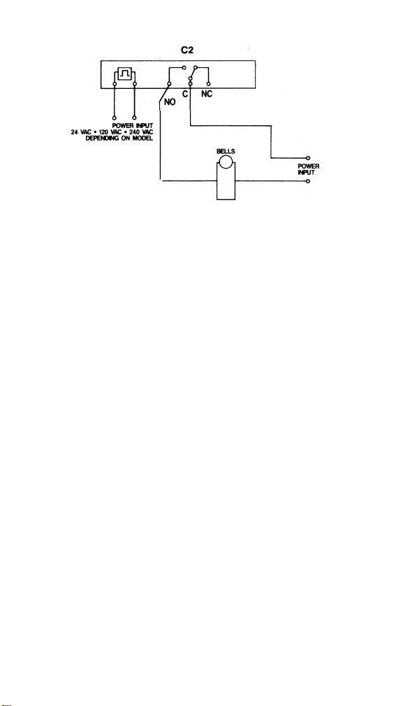
B. School Bell Application
Figure 6. School Bell Wiring Diagram.
Objective: To ring school bells for three seconds on a
preprogrammed schedule.
Using channel 2, suppose you want the bells to ring for three
seconds on the following schedule: 7:50, 8:00, 8:50, 9:00,
9:50, 10:00.
Step Key Description
1 PRG “cir” is displayed (if set points were previously
programmed, press E key until “cir” appears).
2 2 Key in circuit number.
3 E Enters circuit number.
4 0, 7, Key in time for first bell.
5, 0
5 2, 3, 4, Key in weekdays (display continues to roll
5, 6 through each number selected).
6 TYP Press this key three times; a flashing dash
appears on the lower right of display, indicating
a pulse (momentary contact) event.
7 E Enters set point.
Repeat steps 2-7, substituting 8:00, 8:50, 9:00, 9:50, and
10:00 in step 2.
8 RUN Exits programming mode; time and day dis-
played.
13
Page 14

Step Key Description
9 DUR Duration is displayed for circuit 1.
10 E Duration is displayed for circuit 2 (“01” unless
otherwise programmed).
11 CLR Clears duration; two dashes appear.
12 0, 3 Key in the number of seconds desired for pulse
duration (a leading zero is necessary).
13 E Enters pulse duration; displays duration for cir-
cuit 3.
14 RUN Exits duration mode.
C. Latching Relays on Low-Voltage Lighting Application
Figure 7. Latching Relay Wiring Diagram.
Objective: To operate latching relays turning ON and OFF
lighting.
Suppose you want to turn ON lights at 8:00 A.M. and turn
them OFF at 5:00 P.M. each week day, using channels 3 and
4 and remote latching relay or mechanical contactor.
Suppose also that you want a “sweep” to turn OFF lights at
10:00 P.M. for any lights turned ON with the remote momentary override switch (shown in the diagram above). Assume
pulse duration required for latching relay is two seconds.
NOTE: The latching relay configuration requires the use of
two channels, one to activate the latch coil, one to activate
the unlatch coil.
14
Page 15

Step Key Description
1 PRG “cir” is displayed (if no set points were previous-
ly programmed).
2 3 Key in circuit number.
3 E Enters circuit number.
4 0, 8, Key in ON time.
0, 0
5 2, 3, 4, Key in weekdays (display continues to roll
5, 6 through each number selected).
6 TYP Press key three times; a flashing dash appears
on the lower right of display indicating a pulse
event.
7 E Enters set point. “cir” is displayed.
8 4 Key in circuit number.
9 E Enters circuit number.
10 0, 5, Key in OFF time.
0, 0
11 PM Dash appears on the upper right of display indi-
cating P.M.
12 2, 3, 4, Key in weekdays.
5, 6
13 TYP Press key three times; a flashing dash appears
on the lower right of display, indicating a pulse
event.
14 E Enters set point. “cir” is displayed.
15 4 Key in circuit number for “sweep.”
16 E Enters circuit number.
17 1, 0, Key in “sweep” OFF time.
0, 0
18 PM Dash appears on the upper right of display indi-
cating P.M.
19 2, 3, 4, Key in weekdays.
5, 6
20 TYP Press key three times; a flashing dash appears
on the lower right of display, indicating a pulse
event.
21 E Enters set point.
22 RUN Exits programming mode.
23 DUR Duration is displayed for circuit 1.
24 E Press key twice to advance to circuit 3. “01 3”
is displayed.
15
Page 16

Step Key Description
25 CLR Duration vanishes and two dashes appear.
26 0, 2 Key in pulse duration of 2 seconds.
27 E Enters duration for circuit 3; advances to circuit
4. “01 4” is displayed.
28 CLR Duration vanishes and two dashes appear.
29 0, 2 Key in pulse duration of 2 seconds.
30 E Enters duration for circuit 4.
31 RUN Exits pulse duration mode.
Troubleshooting Tips
16
Problem
Nothing happens when a
setpoint occurs to turn a
load ON or OFF.
Manual override does not
work.
Clock display is locked up,
garbled, or meaningless.
Control does not operate
after programming.
Solution
• Review programmed setpoints making sure the
day has not been
skipped.
• Check input power to
control.
• Insure the clock is not in
a holiday mode (Day 8).
• Check if manual override
changes the load's state
(i.e. ON to OFF, OFF to
ON). If it does not see
next problem/solution.
• Check the load for proper
wiring. Remember, the
EC74/50S contacts
switch only what is
applied to them. (Dry or
isolated contacts.)
• Disconnect battery and
input power to the control for 1 minute. Reapply power and reprogram.
• If programming was performed (changing clock
time or entering a setpoint) the control will not
update itself. Override
the desired circuit until
the next setpoint.
Page 17

17
MAPLE CHASE COMPANY PRODUCT WARRANTY
The products manufactured by Maple Chase Company are
warranted to be free from defects in workmanship or material
under normal use and service, for a period of one (1) year
from date of purchase by the user.
Maple Chase Company's obligation under this Warranty is
limited to replacing, at one of its Authorized Service Centers,
any part or parts of a product which shall, within the time
limit set forth above, be received at one of Maple Chase
Company's Authorized Service Centers with transportation
charges prepaid, providing that Maple Chase Company's
examination discloses to its satisfaction that such part or
parts are defective.
Any adjustment or replacement of defective parts made
under this Warranty does not void the Warranty; nor does it
extend the original Warranty period.
The Warranty shall not extend to any Maple Chase Company
product which has been tampered with or repaired by other
than an Authorized Service Center of Maple Chase Company
or at its factory, nor to any product which has been subject to
misuse, neglect, accident or damage, or which has not been
properly installed and tested in operation.
Under no circumstances shall Maple Chase Company be
liable to purchaser or any third party for any loss of profits or
other direct or indirect costs, expenses, losses or consequential damages arising out of or as a result of any defects
in or failure of its products or any part or parts thereof.
THIS WARRANTY IS IN LIEU OF ANY OTHER WARRANTY.
EITHER EXPRESSED OR IMPLIED, AS TO DESCRIPTION,
QUALITY MERCHANTABILITY, FITNESS FOR ANY PARTICULAR PURPOSE OR SUE, OR ANY OTHER MATTER.
PRODUCT IMPROVEMENTS
Maple Chase Company Electric Company, Inc. reserves the
right under its product improvement policy to change construction or design details without obligation regarding previous models, and furnish equipment when so altered without
reference to illustrations or specifications used herein.
Page 18

110-699
Maple Chase Company
2820 Thatcher Road
Downers Grove, Illinois 60515
Made in Mexico
Telephone + 1 800 732 8400
ISO 9002 registered
An Invensys company
 Loading...