

Page 1
DOC-FW511-UM-R1.2
INSTALLATION MANUAL
© 2016. MAPLE ARMOR FIRE ALARM DEVICE CO., LTD.
8866, boulevard du Quartier, Brossard, Quebec, Canada, J4Y 0R2
All rights reserved. www.maplearmor.com
Page 1 of 2
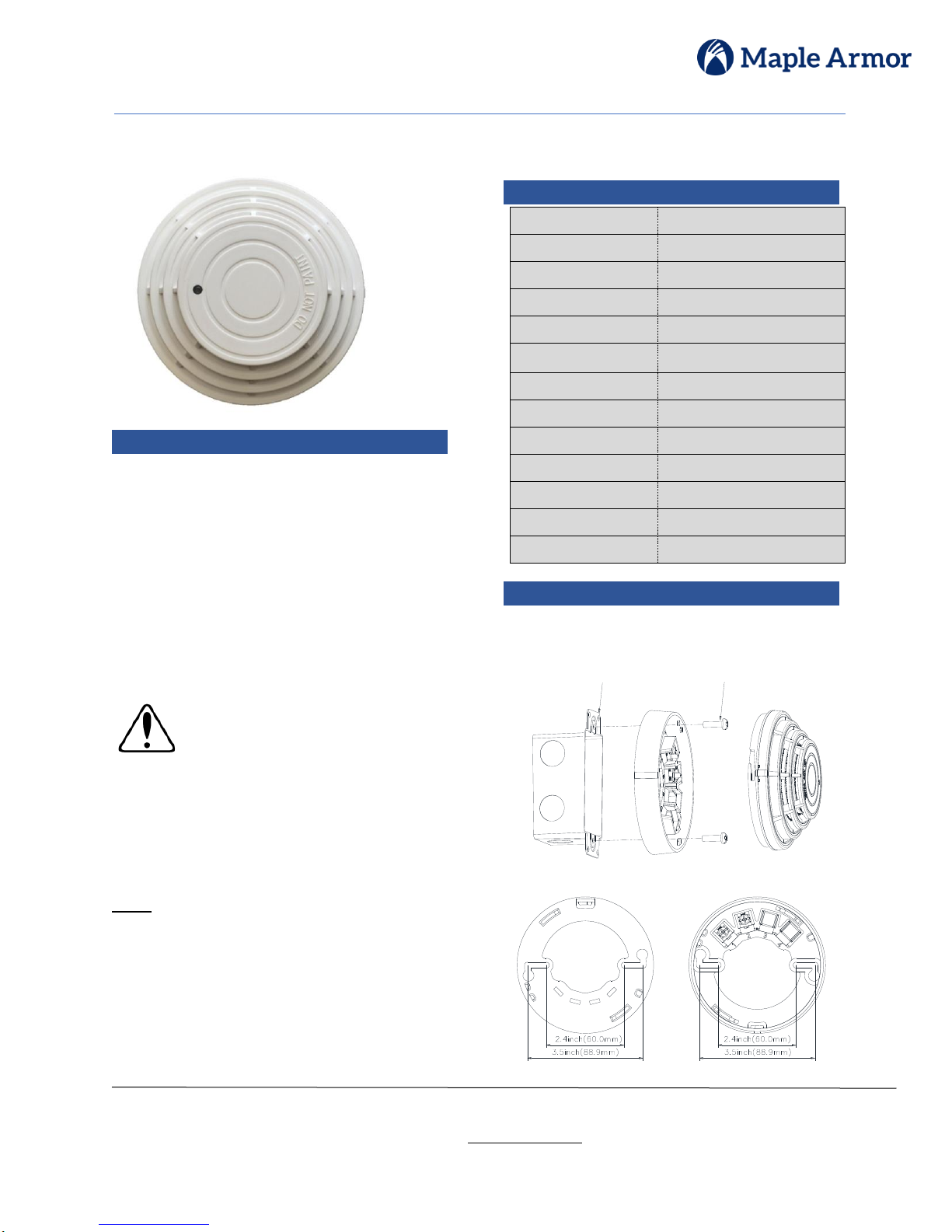
FW511 Smoke Detector
DESCRIPTION
The FW511 is an intelligent Smoke Detector used with the
FW500 Detector Base, is a UL listed component according
to UL 268 and ULC-S529 for Fire Protective Signaling
Systems for indoor use. It features a slim design which
combines visual appeal with a high standard of reliability. It
responds quickly and dependably to a broad range of fires.
The detector has a Microcontroller Unit (MCU), performing
comprehensive self-diagnostic tests and result analysis. The
FW511 is intelligent, addressable, and takes one address on
the Signaling Line Circuit (SLC) of the fire alarm control
panel.
ATTENTION
The products must be installed in accordance with NFPA 72,
CAN/ULC-S524, and/or Canadian Electrical
Code depending on country of installation.
Check information of equipment used in the
system by other manufacturers for any
guidelines or restrictions.
The detector should never be installed in the
following locations: areas with excessive exhaust
fumes, kitchen areas, near fireplaces, furnace rooms,
etc. Smoke detectors are not to be used with detector
guards unless the combination has been evaluated
and found suitable for that purpose.
NOTE
Do not paint this device.
Any material extrapolated from this document or from
Maple Armor’s instructions or other documents describing
the product for use in promotional or advertising claims, or
for any other use, including description of the product’s
application, operation, installation, and testing is the sole
responsibility of the user. Maple Armor will not assume any
liability for such use. In no case will Maple Armor’s liability
exceed the purchase price paid for a product.
SPECIFICATION
Nominal Voltage
24VDC
Voltage Range
17.6 to 25.5VDC
Standby Current
0.14mA
Alarm Current
1mA
Smoke Sensitivity
1.6% ft to2.3% ft
Operating
Temperature
32°F to 100°F (0°C to 38°C)
Operating Humidity
0% to 93% RH
Diameter
4.13 in. (105mm)
Height (with base)
1.87 in. (47.5 mm)
Weight (with base)
4.6 oz (132 g)
Mounting
FW500 Base
Mounting Orientation
Ceiling, wall
Spacing
30 feet (9.1 m)
SPECIFICATIONS
INSTALLATION
1. Mount the FW500 base onto a 2x4’’ electrical
box using the screws provided, see Figure 1. The
installation hole pitch is illustrated in Figure 2.
Figure 1. FW500 Base Installation
Figure 2. Wiring Terminals and Pitch of Hole
#6-32 Screw(2)
For 2X4" Electrical Box
2X4" Electrical Box
Page 2
DOC-FW511-UM-R1.2
INSTALLATION MANUAL
© 2016. MAPLE ARMOR FIRE ALARM DEVICE CO., LTD.
8866, boulevard du Quartier, Brossard, Quebec, Canada, J4Y 0R2
All rights reserved. www.maplearmor.com
Page 2 of 2
INSTALLATION, Continued
2. Wire the SLC to the detector base, as illustrated in
Figure 3. There is no polarity distinction between
terminal 1 and terminal 2.
LA+
LA-
LB+
LB-
FACP
ALU
FW500
FW500
1
2
3
4
1
2
3
4
1
2
3
4
FW500
(a) Class A Circuit
LA+
LALB+
LB-
ALU
FACP
FW500
FW500
1
2
3
4
1
2
3
4
1
2
3
4
FW500
(b) Class B Circuit
Figure 3. Wiring Diagram
3. Set the detector address (1-252). Use the hand-
held Programmer ReadWritor FW411. Refer to
the FW411 Manual.
4. Put the detector onto it’s base and secure it into
position by turning clockwise.
5. Apply power to the control unit to activate the
SLC.
TESTING
1. Before testing, inform the proper authorities that
the system is undergoing maintenance and will
temporarily be put out of service. Disable the
system to prevent unwanted alarms.
2. Make sure the indicator LED on the detector’s
surface is flashing. Failure to flash indicates a nonfunctioning detector or a faulty wiring. Check the
wiring and remount the detector.
3. Go/No Go Field Test: Use the aerosol, Solo A4.
The LED on FW511 should latch steady-on and the
system should go into alarm.
4. Once the testing is completed, set the system back
to normal operation and inform proper authorities.
MAINTENANCE
The detector needs to be tested on a regular basis.
Refer to the Testing section for more information
about the procedure. The detector has an automaticdrift-compensation feature to provide accuratesensitivity detection. When the drift is out of range,
the “Init.Dev_Bad” trouble will be displayed on the
FACP, which means the sensitivity may be outside
the limits and the detector needs cleaning.
1. Before cleaning, notify the proper authorities that
the system is undergoing maintenance and will be
temporarily out of service.
2. Disable the system to prevent unwanted alarms.
3. Remove the detector to be cleaned from the
system.
4. Remove the detector cover and the maze cover.
5. Use a vacuum cleaner or compressed air to
remove dust and debris from the maze.
6. Reinstall the detector.
7. Test the detector as described in the Testing
section.
8. Notify the proper authorities that the system is
back on line.
Figure 4. Cleaning
 Loading...