

Page 1
DE
EN
Montage- und Betriebsanleitung | Installation and Operating Instructions
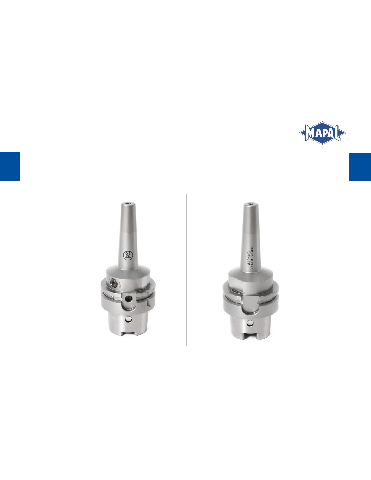
HIGHTORQUE CHUCK HTC MIT SCHLANKER KONTUR
HTC HIGHTORQUE CHUCK WITH SLENDER CONTOUR
Page 2

Page 3

Montage- und Betriebsanleitung
Installation and Operating Instructions
3
DE
Inhaltsverzeichnis
Ziel der Montage- und Betriebsanleitung ................................................................................................................................. 4
1
Kontakt ............................................................................................................................................................................................... 4
2
Sicherheit ........................................................................................................................................................................................... 5
3
3.1 Zielgruppe ........................................................................................................................................................................................................................................... 5
3.2 Bestimmungsgemäße Verwendung ............................................................................................................................................................................................. 5
3.3 Nicht bestimmungsgemäße Verwendung .................................................................................................................................................................................. 5
3.4 Gewährleistung ................................................................................................................................................................................................................................. 6
3.5 Allgemeine Warn- und Sicherheitshinweise ............................................................................................................................................................................. 6
3.6 Warnungen und Symbole auf dem Hydrodehnspannfutter ................................................................................................................................................ 11
Allgemeine Informationen ........................................................................................................................................................... 13
4
4.1 Darstellung eines HTC mit schlanker Kontur .......................................................................................................................................................................... 13
4.2 Beschriftung der Betätigungselemente ................................................................................................................................................................................... 14
4.3 Benötigte Werkzeuge, Hilfs- und Betriebsstoffe ................................................................................................................................................................... 15
4.4 Technische Daten ........................................................................................................................................................................................................................... 16
4.5 Prüfung der Spannkraft ............................................................................................................................................................................................................... 19
Bedienung des HTC mit schlanker Kontur ............................................................................................................................... 20
5
5.1 Spannen eines Werkzeugs ........................................................................................................................................................................................................... 20
5.2 Entspannen eines Werkzeugs ..................................................................................................................................................................................................... 24
5.3 Maschinenseitige Anpassung der Kühlmittelzuführung nach Form AD/AF ................................................................................................................... 25
Pflege und Wartung ...................................................................................................................................................................... 31
6
Entsorgung ....................................................................................................................................................................................... 31
7
Table of contents ....................................................................................................................................................................................... 33
Page 4

4
Montage- und Betriebsanleitung
Installation and Operating Instructions
DE
Ziel der Montage- und Betriebsanleitung
1
Die vorliegende Montage- und Betriebsanleitung beschreibt die richtige Bedienung des HighTorque Chuck HTC mit
schlanker Kontur und axialer Werkzeuglängeneinstellung (nachfolgend als „Hydrodehnspannfutter“ bezeichnet). Im Detail
erhalten Sie Informationen, wie Sie ein Werkzeug mit dem Hydrodehnspannfutter spannen und entspannen können. Zusätzlich werden die wichtigsten Sicherheitshinweise beim Umgang mit dem Hydrodehnspannfutter erläutert.
Nachfolgend erhalten Sie in Kapitel 5 eine detaillierte Beschreibung der einzelnen Funktionen und Handlungsschritte, die
zum erfolgreichen Spannen und Entspannen von Werkzeugen mit dem Hydrodehnspannfutter notwendig sind.
Die Montage- und Betriebsanleitung ist Bestandteil des Hydrodehnspannfutters und muss in unmittelbarer Nähe des Hydrodehnspannfutters für das Personal jederzeit zugänglich aufbewahrt werden. Grundvoraussetzung für sicheres Arbeiten ist
die Einhaltung aller angegebenen Sicherheitshinweise und Handlungsanweisungen in dieser Montage- und Betriebsanleitung.
Darüber hinaus gelten die örtlichen Arbeitsschutzvorschriften und allgemeinen Sicherheitsbestimmungen für den Einsatzbereich des Hydrodehnspannfutters. Abbildungen in dieser Montage- und Betriebsanleitung dienen dem grundsätzlichen Verständnis und können von der tatsächlichen Ausführung abweichen.
Kontakt
2
MAPAL Fabrik für Präzisionswerkzeuge Dr. Kress KG
Adresse
Obere Bahnstraße 13
D-73431 Aalen
Telefon
+49 (0) 7361 585-0
Fax
+49 (0) 7361 585-1029
E-Mail
Internet
www.mapal.com
Page 5

Montage- und Betriebsanleitung
Installation and Operating Instructions
5
DE
Sicherheit
3
3.1 Zielgruppe
Die Bedienung des Hydrodehnspannfutters darf nur durch ausgebildetes, autorisiertes und zuverlässiges Fachpersonal
erfolgen. Das Fachpersonal muss Gefahren erkennen und vermeiden können und muss hierzu dieses Dokument vor der Verwendung des Hydrodehnspannfutters gelesen und verstanden haben.
Die Unfallverhütungsvorschriften, Sicherheitsbestimmungen und -vorschriften des Maschinenherstellers sind dem Fachpersonal bekannt und vom Fachpersonal bei der Bedienung des Hydrodehnspannfutters zu beachten und einzuhalten.
3.2 Bestimmungsgemäße Verwendung
Das Hydrodehnspannfutter dient ausschließlich zum Aufnehmen und Spannen von Werkzeugen auf Maschinen für die
Zerspanung in industrieller Anwendung.
Das Hydrodehnspannfutter ist speziell zum hydraulischen Spannen von rotierenden Werkzeugen auf Werkzeugmaschinen
für manuellen und automatischen Werkzeugwechsel konzipiert.
Das Hydrodehnspannfutter darf nur verwendet werden, wenn die Einhaltung aller Angaben dieser Montage- und Be-
triebsanleitung gewährleistet ist.
Das Abweichen der Vorschriften kann zu Verletzungen oder Beschädigungen von Maschinen und Zubehör führen, für die
MAPAL keine Haftung übernimmt.
3.3 Nicht bestimmungsgemäße Verwendung
Das Hydrodehnspannfutter darf nur entsprechend der technischen Daten eingesetzt werden (siehe Kapitel 4.4).
Das Hydrodehnspannfutter darf nicht auf einem Schrumpfgerät erwärmt werden. Es ist nicht für den Schrumpfprozess
und den dabei vorkommenden Temperaturen ausgelegt.
Das Hydrodehnspannfutter darf nicht für die Werkstückspannung eingesetzt werden.
Das Hydrodehnspannfutter darf nicht verändert und für andere Anwendungen erschlossen werden.
Zusätzliche Bohrungen, Gewinde und Anbauten dürfen nur nach schriftlicher Genehmigung durch MAPAL angebracht
werden.
Page 6

6
Montage- und Betriebsanleitung
Installation and Operating Instructions
DE
Im Falle von eigenmächtigen Veränderungen am Hydrodehnspannfutter oder einer nicht bestimmungsgemäßen Verwen-
dung des Hydrodehnspannfutters, erlischt der Gewährleistungsanspruch gegenüber MAPAL.
Für Schäden aus einer nicht bestimmungsgemäßen Verwendung haftet der Hersteller nicht.
3.4 Gewährleistung
Die Gewährleistung gilt für einen Zeitraum von 24 Monaten und beginnt mit dem Lieferdatum ab Werk bei bestimmungsgemäßer Verwendung und unter Einhaltung der Inhalte der Montage- und Betriebsanleitung. Die Gewährleistung beschränkt sich auf den 1-Schicht-Betrieb.
Das Hydrodehnspannfutter inklusive all seiner Komponenten und Zubehörteile darf nicht verändert und für unbefugte Anwendungen erschlossen werden. Jegliche Veränderung des Hydrodehnspannfutters oder unbefugte Verwendung führt zum
Erlöschen des Gewährleistungsanspruchs gegenüber MAPAL.
MAPAL lehnt ausdrücklich jegliche Haftung für Schäden durch schadhafte Werkzeuge oder schadhafte Maschinenteile ab.
Verschleißteile unterliegen nicht der Gewährleistung.
3.5 Allgemeine Warn- und Sicherheitshinweise
WARNUNG
Gefahr durch unausgebildetes und unautorisiertes Personal!
Das Spannen von Werkzeugen und Einbringen in eine Werkzeugmaschine kann durch unausgebildetes und unautorisier-
tes Personal zu gefährlichen Situationen führen.
Ausschließlich ausgebildetes, autorisiertes und zuverlässiges Fachpersonal darf Werkzeuge spannen und in eine
Werkzeugmaschine einbringen.
Die technischen Daten der Maschinenschnittstelle sind vom Fachpersonal zu beachten.
Das Fachpersonal muss Gefahren erkennen und vermeiden können.
Page 7
Montage- und Betriebsanleitung
Installation and Operating Instructions
7
DE
WARNUNG
Missachten der technischen Daten oder Fehlbedienung!
Das Missachten der technischen Daten oder eine Fehlbedienung kann zu schweren Verletzungen des Bedieners und zu
Sachschaden führen.
Die technischen Daten und deren Einhaltung in Kapitel 4.4 beachten.
Beim Spannvorgang die Spannschraube bis zum Anschlag unter Einhaltung der Mindestumdrehungen eindrehen.
Die vorgeschriebenen Werte der Mindesteinspanntiefe einhalten.
Die vorgeschriebenen Grenzdrehzahlen der maschinenseitigen Schnittstelle einhalten.
Die Grenzbelastbarkeit der maschinenseitigen Schnittstelle nach zum Beispiel VDMA 34181 beachten.
Treten Unregelmäßigkeiten während der Bedienung auf, das Hydrodehnspannfutter aus Sicherheitsgründen nicht
mehr einsetzen und zur Überprüfung oder zur Reparatur an MAPAL senden.
3.5.1 Gefahren durch Hitze- und Wärmeentwicklung
WARNUNG
Schrumpfen oder Erhitzen des Hydrodehnspannfutters kann zu Verletzungen führen und Maschinen und Zubehör beschädigen!
Durch Schrumpfen oder Erhitzen kann sich das Hydrodehnspannfutter verformen oder explosionsartig platzen.
Dabei können heißes Öl, Öldämpfe und Metallsplitter geschossartig umherfliegen und zu schweren Verletzungen des Bedieners führen und Maschinen und Zubehör beschädigen.
Das Hydrodehnspannfutter nicht schrumpfen oder über die angegebene Betriebstemperatur erhitzen.
Page 8
8
Montage- und Betriebsanleitung
Installation and Operating Instructions
DE
WARNUNG
Entspannen bei zu hoher Spannfuttertemperatur!
Durch das Entspannen bei zu hoher Spannfuttertemperatur können sich Teile des Hydrodehnspannfutters geschossartig
lösen und heißes Öl austreten. Dies kann zu schweren Verletzungen führen und Maschinen und Zubehör beschädigen.
Die Spannschraube des Hydrodehnspannfutters ausschließlich bei Raumtemperatur betätigen.
HINWEIS
Spannen ohne Werkzeug!
Das Spannen ohne Werkzeug kann zur Beschädigung des Hydrodehnspannfutters führen.
Das Hydrodehnspannfutter nicht ohne Werkzeug spannen.
3.5.2 Mechanische Gefahren
WARNUNG
Spannen und Entspannen bei laufender Maschine!
Durch das Spannen und Entspannen des Hydrodehnspannfutters bei laufender Maschine können schwere Verletzungen
des Bedieners verursacht werden.
Das Hydrodehnspannfutter nur außerhalb und bei stillstehender Maschine betätigen.
Page 9

Montage- und Betriebsanleitung
Installation and Operating Instructions
9
DE
WARNUNG
Verwendung langer, auskragender und schwerer Werkzeuge oder Verlängerungen!
Bei Verwendung langer, auskragender und schwerer Werkzeuge oder beim Einsatz von Verlängerungen kann sich das
Werkzeug oder Teile der Werkzeugkombination geschossartig lösen und zu schweren Verletzungen führen.
Bei langen, auskragenden und schweren Werkzeugen oder beim Einsatz von Verlängerungen die Drehzahl gemäß den
individuellen Vorgaben und in Verantwortung des Anwenders reduzieren.
Die individuell festzulegende Maximallänge und die Wuchtgüte des Gesamtsystems auch bei Verwendung von Ver-
längerungen beachten.
Bei Sonderausführungen müssen eventuell abweichende Zeichnungsangaben berücksichtigt werden.
Die Grenzbelastbarkeit der maschinenseitigen Schnittstelle beachten.
VORSICHT
Scharfe Schneidkanten am Werkzeug!
Scharfe Schneidkanten können Schnittverletzungen verursachen.
Beim Werkzeugwechsel Schutzhandschuhe tragen.
HINWEIS
Werkzeuglängeneinstellung bei gespanntem Werkzeug!
Die Durchführung einer axialen oder radialen Werkzeuglängeneinstellung des Werkzeugs bei vollständig gespanntem
Werkzeug führt zur Beschädigung des Hydrodehnspannfutters.
Bei gespanntem Werkzeug keine Werkzeuglängeneinstellung durchführen.
Page 10

10
Montage- und Betriebsanleitung
Installation and Operating Instructions
DE
HINWEIS
Einsatz von Schäften mit Ausnehmungen!
Der Einsatz von Schäften mit Form B und E (DIN 1835) oder Schäfte mit Form HB und HE (DIN 6535) kann zu ungenau-
em Rundlauf und ungenauer Wuchtgüte des Gesamtsystems führen.
Ausschließlich Schäfte der Form A einsetzen oder das Gesamtsystem feinwuchten.
HINWEIS
Beschädigung der farblich versiegelten Entlüftungsschraube!
Bei Beschädigung der farblich versiegelten Entlüftungsschraube ist das Hydrodehnspannfutter nicht mehr funktionstüch-
tig und darf umgehend nicht mehr zum Einsatz kommen.
Nicht die farblich versiegelte Entlüftungsschraube beschädigen oder öffnen.
Bei beschädigter Entlüftungsschraube, das Hydrodehnspannfutter aus Sicherheitsgründen nicht mehr einsetzen.
Bei Beschädigung zur Überprüfung und Reparatur an MAPAL senden.
HINWEIS
Verschleiß durch maschinellen Schraubendreher beim Spannen der Spannschraube!
Der Einsatz eines maschinellen Schraubendrehers beim Spannen der Spannschraube führt zu einem erhöhten Verschleiß
des Spannsatzes.
Die Spannschraube nur manuell spannen.
Page 11
Montage- und Betriebsanleitung
Installation and Operating Instructions
11
DE
3.6 Warnungen und Symbole auf dem Hydrodehnspannfutter
WARNUNG
Schrumpfen oder Erhitzen des Hydrodehnspannfutters kann zu Verletzungen führen und Maschinen und Zubehör beschädigen!
Durch Schrumpfen oder Erhitzen kann sich das Hydrodehnspannfutter verformen oder explosionsartig platzen.
Dabei können heißes Öl, Öldämpfe und Metallsplitter geschossartig umherfliegen und zu schweren Verletzungen des Bedieners führen und Maschinen und Zubehör beschädigen.
Das Hydrodehnspannfutter nicht schrumpfen oder über die angegebene Betriebstemperatur erhitzen.
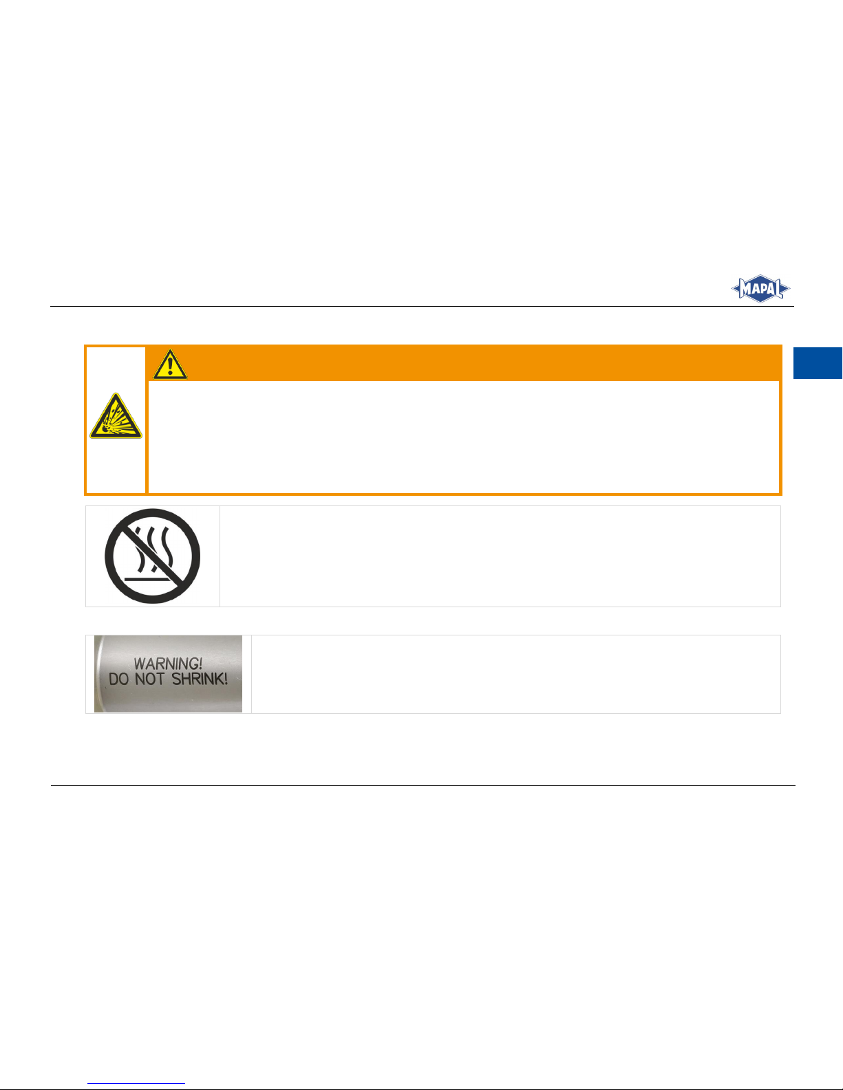
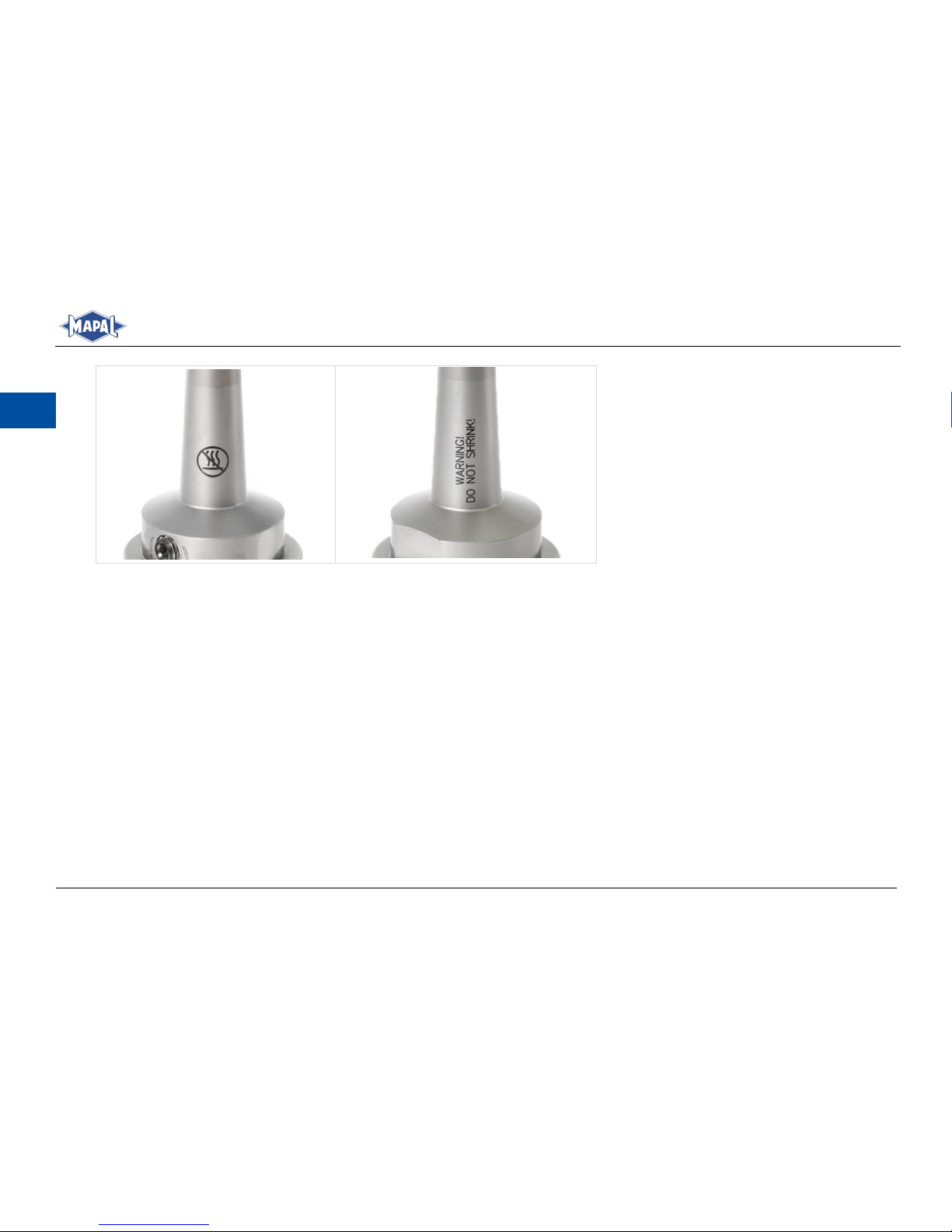
Verbotssymbol:
Das Verbotssymbol auf dem Hydrodehnspannfutter weist ausdrücklich darauf hin, das Hydrodehnspannfutter nicht zu schrumpfen oder zu erhitzen.
Verbotssymbol auf dem Hydrodehnspannfutter
Abb. 1:
Das Hydrodehnspannfutter ist mit diesem Warnhinweis beschriftet.
Warnhinweis auf dem Hydrodehnspannfutter
Abb. 2:
Page 12
12
Montage- und Betriebsanleitung
Installation and Operating Instructions
DE
Position von Verbotssymbol und Warnhinweis auf dem Hydrodehnspannfutter
Abb. 3:
Page 13
Montage- und Betriebsanleitung
Installation and Operating Instructions
13
DE
Allgemeine Informationen
4
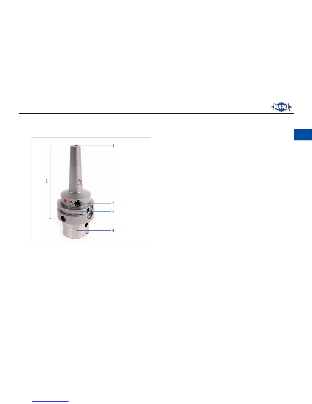
4.1 Darstellung eines HTC mit schlanker Kontur
Legende
1 | Aufnahmebohrung
2 | Spannschraube
3 | Farblich versiegelte Entlüftungsschraube
4 | Kegel des Hydrodehnspannfutters
l1 | Auskraglänge
Einzelne Komponenten des HTC mit schlanker Kontur
Abb. 4:
Page 14
14
Montage- und Betriebsanleitung
Installation and Operating Instructions
DE
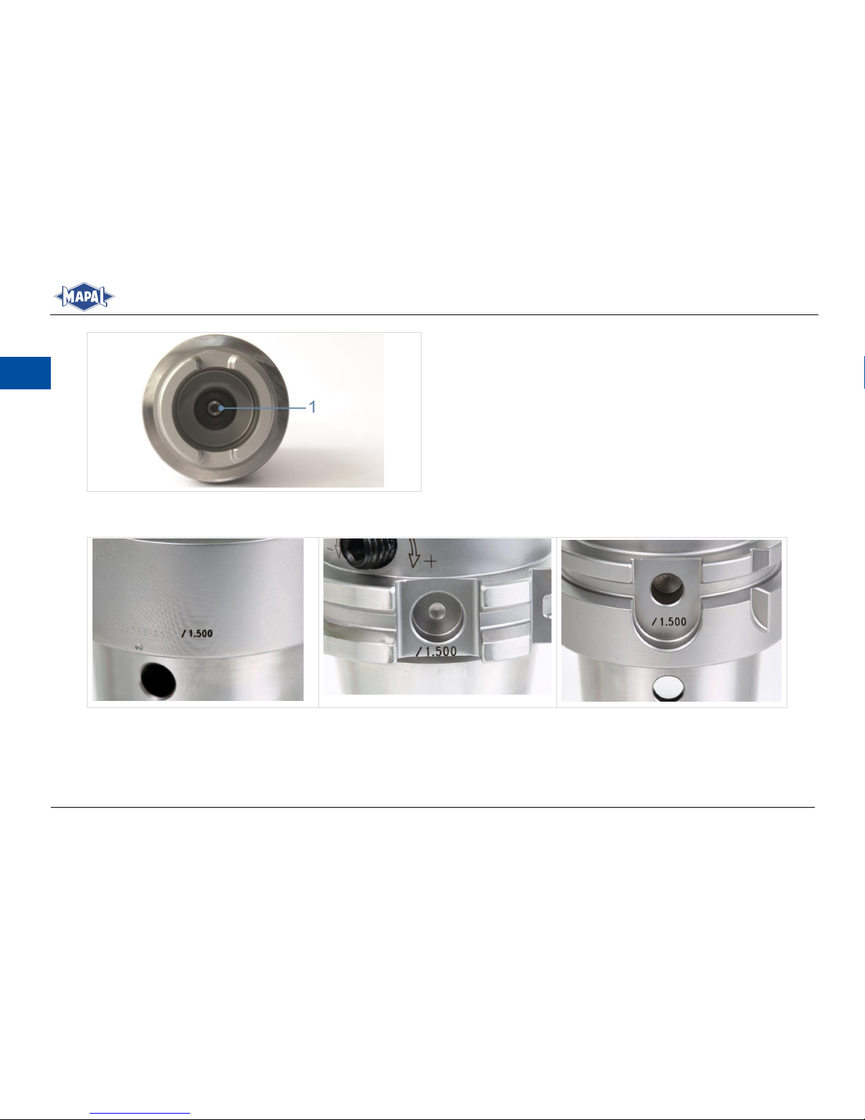
Legende
1 | Anschlagschraube zur axialen Werkzeuglängenein-
stellung
Sicht von unten auf das HTC mit schlanker Kontur
Abb. 5:
4.2 Beschriftung der Betätigungselemente
Beschriftung zur Prüfung der Spannkraft: Drei mögliche Positionen auf dem Spannfutter
Abb. 6:
Page 15
Montage- und Betriebsanleitung
Installation and Operating Instructions
15
DE
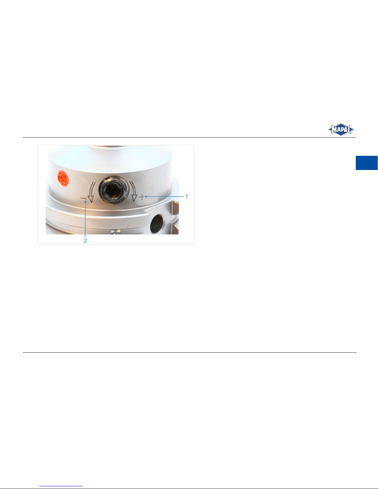
Legende
1 | + Werkzeug spannen (im Uhrzeigersinn)
2 | - Werkzeug lösen (gegen Uhrzeigersinn)
Drehrichtungsangabe zum Lösen und Spannen des Wekzeugs
Abb. 7:
4.3 Benötigte Werkzeuge, Hilfs- und Betriebsstoffe
Innensechskantschlüssel für die Anschlagschraube zur axialen Werkzeuglängeneinstellung.
Innensechskantschlüssel für die Spannschraube.
Page 16

16
Montage- und Betriebsanleitung
Installation and Operating Instructions
DE
4.4 Technische Daten
WARNUNG
Missachten der technischen Daten!
Das Missachten der technischen Daten kann zu schweren Verletzungen des Bedieners und zu Sachschaden führen.
Die technischen Daten und deren Einhaltung in Kapitel 4.4 beachten.
Beim Spannvorgang die Spannschraube bis zum Anschlag unter Einhaltung der Mindestumdrehungen eindrehen.
Die vorgeschriebenen Werte der Mindesteinspanntiefe einhalten.
Die vorgeschriebenen Grenzdrehzahlen der maschinenseitigen Schnittstelle einhalten.
Die Grenzbelastbarkeit der maschinenseitigen Schnittstelle nach zum Beispiel VDMA 34181 beachten.
Treten Unregelmäßigkeiten während der Bedienung auf, das Hydrodehnspannfutter aus Sicherheitsgründen nicht
mehr einsetzen und zur Überprüfung oder zur Reparatur an MAPAL senden.
Allgemeine technische Daten:
Werkstoff 1.600 N/mm
2
.
Härte 52+2 HRc
Halter standardmäßig gewuchtet.
Betriebstemperatur: 20 bis 120 °C.
Kühlmitteldruck maximal 80 bar.
Maximaler Verstellweg 10 mm.
Mit und ohne Reduzierhülsen können Zylinderschäfte mit Schafttoleranz h6 nach DIN 1835 Form A, B, E und nach
DIN 6535 Form HA, HB und HE gespannt werden.
Angabe zur Prüfung der Spannkraft (siehe Kapitel 4.2 und 4.5).
Page 17

Montage- und Betriebsanleitung
Installation and Operating Instructions
17
DE
Richtwerte der Grenzdrehzahlen von Hydrodehnspannfutter mit HSK-Schnittstelle
Nenngröße
HSK
Max. zulässige
Grenzdrehzahl
[min-1]
32
37.500
40
37.500
50
30.000
63
24.000
80
20.000
100
16.000
Richtwerte der Grenzdrehzahlen
Tab. 1:
Page 18

18
Montage- und Betriebsanleitung
Installation and Operating Instructions
DE
Technische Daten [mm]
Spanndurchmesser [mm]
Mindesteinspanntiefe [mm]
Zul. Übertragbares Drehmoment bei Schaft Kleinstmaß
h6 [Nm]
Max. Drehzahl [min-1]
l1 ≤ 125 mm
l1 > 125 mm
3
12
3
40.000
20.000
4
16 6 5
20
10
6
27
20
7
27
20 8 27
35 9 31
50
10
31
65
11
31
85
12
36
110
13
36
110
20.000
10.000
14
36
120
16
39
160
18
39
200
20
41
260
Technische Daten [mm]
Tab. 2:
Page 19

Montage- und Betriebsanleitung
Installation and Operating Instructions
19
DE
Technische Daten [Zoll]
Spanndurchmesser [Zoll]
Mindesteinspanntiefe [mm]
Zul. Übertragbares Drehmoment bei Schaft Kleinstmaß
h6 [Nm]
Max. Drehzahl [min-1]
l1 ≤ 125 mm
l1 > 125 mm
1/8
12
3
40.000
20.000
3/16
16
8
1/4
27
20
5/16
27
35
3/8
31
65
7/16
31
85
1/2
36
110
5/8
39
150
20.000
10.000
3/4
41
260
Technische Daten [Zoll]
Tab. 3:
4.5 Prüfung der Spannkraft
Die Mindestumdrehungen werden auf dem Hydrodehnspannfutter angegeben (siehe Kapitel 4.2) und stellen eine einfache
und zuverlässige Prüfung der Spannkraft dar. Damit wird sichergestellt, dass bei jedem Spannvorgang das zulässige übertragbare Drehmoment erreicht wird. Die Mindestumdrehungen sind die Anzahl der Umdrehungen der Spannschraube, die ab
dem Grippunkt des Schaftes bis zum Anschlag der Spannschraube erreicht werden müssen. Der Grippunkt ist die Position
der Spannschraube, bei der sich der Werkzeugschaft mit zwei Fingern nicht mehr drehen oder aus der Aufnahmebohrung
herausziehen lässt.
Page 20
20
Montage- und Betriebsanleitung
Installation and Operating Instructions
DE
Bedienung des HTC mit schlanker Kontur
5
5.1 Spannen eines Werkzeugs
INFORMATION
Die Betätigung der Anschlagschraube des Dehnspannfutters ist beidseitig möglich. Das Dehnspannfutter kann je
nach Ausführung entweder axial oder radial eingestellt werden.
WARNUNG
Schrumpfen oder Erhitzen des Hydrodehnspannfutters kann zu Verletzungen führen und Maschinen und Zubehör beschädigen!
Durch Schrumpfen oder Erhitzen kann sich das Hydrodehnspannfutter verformen oder explosionsartig platzen.
Dabei können heißes Öl, Öldämpfe und Metallsplitter geschossartig umherfliegen und zu schweren Verletzungen des Bedieners führen und Maschinen und Zubehör beschädigen.
Das Hydrodehnspannfutter nicht schrumpfen oder über die angegebene Betriebstemperatur erhitzen.
WARNUNG
Spannen und Entspannen bei laufender Maschine!
Durch das Spannen und Entspannen des Hydrodehnspannfutters bei laufender Maschine können schwere Verletzungen
des Bedieners verursacht werden.
Das Hydrodehnspannfutter nur außerhalb und bei stillstehender Maschine betätigen.
Page 21
Montage- und Betriebsanleitung
Installation and Operating Instructions
21
DE
VORSICHT
Scharfe Schneidkanten am Werkzeug!
Scharfe Schneidkanten können Schnittverletzungen verursachen.
Beim Werkzeugwechsel Schutzhandschuhe tragen.
INFORMATION
Nur unbeschädigte und gratfreie Werkzeuge spannen.
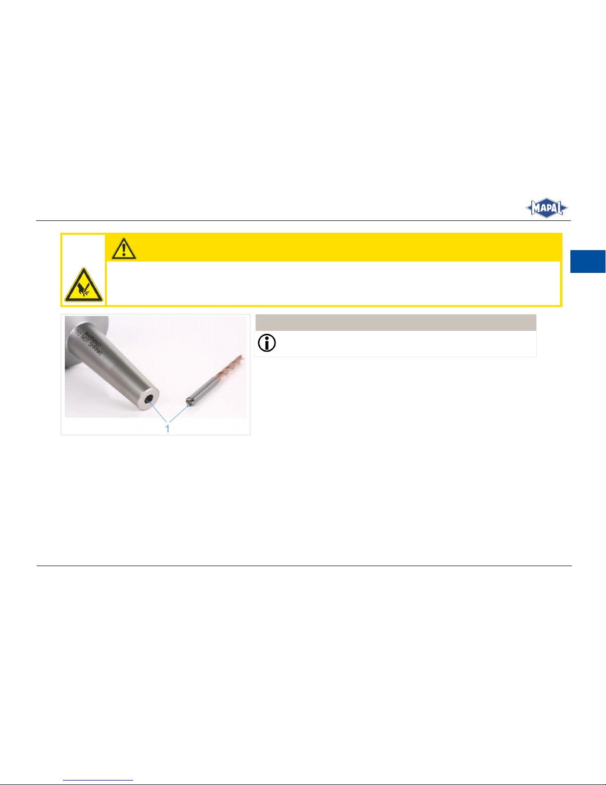
Reinigen Sie die Aufnahmebohrung und den Werkzeugschaft (1).
1.
Hydrodehnspannfutter und Werkzeug rei-
Abb. 8:
nigen
Page 22
22
Montage- und Betriebsanleitung
Installation and Operating Instructions
DE
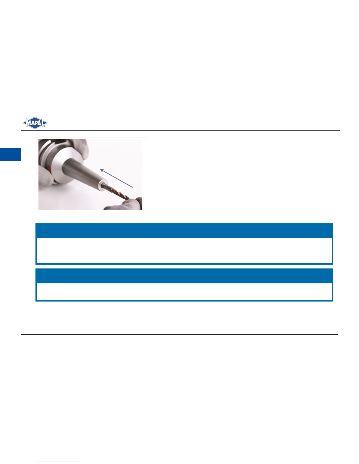
Schieben Sie das Werkzeug mit dem Schaft voraus bis zur Anschlag-
2.
schraube in die Aufnahmebohrung des Hydrodehnspannfutters.
Werkzeug einschieben
Abb. 9:
HINWEIS
Beschädigung durch Nichteinhalten der Mindesteinspanntiefe beim Hydrodehnspannfutter!
Die vorgeschriebenen Werte der Mindesteinspanntiefe einhalten (siehe Tab. 2: Technische Daten [mm] oder Tab. 3:
Technische Daten [Zoll]).
HINWEIS
Beschädigung durch Werkzeuglängeneinstellung bei gespanntem Werkzeug!
Bei gespanntem Werkzeug keine Werkzeuglängeneinstellung durchführen.
Page 23
Montage- und Betriebsanleitung
Installation and Operating Instructions
23
DE
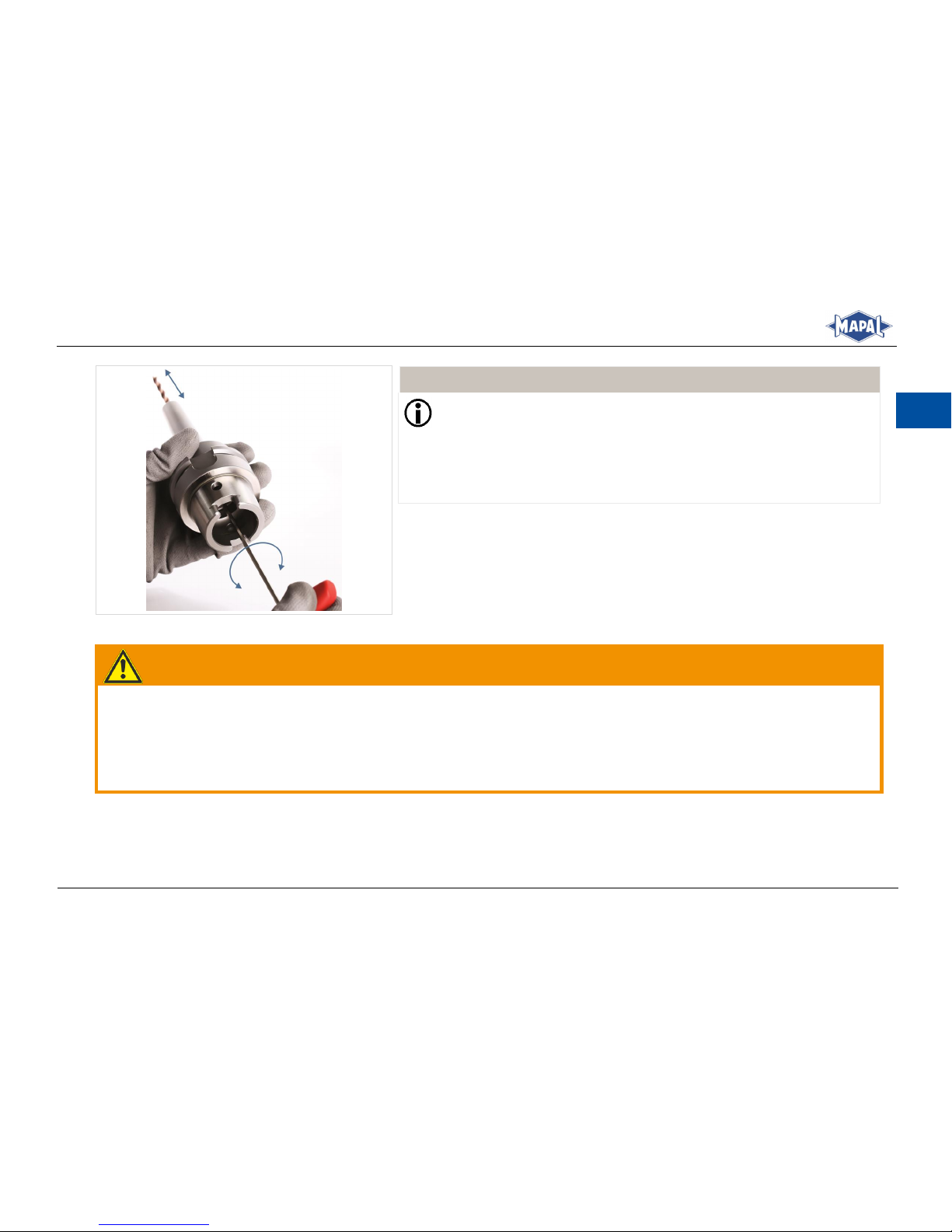
Stellen Sie das Hydrodehnspannfutter auf die Werkzeuglänge ein, hierzu
3.
drehen Sie die Anschlagschraube zur axialen Werkzeuglängeneinstellung
mit Hilfe eines passenden Innensechskantschlüssels mit Quergriff.
INFORMATION
Die Anschlagschraube zur axialen Werkzeuglängeneinstellung ist
nicht gegen Herausfallen gesichert. Der angegebene Verstellbereich
kann nicht überschritten werden.
Die Betätigung der Anschlagschraube zur axialen Werkzeuglängeneinstellung ist beidseitig möglich.
Werkzeuglänge einstellen
Abb. 10:
WARNUNG
Unzureichendes Spannen bis zum Anschlag und Nichteinhaltung der Mindestumdrehungen!
Durch unzureichendes Spannen bis zum Anschlag und Nichteinhaltung der Mindestumdrehungen kann sich das Werk-
stück geschossartig lösen und zu schweren Verletzungen führen.
Beim Spannvorgang die Spannschraube bis zum Anschlag unter der Einhaltung der Mindestumdrehungen eindrehen
(siehe Kapitel 4.4 Technische Daten).
Page 24
24
Montage- und Betriebsanleitung
Installation and Operating Instructions
DE
INFORMATION
Die Spannschraube ist gegen Herausfallen nicht gesichert!
Achten Sie darauf, dass die Spannschraube schmutzfrei ist.
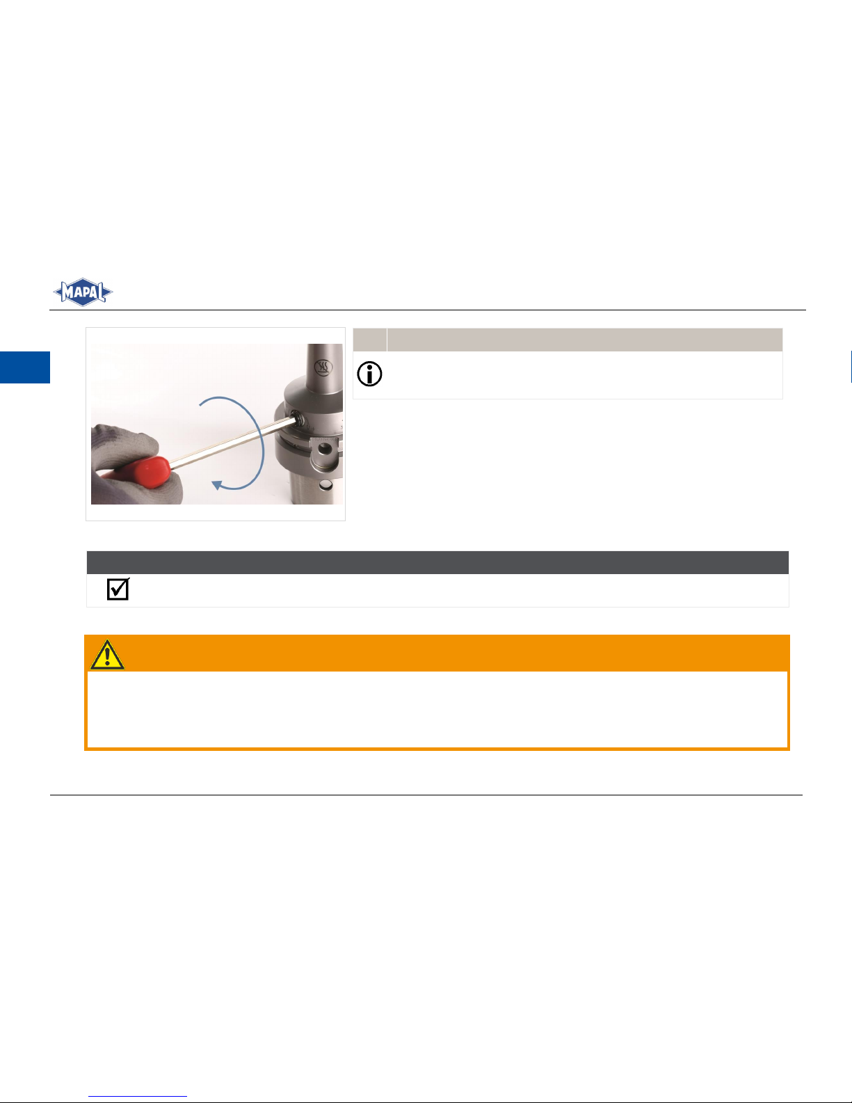
Drehen Sie die Spannschraube mit Hilfe eines Innensechskantschlüssels
4.
mit Quergriff bis zum Anschlag (siehe Abb. 11: Werkzeug spannen).
Stellen Sie einen Drehmomentschlüssel auf das Anzugsdrehmoment
5.
von 7 Nm ein.
Ziehen Sie die Spannschraube mit Hilfe des Drehmomentschlüssels auf
6.
Anschlag fest.
ERGEBNIS
Das Werkzeug ist nun vollständig im Hydrodehnspannfutter gespannt und kann eingesetzt werden.
5.2 Entspannen eines Werkzeugs
WARNUNG
Entspannen bei zu hoher Spannfuttertemperatur!
Durch das Entspannen bei zu hoher Spannfuttertemperatur können sich Teile des Hydrodehnspannfutters geschossartig
lösen und heißes Öl austreten. Dies kann zu schweren Verletzungen führen und Maschinen und Zubehör beschädigen.
Die Spannschraube des Hydrodehnspannfutters ausschließlich bei Raumtemperatur betätigen.
Werkzeug spannen
Abb. 11:
Page 25
Montage- und Betriebsanleitung
Installation and Operating Instructions
25
DE
INFORMATION
Die Spannschraube ist nicht gegen Herausfallen gesichert.
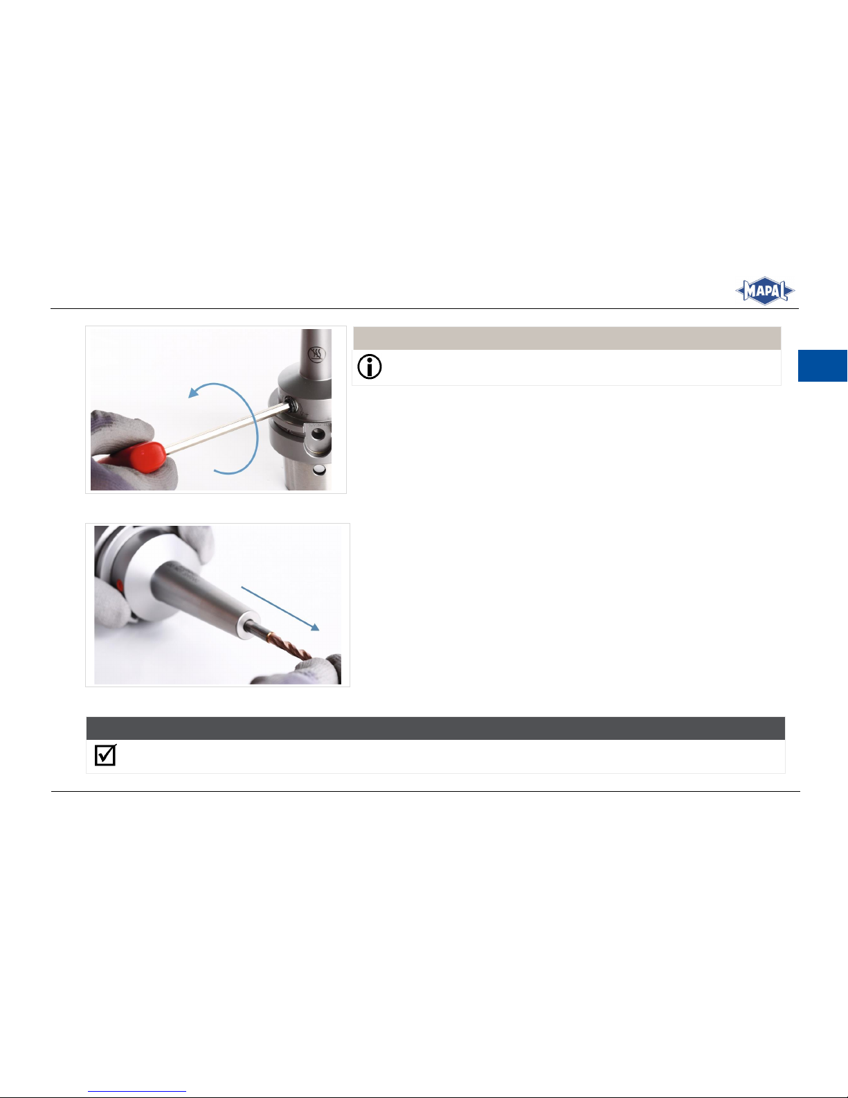
Lösen Sie die Spannschraube mit 3 bis 7 Umdrehungen mit Hilfe des pas-
1.
senden Innensechskantschlüssels mit Quergriff.
Spannschraube lösen
Abb. 12:
Entnehmen Sie das Werkzeug aus der Aufnahmebohrung des Hydrodehn-
2.
spannfutters.
Werkzeug entnehmen
Abb. 13:
ERGEBNIS
Das Werkzeug ist nun entspannt und gelöst.
Page 26
26
Montage- und Betriebsanleitung
Installation and Operating Instructions
DE
5.3 Maschinenseitige Anpassung der Kühlmittelzuführung nach Form AD/AF
WARNUNG
Verbrennungsgefahr durch heißen Gewindestiftbereich!
Beim Erwärmen und Herausdrehen der Gewindestifte können schwere Verbrennungen und Verletzungen ent-
stehen.
Beim Erwärmen und Herausdrehen der Gewindestifte immer ISO-Schutzhandschuhe tragen.
Nach dem Erwärmen warten, bis der Gewindestiftbereich abgekühlt ist.
Das System der Kühlmittelzuführung bei Werkzeughaltern nach DIN ISO 7388 erlaubt es, die gängigen Formen der Kühlmittelversorgung in einem maschinenseitigen Grundkörper nach Form AD/AF zu kombinieren.
Das System ermöglicht die Kombination folgender Ausführungen:
Form AD: zentrale Kühlmittelzuführung über durchgehende Bohrung (Grundeinstellung)
Form AF: zentrale Kühlmittelzuführung über Bund
Um die Werkzeughalter auf die Art der Kühlmittelversorgung der Maschine anzupassen genügt es, die Position zweier Gewindestifte zu ändern. Die Gewindestifte (mit Schraubensicherung gesichert) dichten jeweils die Bohrung zur alternativen
Kühlmittelzufuhr ab. Für die Umstellung steht Ihnen auch der MAPAL Kundenservice zur Verfügung.
Page 27
Montage- und Betriebsanleitung
Installation and Operating Instructions
27
DE
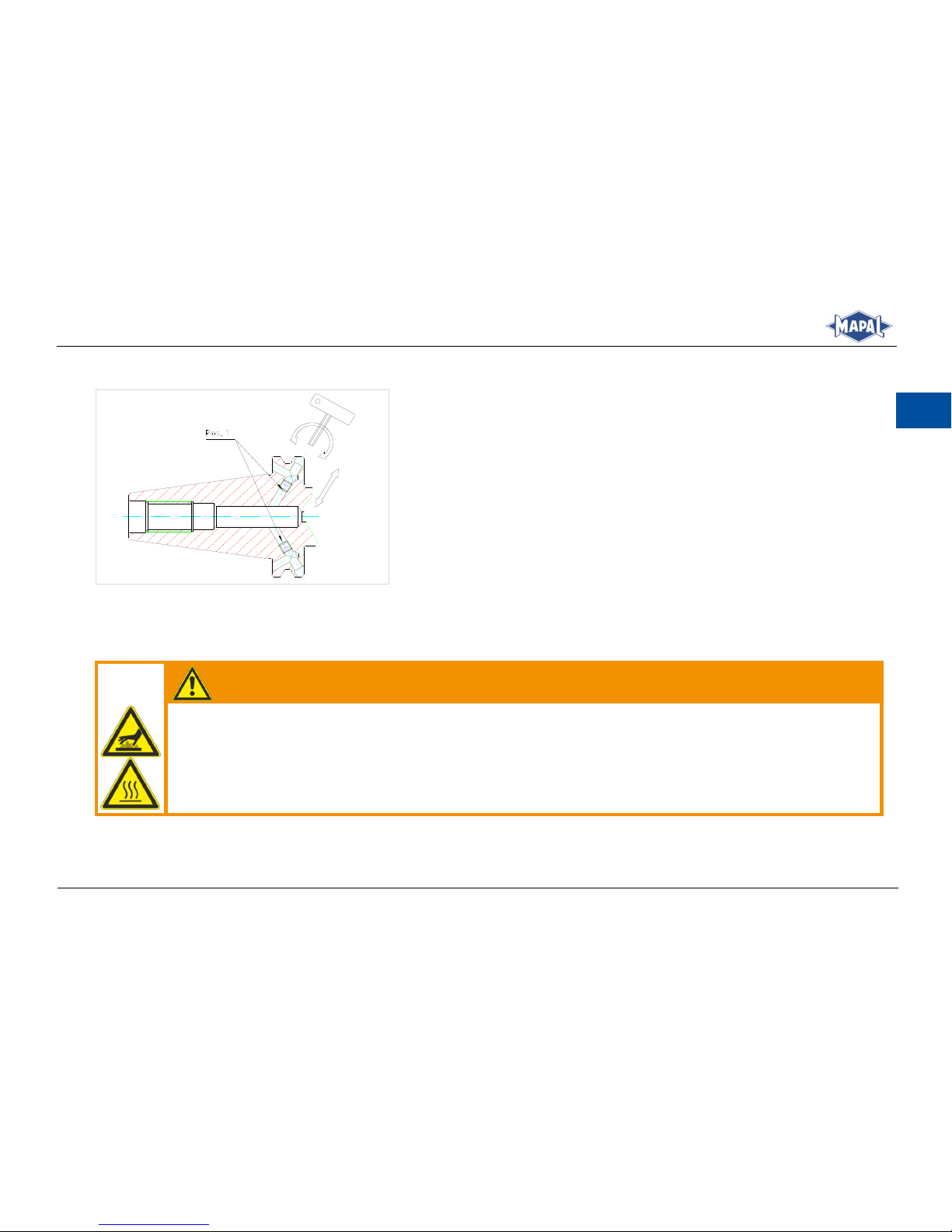
5.3.1 Grundeinstellung Form AD bzw. JD nach DIN ISO 7388
Falls keine andere Bestellung vorliegt, werden die Werkzeughalter
in Form AD ausgeliefert.
Grundeinstellung der Kühlmittelzuführung
Abb. 14:
5.3.2 Nach Form AF bzw. JF umstellen
Umstellung von der Grundeinstellung nach Kühlmittelzuführung Form AF.
WARNUNG
Verbrennungsgefahr durch heißen Gewindestiftbereich!
Beim Erwärmen und Herausdrehen der Gewindestifte können schwere Verbrennungen und Verletzungen ent-
stehen.
Beim Erwärmen und Herausdrehen der Gewindestifte immer ISO-Schutzhandschuhe tragen.
Nach dem Erwärmen warten, bis der Gewindestiftbereich abgekühlt ist.
Page 28
28
Montage- und Betriebsanleitung
Installation and Operating Instructions
DE
WARNUNG
Explosionsgefahr beim Erwärmen der Hydrodehnelemente!
Beim Erwärmen des Gewindestiftbereichs kann sich der Dehnspannbereich sowie die Bereiche der Druckeinlei-
tung erhitzen und das Hydrodehnspannfutter verformen oder explosionsartig platzen. Dabei können heißes Öl
oder Öldämpfe austreten und Metallsplitter geschossartig umherfliegen und schwere Verletzungen des Bedieners verursachen.
Ausschließlich den Gewindestiftbereich erwärmen.
Die Erwärmung nur im entspannten Zustand der Hydraulik durchführen.
Die Umstellung beim MAPAL Kundenservice veranlassen.
Stellen Sie die Kühlung des Hydraulikbereichs sicher.
1.
Erwärmen Sie die Gewindestifte bzw. den Gewindestiftbereich, bis sich die
2.
Gewindestifte herausdrehen lassen.
WARNUNG
Verbrennungsgefahr durch heißen Gewindestiftbereich!
ISO-Handschuhe tragen und warten, bis der Gewindestiftbereich ab-
gekühlt ist.
Drehen Sie die Gewindestifte mit einem Innensechskantschlüssel SW 2,5
3.
heraus.
Entfernen Sie die Klebstoffreste an den Gewindestiften und Gewindeboh-
4.
rungen.
Page 29
Montage- und Betriebsanleitung
Installation and Operating Instructions
29
DE
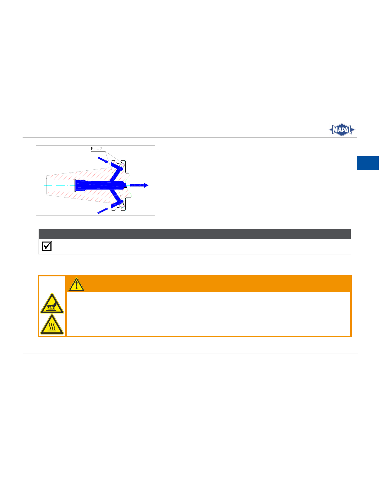
Schrauben Sie in den abgekühlten Werkzeughalter an „Pos. 2“ die Ge-
5.
windestifte mit Schraubensicherung (Klebstoff) mittelfest ein (siehe Abb.
15: Kühlmittelzuführung Form AF/JF).
Entfernen Sie eventuelle Klebstoffreste.
6.
Kontrollieren Sie nach der Aushärtezeit des Klebers die Gewindestifte auf
7.
festen Sitz und wuchten Sie den Werkzeughalter gegebenenfalls nach.
Verwenden Sie für die maschinenseitige Abdichtung des Werkzeughalters
8.
einen Anzugbolzen mit Kühlmittelbohrung.
Kühlmittelzuführung Form AF/JF
Abb. 15:
ERGEBNIS
Die Kühlmittelzuführung ist nach Form AF/JF umgestellt.
5.3.3 Nach Form AD bzw. JD umstellen
Umstellung der Kühlmittelzuführung von der Form AF nach Form AD.
WARNUNG
Verbrennungsgefahr durch heißen Gewindestiftbereich!
Beim Erwärmen und Herausdrehen der Gewindestifte können schwere Verbrennungen und Verletzungen ent-
stehen.
Beim Erwärmen und Herausdrehen der Gewindestifte immer ISO-Schutzhandschuhe tragen.
Nach dem Erwärmen warten, bis der Gewindestiftbereich abgekühlt ist.
Page 30
30
Montage- und Betriebsanleitung
Installation and Operating Instructions
DE
Erwärmen Sie die Gewindestifte bzw. den Gewindestiftbereich, bis sich
1.
die Gewindestifte herausdrehen lassen.
WARNUNG
Verbrennungsgefahr durch heißen Gewindestiftbereich!
ISO-Handschuhe tragen und warten, bis der Gewindestiftbereich ab-
gekühlt ist.
Drehen Sie die Gewindestifte mit einem Innensechskantschlüssel SW 2,5
2.
heraus.
Entfernen Sie die Klebstoffreste an den Gewindestiften und Gewindeboh-
3.
rungen.
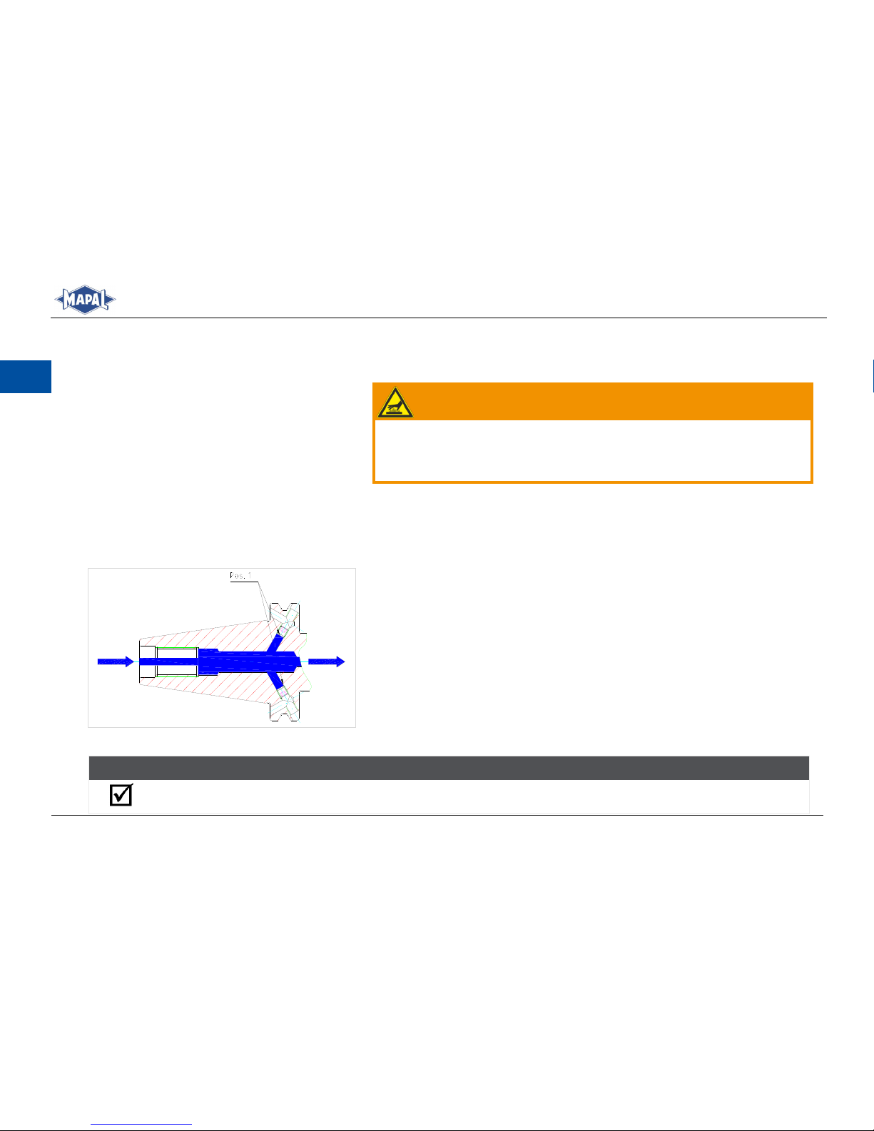
Schrauben Sie in den abgekühlten Werkzeughalter an „Pos. 1“ die Gewin-
4.
destifte mit Schraubensicherung (Klebstoff) mittelfest ein (siehe Abb. 16:
Kühlmittelzuführung Form AD/JD).
Entfernen Sie eventuelle Klebstoffreste.
5.
Kontrollieren Sie nach Aushärtezeit des Klebers die Gewindestifte auf fes-
6.
ten Sitz und wuchten Sie den Werkzeughalter gegebenenfalls nach.
Verwenden Sie für die maschinenseitige Abdichtung des Werkzeughalters
7.
einen Anzugbolzen mit Kühlmittelbohrung.
Kühlmittelzuführung Form AD/JD
Abb. 16:
ERGEBNIS
Die Kühlmittelzuführung ist nach Form AD/JD umgestellt.
Page 31

Montage- und Betriebsanleitung
Installation and Operating Instructions
31
DE
Pflege und Wartung
6
Schützen Sie das Hydrodehnspannfutter bei der Lagerung vor Korrosion.
Achten Sie darauf, dass das Hydrodehnspannfutter im entspannten Zustand gelagert wird.
Entsprechend den Nutzungs- und Umgebungsbedingungen, sowie bei häufigem Spannen, ist die Spannschraube in re-
gelmäßigen Abständen zu reinigen und neu zu schmieren.
Bei häufigem Spannen ist die Anschlagschraube zur axialen Werkzeuglängeneinstellung in regelmäßigen Abständen
zu reinigen und zu schmieren.
Reparaturen dürfen ausschließlich bei MAPAL durchgeführt werden.
Hinweise für das Reinigen in einer Waschanlage:
- Das Hydrodehnspannfutter ausschließlich im entspannten Zustand reinigen.
- Die Spannschraube darf nur bei Raumtemperatur gespannt oder entspannt werden.
- Die Waschtemperatur darf höchstens 80 °C betragen.
- Nach der Reinigung ist die Spannschraube neu einzufetten.
Entsorgung
7
Nachdem das Gebrauchsende des Hydrodehnspannfutters erreicht ist, muss das Hydrodehnspannfutter einer umweltgerechten Entsorgung zugeführt werden. Das Hydrodehnspannfutter kann zur fachgerechten Entsorgung auch an MAPAL gesendet
werden.
Page 32

Page 33

Table of contents
1 Purpose of the installation and operating instructions ....................................................................................................... 34
2 Contact ............................................................................................................................................................................................. 34
3 Safety ................................................................................................................................................................................................ 35
3.1 Target group .................................................................................................................................................................................................................................... 35
3.2 Correct use ...................................................................................................................................................................................................................................... 35
3.3 Incorrect use ................................................................................................................................................................................................................................... 35
3.4 Warranty .......................................................................................................................................................................................................................................... 36
3.5 General warnings and safety instructions .............................................................................................................................................................................. 36
3.6 Warnings and symbols on the hydraulic chuck ..................................................................................................................................................................... 41
4 General information ...................................................................................................................................................................... 43
4.1 Illustration of an HTC with slender contour ........................................................................................................................................................................... 43
4.2 Marking of the actuating elements .......................................................................................................................................................................................... 44
4.3 Tools and materials required ...................................................................................................................................................................................................... 45
4.4 Technical data ................................................................................................................................................................................................................................ 46
4.5 Checking the clamping force ...................................................................................................................................................................................................... 49
5 Operation of the HTC with slender contour ............................................................................................................................ 50
5.1 Clamping a tool .............................................................................................................................................................................................................................. 50
5.2 Unclamping a tool ......................................................................................................................................................................................................................... 54
5.3 Machine-side adaptation of the coolant supply to Form AD/AF ...................................................................................................................................... 56
6 Care and maintenance .................................................................................................................................................................. 61
7 Disposal ............................................................................................................................................................................................. 61
Page 34

34
Montage- und Betriebsanleitung
Installation and Operating Instructions
EN
1 Purpose of the installation and operating instructions
The present Installation and Operating Instructions describe the proper operation of the HTC HighTorque Chuck with slender
contour and axial tool length adjustment (hereinafter referred to as “hydraulic chuck”). You will find detailed information
on how to clamp and unclamp a tool using the hydraulic chuck. In addition, the most important safety instructions on handling the hydraulic chuck are explained.
Section 5 contains a detailed description of the individual functions and actions necessary to successfully clamp and unclamp tools using the hydraulic chuck.
The installation and operating instructions form an integral part of the hydraulic chuck and must be kept in the immediate
vicinity of the hydraulic chuck where it is accessible to the personnel at all times. A basic precondition for safe working is
compliance with all the safety precautions and instructions for working given in these installation and operating instructions.
The local safety at work regulations and the general safety regulations for the field of application of the hydraulic chuck
must also be observed. Illustrations in these installation and operating instructions are provided for general understanding
and may differ from the actual design.
2 Contact
MAPAL Fabrik für Präzisionswerkzeuge Dr. Kress KG
Address
Obere Bahnstrasse 13
D-73431 Aalen, GERMANY
Telephone
+49 (0) 7361 585-0
Fax
+49 (0) 7361 585-1029
E-mail
Internet
www.mapal.com
Page 35

Montage- und Betriebsanleitung
Installation and Operating Instructions
35
EN
3 Safety
3.1 Target group
The hydraulic chuck may only be used by trained, authorised and dependable specialist personnel. The specialist personnel
must be able to recognise and avoid hazards and for this purpose must have read this document before using the hydraulic
chuck.
The specialist personnel is familiar with the health and safety regulations, safety stipulations and instructions from the machine manufacturer, which must be followed and observed during operation of the hydraulic chuck.
3.2 Correct use
The hydraulic chuck is intended exclusively for holding and clamping tools on cutting machines in industrial applica-
tions.
The hydraulic chuck has been specially designed for hydraulic clamping of rotating tools on machine tools for manual
and automatic tool changing.
The hydraulic chuck may only be used when observance of all the instructions given in this manual is assured.
Failure to observe these instruction can result in injuries or damage to machines and accessories for which MAPAL as-
sumes no liability.
3.3 Incorrect use
The hydraulic chuck may only be used in accordance with the technical data (see section 4.4).
The hydraulic chuck must not be heated on a shrink unit. It is not designed for the shrinking process and the associated
temperatures.
The hydraulic chuck must not be used for workpiece clamping.
The hydraulic chuck must not be modified and used for other applications.
Additional bores, threads and attachment parts may only be attached with the written approval of MAPAL.
Unauthorised modifications to the hydraulic chuck or incorrect use of the hydraulic chuck will void all and any warranty
claims against MAPAL.
Page 36

36
Montage- und Betriebsanleitung
Installation and Operating Instructions
EN
The manufacturer assumes no liability for accidents or damage resulting from use for other than the correct use.
3.4 Warranty
The warranty period is 24 months from the date of delivery ex works on condition of use for the correct use and observance
of the contents of the installation and operating instructions. The warranty is limited to 1-shift operation.
The hydraulic chuck including all its components and accessories must not be modified or used for non-authorised applications. Any modification to the hydraulic chuck or any unauthorised use will void all and any warranty claims against
MAPAL.
MAPAL expressly declines any liability for accidents or damage resulting from the use of damaged tools or damaged machine parts. Wear parts are not covered by the warranty.
3.5 General warnings and safety instructions
WARNING
Danger from use by untrained and unauthorised personnel!
The clamping of tools and their installation on a machine tool by untrained and unauthorised personnel can lead to haz-
ardous situations.
Only trained, authorised and dependable specialist personnel may clamp tools and install them on a machine tool.
The technical data on the machine connection must be observed by the specialist personnel.
The specialist personnel must be able to recognise and avoid hazards.
Page 37
Montage- und Betriebsanleitung
Installation and Operating Instructions
37
EN
WARNING
Failure to observe the technical data or operator error!
Failure to observe the technical data or operator error can result in serious injury to the operator and in machine dam-
age.
Observe the technical data given in section 4.4.
During clamping, screw in the clamping screw up to the stop, observing the specified minimum number of rotations.
Observe the prescribed values for the minimum clamping depth.
Observe the prescribed spindle speed limits for the machine-side connection.
Observe the maximum load limit for the machine-side connection in accordance with e.g. VDMA 34181.
If irregularities occur during operation, do not use the hydraulic chuck further for safety reasons and send it to
MAPAL for inspection or repair.
3.5.1 Dangers from heat development
WARNING
Shrinking or heating the hydraulic chuck can lead to injuries and damage to machines and accessories!
Shrinking or heating can cause the hydraulic chuck to become deformed or to burst explosively. Hot oil, oil
vapours and metal slivers can then fly around uncontrolled and cause serious injuries to the operator and
cause damage to machines and accessories.
Do not shrink the hydraulic chuck or heat it above the specified operating temperature.
Page 38
38
Montage- und Betriebsanleitung
Installation and Operating Instructions
EN
WARNING
Unclamping at excessive clamping chuck temperatures!
Unclamping at excessive clamping chuck temperatures can cause parts of the hydraulic chuck to fly off uncontrolled, al-
lowing hot oil to escape. This can lead to serious injuries and cause damage to machines and accessories.
Actuate the clamping screw of the hydraulic chuck only at room temperature.
NOTICE
Clamping without tool!
Clamping without tool can result in damage to the hydraulic chuck.
Do not clamp the hydraulic chuck without tool.
3.5.2 Mechanical hazards
WARNING
Clamping and unclamping with running machine!
Clamping and unclamping the hydraulic chuck with the machine running may result in serious injuries to the operator.
Actuate the hydraulic chuck only off the machine and with the machine at a standstill.
Page 39
Montage- und Betriebsanleitung
Installation and Operating Instructions
39
EN
WARNING
Use of long, projecting and heavy tools or extensions!
Use of long, projecting and heavy tools or with extensions can cause the tool or parts of the tool combination to fly off
like a projectile and cause serious injuries.
When using long, projecting and heavy tools or with extensions, reduce the spindle speed according to the individual
specifications and at the responsibility of the operator.
Observe also the individually specified maximum length and balancing value of the whole system when using exten-
sions.
With special designs, deviating drawing specifications may have to be taken into consideration.
Observe the maximum load limit for the machine-side connection.
CAUTION
Sharp cutting edges on the tool!
Sharp cutting edges may cause cutting injuries.
Wear protective gloves when changing tools.
NOTICE
Tool length adjustment with the tool clamped!
Performing an axial or radial tool length adjustment while the tool is completely clamped will result in damage to the
hydraulic chuck.
Do not change the tool length adjustment as long as the tool is clamped.
Page 40

40
Montage- und Betriebsanleitung
Installation and Operating Instructions
EN
NOTICE
Use of shanks with recesses!
Use of shanks with Form B and E (DIN 1835) or shanks with HB and HE (DIN 6535) can result in radial run-out errors and
inaccurate balancing value of the whole system.
Use only shanks with Form A or fine balance the whole system.
NOTICE
Damage to the paint-sealed bleeder screw!
In the event of damage to the paint-sealed bleeder screw, the hydraulic chuck is no longer functional and must be taken
out of operation immediately.
Do not damage or loosen the paint-sealed bleeder screw.
If the bleeder screw is damaged, the hydraulic chuck must not be used for safety reasons.
In the event of damage, send the hydraulic chuck to MAPAL for inspection and repair.
NOTICE
Wear due to use of a power screwdriver for tightening the clamping screw!
Use of a power screwdriver for tightening the clamping screw will result in increased wear of the clamping set.
Tighten the clamping screw only manually.
Page 41
Montage- und Betriebsanleitung
Installation and Operating Instructions
41
EN
3.6 Warnings and symbols on the hydraulic chuck
WARNING
Shrinking or heating the hydraulic chuck can lead to injuries and damage to machines and accessories!
Shrinking or heating can cause the hydraulic chuck to become deformed or to burst explosively. Hot oil, oil
vapours and metal slivers can then fly around uncontrolled and cause serious injuries to the operator and
cause damage to machines and accessories.
Do not shrink the hydraulic chuck or heat it above the specified operating temperature.
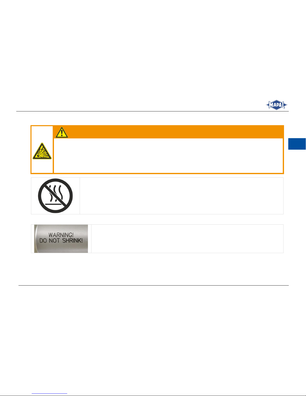
Prohibition symbol:
The prohibition symbol on the hydraulic chuck indicates expressly that the hydraulic chuck must
not be shrunk or heated.
Prohibition symbol on the hydraulic chuck
Fig. 1:
The hydraulic chuck bears this warning sign.
Warning sign on the hydraulic chuck
Fig. 2:
Page 42
42
Montage- und Betriebsanleitung
Installation and Operating Instructions
EN
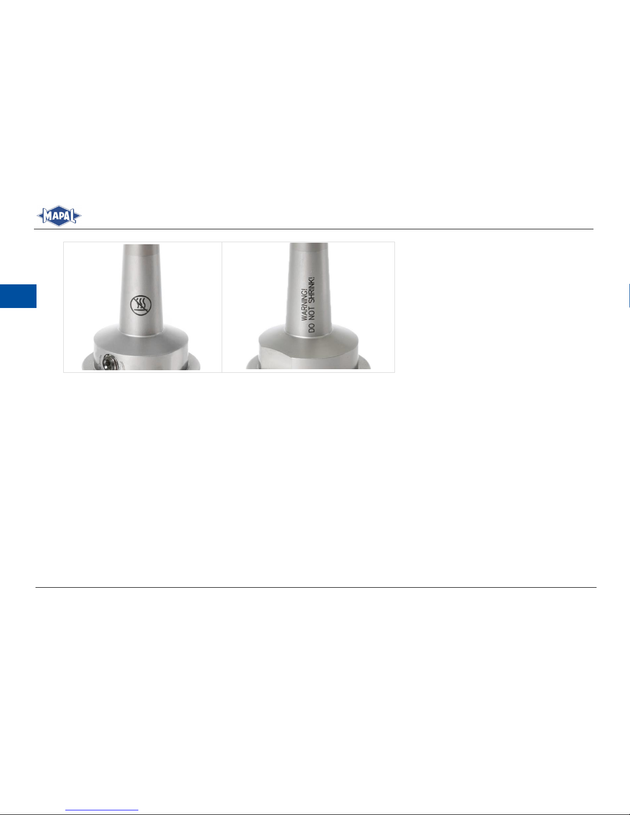
Position of prohibition symbol and warning sign on the hydraulic chuck
Fig. 3:
Page 43
Montage- und Betriebsanleitung
Installation and Operating Instructions
43
EN
4 General information
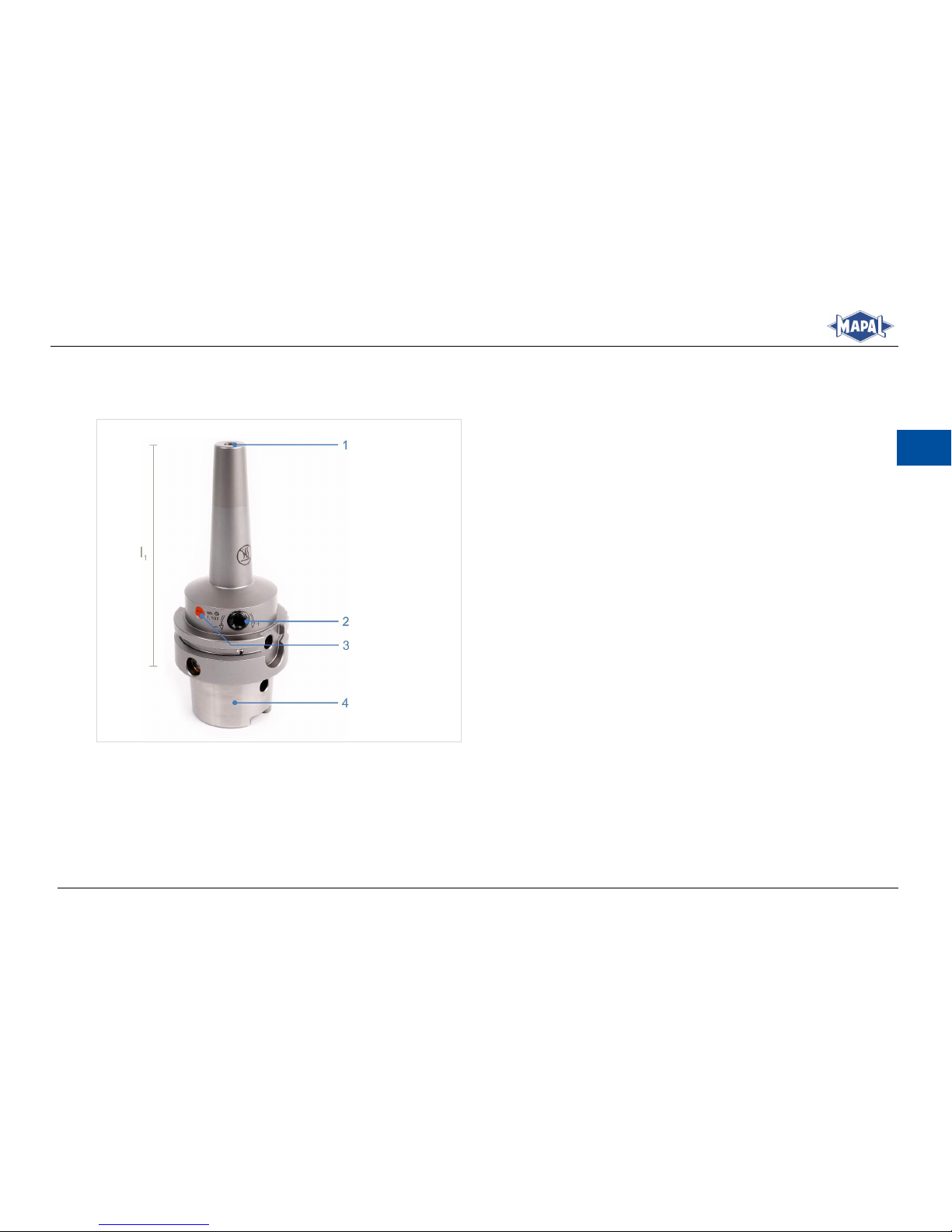
4.1 Illustration of an HTC with slender contour
Key
1 | Location bore
2 | Clamping screw
3 | Paint-sealed bleeder screw
4 | Taper of the hydraulic chuck
l1 | Projection length
Individual components of the HTC with slender contour
Fig. 4:
Page 44
44
Montage- und Betriebsanleitung
Installation and Operating Instructions
EN
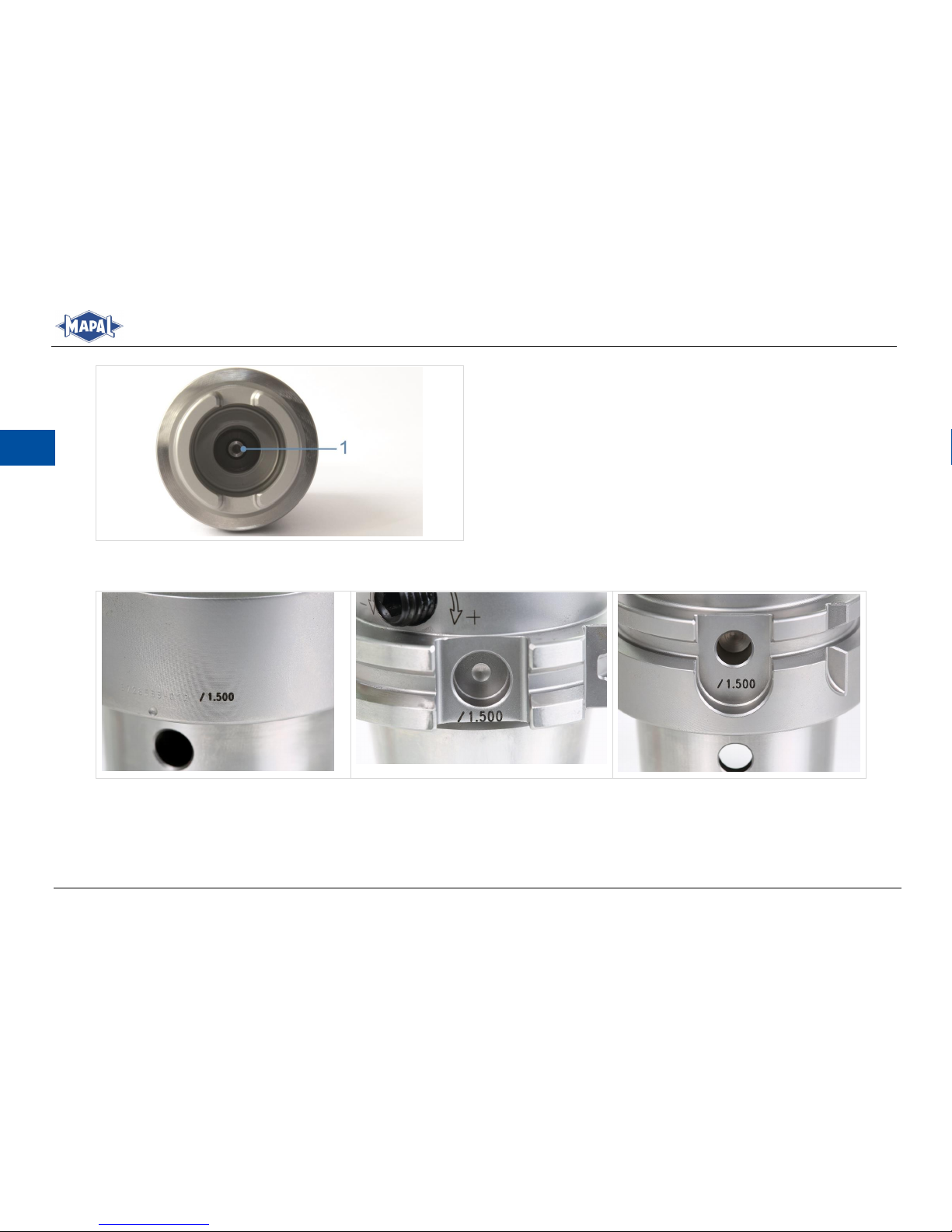
Key
1 | Stop screw for axial tool length adjustment
View of the HTC with slender contour from below
Fig. 5:
4.2 Marking of the actuating elements
Marking for checking of the clamping force: Three possible positions on the clamping chuck
Fig. 6:
Page 45
Montage- und Betriebsanleitung
Installation and Operating Instructions
45
EN
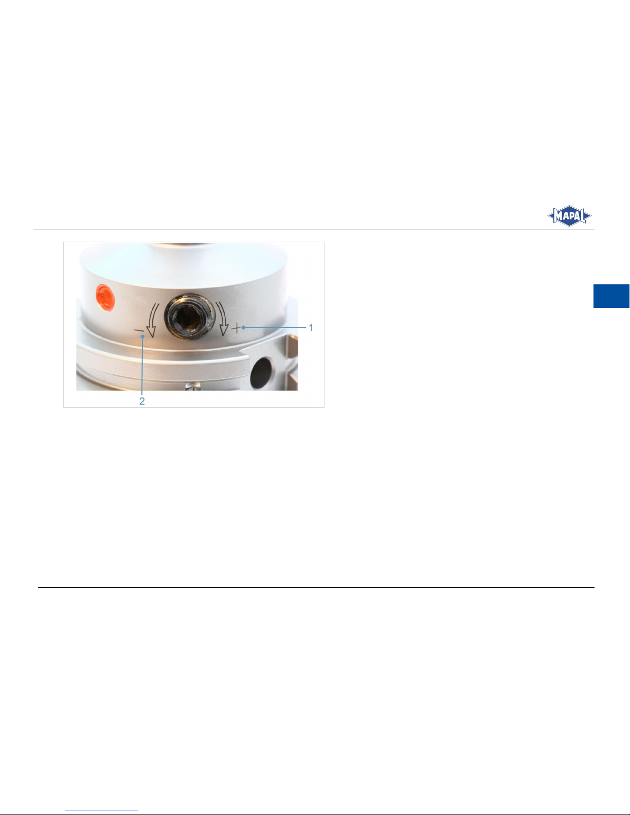
Key
1 | + Clamp tool (in clockwise direction)
2 | - Unclamp tool (in anticlockwise direction)
Indication of the direction of rotation for clamping and
Fig. 7:
unclamping the tool
4.3 Tools and materials required
Hex-wrench for the stop screw for axial tool length adjustment.
Hex-wrench for the clamping screw.
Page 46

46
Montage- und Betriebsanleitung
Installation and Operating Instructions
EN
4.4 Technical data
WARNING
Failure to observe the technical data!
Failure to observe the technical data can result in serious injury to the operator and in machine damage.
Observe the technical data given in section 4.4.
During clamping, screw in the clamping screw up to the stop, observing the specified minimum number of rotations.
Observe the prescribed values for the minimum clamping depth.
Observe the prescribed spindle speed limits for the machine-side connection.
Observe the maximum load limit for the machine-side connection in accordance with e.g. VDMA 34181.
If irregularities occur during operation, do not use the hydraulic chuck further for safety reasons and send it to
MAPAL for inspection or repair.
General technical data:
Material 1600 N/mm
2
.
Hardness 52+2 HRc
Tool holders balanced as standard.
Operating temperature: 20 to 120 °C.
Coolant pressure maximum 80 bar.
Maximum adjustment path 10 mm.
Cylindrical shanks, with and without reducing sleeves, with shank tolerance h6 according to DIN 1835 forms A, B,
E and according to DIN 6535 forms HA, HB and HE can be clamped.
Specification for checking of the clamping force (see sections 4.2 and 4.5).
Page 47

Montage- und Betriebsanleitung
Installation and Operating Instructions
47
EN
Indicative values for the spindle speed limits for hydraulic chucks with HSK connection
Nominal size
HSK
Max. permissible spindle
speed limit [rpm]
32
37.500
40
37.500
50
30.000
63
24.000
80
20.000
100
16.000
Indicative values for spindle speed limits
Tab. 1:
Page 48

48
Montage- und Betriebsanleitung
Installation and Operating Instructions
EN
Technical data [mm]
Clamping diameter [mm]
Minimum clamping
depth [mm]
Permissible transferrable
torque for shank h6 minimum
size [Nm]
Max. spindle speed [rpm]
l1 ≤ 125 mm
l1 > 125 mm
3
12
3
40.000
20.000
4
16 6 5
20
10
6
27
20
7
27
20 8 27
35 9 31
50
10
31
65
11
31
85
12
36
110
13
36
110
20.000
10.000
14
36
120
16
39
160
18
39
200
20
41
260
Technical data [mm]
Tab. 2:
Page 49

Montage- und Betriebsanleitung
Installation and Operating Instructions
49
EN
Technical data [inch]
Clamping diameter [inch]
Minimum clamping
depth [mm]
Permissible transferrable
torque for shank h6 minimum
size [Nm]
Max. spindle speed [rpm]
l1 ≤ 125 mm
l1 > 125 mm
1/8
12
3
40.000
20.000
3/16
16
8
1/4
27
20
5/16
27
35
3/8
31
65
7/16
31
85
1/2
36
110
5/8
39
150
20.000
10.000
3/4
41
260
Technical data [inch]
Tab. 3:
4.5 Checking the clamping force
The minimum number of rotations are indicated on the hydraulic chuck (see section 4.2) and provide a simple and reliable
check of the clamping force. This ensures that the minimum transferable torque is achieved at each clamping operation.
The minimum number of rotations are the number of rotations of the clamping screw that have to be achieved from the
gripping point of the shank up to the stop of the clamping screw. The gripping point is the position of the clamping screw
in which the tool shank can no longer be turned with two fingers or pulled out of the location bore.
Page 50
50
Montage- und Betriebsanleitung
Installation and Operating Instructions
EN
5 Operation of the HTC with slender contour
5.1 Clamping a tool
INFORMATION
Actuation of the stop screw of the hydraulic chuck is possible from both sides. The hydraulic chuck can be adjusted either axially or radially, depending on the design.
WARNING
Shrinking or heating the hydraulic chuck can lead to injuries and damage to machines and accessories!
Shrinking or heating can cause the hydraulic chuck to become deformed or to burst explosively. Hot oil, oil
vapours and metal slivers can then fly around uncontrolled and cause serious injuries to the operator and
cause damage to machines and accessories.
Do not shrink the hydraulic chuck or heat it above the specified operating temperature.
WARNING
Clamping and unclamping with running machine!
Clamping and unclamping the hydraulic chuck with the machine running may result in serious injuries to the operator.
Actuate the hydraulic chuck only off the machine and with the machine at a standstill.
Page 51
Montage- und Betriebsanleitung
Installation and Operating Instructions
51
EN
CAUTION
Sharp cutting edges on the tool!
Sharp cutting edges may cause cutting injuries.
Wear protective gloves when changing tools.
INFORMATION
Clamp only undamaged and burr-free tools.
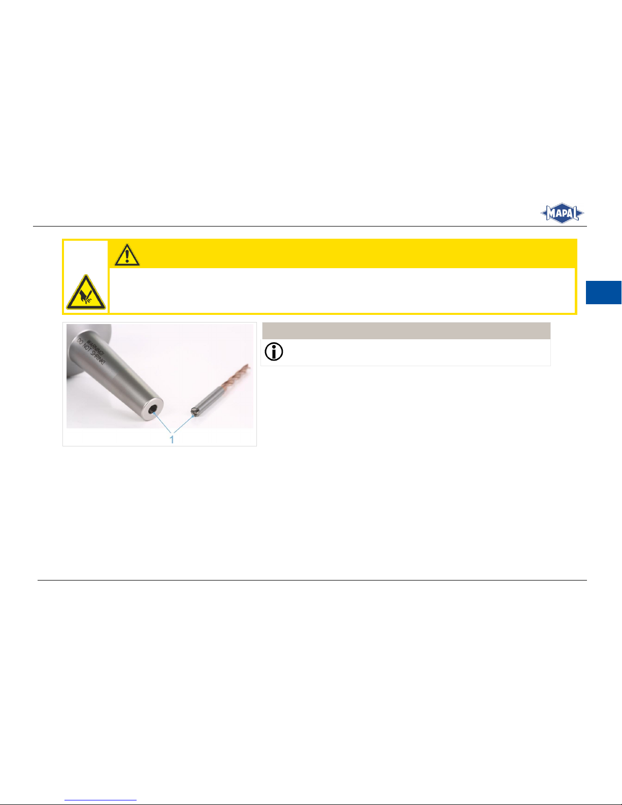
Clean the location bore and the tool shank (1).
1.
Cleaning hydraulic chuck and tool
Fig. 8:
Page 52
52
Montage- und Betriebsanleitung
Installation and Operating Instructions
EN
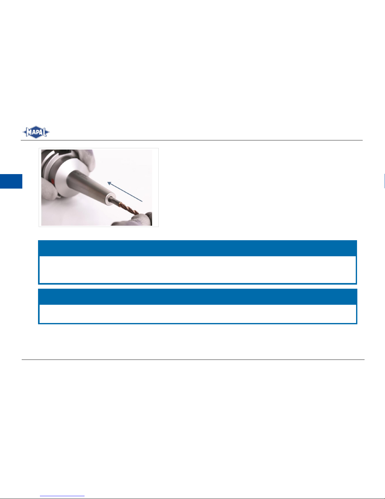
Push the tool, shank first, to the stop screw in the location bore in the
2.
hydraulic chuck.
Inserting tool
Fig. 9:
NOTICE
Damage from failure to observe the minimum clamping depth in the hydraulic chuck!
Observe the prescribed values for the minimum clamping depth (see Tab. 2: Technical data [mm]or Tab. 3: Technical
data [inch]).
NOTICE
Damage caused by tool length adjustment with clamped tool!
Do not change the tool length adjustment as long as the tool is clamped.
Page 53
Montage- und Betriebsanleitung
Installation and Operating Instructions
53
EN
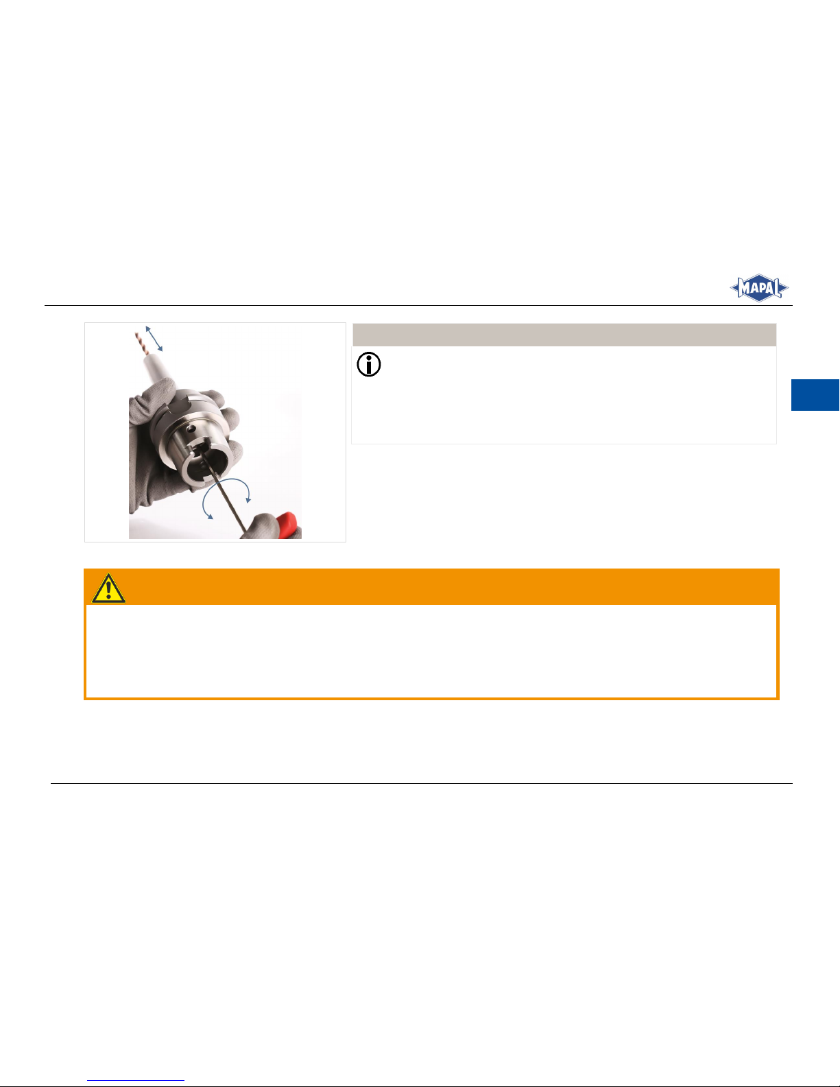
Adjust the hydraulic chuck to the tool length by turning the stop screw
3.
for the axial tool length adjustment using an appropriate hex-wrench
with T-handle.
INFORMATION
The stop screw for axial tool length adjustment is not secured to
prevent it from falling out. The specified adjusting range cannot be
exceeded.
Actuation of the stop screw for axial tool length adjustment is possible from both sides.
Adjusting the tool length
Fig. 10:
WARNING
Insufficient clamping up to the stop and failure to observe the minimum number of turns!
Insufficient clamping up to the stop and failure to observe the minimum number of rotations can cause the workpiece to
fly off like a projectile and cause serious injuries.
During clamping, screw in the clamping screw up to the stop, observing the specified minimum number of rotations
(see section 4.4).
Page 54
54
Montage- und Betriebsanleitung
Installation and Operating Instructions
EN
INFORMATION
The clamping screw is not captive!
Ensure that the clamping screw is clean.
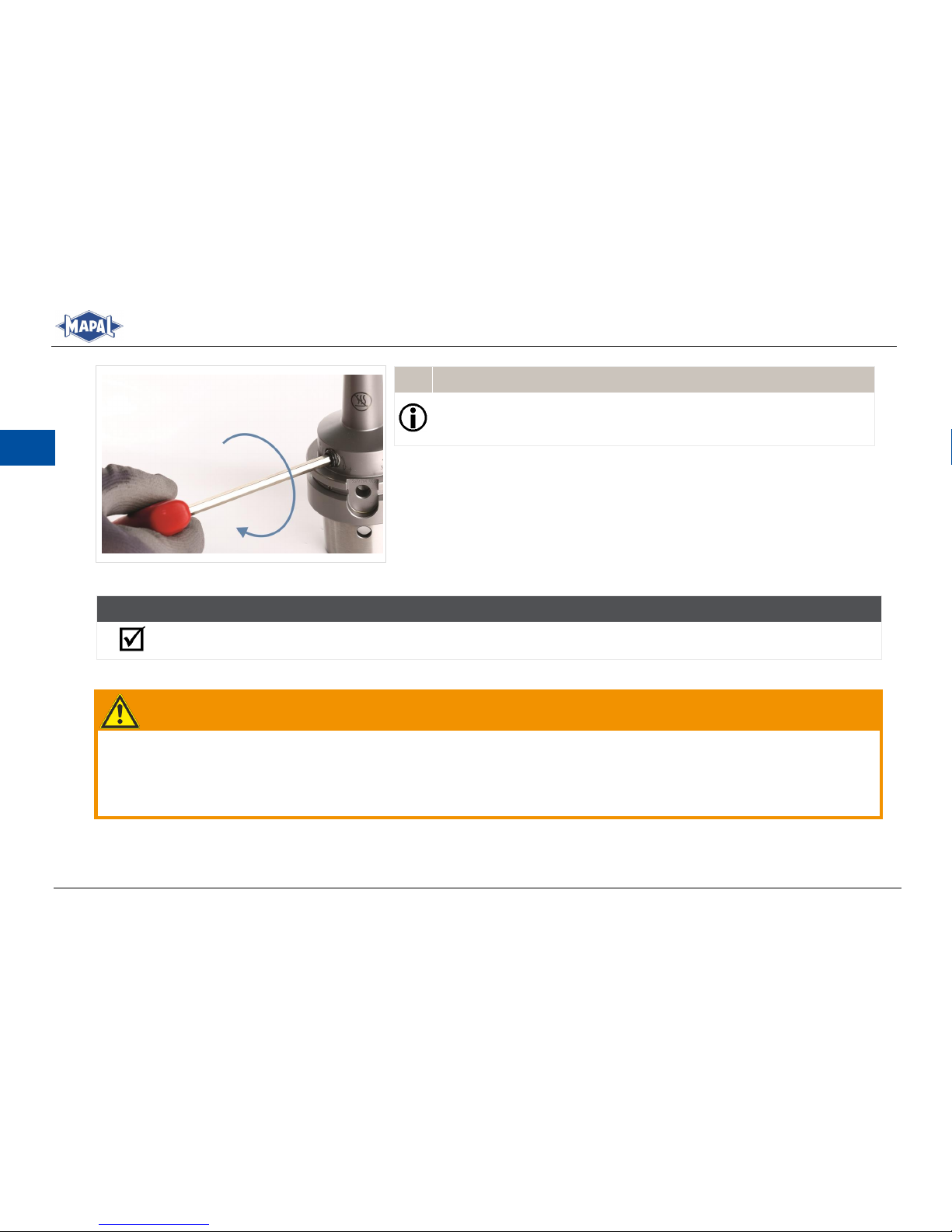
Turn the clamping screw up to the stop using an hex-wrench with T-
4.
handle (see Fig. 11: Clamp the tool).
Set a torque wrench to a tightening torque of 7 Nm.
5.
Tighten the clamping screw to the stop with the aid of the torque
6.
wrench.
RESULT
The tool is now fully clamped in the hydraulic chuck and can be used.
5.2 Unclamping a tool
WARNING
Unclamping at excessive clamping chuck temperatures!
Unclamping at excessive clamping chuck temperatures can cause parts of the hydraulic chuck to fly off uncontrolled, al-
lowing hot oil to escape. This can lead to serious injuries and cause damage to machines and accessories.
Actuate the clamping screw of the hydraulic chuck only at room temperature.
Clamp the tool
Fig. 11:
Page 55
Montage- und Betriebsanleitung
Installation and Operating Instructions
55
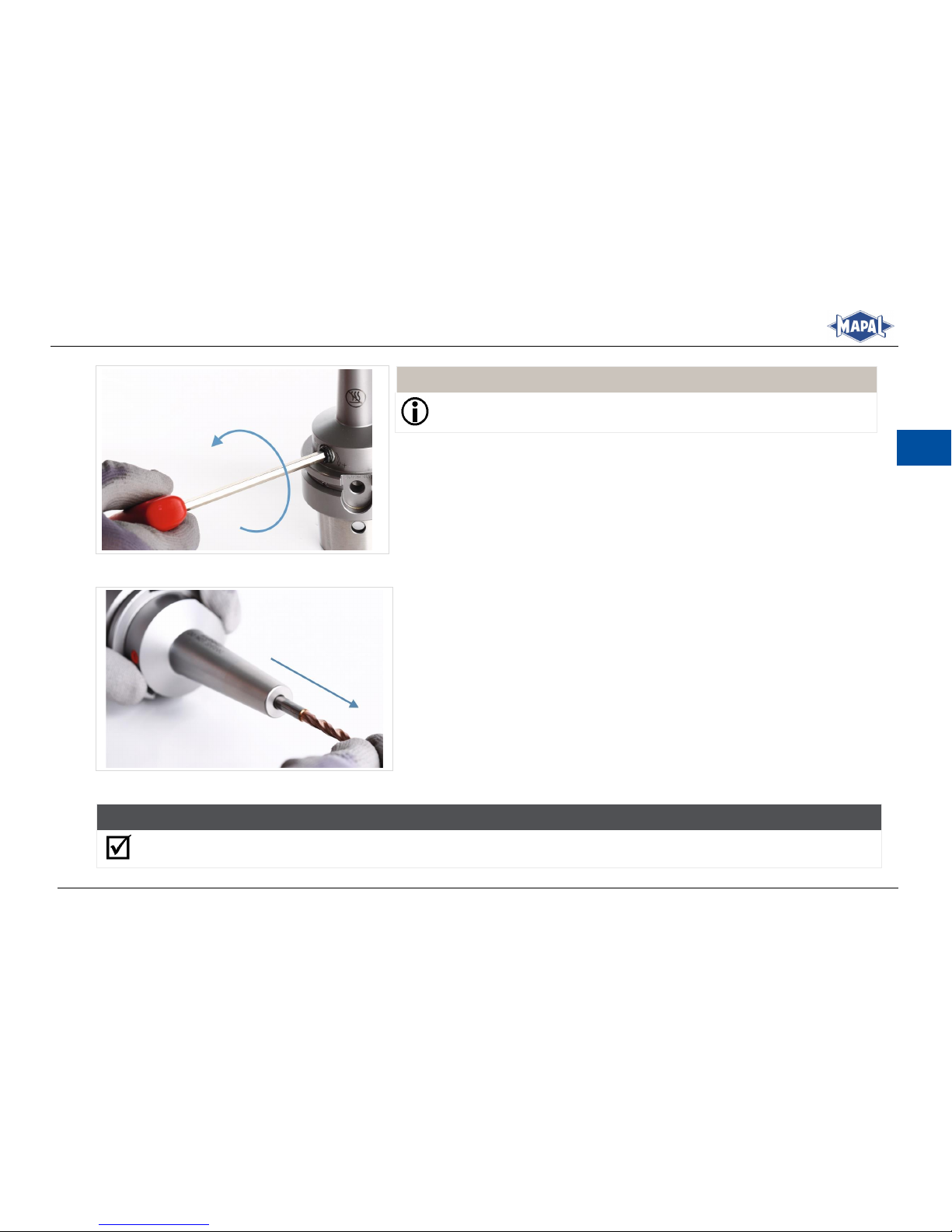
EN
INFORMATION
The clamping screw is not captive.
Loosen the clamping screw with 3 to 7 turns using an appropriate hex-
1.
wrench with T-handle.
Loosening clamping screw
Fig. 12:
Remove the tool from the location bore of the hydraulic chuck.
2.
Removing tool
Fig. 13:
RESULT
The tool has been unclamped and released.
Page 56
56
Montage- und Betriebsanleitung
Installation and Operating Instructions
EN
5.3 Machine-side adaptation of the coolant supply to Form AD/AF
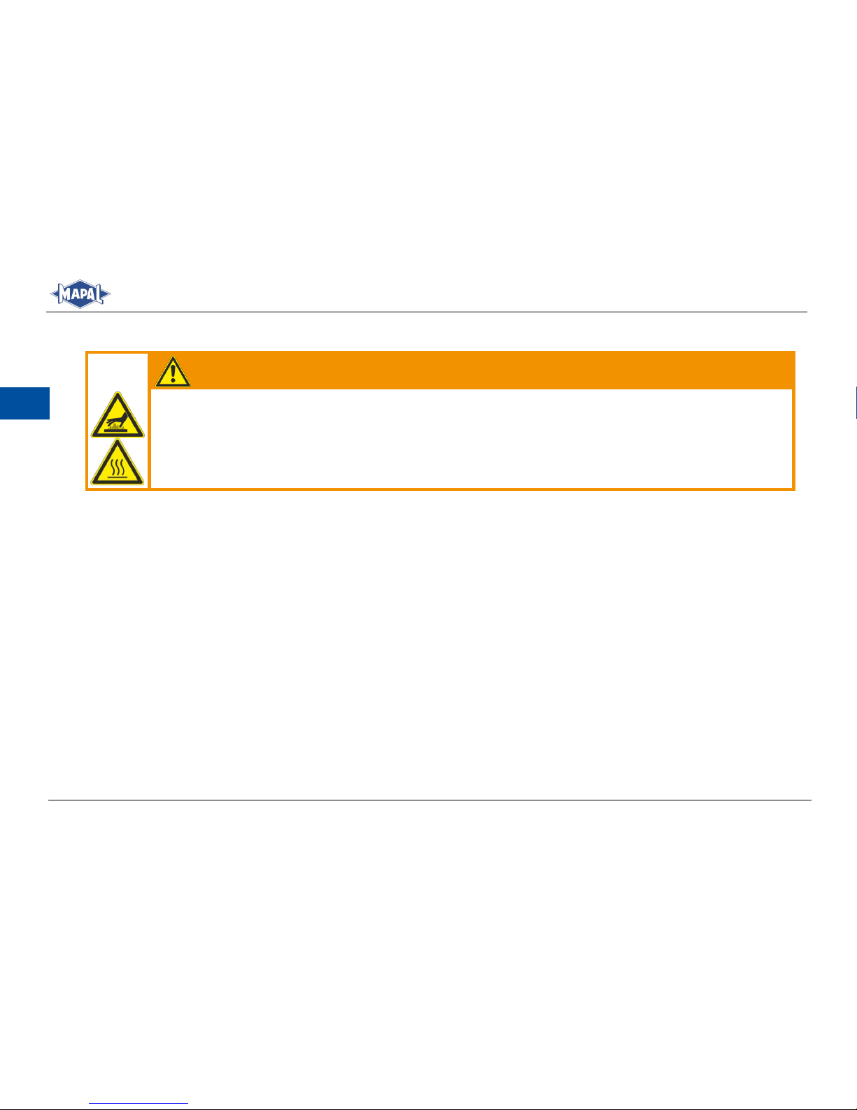
WARNING
Risk of burns from hot threaded pin area!
Serious burns and injuries can occur during heating and unscrewing the threaded pins.
Always wear ISO protective gloves when heating and unscrewing the threaded pins.
After heating, wait until the heated threaded pin area has cooled down.
The system for the coolant supply on tool holders to DIN ISO 7388 makes it possible to combine the common forms of coolant supply into one machine-side tool body of Form AD/AF.
The system makes it possible to combine the following designs:
Form AD: Central coolant supply via through bore (normal setting)
Form AF: Central coolant supply via collar
To adjust the tool holder to the type of coolant supply on the machine, it is sufficient to adjust the position of two threaded
pins. The threaded pins (secured with thread locking compound) seal off the bore for the alternative coolant supply. MAPAL
After-sales Service is also at your disposal for the changeover.
Page 57
Montage- und Betriebsanleitung
Installation and Operating Instructions
57
EN
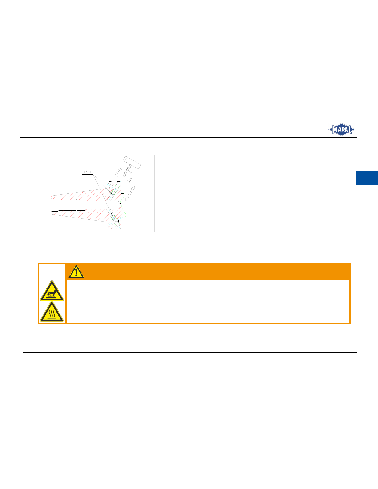
5.3.1 Normal setting Form AD or JD to DIN ISO 7388
Unless otherwise indicated in the purchase order, the tool holders are delivered in Form AD.
Normal setting of the coolant supply
Fig. 14:
5.3.2 Change over to Form AF or JF
Change over of the normal setting to coolant supply Form AF.
WARNING
Risk of burns from hot threaded pin area!
Serious burns and injuries can occur during heating and unscrewing the threaded pins.
Always wear ISO protective gloves when heating and unscrewing the threaded pins.
After heating, wait until the heated threaded pin area has cooled down.
Page 58
58
Montage- und Betriebsanleitung
Installation and Operating Instructions
EN
WARNING
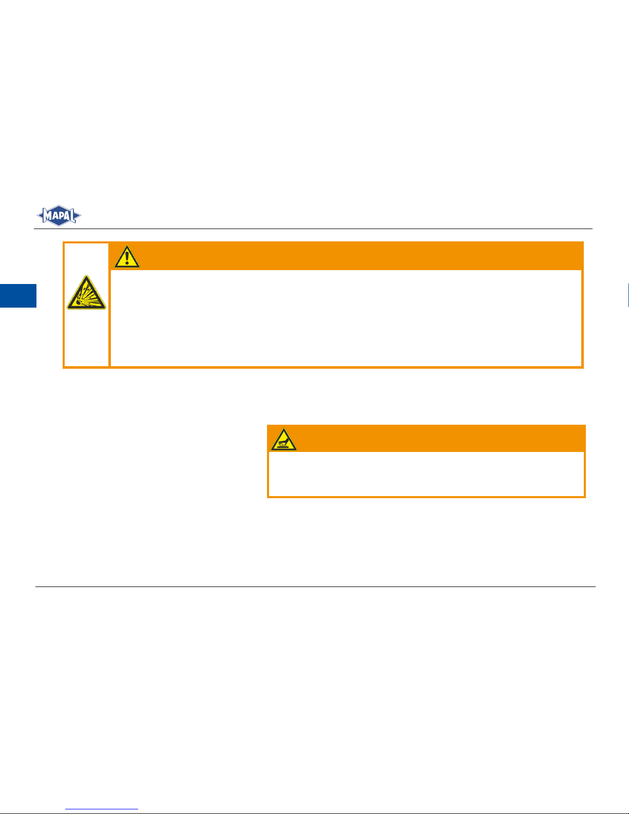
Risk of explosion during heating of the hydraulic elements!
During heating of the part of the threaded pin, the chucking section and the pressure application areas can
become hot and cause the hydraulic chuck to become deformed or to burst explosively. Hot oil or oil vapour
can escape and metal slivers can then fly around uncontrolled and cause serious injuries to the operator.
Heat only the area of the threaded pin.
Carry out heating only with the hydraulics in the unclamped position.
Have the modification carried out by MAPAL After-sales Service.
Ensure that the area of the hydraulics is cooled adequately.
1.
Heat the threaded pins or the threaded pin area until the threaded pins
2.
can be unscrewed.
WARNING
Risk of burns from hot threaded pin area!
After heating, wait until the heated threaded pin area has cooled
down.
Unscrew the threaded pins using an hex-wrench 2.5.
3.
Remove the adhesive residues from the threaded pins and threaded bores.
4.
Page 59
Montage- und Betriebsanleitung
Installation and Operating Instructions
59
EN
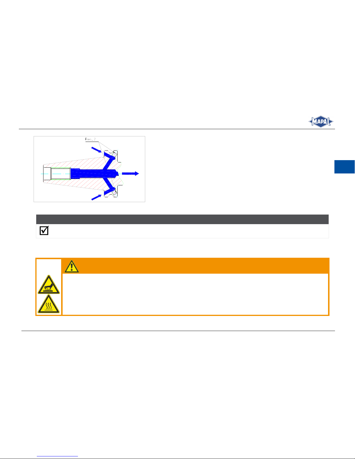
Screw the threaded pins with medium-strength thread locking com-
5.
pound (adhesive) into the cooled tool holder at “Pos. 2” (see Fig. 15:
Coolant Supply Form AF/JF).
Remove any adhesive residues.
6.
After the curing time of the adhesive, check the threaded pins for secure
7.
fitting and rebalance the tool holder, if necessary.
Use a pull stud with coolant bore for the machine-side sealing of the
8.
tool holder.
Coolant Supply Form AF/JF
Fig. 15:
RESULT
Coolant supply is changed over to Form AF/JF.
5.3.3 Change over to Form AD or JD
Change over of the coolant supply from Form AF to Form AD.
WARNING
Risk of burns from hot threaded pin area!
Serious burns and injuries can occur during heating and unscrewing the threaded pins.
Always wear ISO protective gloves when heating and unscrewing the threaded pins.
After heating, wait until the heated threaded pin area has cooled down.
Page 60
60
Montage- und Betriebsanleitung
Installation and Operating Instructions
EN
Heat the threaded pins or the threaded pin area until the threaded pins
1.
can be unscrewed.
WARNING
Risk of burns from hot threaded pin area!
After heating, wait until the heated threaded pin area has cooled
down.
Unscrew the threaded pins using an hex-wrench 2.5.
2.
Remove the adhesive residues from the threaded pins and threaded bores.
3.
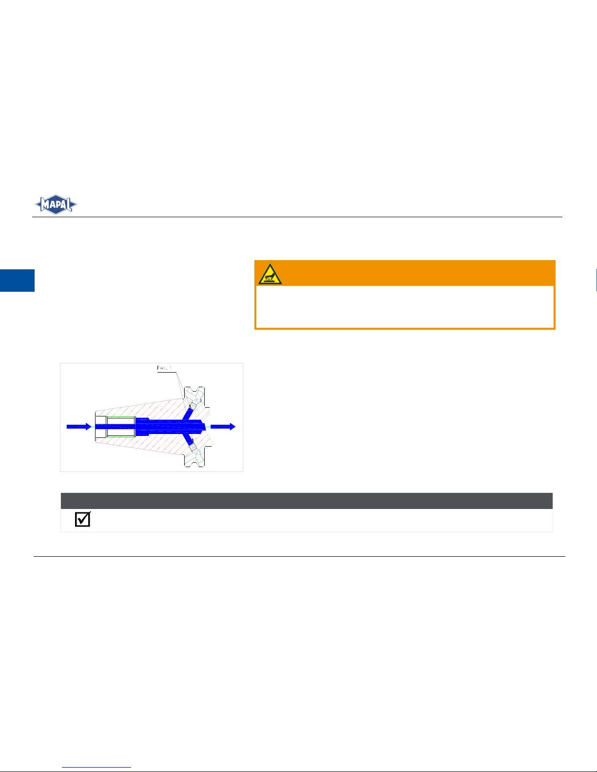
Screw the threaded pins with medium-strength thread locking compound
4.
(adhesive) into the cooled tool holder at “Pos. 1” (see Fig. 16: Coolant
Supply Form AD/JD).
Remove any adhesive residues.
5.
After the curing time of the adhesive, check the threaded pins for secure
6.
fitting and rebalance the tool holder, if necessary.
Use a pull stud with coolant bore for the machine-side sealing of the tool
7.
holder.
Coolant Supply Form AD/JD
Fig. 16:
RESULT
Coolant supply is changed over to Form AD/JD.
Page 61

Montage- und Betriebsanleitung
Installation and Operating Instructions
61
EN
6 Care and maintenance
Protect the hydraulic chuck against corrosion during storage.
Ensure that the hydraulic chuck is stored in the unclamped position.
The clamping screw is to be cleaned and re-lubricated at regular intervals, depending on the operating and ambient
conditions and in the event of frequent loosening and tightening.
If the stop screw for axial tool length adjustment is clamped frequently, it must be cleaned and lubricated at regular in-
tervals.
Repairs may only be performed at MAPAL.
Instructions for cleaning in a washing facility:
- Clean the hydraulic chuck only in the unclamped position.
- The clamping screw may only be clamped or relieved at room temperature.
- The washing temperature must not exceed 80 °C.
- After cleaning, regrease the clamping screw.
7 Disposal
Once the hydraulic chuck reaches the end of its service life, it must be disposed of with due care for the protection of the
environment. The hydraulic chuck can also be sent to MAPAL for proper disposal.
Page 62

Page 63

Page 64

KAL-HTC-D/E-02-005-0818-FA Printed in Germany. Right of technical modification reserved.
KAL-HTC-D/E-02-0818
Bestellnummer / Order number:
10156707
Montage- und Betriebsanleitung | HighTorque Chuck HTC mit schlanker Kontur
Installation and Operating Instructions | HighTorque Chuck HTC with slender contour
MAPAL Dr. Kress KG, Aalen
Gültig für: / Applies for:
2. Auflage August 2018 / 2nd issue August 2018
© MAPAL Präzisionswerkzeuge Dr. Kress KG
Kein Teil dieser Anleitung darf in irgendeiner Form (Druck, Fotokopie, Mikrofilm oder einem anderen Verfahren)
ohne schriftliche Zustimmung der Firma MAPAL Präzisionswerkzeuge Dr. Kress KG, Aalen, reproduziert oder
unter Verwendung elektronischer Systeme verarbeitet werden.
No part of this manual is allowed to be copied or processed using electronic systems, in any form
(print, photocopy, microfilm or any other method) without the written approval of
MAPAL Präzisionswerkzeuge Dr. Kress KG, Aalen, Germany.
Alle in diesem Handbuch genannten Bezeichnungen von Erzeugnissen sind Warenzeichen der jeweiligen Firmen.
All the product names stated in this manual are trademarks of the related organisations.
Technische Änderungen vorbehalten.
We reserve the right to make technical changes without notice.
 Loading...