

Manzano Laser Works Junkers Ju 88 Assembly Manual
Copyright 2007 Thomas A. Jacoby and WarbirdKits.com
Junkers Ju 88
Junkers Ju 88Junkers Ju 88
Junkers Ju 88
Manual Version 1.2 – 13 March 2008
Specifications
Wingspan: 49.75 inches
Area: 339 square inches
Length: 36.12 inches
Power: 2x BP21 Brushless
2x Speed-400
Assembly Manual for Junkers Ju 88
Copyright 2007 Thomas A. Jacoby and WarbirdKits.com 2
Materials
This kit contains the following materials:
This construction manual
Plan sheet
Decal sheet
Laser-cut wood pack
Vacuum-formed plastic canopy
Vacuum-formed plastic nose glazing
Vacuum-formed plastic spinners (2)
To complete this kit, you will need the following additional
materials:
1/4” x 3/8” x 48” Balsa for wing leading edge
3/32” x 3” x 36” Balsa for fuselage sheeting
1/16” x 4” x 24” Balsa sheet for wing skin, 6 each
1/16” x 1/4” Balsa planks for nacelles
3/8” x 36” Balsa triangle stock for fuselage, 2 each
1/4” square Hardwood motor mounts (for Speed-400)
3/16” x 12” Hardwood dowel for elevator joiner
Wing mounting bolt
Hinges (ailerons, elevator)
Miscellaneous servo mounting materials and pushrods
Covering materials and paint
Glue
NOTE: We recommend that you read this entire
manual before beginning construction.
Construction
Wings
Assemble the wing skins. The easy way to do this is
tape them together on the “good” side. Use low-tack painter’s
tape so that it releases easily later on. Then bend the joints
open, apply a thread of aliphatic resin in the groove, then close
the joints. Lay a sheet of wax paper on a flat surface, lay the
glued skin on it, cover with another sheet of wax paper, and
weight with heavy books. As you glue each skin, add it to the
stack, making sure you put a sheet of wax paper between
each skin. Let the glue dry overnight.
Using the same procedure as in step 1, assemble two
wing top skins, using the bottom skins as templates. Make the
top skin about 1/4” wider (chord-wise) than the bottom skin.
Block sand the good side of the wing skins. Make them
nice and smooth, as this will be the outer surface of the wing,
and it’s hard to sand later on.
Begin with the left wing. Cover your building board with
a sheet of wax paper. Remove the balsa from the aileron
hatch location, and pin the bottom left skin to the building
board. Keep your plan separate for reference.
Cut, fit and glue the 1/4" x 3/8” leading edge to the
wing skin.
Remove one set of ribs W1 thru W11 from the laser-cut
sheets. Leave the aileron ribs (the rear sections of ribs W7
Assembly Manual for Junkers Ju 88
Copyright 2007 Thomas A. Jacoby and WarbirdKits.com 3
thru W11) attached to the sheet for now. Also remove spars
W12 thru W14 from the sheets.
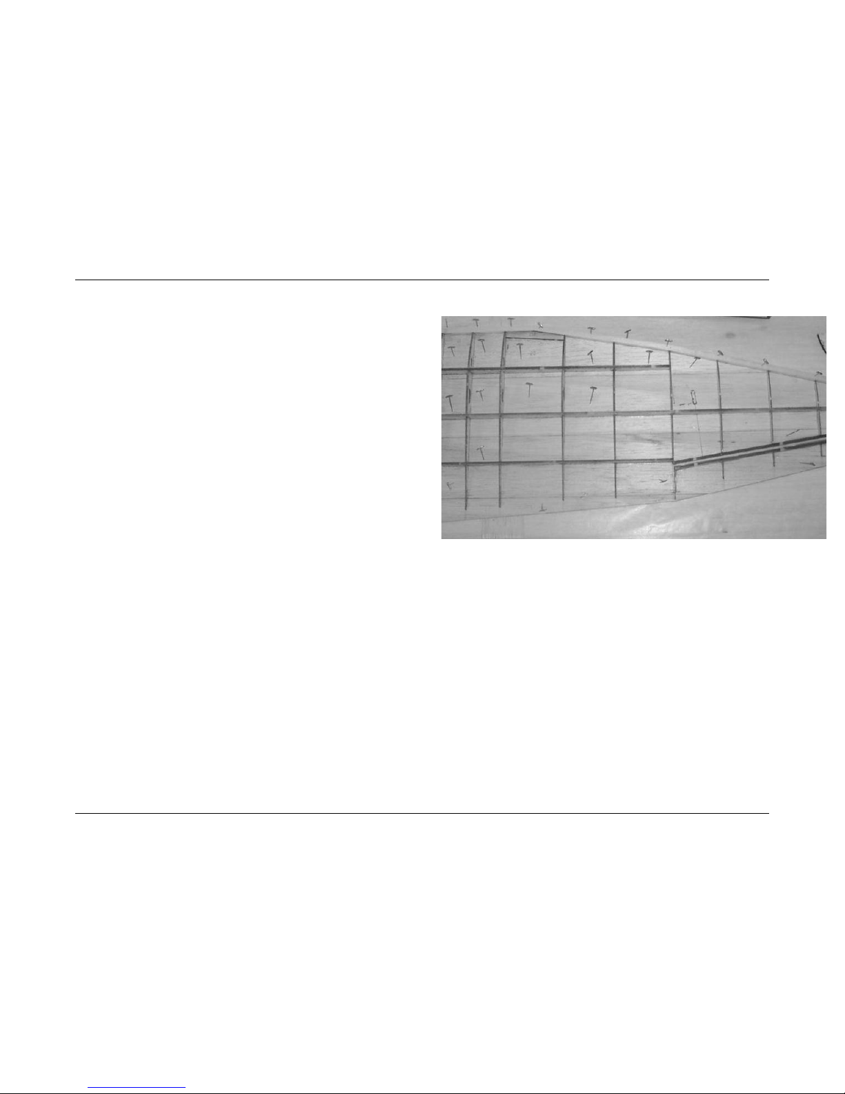
Trial-fit the wing ribs to the spars. Place the assembled
ribs and spars on the skin and align with the etched lines. Glue
the ribs to the bottom skin. Make sure that W1 fully engages
the notches in the spars so that the correct dihedral angle is
established. Then glue the three main spars to the skin and
ribs. Glue braces G1 and G2 in place where rib W7 meets the
leading edge.
Glue spar W15 in place. Now find the rear section of rib
W7 and glue it in place.
Find a scrap piece of 1/8” balsa sheet to use as a
spacer between W15 and W16. Carefully glue the aileron spar
W16 to the bottom skin, and remove the spacer.
Now glue the aileron ribs (from W7 thru W11) in place,
butting to the aileron spar.
Fit and glue leading edge brace W17 in place.
Glue the 1/16” plywood aileron hatch base in place.
Sand a taper into the trailing edge of the wing skin, so
that the skin is 1/32” thick at the trailing edge.
Repeat steps 3 thru 13 for the right wing.
NOTE: You may wish to apply the top skins to the wing before
joining the panels. If you do, remember to pull the motor and
servo wiring through!
Trial-fit the wing halves together. Pin down one side
and block up the other side so that there is 3-1/2” total dihedral
at the wingtip. Make sure that the two W1 ribs butt closely
together.
When satisfied with the fit, glue the wing halves
together with 15-minute epoxy between the W1 ribs. Let the
epoxy fully cure before moving the wing.
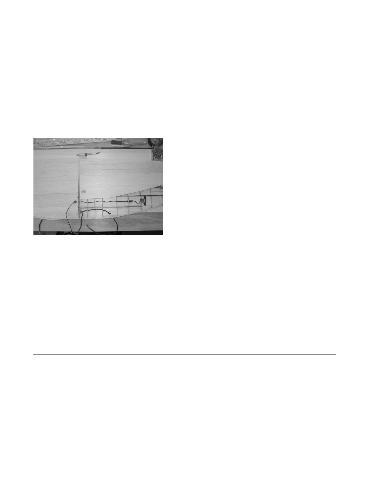
Install the servo leads and motor wiring in the two wing
halves.
Cut a hole in the top left wing skin for the motor wiring
to exit the wing. The hole should be about halfway between
ribs W1 and W2, ahead of the forward spar W13.
Cut a similar hole in the top right wing skin for the
aileron servo cables.
Assembly Manual for Junkers Ju 88
Copyright 2007 Thomas A. Jacoby and WarbirdKits.com 4
Fit and install the top wing skins. The easy way to do
this is a) apply aliphatic resin to the tops of the ribs and spars;
b) CA the skin to the leading edge; c) smooth the skin down
onto the ribs; and d) use thick CA to join the skins at the
trailing edge.
Reinforce the wing panel joint with a 1-1/2” fiberglass
bandage and 15-minute epoxy.
Assemble the wing tip blocks, and glue them to the
wing. Shape the wing tips.
Shape the leading edge per the plan.
Cut out the ailerons. Glue a 1/8 x 3/8 balsa strip to the
leading edge of each aileron, then shape the leading edge.
Cover the wing as desired.
Install the ailerons using your choice of hinges.
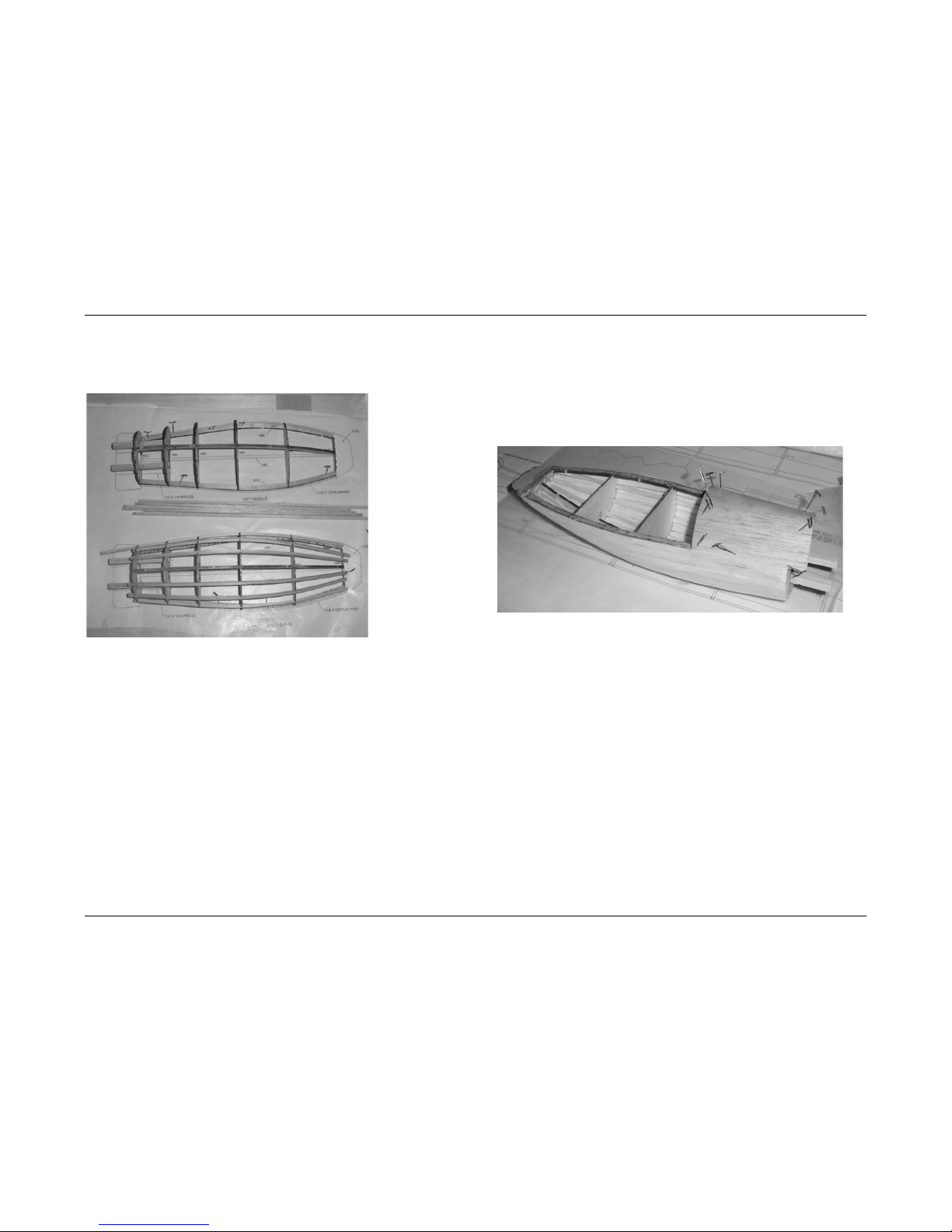
Nacelles
Tape the nacelle plans to your building board and
cover with wax paper. NOTE that the nacelle plans show the
nacelles from the bottom looking up! Also NOTE that the
nacelle parts are lettered with an “R” or an “L” to designate
their use on either the right or left nacelle.
Decide now whether you will use a Speed-400 motor or
an outrunner motor to power your Ju 88 model. If you decide
to use a Speed-400 (or brushless inrunner) motor, you will use
the 1/16” balsa firewalls N1 and two 1/4” square hardwood
motor mounts.
If using an outrunner brushless motor, laminate the 1/16” ply
firewalls N1 to the front of the balsa firewalls using a
carpenter’s wood glue (NOT CA).
If you are using a Speed-400 motor, you can use either
screws or magnets to hold the cowl to the nacelle. If you are
using an outrunner motor, use magnets to mount the cowl. If
using magnets, glue scrap 1/16” balsa in place to cover the
rear of the magnet mounting holes on firewalls N1. Then use
epoxy to mount two small super-magnets in each firewall. (The
magnet mounting holes are the two horizontally-opposed
holes.)
Pin nacelle stringers N7 and N8 over the plan. Note
that these stringers are cut to fit the inside line shown on the
plan.
Use the 1/8” balsa N-JIG to set firewall N1 at the
correct angle and glue the firewall in place.
Fit and glue nacelle formers N2 thru N6 to the stringers
N7 and N8. Glue stringer N9 in place.
Assembly Manual for Junkers Ju 88
Copyright 2007 Thomas A. Jacoby and WarbirdKits.com 5
Glue 1/8” square balsa stringers in place between N1
and N6.
Plank the nacelle with 1/4" x 1/16” balsa strips. Begin
with the strip nearest the building board. Note that the strip
must tip inward to meet the formers – see the plan for a detail
sketch. This helps the plank correctly fit the shape of the
nacelle.
Laminate three N10 pieces together and glue them to
the rear of the nacelle.
Glue 1/4” long 1/8” diameter dowels in the vertically-
opposed holes in the firewalls N1.
If using Speed-400 motors, glue the two 1/4” square
hardwood motor mounts in place. Note – you can also use
these motor mounts to strengthen the firewalls for brushless
motors.
Glue the upper portions of N1, N2 and N3 to the
nacelle bottom. Add a 1/8 square balsa stringer between N1
and N3.
Sheet the upper portion of the nacelle from N1 to N3
with 1/16 balsa.
Cover the nacelle as desired. We suggest using 1/2-
ounce fiberglass cloth and epoxy finishing resin for extra
strength, as this is the part of the model that contacts the
ground upon landing.
Pull the motor wires through the wing and nacelle, and
out through the firewall. Glue the right-side nacelle to the wing.
Cut the nacelle fairing from 1/16 balsa and glue it in
place.
Repeat for the left nacelle.
Assembly Manual for Junkers Ju 88
Copyright 2007 Thomas A. Jacoby and WarbirdKits.com 6
Cowlings
IMPORTANT:
* DO NOT CUT THE CENTERS OUT OF THE COWL RINGS
UNTIL YOU HAVE FINISHED SHAPING THE COWL.
* DO NOT GLUE THE CENTERS TOGETHER.
If using magnets to hold the cowl to the nacelle, install
two super-magnets in 1/16” plywood cowl mount C3 as
follows:
a. Glue scrap 1/16” balsa over the front side of C3
to cover the magnet holes.
b. Place a piece of wax paper over the nacelle
firewall.
c. Place a magnet over each of the two magnets
in the firewall.
d. Put one or two drops of epoxy in the magnet
holes on the cowl mount.
e. Place the cowl mount over the magnets so that
the magnets are in the magnet holes.
f. Pin, tape or weight the cowl mount in place until
the epoxy sets.
g. Remove the cowl mount from the firewall.
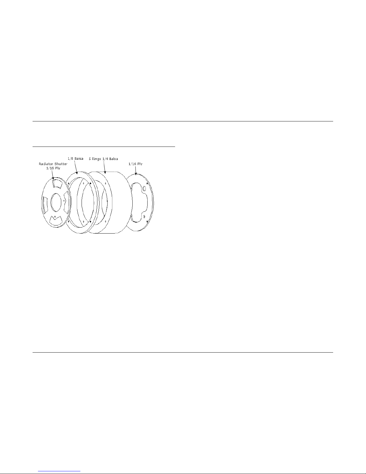
Glue the rear 1/16 ply mount C3, the five 1/4 balsa
rings C2, and the 1/8 balsa ring C1 together in the order
shown above. Use 1/16 wood dowels (cocktail skewer or
toothpick) to hold parts in alignment. The dowels should not
extend through the 1/8 balsa ring.
Sand the assembled cowl to shape. You can use a
long bolt and nut as a spindle to mount the assembled cowl in
a drill press.
Cut the centers out of the balsa and ply rings. This will
be easier to do if you temporarily remove the 1/16 ply mount
C3.
Glue the radiator shutter (forward 1/16 ply part) inside
the front 1/8 balsa ring.
If you are using outrunner motors, the cowl assembly is
complete. Skip forward to step 10.
Cut the two 1/4” square hardwood motor mount beams
to length, and slip them into their mounting holes on N1 and
N2.
 Loading...