

Manzanita Micro PFC-50, PFC-75 Owner's Manual
PFC-50 & PFC-75
Owner’s Manual
©2012 Manzanita Micro LLC
The information date is: 02/10/2012
Charger
Rev 2.1
1

CONTENTS
GENERAL OVERVIEW………………………………………………………5
KEY FEATURES LIST………………………………………………………. 6
DIMENSIONS AND SPECIFICATIONS…………………………………… 7
CHARGER OPERATION…………………………………………………….8
- Photo of Charger Face With Callouts…………………………………. 8
- Volts Trim ~ Adjusting the Peak Charging Voltage Limit………….. 9-10
- Reg Bus Port ~ Basic Info……………………………………………….. 11
- Descriptions of Panel LED Indicators………………………………… 11-12
- Dip Switches……………………………………………………………….. 13
WIRING YOUR MANZANITA MICRO CHARGER………………………..14
- Connecting the Charger to the Battery Pack………………………… 14
- Connecting the Charger to the Wall…………………………………… 17
- PFC50 Wiring………………………………………………………………. 14
- PFC75 Wiring………………………………………………………………. 16
- Running Your PFC Charger on DC instead of AC…………………... 19
- 120V Standard Adapter Drawing for PFC50 & PFC75……………….20
- Reg Bus Wiring & Pin-out Info………………………………………….. 21
- Reg Bus Cable Construction……………………………..……………...22
- New 8A Control Board Additional Features…………………………...24-25
- AC Line Power Meter Options………………………………….………...26
CONTACTING MANZANITA MICRO....………………………….………...27
2

READ THIS FIRST!
ADDITIONAL NOTES AND PRODUCT MANUALS AVAILABLE AT: www.manzanitamicro.com
CAUTION: Your PFC-Charger uses High Voltage DC and AC electricity.
The chargers have been designed to be adaptable for use with many different battery types and
voltages. It is the responsibility of the end user to properly set up the charger making necessary
adjustments so that it can work with their unique system. With such flexibility, the charger is intended
to be able to be configured for use in various experimental applications and Manzanita Micro LLC and
its employees, contractors and affiliates cannot be responsible for any damages due to any Manzanita
Micro product that has been set up by the end user. There are too many variables out of Manzanita
Micro's control. It is entirely the responsibility of the end user to make sure that they are competent to
work with potentially lethal voltages and that they have a solid understanding of how to safely
integrate the Manzanita Micro product(s) into their application.
The information contained in this warning and in the product manuals is intended to be used as a
guide to better familiarize oneself with the product(s) but Manzanita Micro has no control over how the
information will be used or not used and cannot possibly foresee all possible configurations that a
user may come up with.
•Do not work on the PFC-Charger or attempt to use one if you are not qualified
•Observe the owner’s manual procedures and cautions
•Avoid working on an electric vehicle while it’s charging
•ALWAYS assume that high voltage is present
•Use electrical tape or another suitable insulator to cover all exposed high voltage connection
points and also cover metal tools to reduce the likelihood of the tool completing a current path
•DO NOT USE A CONDUCTIVE METAL SCREW DRIVER TO ADJUST THE VOLTS TRIM ON YOUR
CHARGER!
•When using a Manzanita Micro BMS with older charger models the Regbus GND return line is
NOT ISOLATED FROM MAIN BATTERY PACK NEGATIVE! Never touch or create a path from
the regbus conductors to any battery in the pack or serious shock could occur!
•Disconnect all other non-isolated chargers from the battery pack and from line current
•Make sure there is NO PATH TO GROUND or the vehicle chassis from any portion of the main
battery pack.
•Make sure the polarity is correct BEFORE you hook the battery pack to the charger cable.
•Make sure the area around and above the workplace is clean and dry
•Do not compress or set heavy objects on the charger. Deforming the case can result in shorting
the internal circuit boards to the case.
•DO NOT operate this charger unloaded! A battery pack must always be plugged in to the DC
output plug from the charger if it is turned on!
FAILURE TO HEED THESE WARNINGS AS WELL AS THE BATTERY WARNINGS ON THE BACK OF
THIS SHEET MAY RESULT IN PHYSICAL INJURY, DEATH, OR DAMAGE TO YOUR CHARGER, BMS OR
OTHER EQUIPMENT WHICH WILL NOT BE COVERED UNDER YOUR WARRANTY.
IT IS RISKY TO PLUG ANY BATTERY CHARGER INCLUDING MANZANITA MICRO CHARGERS INTO
GENERATORS. MANY GENERATORS ESPECIALLY THE LESS EXPENSIVE GENSETS DO NOT HAVE A
CLEAN, WELL REGULATED, PREDICTABLE OUTPUT AND THEY CAN CREATE HIGH VOLTAGE
SPIKES WHICH CAN DAMAGE COMPONENTS IN THE CHARGER. SOME CUSTOMERS HAVE HAD
SUCCESS WITH HIGH END PURE SINE WAVE COMPUTER GRADE GENERATORS BUT MANZANITA
MICRO CANNOT RECOMMEND A SPECIFIC MODEL AT THIS TIME AND CANNOT BE RESPONSIBLE
FOR ANY DAMAGE DUE TO GENERATORS OR OTHER POWER SOURCE PROBLEMS.
3
BATTERY NOTES!
CAUTION: Your PFC-Charger can output over 400 volts DC and many thousands of watts of electrical
power! It is imperative that the end user have a clear understanding of how to safely charge their
particular battery!
Manzanita Micro sells very flexible charging systems that can be used with almost any type of battery.
Manzanita Micro chargers are used in all sorts of applications. Manzanita Micro LLC cannot be held
responsible for any problems arising from the improper use of the charger or BMS with a battery pack
or other storage device.
FAILURE TO OPERATE BATTERIES OR OTHER ENERGY STORAGE DEVICES WITHIN THEIR SAFE
DESIGN PARAMETERS CAN RESULT IN CATASTROPHIC FAILURES INCLUDING BUT NOT LIMITED TO
FIRE, EXPLOSION, TOXIC FUMES, EXCESSIVE HEAT, THE RELEASE OF CAUSTIC OR POISONOUS
MATERIALS, PHYSICAL DEFORMATION AND VARIOUS OTHER POTENTIALLY LETHAL SITUATIONS.
ALWAYS WEAR EYE PROTECTION AND OTHER PROPER PERSONAL PROTECTIVE EQUIPMENT
WHEN WORKING AROUND BATTERIES. UNDERSTAND THE SAFE HANDLING INSTRUCTIONS AND
IMPORTANT SPECIFICATIONS OF YOUR PARTICULAR BATTERY PACK OR ENERGY STORAGE
DEVICE! IF EVER IN DOUBT, CONTACT THE BATTERY MANUFACTURER!
NEVER ALLOW MORE THAN ONE PERSON TO WORK ON THE SAME HIGH VOLTAGE SYSTEM OR
BATTERY PACK AT THE SAME TIME. IF TWO OR MORE PEOPLE ARE TOUCHING PARTS OF THE
SYSTEM IT IS EASIER TO COMPLETE A CIRCUIT AND CAUSE ELECTROCUTION. WHILE MULTIPLE
PEOPLE SHOULD NEVER WORK ON THE SAME SYSTEM, IT IS ADVISABLE TO HAVE MORE THAN
ONE PERSON NEAR BY WHENEVER ONE PERSON IS WORKING WITH HIGH VOLTAGE.
NEVER TOUCH ANYBODY WHILE THEY ARE WORKING ON A HIGH VOLTAGE SYSTEM OR BATTERY
PACK! IF SOMEONE IS GETTING SHOCKED AND CANNOT LET GO OF THE ELECTRICAL SOURCE,
THE EXTRA PERSON CAN SAFELY DISCONNECT THE ELECTRICAL SUPPLY AND/OR GET HELP. IF IT
IS NOT POSSIBLE TO DISCONNECT THE SUPPLY, AND IF PROPERLY INSULATED EQUIPMENT IS
AVAILABLE THEN THE EXTRA PERSON MAY USE A DEVICE SUCH AS AN INSULATED HUMAN HOOK
TO PULL THE PERSON BEING SHOCKED AWAY FROM THE ELECTRICITY. NEVER EVER TOUCH
SOMEONE WHO IS BEING SHOCKED!
Manzanita Micro chargers are very powerful. Do not exceed the safe charging rates as specified by
your particular battery manufacturer!
Manzanita Micro chargers are capable of outputting any charging voltage from 12 to 450 volts DC. It is
up to the end user to understand the safe voltage range for their particular battery, cell, battery pack or
other energy storage device. Do not exceed the peak charging voltage given by the battery
manufacturer. Carefully read the Manzanita Micro Owner’s Manual(s) for your particular product(s). For
chargers, it is essential to understand how to properly set the peak charging limit using the volts trim
potentiometer. For BMS (Battery Management Systems) it is imperative that the user makes sure that
the BMS is properly set to match the safe and appropriate parameters for their particular make and
model of battery.
Ask the battery manufacturer for all parameters on how to safely charge their batteries and do not use
any charger or BMS if you cannot properly tune the equipment to meet those specifications.
4

PFC-50 / 75 BATTERY
CHARGER MANUAL
Rev 2.1
General Overview
The Manzanita Micro PFC chargers are a unique group of powerful, efficient battery
chargers. The chargers will run off any voltage from 100 up to 240 volts AC. The
chargers can be set to run automatically when plugged in, yet they also have far
more user adjustable functions than other electric vehicle chargers. Every model is
user adjustable to charge batteries from 12 to 450 Volts DC. The PFC-50, PFC-50B
and PFC-75 are all power factor corrected. The PFC-75 comes standard with an AC
input current display and rear panel mount Anderson Power Pole connections. With
so much flexibility and models from 20 to 75amps, your PFC charger may be the
last charger you ever need to buy.
Speed and Efficiency
The essential ingredient for fast recharge times is to deliver high power to the
battery. The key to polite opportunity charging is to be able to share outlets with
other equipment and make efficient use of limited current. The Manzanita Micro
PFC line of chargers has an adjustable current throttle knob to allow the chargers to
be turned down to operate on very limited power sources. Even the venerable PFC75 can easily run at reduced output from a 110 volt source. Efficiency and power
factor are both better than 0.9.
What does the PFC mean?
In the Manzanita Micro chargers PFC stands for Power Factor Corrected. This
means that current and voltage are drawn in unity, (ie: current is drawn with unity to
the incoming line voltage).
5

PFC-50/75 SERIES
CHARGER FEATURES
•Power Factor Corrected
•Every charger easily runs on any single phase AC voltage from 100 to 240V
•Easy ‘Amps’ adjustment knob allows users to quick-tune the charger to pull
maximum amps out of whatever it is plugged into
•User adjustable peak charge voltage allows users to adapt charger to any
battery voltage from 12 to 450 volts
•Up to 18,000 watts of power from a unit that weighs less than 50 lbs (22kg)
•Reg bus port for easy integration with Manzanita Micro BMS (also compatible
with other Battery Management Systems)
•Self regulating thermal protection
•Active variable speed fan cooling
•Input line current meter option
•Rear panel mount Anderson Power Pole I/O connections on PFC-75 (this is
optional for the PFC-50 or PFC-50B)
•Adjustable absorption phase (end of charge) timer function
•Ability to enable auto restart mode
•Ability to enable timed charging mode
•Float charge option possible with new 8A control board
6
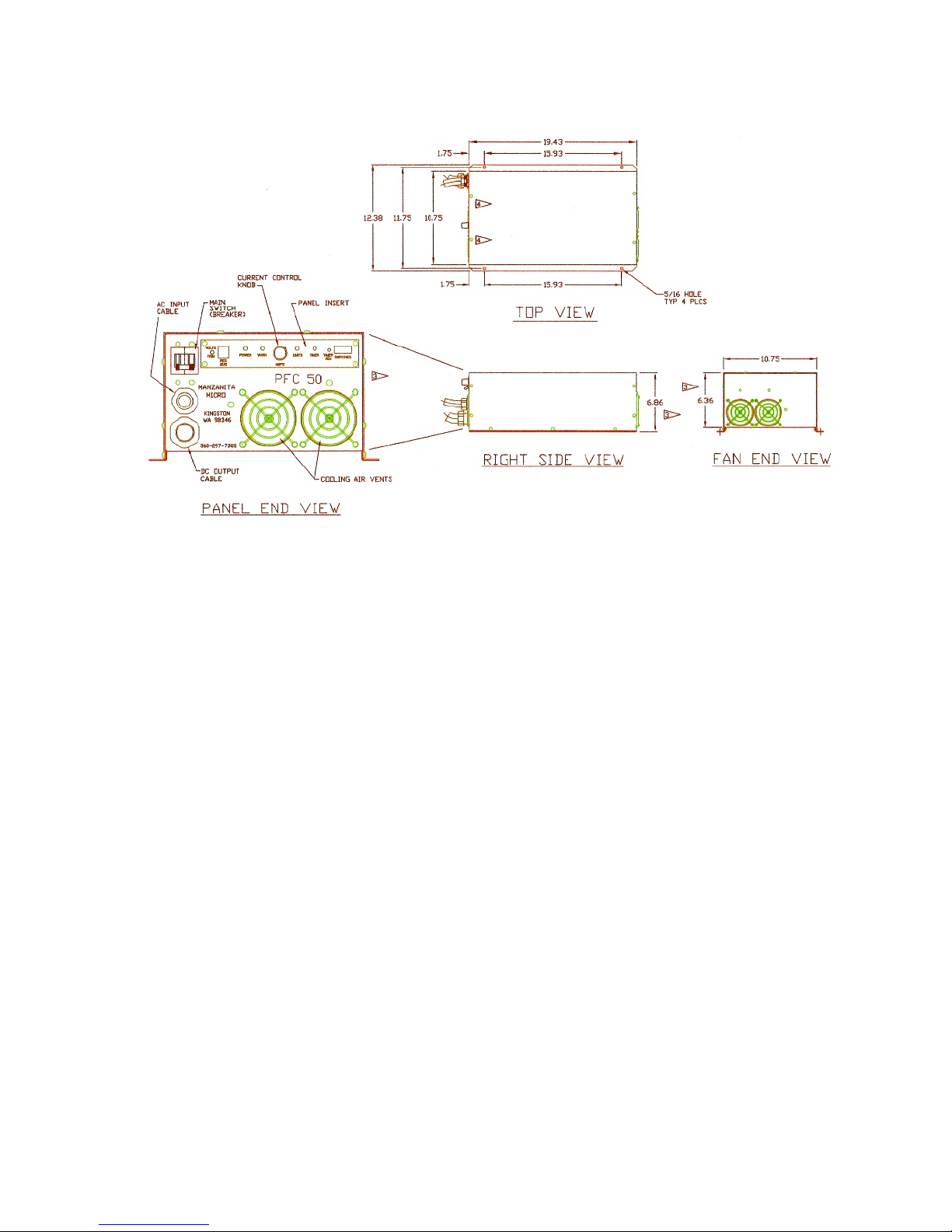
Dimensions and Specifications
The PFC-50 and 75 series chargers weigh approximately 42 pounds (19 kg)
The outermost dimensions including foot flanges and front amps knob are
approximately 22” L x 12.5” W x 7” H (559mm x 318mm x 177mm)
Allow at least 25” total length (635mm) to include the power cables
Input Voltage Range : 100 to 240VAC 40-80Hz computer grade pure sine wave
Output Voltage Range : 12 to 450VDC ( +/- 1 volt )
Operating Temp Range : -20° F to +120° F ( -28.8° C to +48.8° C )
Power Consumption : Up to 12.0kW ~ PFC-50 and PFC-50B / 18.0kW ~ PFC-75
The 50 in PFC-50 is indicative of the number of amps that the charger is rated to
draw from the AC line. A PFC-75 can draw up to 75 amps. Unlike some other
chargers, this is the rated continuous load and all units are thoroughly tested to their
rated limits before leaving Manzanita Micro. The PFC-75 model includes a current
meter on the front which displays the amount of current (amps) that the charger is
drawing from the AC line. This allows the user to tune the charger precisely for the
maximum allowable amps for the outlet they are plugged into.
The charger can be mounted in any orientation as long as it has adequate airflow
and is protected from sucking in moisture and debris. All chargers are designed to
automatically cut back current when they exceed their temperature limits. If the
yellow limits light starts blinking and power is reduced, it is likely more airflow is
needed. The fans push the air out through the front of the charger therefore,
mounting the unit such that the control face is pointing upward this is probably the
most efficient since heat rises. It is important to use properly sized bolts for all four
mounting holes in order to mount the unit. Grade 5 or Grade 8 fasteners are the
7
best and stainless steel or other quality plating is preferable to decrease corrosion.
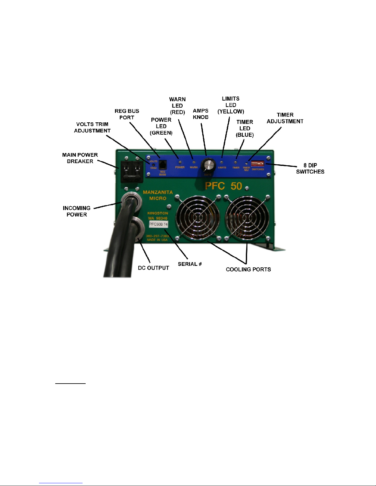
Charger Operation
figure 02. Charger Layout (see final section for new 8A layout)
Turning the Charger On and Off
There is an ON/OFF Breaker to the left of the blue user control panel at the top of
the charger. This breaker is the main switch to turn the charger on or off. If ever
there is a concern while charging first shut off this breaker switch.
NOTICE! DO NOT unplug the Anderson connectors (DC line) from your charger
while it is charging! If the battery pack is disconnected while the charger is putting
out power the charger can be damaged. Failure to heed these warnings may
result in significant internal damage to the charger which is not covered under
your warranty!
8

User Control Panel
The user interface panel is the long blue panel with yellow text near the top of the
PFC charger. The main things most users need to be concerned with are the LED
indicators, the VOLTS TRIM and the adjustable AMPS knob. Below are
explanations of each feature in order from left to right. Refer to figure 02 for specific
locations.
“VOLTS TRIM”
This controls the peak DC voltage ceiling that the charger will allow the batteries to
reach before limiting the current. Unless specified otherwise, the voltage limit is
specifically calibrated and set by Manzanita Micro to 191 Volts (for a 156V nominal
pack.) In the event that adjustment is desired, please follow the instructions below.
Starting in 2010, a special insulated screw driver for adjusting the volts trim is
shipped with each new Manzanita PFC charger.
NOTICE! Always use an appropriately sized insulated screw driver when adjusting
the voltage trim potentiometer. Suitable drivers are available for purchase from
Manzanita Micro or other electronics components manufacturers. (Mouser part #:
594-8T000, Vishay/Spectrol Adjust Tool, www.mouser.com)
figure 03. Adjustment Tool # 008T000
NOTE: If the battery pack is especially cold for any reason such as outdoors in a
cold season or climate, the peak charging voltage threshold may need to be raised
in order to assure a complete charge. This is especially true for lead acid batteries.
Many users turn the volts trim to the absolute maximum safe level for the batteries
during the winter and then back down to normal during the summer months. Always
consult your battery manufacturer for information on the peak “fully charged” voltage
specifications and how they change based on temperature.
NOTE: The peak voltage regulation set point on a Manzanita Micro charger is
accurate to within 5 volts or less. Follow the “Volts Trim Calibration” instructions
below and make the initial adjustment with the amps knob completely down so that
no current is flowing. Gradually turn up the amps knob and nudge the volts trim
potentiometer up accordingly. Use caution on the first charge cycle and make sure
to check that the point at which the charger volts trim limit is reached is really the
correct voltage for your specific batteries.
9
 Loading...