

Page 1
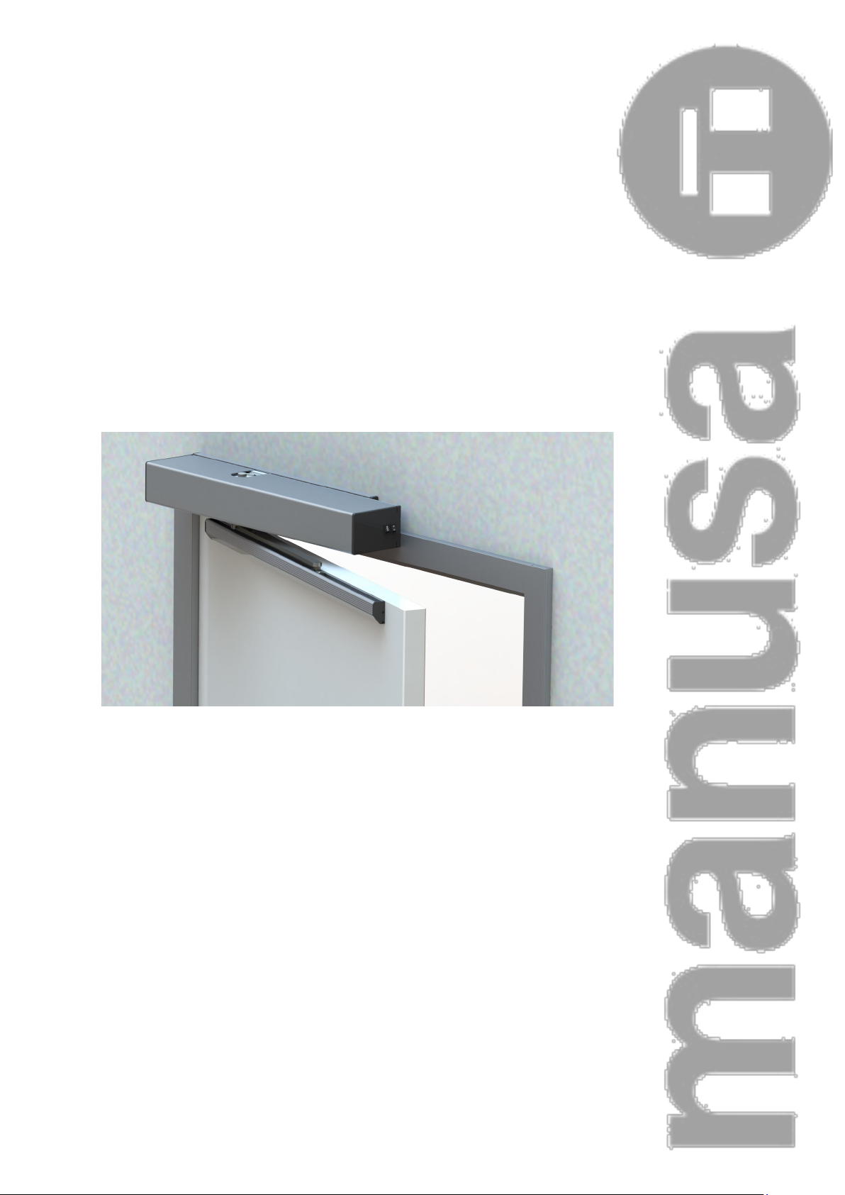
Installation Manual
VECTOR Operator
Page 2
1
D00619EN - v0 VECTOR OPERATOR - INSTALLATION MANUAL
TRANSLATED DOCUMENT
0 CONTENTS
Read thoroughly all of these instructions before installing
the operator
Keep this manual in a safe place for future reference
This manual is meant exclusively for professional installers.
Installation Manual
VECTOR
1. PRODUCT IDENTIFICATION
1.1 Product Description
1.2 Symbol Description
1.3 Versions
1.4 Product EC Marking
1.5 Noise Statement
1.6 Radiation, Gas, Fumes and Dust Produced
by the Machine
1.7 Use in Flammable and/or Explosive Environments
1.8 Accessories
2. TRANSPORTATION, STORAGE AND MAINTENANCE
2.1 Machine Delivery Conditions
2.2 Transport Conditions
2.3 Storage Conditions
3. TECHNICAL DATA
3.1 General Dimensions
3.2 Technical Specifications
3.3 Low Energy
3.4 Operation
3.4.1 ON-OFF Switch
3.4.2 Mode Selection Switch
3.5 Installer Instructions
3.6 Decommissioning, Dismantling and Removal
3.7 Intended Use and Uses that Should be Avoided
3.8 Application Limitations
4. PRE-INSTALLATION
4.1 Training Requirements for Installation Technicians
4.2 Physical and Environmental Requirements
4.3 Electrical Pre-installation Requirements
5. INSTALLATION
5.1 Type of Arm that Can Be Installed
5.2 Installing the Operator
5.3 Positioning Levels for the Fixing Holes
5.4 Extendable Rigid Arm Installation
5.4.1 Rigid Arm and Guide Installation
5.5 Installing the Pushing Articulated Arm
5.5.1 Attaching the Arm to the Leaf
5.6 Spring Adjustment
5.7 Selecting Breaking Level without Power
5.8 Testing Operations
5.9 Connecting to the Power Supply
5.10 VECTOR Electronic Card
5.11 Electronic Connections
5.12 Arm-Type Selection
5.13 Connecting the Controls/Inputs
5.14 Connector to Auxiliary Outputs
5.15 Installing and Acquiring the Sensors
5.16 Dip-Switch Management
5.17 Display Management
6. COMMISSIONING
6.1 Start-up
6.2 Management and Use
6.2.1 Operational Logic Settings
6.2.2 Management of Electronic Locks
6.2.3 Program Switch Connector
6.2.4 External Peripherals Connectors (15 VDC)
6.2.5 Double Vector Connection and Use
6.2.6 Interlocking Connection and Use
6.2.7 Connection to a PC
6.2.8 Normal Stop and Emergency Stop
7. SAFETY
7.1 General Safety Instructions
7.2 Required Personal Protection Equipment
7.3 Identifying Dangerous Areas in the Machine
7.4 Risk Evaluation
7.5 Safety Regulations
8. MAINTENANCE AND INSPECTION
8.1 General Maintenance to be Performed by the User
8.2 Maintenance Tasks Exclusively Reserved for
the Manufacturer
9. TROUBLESHOOTING
10. APPENDIXES
10.1 EC Declaration of Conformity
10.2 Installation Check-list
10.3 Maintenance Book
10.3.1 Frequency of Interventions
10.3.2 Actions Log
10.4 Notes
Page 3
2
D00619EN - v0 SWING OPERATOR - INSTALLATION MANUAL
CARACTERÍSTICAS MECÁNICAS
1 PRODUCT IDENTIFICATION
The manusa VECTOR swing operator has been especially designed to make fast, safe and controlled access of persons to
all types of facilities possible.
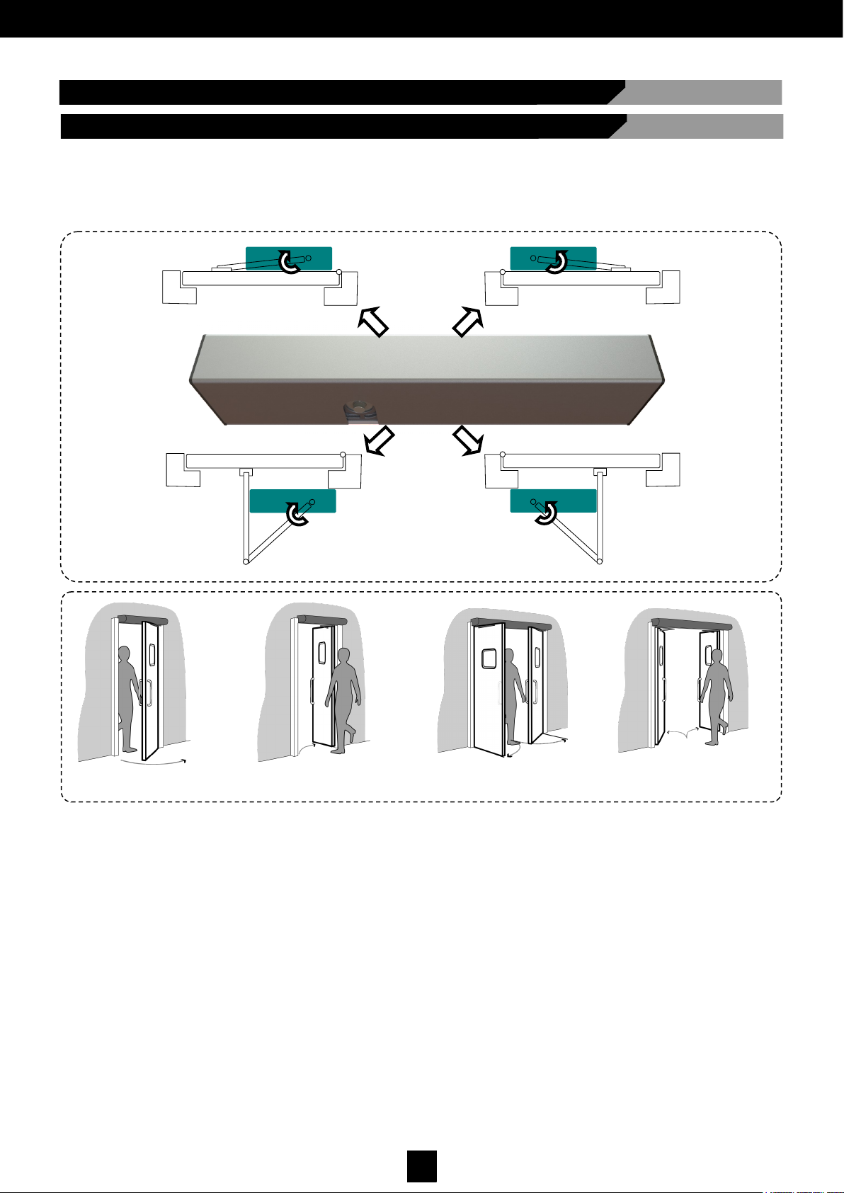
It is an operator for automatic swing doors with high traffic flow, available with dragg or push arms for single-slide and biparting door versions.
VECTOR is an advanced electromechanical operator used for the automation of any type of new or existing swing door.
It is a highly-efficient, high-performance operator, especially designed for intensive use, as it can automate both light and
very heavy doors.
manusa VECTOR is also recommended for hermetic doors for clean rooms, and for environments with strong winds,
thanks to its specific operating modes.
Other main features:
- Compact design, with minimum aesthetic impact
- Formal and attractive design with pleasant lines
- Door closing by means of an motor-assisted spring in normal operation
- Door closing by means of a spring in case of power supply failure
- Available modes for Low Energy and Push&Go activation
- Easy installation and monitoring thanks to its built-in double display
Single + Pull arm Single + Push arm Bi-parting + Push arm Bi-parting + Pul arm
1.1 Product Description
Page 4
3
D00619EN - v0 SWING OPERATOR - INSTALLATION MANUAL
This manual details all the basic instructions for assembling the automatic door. Read it thoroughly and, when in doubt,
contact the Technical Support Department (see back of the manual).
For your own safety, adhere at all times to all the technical instructions detailed in this manual. manusa accepts no
responsibility for damages and faults derived from not complying with these instructions.
Finally, we would like to thank you for your trust in acquiring a product from the manusa range, a company with more than
50 years experience designing, manufacturing and installing automatic access systems.
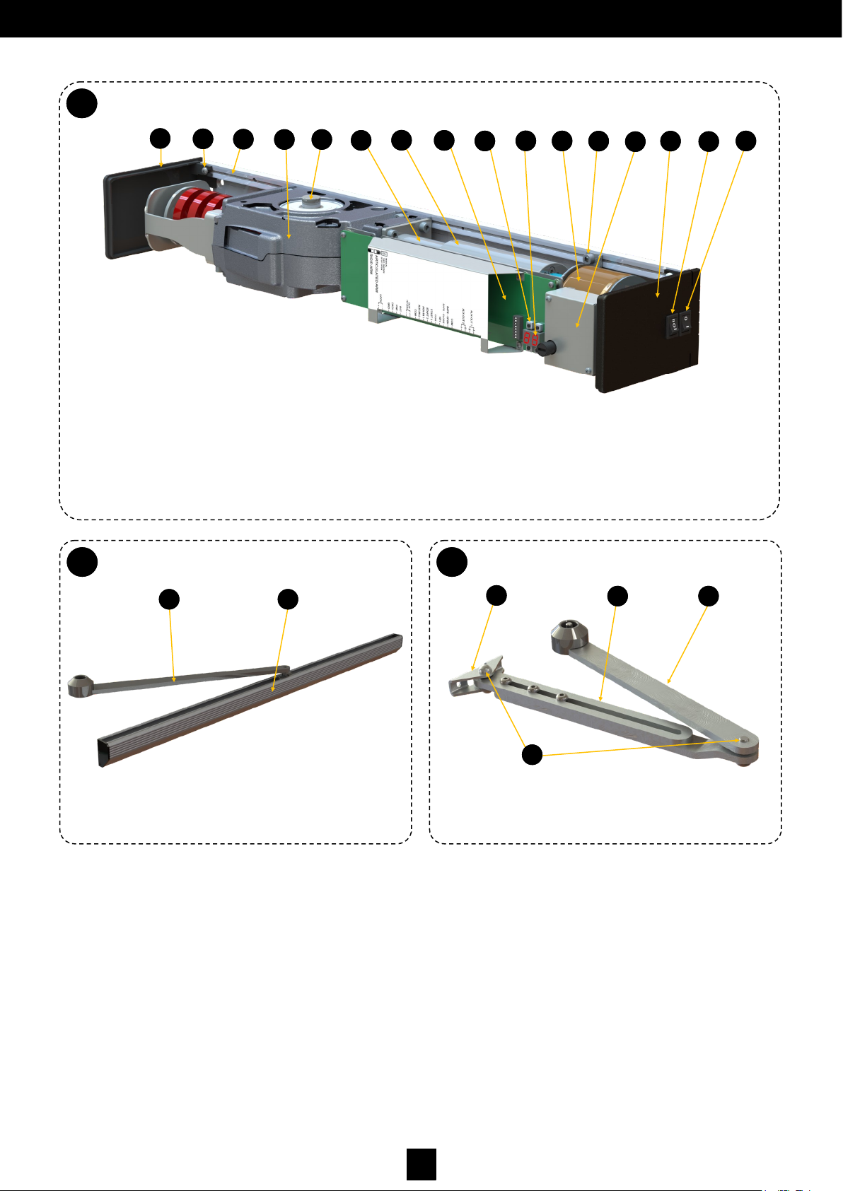
Drag arm
B
1.1
VECTOR Swing Operator
A
1.1
Push arm
C
1.1
17. Drag arm
18. Drag guide profile
19. Arm-to-leaf anchor
20. Joints
21. Adjustable-depth plate
22. Push arm
17 18
19
21 22
20
2
3
1
4 5
6
7
8
9
10
11
13
14 12
15
16
1. Blind side cover
2. Cover screws
3. Main chassis profile
4. Re-send mechanism
5. Axis with upper and lower outputs
6. Gear
7. Motor
8. Electronics
9. Navigation buttons
10. Operator control display
11. Transformer
12. Installation screws
13. Filter
14. Side cover
15. Mode selection program switch/ Mode switch
16. ON-OFF button
Page 5

4
D00619EN - v0 SWING OPERATOR - INSTALLATION MANUAL
The symbols that appear in this manual and/or in the machine are listed below:
1.2 Symbol Description
ELECTRICAL HAZARD. The inside of the machine must
not be manipulated unless it has been previously
disconnected from the power supply.
DANGER. Improper use may cause injuries to people
and damage the machine.
IMPORTANT WARNING. Strictly adhere to the
indicaons provided with this symbol.
OPTIONAL. These elements are oponal; they will be
included in the box depending on the order placed.
LEFT
Side Opening
BI-PARTING RIGHT
Side Opening
):
1.3 Versions
Both the operator and the two arm versions (dragging and pushing) are universal for any leaf typology: bi-parting, left
and right opening.
It is available in the following transmission arm configurations, in single or bi-parting variants:
Drag arm: attached to the wall on the same side as the hinges (see picture).
Push arm: attached to the wall on the opposite side as the hinges (see picture).
Page 6
5
D00619EN - v0 SWING OPERATOR - INSTALLATION MANUAL
CARACTERÍSTICAS MECÁNICAS
1.8 Accessories
machines are compatible with the range of accessories. Technical Department shall perform an
evaluation for any integration with machines from other manufacturers.
1.4 Product EC Marking
La máquina debe disponer de una etiqueta de marcado similar a la de la
imagen. De no ser así, informar de la incidencia al Servicio Asistencia
Técnica (ver dorso del manual).
CARACTERÍSTICAS MECÁNICAS
1.7 Use in Flammable and/or Explosive Environments
The machine described in this manual has not been designed to operate in flammable and/or explosive environments.
1.5 Noise Statement
The weighted acoustic pressure level of emissions A is below 70 dB.
CARACTERÍSTICAS MECÁNICAS
1.6 Radiation, Gas, Fumes and Dust Produced by the Machine
machines do not produce any type of radiation, gas, fumes or dust.
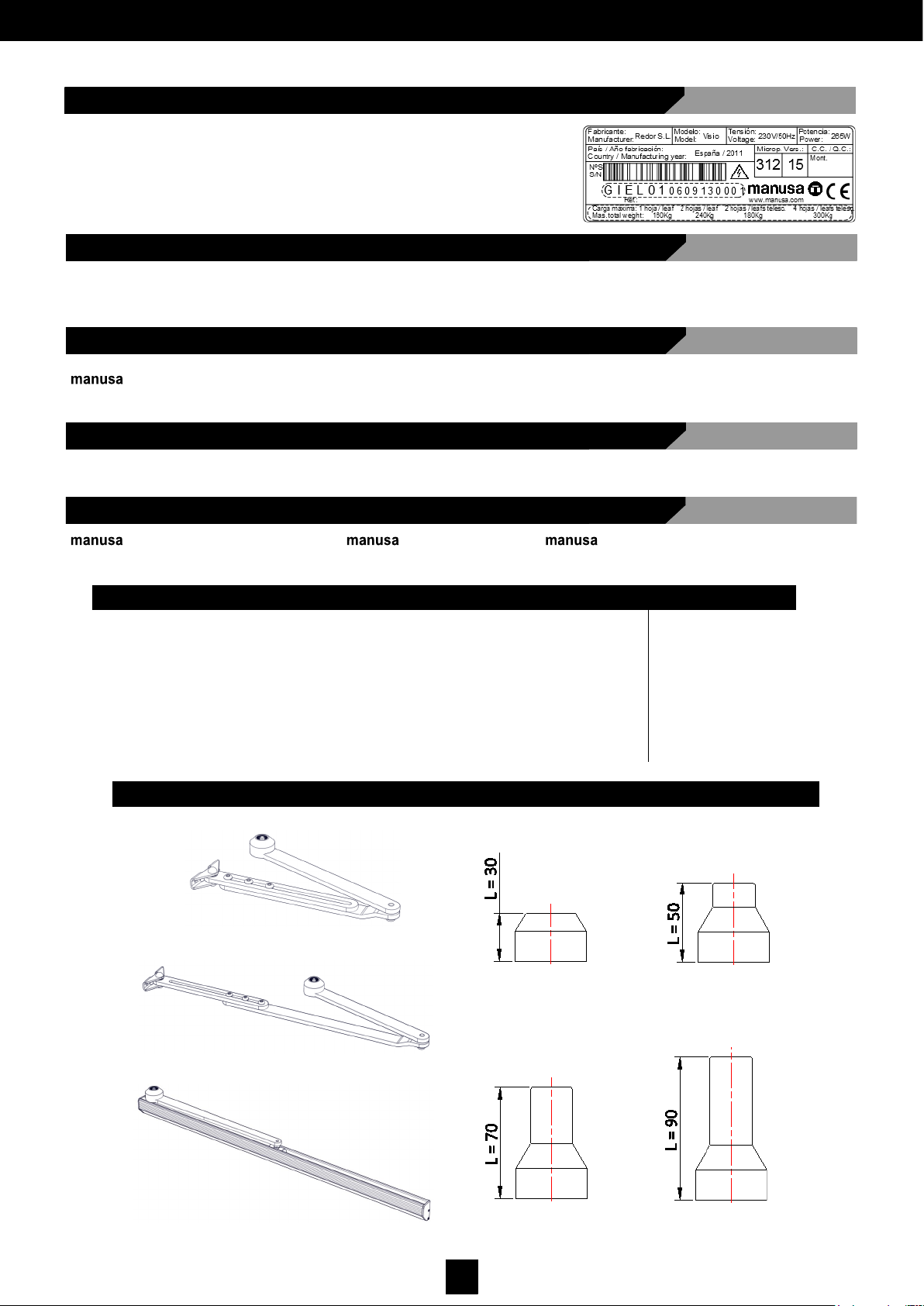
ARMS
- Short push arm.
- Long push arm.
- Pull arm.
AXIS EXTENSIONS
- 30mm axis extension. - 50mm axis extension.
- 70mm axis extension. - 90mm axis extension.
WIRED RANGE WIRELESS RANGE DETECTION CONTROL / OTHER
- Push button
- Elbow push button
- Key switch
- Proximity reader
- Keypad
- Autonomous print
reader
- Push button
- Elbow push button
- Key switch
- Keypad
- Remote control
- Hands-free access
identifier
- Movement sensor
- Reopening photocell
- Standard presence sensor
- Recessed presence sensor
- Unsupervised movement and pres-
ence sensor
- Supervised movement and pres-
ence sensor
- Touchless switch
- Emergency stop
- Buzzer and/or
warning light
Page 7
6
D00619EN - v0 SWING OPERATOR - INSTALLATION MANUAL
CARACTERÍSTICAS MECÁNICAS
2 TRANSPORT, STORAGE AND MAINTENANCE
2.1 Machine Delivery Conditions
is in charge of the initial delivery of the machine. Please make sure that all the parts and components arrive in good
condition: that they have not been tampered with, that there is no item missing from the list on the delivery note, that it did not
get wet or suffer from damage caused by the environment. If this is not the case, please log this in writing in the appropriate
delivery note and contact .
2.2 Transport Conditions
For subsequent transportation, the machine must always travel conveniently packaged and protected from the elements.
CARACTERÍSTICAS MECÁNICAS
2.3 Storage Conditions
If the machine is not going to be installed immediately, make sure it is stored in an area that meets the following criteria:
• A safe place, protected from impact and out of reach from people who are not to use the product.
• The machine needs to rest on a flat, smooth and resistant surface, maintaining the same distribution as in the transport
container or vehicle.
• A location protected from corrosive environments, from the elements, damp, oils, fumes, etc.
OTHER
- Intermediate cover kit - Cover to measure
3. TECHNICAL DATA
CARACTERÍSTICAS MECÁNICAS
3.1 General Dimensions
130
89
94
Lop = 665
Lop = 675
Fig. 1.
Page 8
7
D00619EN - v0 SWING OPERATOR - INSTALLATION MANUAL
The manusa VECTOR swing operator offers high-end kinematic performance in the industry:
OPERATING LIMITS
10 years
ELECTRICAL FEATURES
Power supply
230 V 50Hz—110 V 60 Hz
Nominal power
85W
Max. output shaft torque
45Nm
Power supply to external devices
15VDC—12W Max.
Operating temperature
De -10°C a 50°C
Servicing
Continuous
APPLICABLE STANDARDS
Low Voltage
2014/35/CE
Electromagnetic Compatibility
2014/30/CE
Construction Products
2011/305/CE
Machine Safety
2006/42/CE
Automatic Door Use Safety:
EN 16005
MECHANICAL FEATURES
Dimensions (Height x Width x Length) (Fig.1)
89x130x675mm (1 leaf) 89x130x2800mm
(max. 2 leaves)
Maximum leaf weight
250 Kg (See fig.2)
Opening time
3s (70°/s) ÷ 6s (20°/s)
Closing time
4s (40°/s) ÷ 15s (10°/s)
Closing force (second in 1154)
EN4 ÷ EN6 (See fig.18)
Maximum opening angle
110º
Width of the door leaf
700 ÷ 1400mm
Anti-crushing protection
Automatically limits force when obstacles are present
Weight
Approx. 11kg.
Degree of protection
IP40
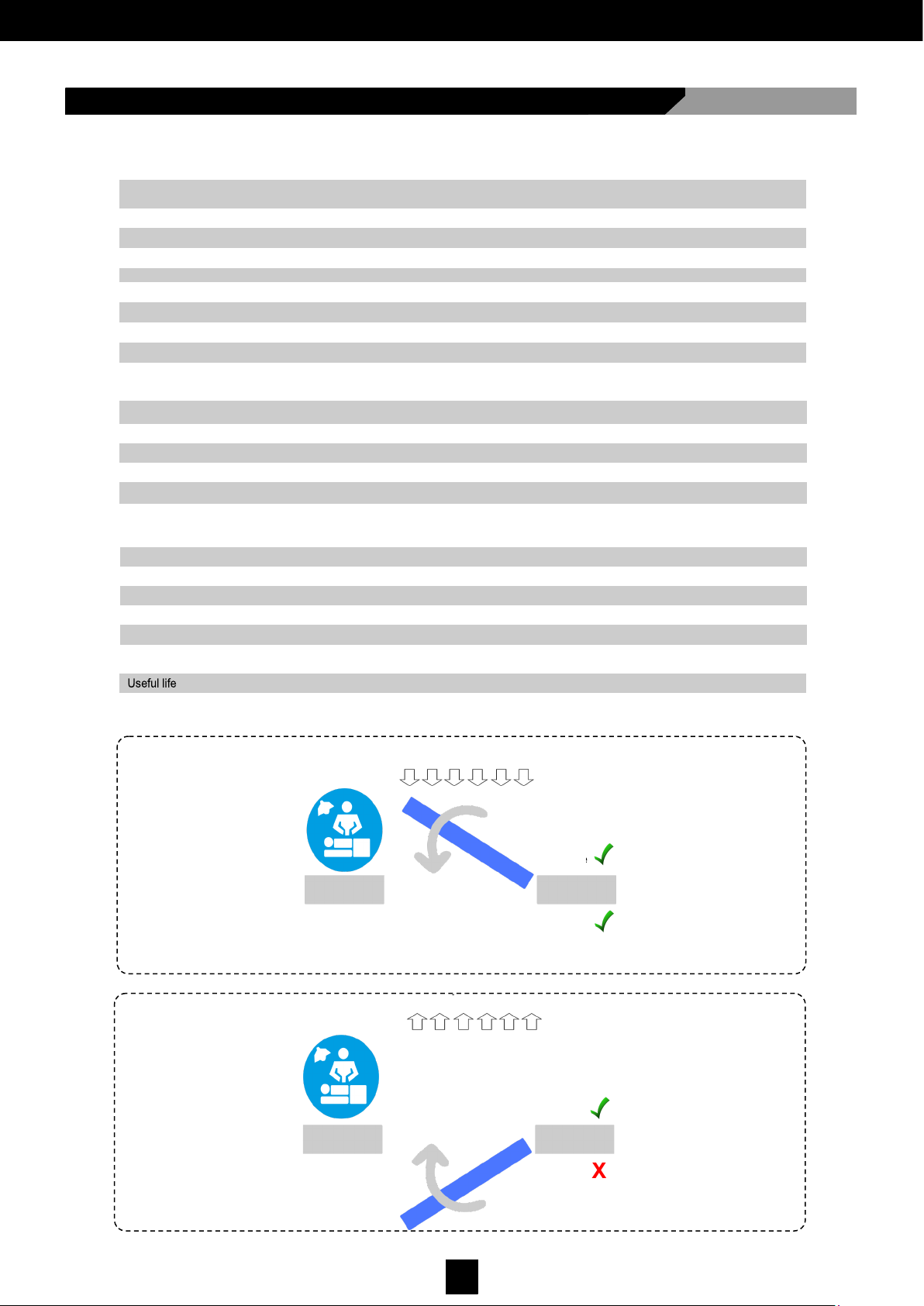
3.2 Technical Specifications
Up to +35Pa
Up to +30Pa
X
Up to –100Pa
It does not open from –10Pa
WORKING PRESSURES
NEGATIVE PRESSURE -
POSITIVE PRESSURE +
Dragging
Pushing
Dragging
Pushing
Page 9
8
D00619EN - v0 SWING OPERATOR - INSTALLATION MANUAL
3.5 Installer Instructions
3.4 Operation
manusa doors are designed to operate automatically. Manual operation is only intended in the case of an emergency and to
carry out cleaning, maintenance and adjustment tasks.
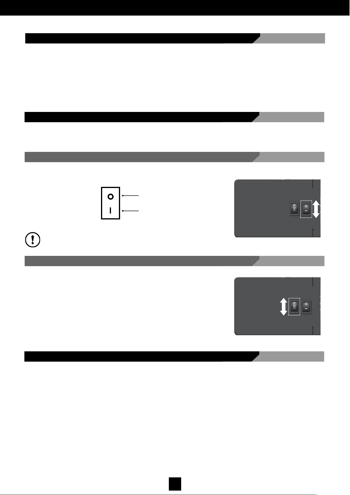
3.4.2 Mode Selection Switch
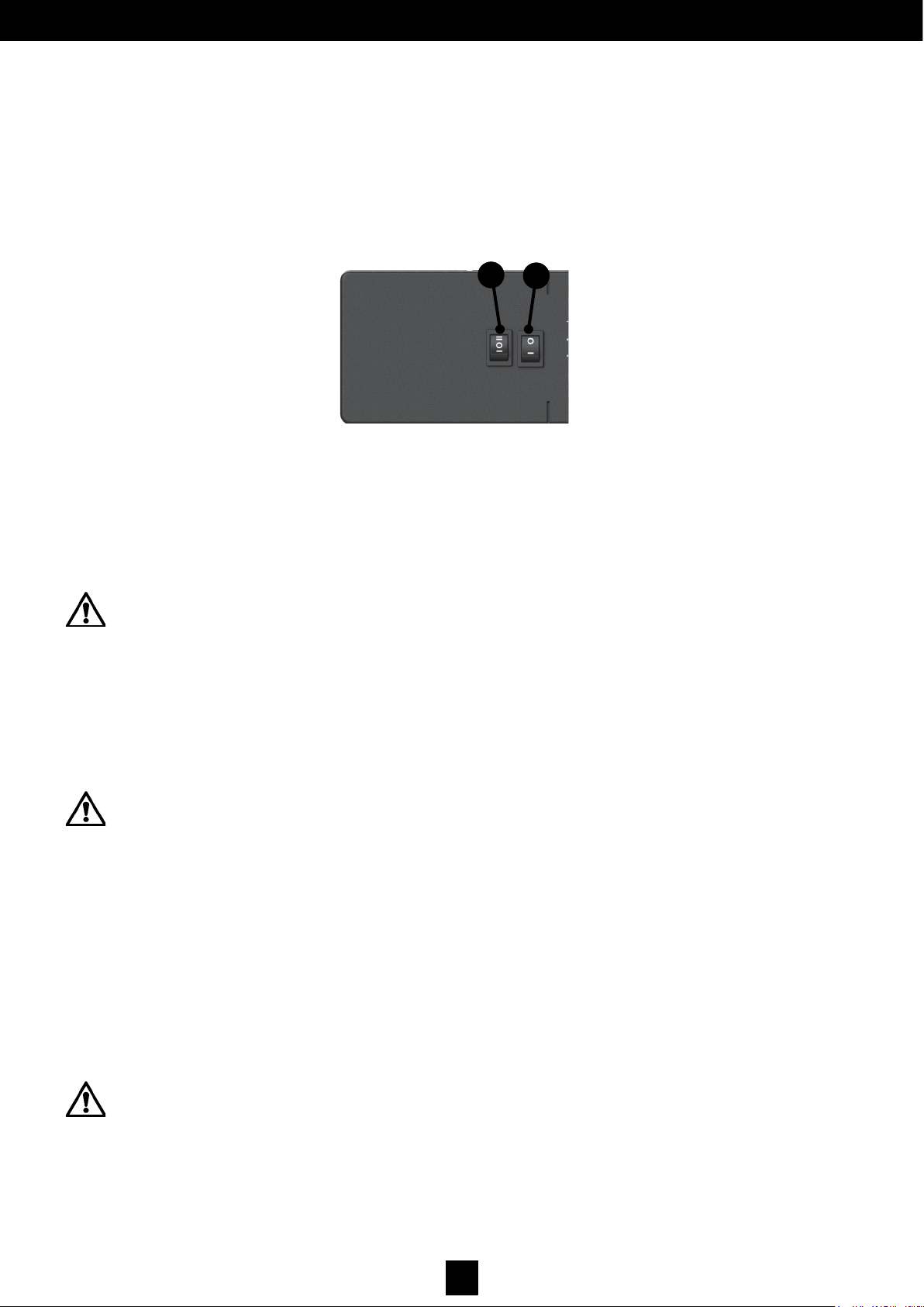
This switch is located on the head of the operator, next to the ON-OFF switch. It
enables mode selections:
I Manual
0 Automatic (two radars)
II Stop open
The installation of external switches voids the operation of this mode selection switch.
3.4.1 ON-OFF Switch
A switch that turns the operator on and off:
Off
On
3.3 Low Energy
The operator can be regulated in Low-Energy mode in accordance with standard EN16005, thanks to the following
features:
- Reduced dynamic force on the door threshold
- Restricted operator force and limited speed
The installer should check the Low-Energy installation conformity with applicable standards. Protection of the closing
edge should be evaluated individually.
• Follow the instructions carefully when installing the operator.
• This product has been designed and manufactured to be used exclusively for the purposes indicated in this manual.
Any other use not expressly indicated may damage the product and/or be hazardous. manusa accepts no
responsibility for improper use of the operator.
• manusa will not be held liable for non-compliance with good installation practices when installing locks, nor for any
warping that may be caused by their use.
• Disconnect the electrical power supply before performing any type of intervention.
• Check that the electrical installation has an upstream circuit breaker and proper earthing.
• Safety devices should comply with standard EN 12978, and be installed in accordance with EN 16005.
See section 6 Commissioning in this manual
Page 10
9
D00619EN - v0 SWING OPERATOR - INSTALLATION MANUAL
3.6 DECOMMISSIONING, DISMANTLING AND REMOVAL
This machine can be easily dismantled, and decommissioning does not have any special complications.
Proceed to dismantle the unit removing the different elements, and discard and recycle waste accordingly.
3.7 Intended Use and Uses that Should be Avoided
The intended use for the VECTOR operator is to automate swing doors designed for pedestrian access. Prohibited uses that
should be avoided are listed below:
• Do not modify the machine or any of its components.
• Do not disconnect, manipulate or decommission any of the machine’s safety components.
• Do not allow technicians not authorised by to perform work on the machine.
• Do not use spare parts other than original ones supplied by
• Do not use any part of the machine as support for objects and people.
• Do not allow children to play with the machine.
This list includes inappropriate uses of the door that are reasonably foreseeable. Despite this, shall not be held
responsible for possible accidents or damage caused by inappropriate uses not included in the list above.
3.8 Application Limits
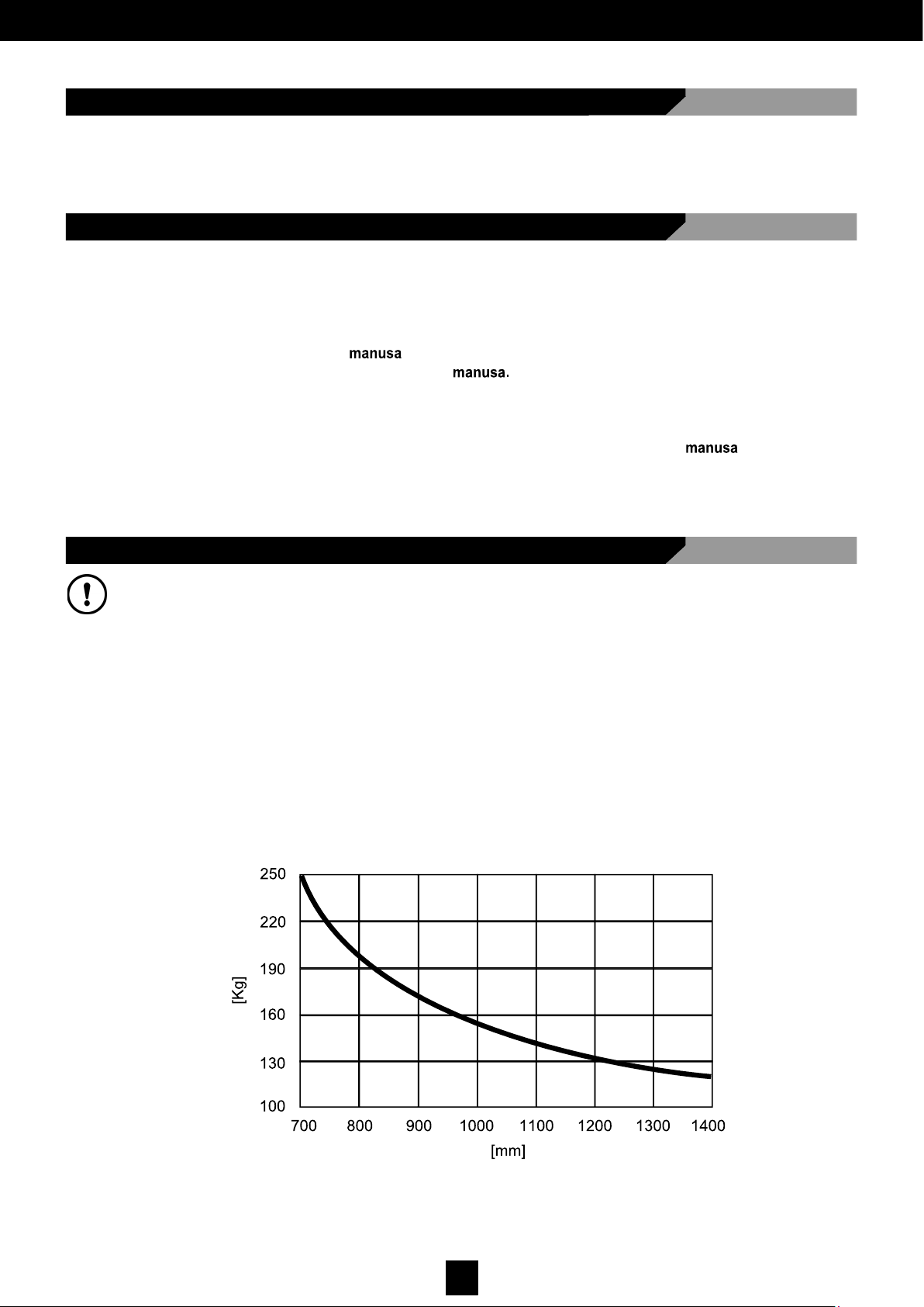
IMPORTANT: For the correct operation of the operator, the door must not exceed the weight or width indicated in
diagram Fig. 2.
Closing the door is performed by:
- Motor assisted spring (normal operation)
- Only the spring (operating without power)
In addition, each transmission is assigned a different maximum depth value of the frame, above which a correct installation
cannot be carried out. The operator is designed to function exclusively on swing doors in dry environments, and should be
installed inside buildings.
manusa is not responsible for damages arising from any use or placement different from that for which it was designed,
not for unauthorised modifications.
Fig. 2.
Leaf weight (kg)
Leaf width (mm)
Page 11

10
D00619EN - v0 SWING OPERATOR - INSTALLATION MANUAL
4 PRE-INSTALLATION
4.1 Training Requirements for Installation Technicians
Installing machines as well as any other intervention for maintenance, regulation adjustment, etc should be carried
out by qualified technical staff that meet the following requirements:
• Know how to use the maintenance and/or lifting equipment.
• Are able to correctly handle the loads.
• Know how to use the personal protective equipment.
• Know how to apply the Low Voltage Regulations instructions.
• Have technical knowledge of products.
• Know the reference and application standards for products and services.
4.2 Physical and Environmental Requirements
The VECTOR swing operator should be installed in places that meet the following requirements:
• Smooth, flat, level floor.
• Smooth, flat, level wall with sufficient load capacity. Capable of anchoring a suitable frame.
• An area free from shocks and vibrations.
Ambient temperature: -15 a +50ºC.
• Do not expose to direct sunlight.
• Do not expose to rain or excessive humidity.
Consideration of the location for the equipment should be carried out by technical personnel authorised by
During this process, the cable inlet location for the for the different units should be identified.
PRESSURE
In installations where the swing door is to be installed between two rooms with different pressure, it is recommended
that the door is planned for and installed such that the positive pressure always acts in the direction that the leaf
closes, thus helping to maintain the closed position.
Page 12
11
D00619EN - v0 SWING OPERATOR - INSTALLATION MANUAL
4.3 Electrical Pre-Installation Requirements
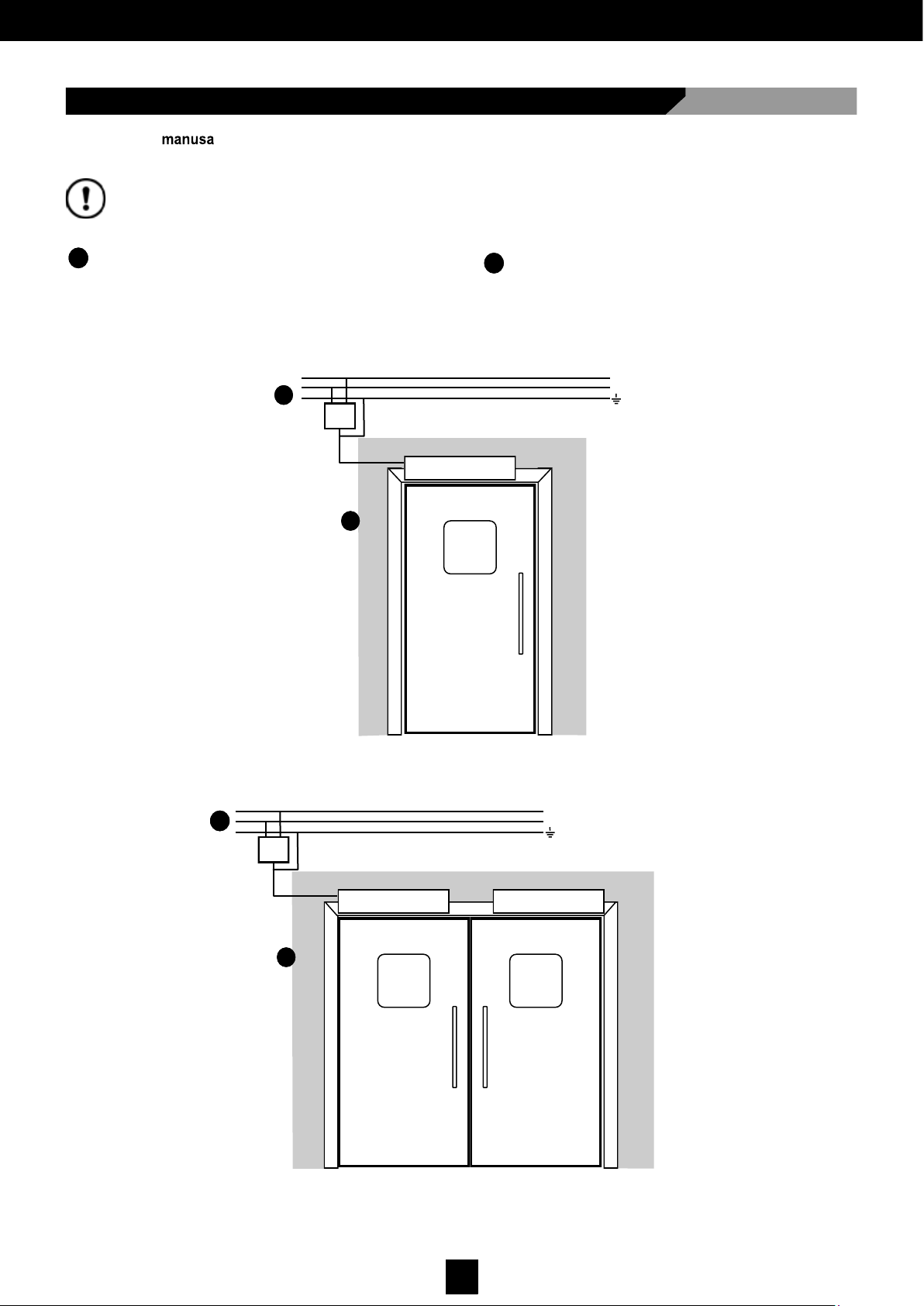
Assembling a automatic door requires an electrical pre-installation with a 6A double-pole magneto-thermal switch,
and it must comply with the cable sections specified below:
Current Input:
- 16mm corrugated tube.
- 3 cables 1.5mm2 section: phase + neutral + earth.
1
2
The diagram shows the standard wiring for the elements that the operator includes as standard.
4A
F
N
Monofásico / Single-phase / Monophasé = 220V - 240V ±6%
2
1
Radars:
- Cables supplied with the accessory.
1
6A
F
N
Monofásico / Single-phase / Monophasé = 220V - 240V ±6%
2
MASTER SLAVE
1
Page 13
12
D00619EN - v0 SWING OPERATOR - INSTALLATION MANUAL
5 INSTALLATION
5.1 Type of Arm that Can Be Installed
5.2 Installing the Operator
• RIGID ARM: (Used when the operator is installed on the same side that the door opens).
• STANDARD ARTICULATED ARM: The standard articulated arm can be mounted to PUSH. (It is used when the
operator is installed on the opposite side from where the door opens).
• LONG ARTICULATED ARM: The long articulated arm can be mounted to PUSH. (It is used when the operator is
installed on the opposite side from where the door opens, where the door jamb is particularly deep).
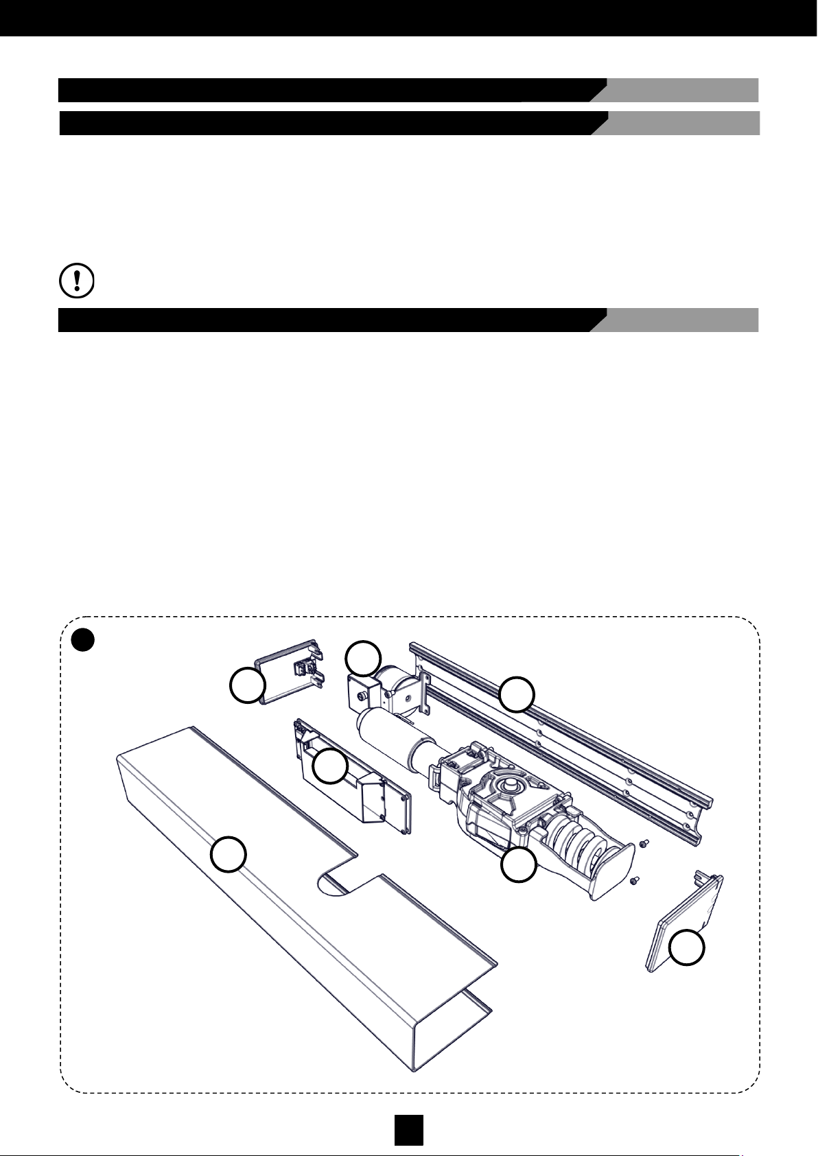
To attach the operator, follow the steps below (Fig. 3):
• Remove the main cover (B)
• Disconnect all connections (key-pad, switch, transformer, motor) on the electronic card ©, unscrew the 2 screws and
remove the card ©. The two screws remain in place between the circuit board and the lower base
• Unscrew and remove the 2 transformer fixing screws (G)
• Unscrew and remove the 4 gear motor group fixing screws (D)
• Remove the two end covers (E) and (F)
• Attach the main extruded profile (A) to the wall following the instructions in the following sections, depending on the type
of arm used
• Assemble all the components, with the exception of the end covers and the main cover, following the steps above in
reverse order.
When reassembling, to aid installation, tighten first the two lower gear motor group fixing screws, then support it on them,
tighten the other two, such that the gear motor shaft end is perpendicular to the upper profile of the leaf
5.2
A
WARNING: For a correct installation, consult the corresponding sections for ‘Installing the Arms’.
A
E
C
B
D
F
G
Fig. 3.
Page 14
13
D00619EN - v0 SWING OPERATOR - INSTALLATION MANUAL
5.3 Positioning Levels for the Fixing Holes
5.4 Extendable Rigid Arm Installation
Make suitable holes for the type of fixing screw to be used, only after checking the ‘Positioning Levels’ indicated in the
sections corresponding to the type of arm used. In the case of a double operator, prepare the connections (cable
routes) between the two individual operators.
The rigid arm is used when the operator is installed on the same side as the door opens.
WARNING: To place the operator correctly, always use as the main reference the axis of the leaf hinges and the drive
shaft of the gear motor, as shown in Fig. 6 (LEFT-opening leaf) and Fig. 7 (RIGHT-opening leaf).
WARNING: The final tightening of the screws should be performed only after ensuring that the operator has been
placed vertically, guaranteeing that the hinges and the gear motor drive shaft are perfectly parallel. For this to happen,
after installing the rigid arm and the corresponding guide, ensure that the arm pin is not applying any force to the
cylindrical runner during the manoeuvre phase. An error in the positioning of the operator will cause the rigid arm pin to
oscillate with respect to the cylindrical runner, increasing the admissible tolerance and consequently causing a part of
the operator to deteriorate.
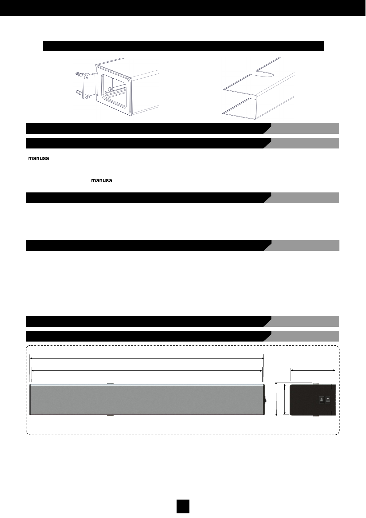
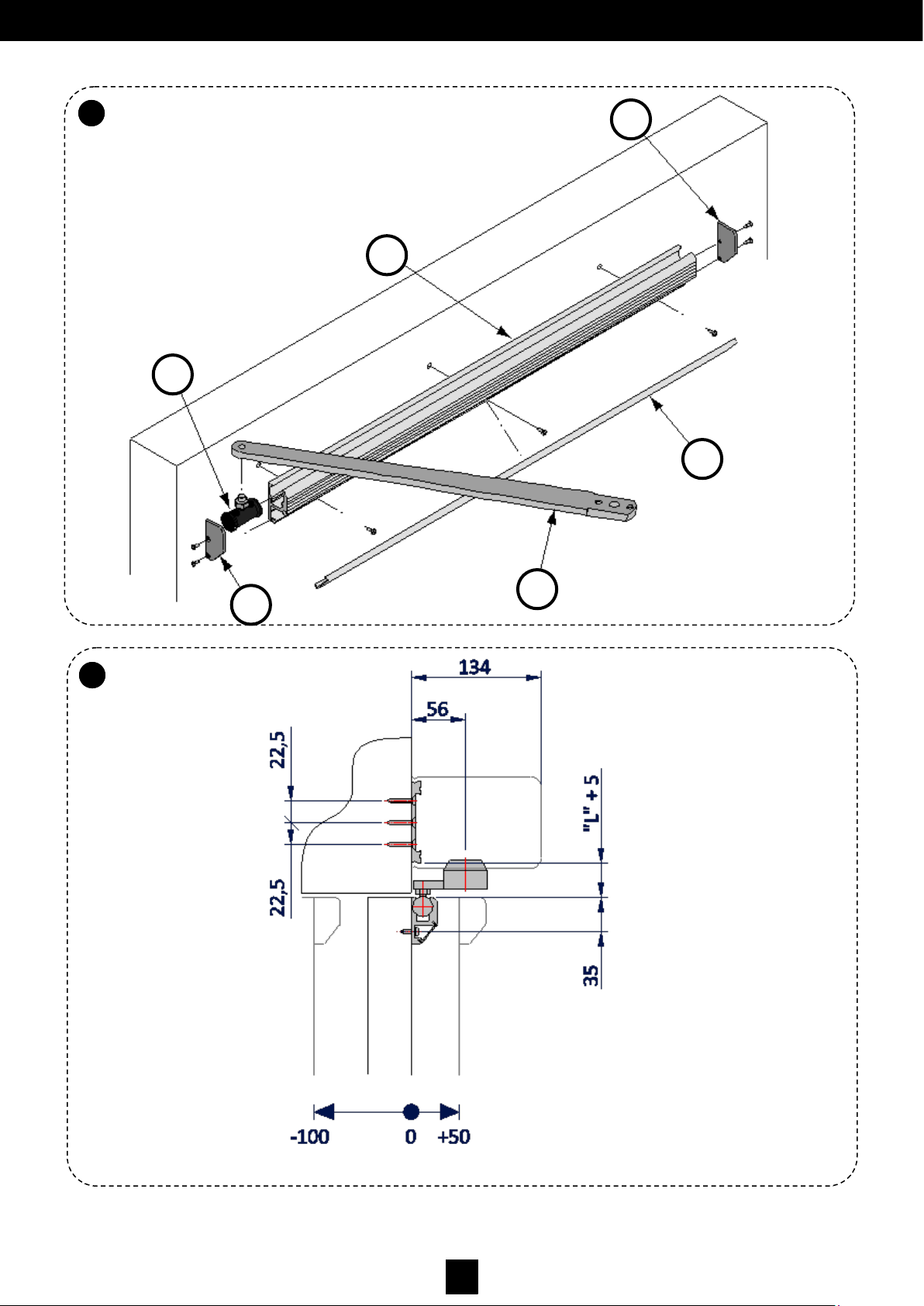
• Remove the cover (Fig. 4 Part A) from the main guide profile (Fig. 4 part B) to access the mounting compartment.
• Place the main guide profile (Fig. 4 part B) horizontally, following the fixing positioning levels indicated in
figures 5, 6 and 7.
• Make at least 4 holes coinciding with the ‘V’ mark on the guide profile, and attach it (Fig. 4 part B) to the frame using the
corresponding screws.
• Place the runner (Fig. 4 part C) in the guide (Fig. 4 part B).
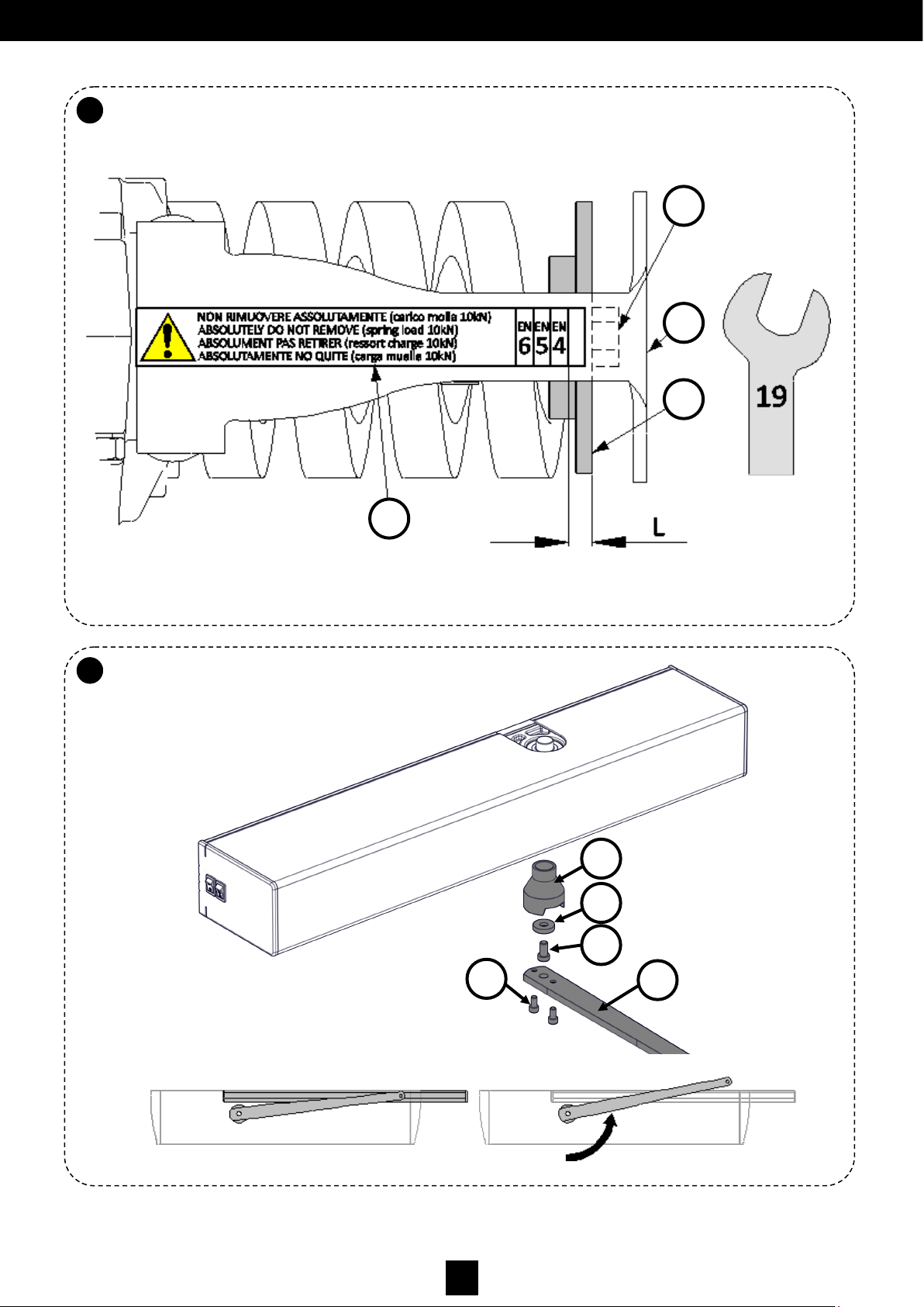
• Tighten the nut (Fig. 8 part A) so that the spring is previously loaded until the plate ends (Fig. 8 part B) coincide with the
line that indicates the EN4 range start point (level L=0).
• With the door closed, find the position to introduce the arm (Fig. 9 part A) so that the ends of the arm (Fig. 4 part F)
coincide with the axis of the runner pin (Fig. 4 part C).
• Remove the arm, take out the arm connection and turn it (Fig. 9 part A) 1 or 2 teeth towards the closing part of the leaf
(Fig.10). Then re-insert the output axis.
• Insert the washer (Fig. 9 part B) and tighten the screw (Fig. 9 part C).
• Unscrew the spring tension screw slightly (Fig. 8 part A).
• Insert the arm (Fig. 9 part D) into the arm connection groove, and tighten the two screws (Fig. 9 part E).
• Open the door slightly and turn the rigid arm until the runner axis (Fig. 4 part. C) coincides with the end of the rigid arm
where the arm pin is attached.
• Screw the threaded end of the pin (Fig. 4 part C) to the rigid arm (Fig. 4 part F).
• Close the guide cover (Fig. 4 Part A) .
• Close the guide right (Fig. 4 part E) and left (Fig. 4 part D) end covers with the corresponding screws.
• Adjust the spring [see section ‘Spring Adjustment’].
5.4.1 Rigid Arm and Guide Installation
Page 15
14
D00619EN - v0 SWING OPERATOR - INSTALLATION MANUAL
5.4
A
5.4
B
Fig. 4.
Fig. 5.
D
A
B
E
C
F
Page 16

15
D00619EN - v0 SWING OPERATOR - INSTALLATION MANUAL
5.4
C
5.4
D
Fig. 6.
Fig. 7.
A
A
A
A
Page 17
16
D00619EN - v0 SWING OPERATOR - INSTALLATION MANUAL
5.4
E
5.4
F
Fig. 8.
Fig. 10.
A
E
C
B
D
Fig. 9.
A
B
C
D
Page 18
17
D00619EN - v0 SWING OPERATOR - INSTALLATION MANUAL
5.4
G
• Place the washer (Fig. 9 part B) and the screw (Fig. 9 part C) on the connection point with the arm (Fig. 9 part A).
• Place the first part of the articulated arm (Fig. 15 part D) in the arm joining cavity as shown in Fig. 9, and tighten the
screws (Fig. 9 part. E).
• Unscrew the three M8 x 16 screws (Fig. 16 part B) so that the part of the arm that fixes to the leaf is separated.
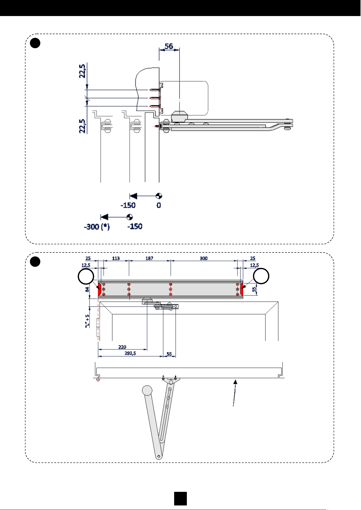
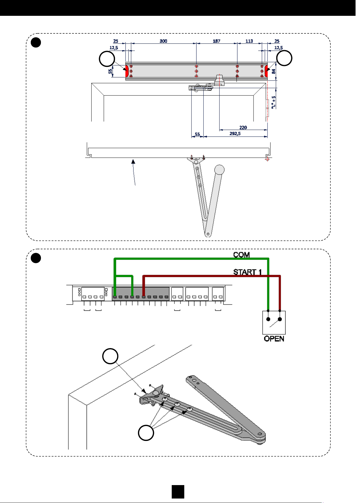
• Make holes in the door as indicated in figures 12 and 13.
• Affix the leaf-joining part of the articulated arm (Fig. 16 part. A) to the door leaf using the appropriate screws.
Before tightening the arm connection to the operator axis, check that the distance between the guide and the upper
side of the arm is about 17mm.
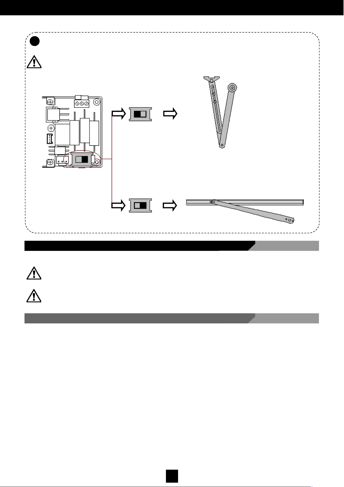
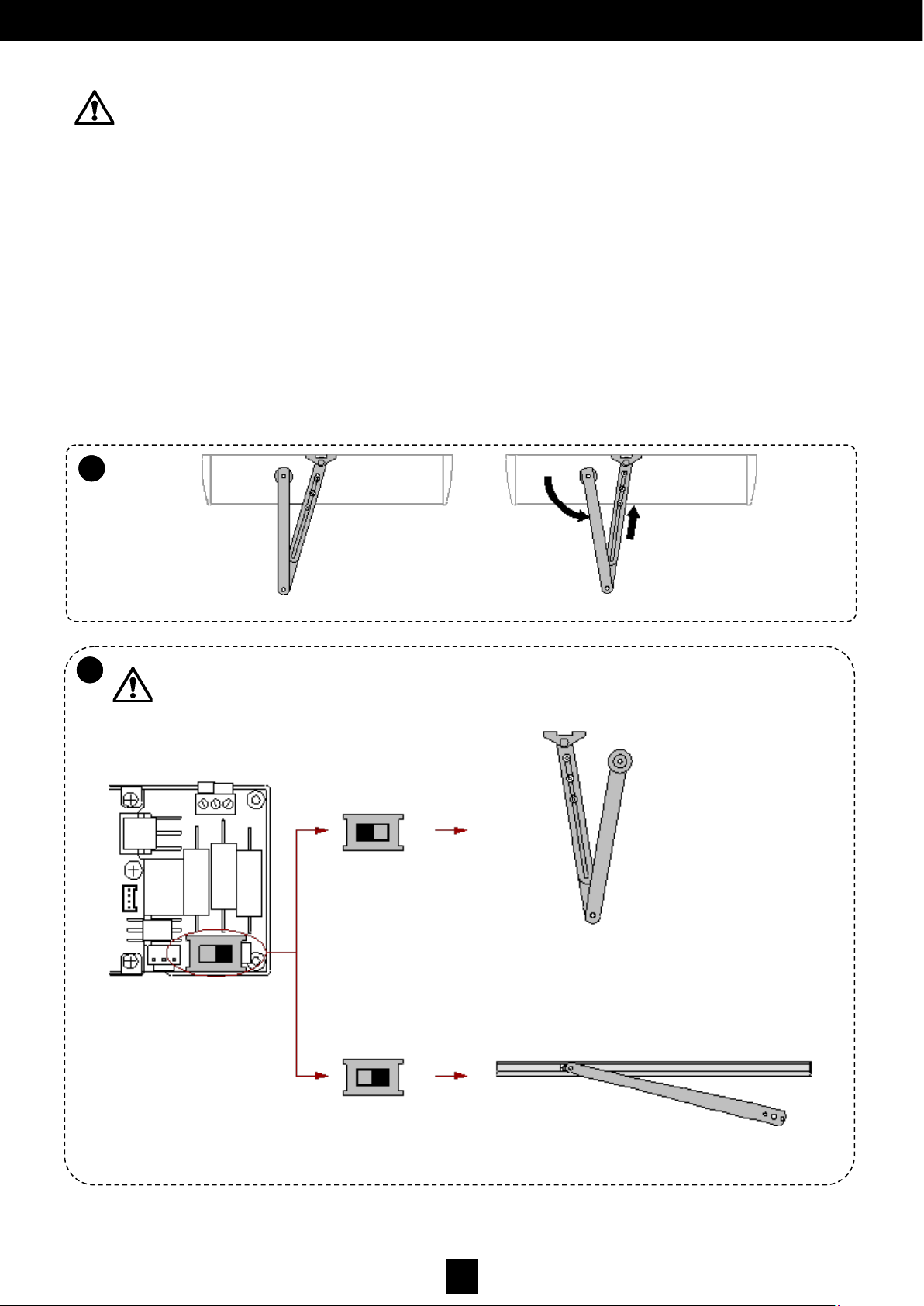
WARNING: After installing the rigid arm and the guide, ALWAYS check that the Switch position is to the right,
as shown in Fig. 11.
Fig. 11.
5.5.1 Attaching the Arm to the Leaf
The pushing articulated arm is used when the operator is installed on the opposite side from where the door opens.
WARNING: To correctly place it, always use as main reference the axis of the leaf hinges and the motor drive shaft,
as shown in Fig. 12, Fig. 13 (LEFT-opening leaf) and Fig. 14 (RIGHT-opening leaf).
WARNING: The final tightening of the screws should be performed only after ensuring that the position of the operator
and the articulated arm guarantee that it can easily rotate within the door frame.
CARACTERÍSTICAS MECÁNICAS
5.5 Installing the Pushing Articulated Arm
Page 19
18
D00619EN - v0 SWING OPERATOR - INSTALLATION MANUAL
5.5
A
5.5
B
Fig. 12.
Fig. 13.
A
A
Page 20
19
D00619EN - v0 SWING OPERATOR - INSTALLATION MANUAL
5.5
C
5.5
D
Fig. 14.
Fig. 15.
Fig. 16.
A
A
A
B
LOCK
GND
DATA
PWF
RST
OUT
15VDC
COM
AUX- IN2
AUX- IN1
START 2
START 1
COM
KEY
SAFE - CLOSE
SAFE - OPEN
COM
AUX– OUT2
AUX– OUT1
A
B
A
B
+
-
-
+
Page 21
20
D00619EN - v0 SWING OPERATOR - INSTALLATION MANUAL
5.5
F
WARNING: Attach the door’s leaf-joining point to the arm correctly, using reinforcements where necessary.
• Turn the nut (Fig. 8 part A) to preload the spring, until the plate ends (Fig. 8 part. B) coincide with the line indicating the
start point of the EN4 range (level L=0).
• Place the arm connection (Fig. 9 part A) on the operator output axis, so that the first part of the arm is perpendicular to
the operator mounting surface (Fig. 17).
• Tighten the screw (Fig. 9 part C) so that the arm connection remains anchored to the operator output axis.
• Screw in the three M8 x 16 hexagon button-head screws (Fig. 16 part B) without tightening so that the parts that make
up the articulated arm are joined together.
• With the leaf close, turn the part of the arm where the connection is to slightly compress the spring (see fig. 17).
• Fix the adjustment by firmly tightening the three M8 x 16 fixing screws (Fig. 16 part. B).
• Adjust the spring [see section ‘Spring Adjustment’].
WARNING: After installing the rigid arm and the guide, ALWAYS check that the Switch position is to the
left, as in Fig. 11.
Fig. 17.
Fig. 11.
5.5
E
Page 22
21
D00619EN - v0 SWING OPERATOR - INSTALLATION MANUAL
5.6 Spring Adjustment
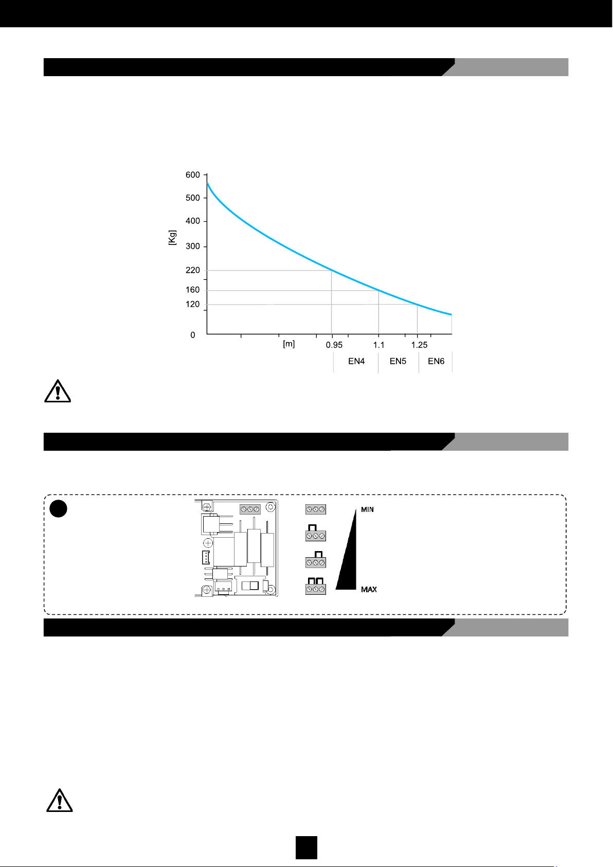
The strength of the spring should be adjusted according to the leaf width, and taking into account standard EN 1154 within
the range EN 4 to EN 6.
The adjustment range can be seen in the graph curve in Fig. 18, depending on the weight and width of the swing leaf,
and regardless of the type of arm installed. When adjusting the spring, take into account loads due to wind, excessive
pressure and other environmental conditions that tend to open a door on their own. Adjust the strength of the spring
tightening the screw (Fig. 8, Part A) such that it tenses the spring until the plate ends (Fig. 8 part B) are in the category
corresponding to the installation type (identified EN class).
Fig. 18.
WARNING: Taking into account that the spring is a component that accumulates a great deal of energy when fully
compressed, it is imperative to replace the spring and all components that operate with it exclusively with ORIGINAL
spare parts. It is convenient that a qualified technician performs scheduled maintenance tasks. For maintenance
information, refer to chapter 8 of this manual.
5.7 Selecting Breaking Level without Power
Adjust the breaking level such that it suits the closing speed and dimensions/weight of the leaf (Fig. 16). Check operation by
opening the door manually and closing it with the spring when there is no power.
Fig. 19.
5.8 Testing Operations
Before making the electrical connection, clean any traces of dust or debris and test the following items:
• The operator is correctly mounted on the wall.
• All the screws are tight.
• Check the wiring and ensure there are no wires near moving parts.
• The arm is correctly attached to the leaf.
• The heads are correctly placed and fixed at the base.
WARNING: Check the spring protection bracket (Fig. 8, part C) and ensure that the anti-tampering seal sticker has not
been removed (Fig. 8, part D).
5.7
A
Page 23
22
D00619EN - v0 SWING OPERATOR - INSTALLATION MANUAL
5.9
B
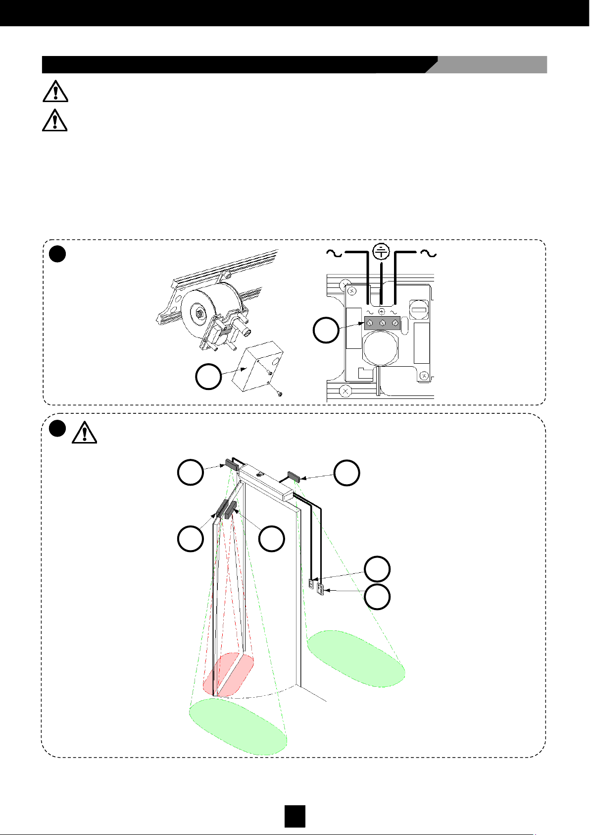
5.9 Connecting to the Power Supply
• Route the power cable to the interior of the operator without damaging it on any metallic edges.
• Open the cover (Fig.20 Part A).
• Connect the mains power supply and earth outlet cable on the terminal plates as shown in (Fig. 20 Part B).
• Replace the cover (Fig. 20 Part A).
WARNING: Do not invert the power supply and earth cables.
It has to be possible to section the power from the mains junction box using a two-pole switch
(see Fig. 21 E) with a 3mm minimum contact opening (not supplied).
WARNING: All the connection operations on the card terminal plates or the peripheral devices should be made with
the power disconnected to avoid irreversible electrical damage.
WARNING: Before continuing further operations, ensure that it is disconnected from the mains. Before connecting the
unit to the power supply, carry out the controls detailed the section ‘Commissioning’.
Fig. 20.
Fig. 21.
5.9
A
A
B
A B
C
D
E
F
Page 24
23
D00619EN - v0 SWING OPERATOR - INSTALLATION MANUAL
5.10
A
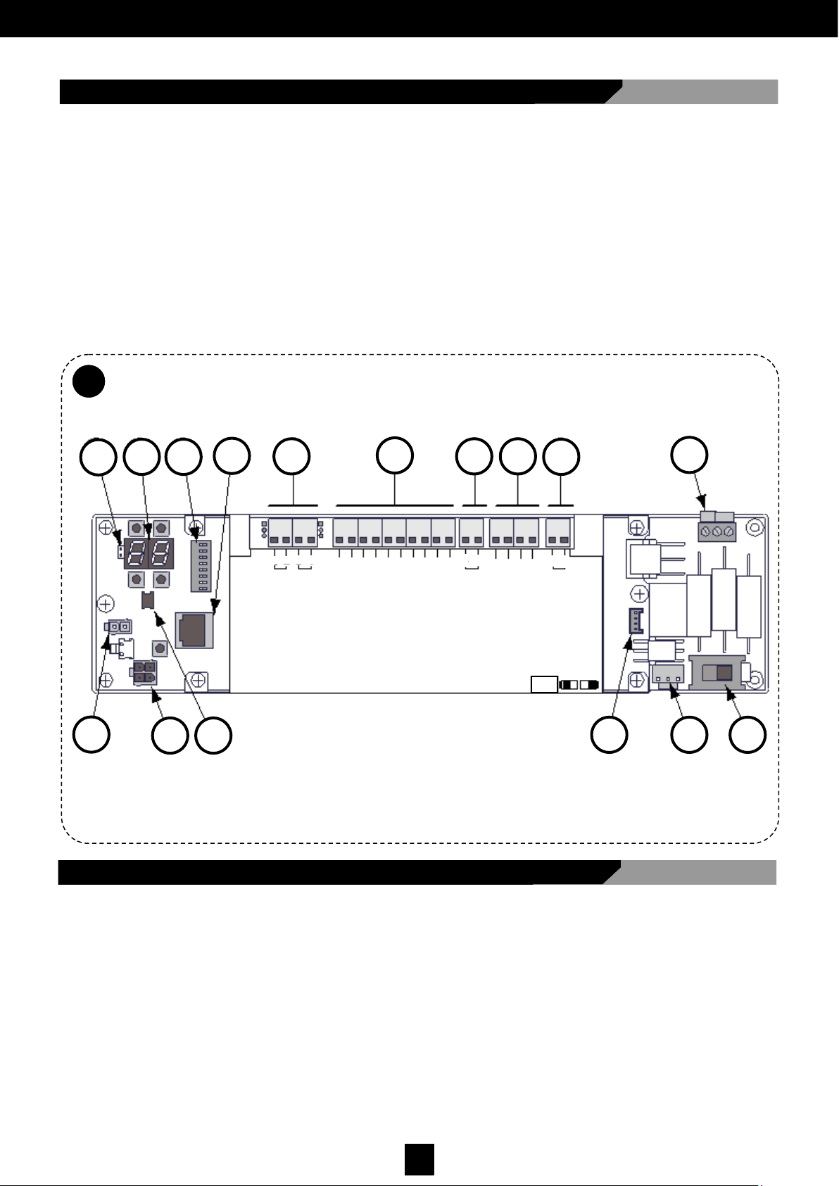
5.10 VECTOR Electronic Card
Fig. 22 shows the main components of the electronic card:
I - Controls/inputs connectors
J - Power supply for the sensors/accessories
K - Multi-logical program switch connector
L - Electronic lock connector
M - Key-pad connector
N - Motor connector
O - Braking level selector connector
P - Arm type program switch
A - Jumper to display viewing
B - Display and buttons
C - Dip switches
D - PC connector
E - Transformer connector
F - ON-OFF switch connector
G - Logic setting selection switch connector
H - Auxiliary output connections
Fig. 22
5.11 Electronic Connections
• Logic settings switch connector [H]
• ON-OFF switch connector [G]
• Transformer connector [E]
• Motor connector [O]
• Key-pad connector [N]
Connect to the electronic card (Fig. 22):
A
O D
G F
E
C
H
I J K
B L
M
N P
LOCK
GND
DATA
PWF
RST
OUT
15VDC
COM
AUX- IN2
AUX- IN1
START 2 START 1
COM
KEY
SAFE - CLOSE
SAFE - OPEN
COM
AUX– OUT2
AUX– OUT1
A
B
A
B
+
-
-
+
RIGID ARM
ARTICULATED ARM
MANUAL
I O II
TWO RADARS
STOP OPEN
Page 25
24
D00619EN - v0 SWING OPERATOR - INSTALLATION MANUAL
5.12 Arm-Type Selection
Rigid arm (Left or right-opening leaf)
→ Configure the right program switch as shown in Fig. 11.
Articulated arm (Left and right-opening leaf)
→ Configure the left program switch as shown in Fig. 11.
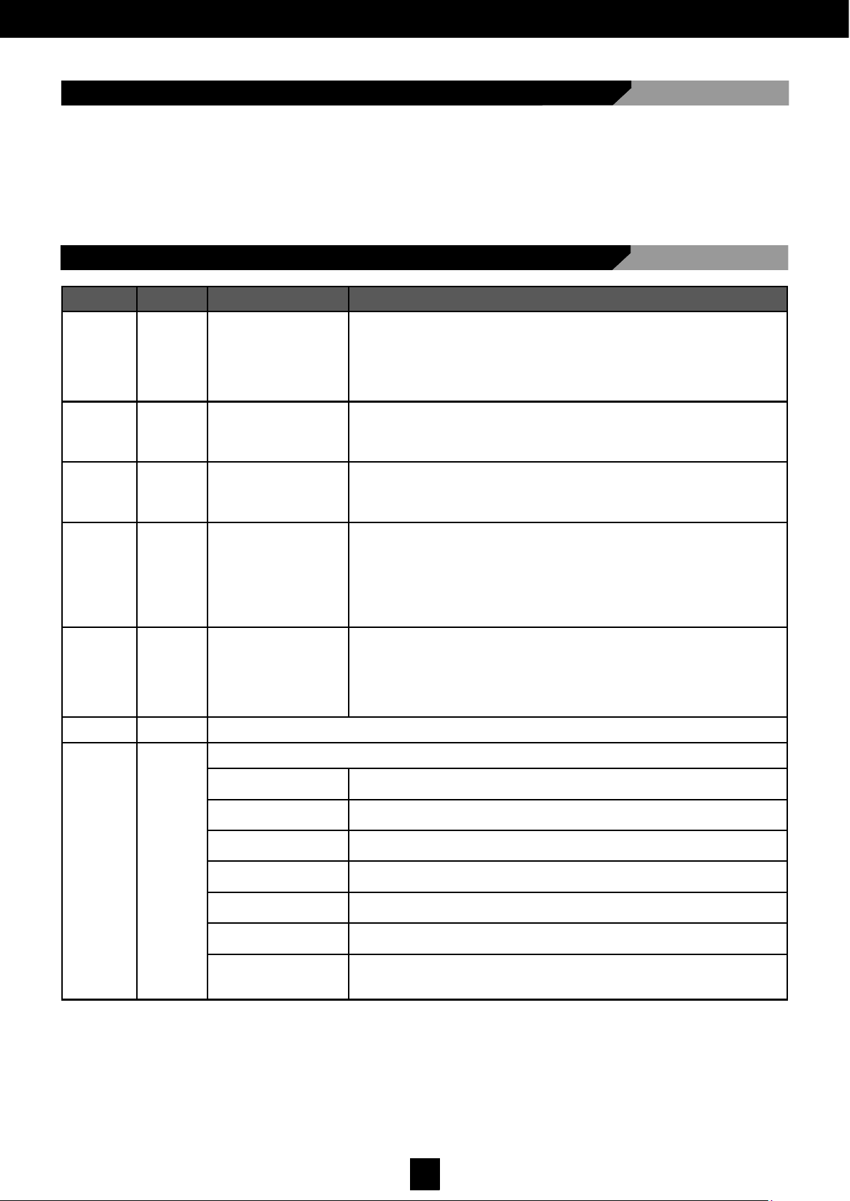
5.13 Connecting the Controls/Inputs
SIGNAL DEFAULT
*
DESCRIPTION FUNCTION
KEY NC
Lock signal. Closing
devices, such as the
electronic key, the
key program switch,
the transponder, etc.,
may be connected.
If the signal starts, the central unit controls the full leaf closing (from any
position). Until this signal is no longer received, the door will remain
closed and will not detect any external peripheral devices (including the
multi-logic program switches).
The signal should be shorted with COM if there are no devices connected.
START 1 NO
Opening signal. Devices can be connected for leaf opening
control.
The end of this signal causes the leaves to open. This signal is controlled
only with 2 radars logic setting.
START 2 NO
Opening signal. Devices can be connected for leaf opening
control.
The end of this signal causes the leaves to open. This signal is controlled
both with 2 radars logic setting and 1 radar logic setting.
SAFE
OPEN
NC
Opening safety signal: other protective
sensors can be connected for additional
safety during the
opening phases of
the leaves.
If the door is in the opening phase and the contact is open, the central unit
will order the manoeuvre to immediately stop. Opening will continue only
after this signal has been deactivated.
The signal should be shorted with COM if there are no devices connected.
SAFE
CLOSE
NC
Closing safety signal:
other protective sen-
sors can be connected for additional safety during the closing
phases of the leaf.
If the door is in the closing phase and the contact is open, the central unit
will immediately order the reverse movement. Closing will start again only
once the contact is closed again.
The signal should be shorted with COM if there are no devices (internal or
external) connected.
COM Common in electrical signals.
AUX IN 1
AUX IN 2
NO
Signal that, depending on the settings, may have the following configurations:
0 - Disabled persons
opening
Opening control for disabled persons. LOW ENERGY open and close with
a minimum 5 second pause.
1 - Emergency
opening
It controls door opening regardless of the existing logic settings, overriding
as priority even the KEY input.
2 - Door interlocking
with priority
It identifies the device used in the interlocking logic setting, with the door’s
as priority.
3 - Door interlocking
without priority
It identifies the device used in the interlocking logic setting, with the door’s
without priority
4 - Lock release
feedback
Control used to indicate that the lock is released. Connect the micro-
switch or the contact to detect the state of the released lock.
5 - Lock release
control
Control allowing the lock to be released manually, without controlling the
opening of the leaf.
6 - Individual control
with Double operation
mode
Signal that allows the device to be controlled as if it were individual when
it operates with a double leaf.
Page 26
25
D00619EN - v0 SWING OPERATOR - INSTALLATION MANUAL
5.14 Connector to Auxiliary Outputs
SIGNAL DEFAULT
*
DESCRIPTION FUNCTION
AUX OUT 1
AUX OUT 2
NA
A signal that, depending on its setting, can have the following configurations:
0 - Sensors supervision Signal to manage the supervised sensors.
1 - Interlocking
Allows the configuration of the device output, to enable
interlocking between the two operators.
2 - Open-door state Output that signals the open-door state.
3 - Closed-door state Output that signals the closed-door state.
4 - Malfunction Output that signals the operator malfunction state.
5 - Lock control repetition
This is a repetition of the signal that arrives from the lock
control.
AUX IN 1
AUX IN 2
NO
7 - Stand-by state
When the contact is closed, the door enters stand-by mode (unlocked
and deactivated). This logic setting only operates with the door in the
closed position.
8 - Activate again from
Stand-by
When the contact is closed, the door activates again after being in
stand-by.
9 - Step by Step function
For each impulse, the door, if closed, performs an opening manoeuvre, or if open, performs a closing manoeuvre.
10 - Fire alarm
VectorS: When the contact is closed, all commands are deactivated
and the door is closed by the spring
11 - Manual operation
VectorS: When the contact is closed, the door enters manual operation and the logic settings switch (Fig.1B) is excluded
12 - Door closed
VectorM: When the contact is closed, the door is placed in doorclosed mode and the logic settings switch (Fig.1B) is excluded
NO = Normally Open NC = Normally Closed
All inputs must refer to the common (COM); those indicated are preset configurations (default). These can be modified (see
section 5.17 Display Management)
NO =Normally Open NC =Normally Closed
All inputs must refer to the common (COM); those indicated are preset configurations (default). These can be modified (see
section 5.17 Display Management)
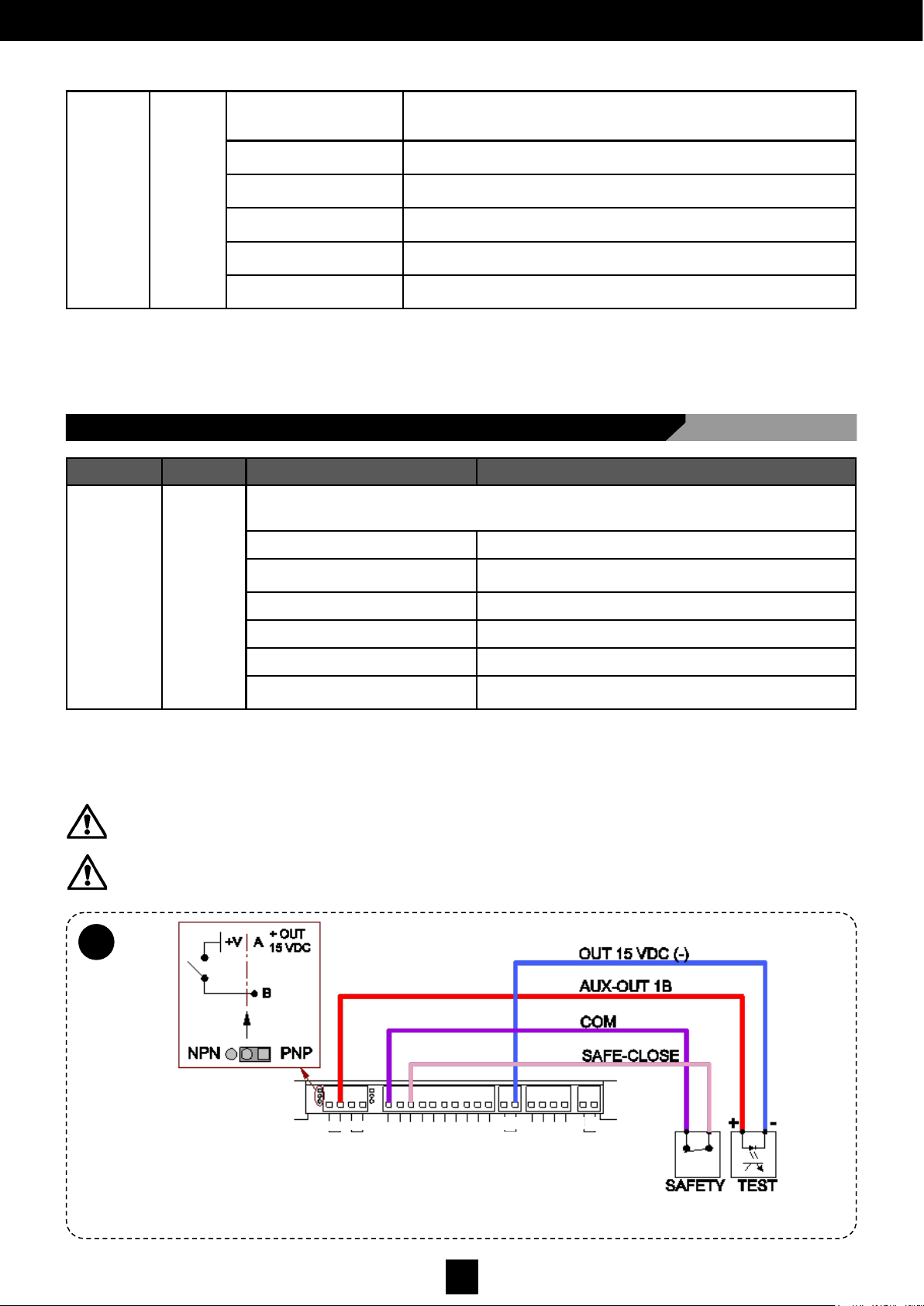
WARNING: To connect the auxiliary output signals, see the electrical connections shown in Fig. 23.
Maximum contact load: 24V - 100mA
WARNING: Overloading the card capacity may damage it.
Fig. 23.
5.14
A
LOCK
GND
DATA
PWF
RST
OUT
15VDC
COM
AUX- IN2
AUX- IN1
START 2
START 1
COM
KEY
SAFE - CLOSE
SAFE - OPEN
COM
AUX– OUT2
AUX– OUT1
A
B
A
B
+
-
-
+
Page 27
26
D00619EN - v0 SWING OPERATOR - INSTALLATION MANUAL
CARACTERÍSTICAS MECÁNICAS
5.15 Installing and Acquiring the Sensors
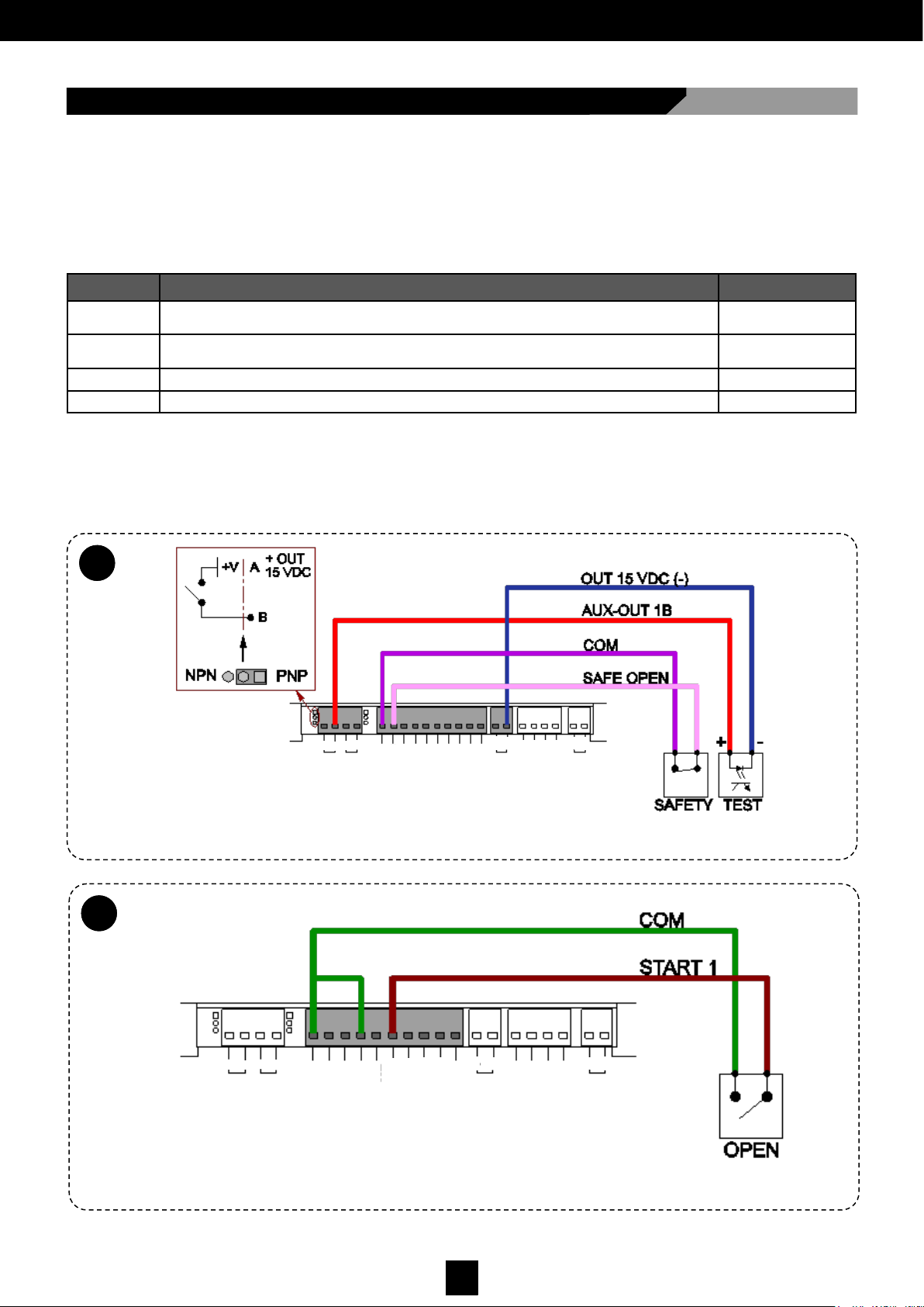
The operator is prepared to manage:
• Safety sensors (see Fig. 21 A and B): they are mounted on the leaf and control the nearby area to detect possible
obstacles, and stop movement or invert it to prevent blows, crushing or other sources of danger;
• Detection sensors (see Fig. 21 C and D): normally mounted on the wall, to detect when persons approach the door and
control the opening.
Connect the following sensors if they are present:
If, when the device is put into operation, the configuration of the supervised safety sensors has not yet been memorised, the
display will show error E6. Exit this state by activating the automatic supervised sensor acquisition procedure (parameter LS,
see section ‘Managing Operating Parameters of the Display’). During this procedure, the card waits until the sensors are
deactivated and checks the their supervision has been activated.
ID SENSOR DIAGRAM
17 = 0
30 = 1
Safety sensor supervised during closing (See Fig. 21 A) See Fig. 23
17 = 0
30 = 1
Safety sensor supervised during opening (See Fig. 21 B) See Fig. 24
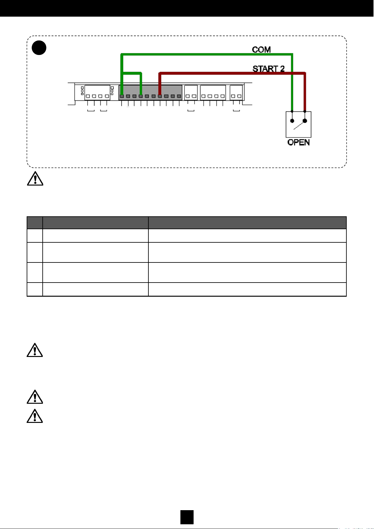
Detection sensor (radar) on entry (See Fig. 21 D) See Fig. 25
Detection sensor (radar) on exit (See Fig. 21 C) See Fig. 26
5.15
A
Fig. 24.
5.15
B
Fig. 25.
LOCK
GND
DATA
PWF
RST
OUT
15VDC
COM
AUX- IN2
AUX- IN1
START 2
START 1
COM
KEY
SAFE - CLOSE
SAFE - OPEN
COM
AUX– OUT2
AUX– OUT1
A
B
A
B
+
-
-
+
LOCK
GND
DATA
PWF
RST
OUT
15VDC
COM
AUX- IN2
AUX- IN1
START 2
START 1
COM
KEY
SAFE - CLOSE
SAFE - OPEN
COM
AUX– OUT2
AUX– OUT1
A
B
A
B
+
-
-
+
Page 28
27
D00619EN - v0 SWING OPERATOR - INSTALLATION MANUAL
5.15
C
Fig. 26.
WARNING: move away from the sensors so that they do not detect any obstacle and so that, when they deactivate,
they allow the acquisition process to finish. If they do not deactivate, the procedure will remain blocked and it can be
aborted by pressing the ESC key.
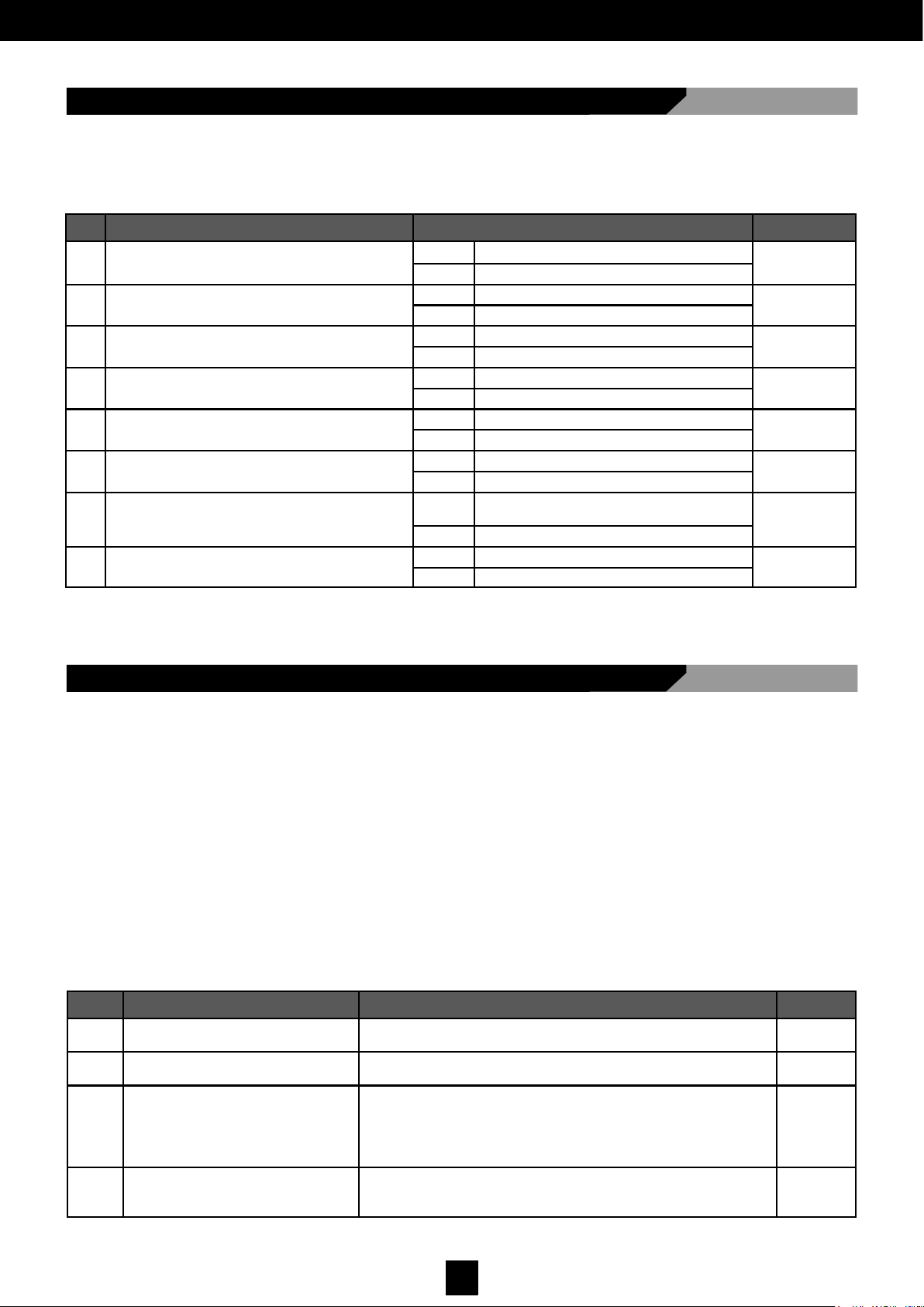
When the procedure is finished, the display will show one of four values depending on the configuration detected:
ID CONFIGURATION DESCRIPTION
S0 No supervised sensor detected
No sensors detected, or the sensors that may be connected are managed
as normal sensors, not as supervised sensors.
S1 Supervised sensor only during opening
The super vised sensor is managed only during opening.
During the closing phas e there is no sensor, or the sensor is manag ed as a normal sensor.
S2 Supervised sensor only during closing
The supervised sensor is managed only during closing. During the opening
phase there is no sensor, or the sensor is managed as a normal sensor.
S3
Supervised sensor both during opening
and closing
The supervised sensor is managed both during opening and closing.
The value will remain on the display until one of the following keys is pressed:
• ENT: To accept the detected configuration, ensuring that it corresponds effectively with the actual configuration of the
sensors connected to the operator.
• ESC: To reject the detected configuration and return to the E6 error state.
WARNING: Never accept the detected configuration if it does not coincide with the actual configuration of the
sensors connected to the operator. This may trigger highly hazardous situations or cause the operator to
malfunction.
WARNING: The automatic acquisition procedure of supervised sensors should be repeated every time the
configuration of the sensors connected to the operator is changed.
WARNING: In the case of the Double Vector (2 leaves) operator, THE AUTOMATIC ACQUISITION PROCEDURE
OF SUPERVISED SENSORS SHOULD BE CARRIED OUT ON BOTH ELECTRONIC CARDS (MASTER AND
SLAVE).
The acquisition procedure can be repeated at any time using the LS parameter (refer to section ‘Display Management’).
At start-up, the display shows the firmware version of the card, and then the configuration of the sensors in memory (S0; S1; S2;
S3), for 2 seconds.
If the supervision of a sensor malfunctions, the display will show the flashing value of this sensor (S1: opening safety device; S2: closing
safety device; S3: both). This signal will end once normal supervision has been re-established.
LOCK
GND
DATA
PWF
RST
OUT
15VDC
COM
AUX- IN2
AUX- IN1
START 2
START 1
COM
KEY
SAFE - CLOSE
SAFE - OPEN
COM
AUX– OUT2
AUX– OUT1
A
B
A
B
+
-
-
+
Page 29
28
D00619EN - v0 SWING OPERATOR - INSTALLATION MANUAL
CARACTERÍSTICAS MECÁNICAS
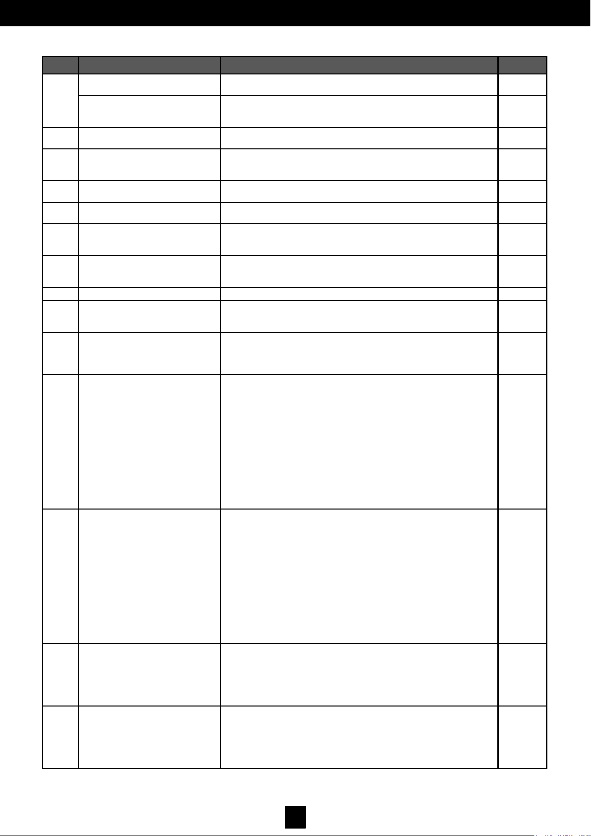
5.16 Dip-Switch Management
There is a dip-switch on the electronic card with 8 positions for configuring the functionality and ON-OFF type basic
operations. These settings are detected and memorised after a reset, and the possible dip-switch variations during operation
are not taken into account:
CARACTERÍSTICAS MECÁNICAS
5.17 Display Management
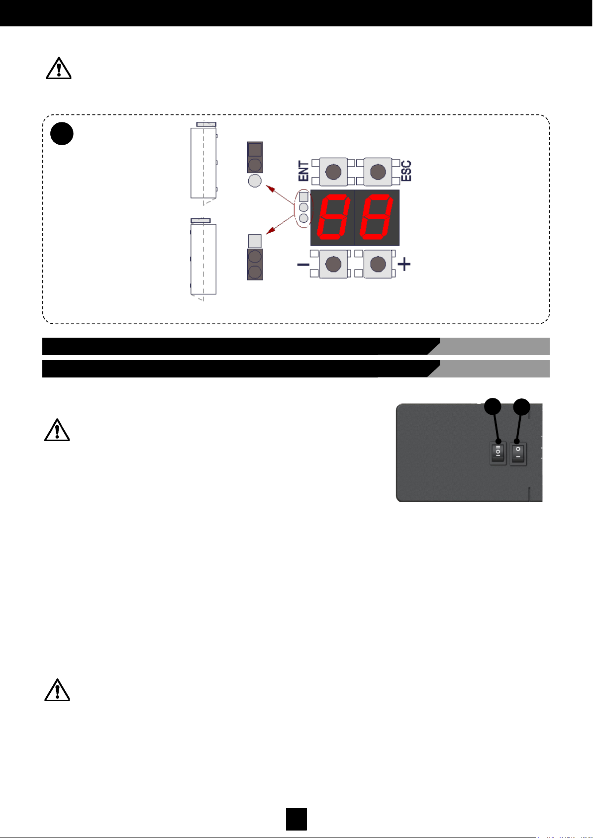
The two seven-segment displays shown in Fig. 27 and located on the electronic card with 4 buttons, control the main
parameters and the advanced options for managing the operator in various types of installation.
To correctly view the display, configure the jumper according to the side which the door will open, indicated in Fig. 27.
It can be programmed as follows:
1. Select the parameter which is to be modified with the [+] and [-] keys; during this phase the display shows the
indicated parameter. Pressing the [ESC] key exits the parameter selection phase, pressing [ENT] enters the
parameters view/edit phase.
2. The display flashes with the actual parameter value. The value can be changed using the [+] and [-] keys;
pressing the [ESC] key returns to the parameter selection phase without modifying the value, and pressing the
[ENT] key changes the value and returns to the parameter selection phase.
3. During the parameters selection/edit phase there is an active timeout; if no keys are pressed for a period of
10 seconds, it exits the programming phase.
4. In order to confirm the operational commands, it is necessary to press and hold the [ENT] key for 5 seconds,
after which the display returns to the parameter selection phase automatically.
ID DESCRIPTION SETTING DEFAULT
01 Opening speed
RANGE: 20°/s ÷ 70°/s
(Adjustable by amounts of 5°/s)
60
02 Closing speed
RANGE: 20°/s ÷ 40°/s
(Adjustable by amounts of 5°/s)
20
03 Normal stopping time
RANGE:
0 ÷ 60 seconds (Adjustable by amounts of1s);
62: 2 min
63: 3 min
64: 4 min
0
04
Disabled persons/Low Energy
stopping time
RANGE: 5 ÷ 60 seconds (Adjustable by amounts of1 second)
(Only active when aux is set to 0)
5
DIP PARAMETER VALUE DEFAULT
1 Arm type
OFF Articulated
OFF
ON Rigid
2
Mode
LOW ENERGY (LOW ENERGY LEVEL)
OFF Normal
OFF
ON Low Energy
3
Mode
PUSH&GO
OFF De-activated
OFF
ON Activated
4
Mode
KEY entry
OFF Bistable
OFF
ON Monostable
5 Actuator type
OFF VectorM
OFF (M)
ON (S)
ON VectorS (Spring)
6 Return close in non-manual mode
OFF Motorised return close
OFF
ON Return close by spring
7 Action after collision during closing by spring
OFF
Another motorised opening is not
performed
OFF
ON Another motorised opening is performed
8 Unused
OFF
OFF
ON
Page 30
29
D00619EN - v0 SWING OPERATOR - INSTALLATION MANUAL
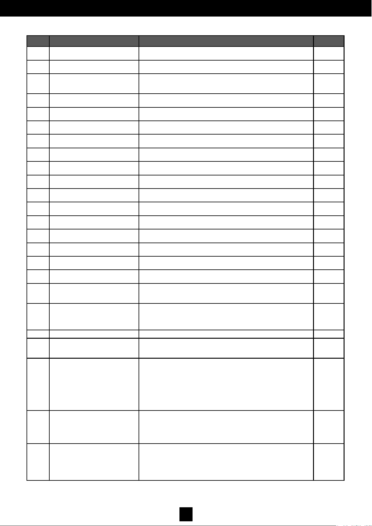
ID DESCRIPTION SETTINGS DEFAULT
05
Return closing speed with spring
(VECTORM)
RANGE: 1 ÷ 9
(1 = minimum speed, 9 = maximum speed)
5
Wind protection function with the
door closed (VECTORM)
RANGE: 0 ÷ 9
(0 = wind protection deactivated, 9 = maximum wind protection)
0
06 Crushing protection
RANGE: 1 ÷ 9 both opening and closing
(1 = most sensitive ; 9 = least sensitive)
5
07 Accelerations
RANGE: 5 ÷ 30
(Regulating steps of 1) Modifies both accelerations and
decelerations
30
08 Approach angle
RANGE: 10 ÷ 40
[modifies both values (close equal to half (1/2) of the opening)]
20
09 Electronic lock control voltage
0 = 12 VDC
1 = 24 VDC
0
10 Electronic lock types
0 = Not used
For electronic lock types that may be used, see section
‘Management of Electronic Locks’
0
11
Electronic lock impulse duration
or opening delay
RANGE: 0 ÷ 9
The time depends on the type of electronic lock:
see section ‘Management of Electronic Locks’
2
12 Electronic lock closing force RANGE: 0 (min.) ÷ 9 (max.) 5
13 Individual/double mode
0 = Individual
1 = Double Master
2 = Double Slave
0
14
Activation of the electronic lock
according to the selected logic
settings
0 = Deactivated
1 = One Radar
2 = Two Radars
3 = One Radar and Two Radars
3
15
Configuration of the auxiliary
input AUX-IN 1
0 = Disabled persons opening
1 = Emergency opening
2 = Door interlocking with priority
3 = Door interlocking without priority
4 = Lock release feedback
5 = Lock release control
6 = Individual control with operational mode with Double
7 = Puts the door in stand-by (if it is active)
8 = Resets door stand-by
9 = Step-step (1 impulse opens, 1 impulse closes)
10 = Fire alarm
11 = Manual operation
12 = Door closed
0
16
Configuration of the auxiliary
Input AUX-IN 2
0 = Disabled persons opening
1 = Emergency opening
2 = Door interlocking with priority
3 = Door interlocking without priority
4 = Lock release feedback
5 = Lock release control
6 = Individual control with operational mode with Double
7 = Puts the door in stand-by (if it is active)
8 = Resets door stand-by
9 = Step-step (1 impulse opens, 1 impulse closes)
10 = Fire alarm
11 = Manual operation
12 = Door closed
1
17
Configuration of the
auxiliary output AUX-OUT 1
0 = Monitoring the sensors
1 = Interlocking
2 = Open-door state
3 = Closed-door state
4 = Malfunction
5 = Lock control repetition
0
18
Configuration of the
auxiliary output AUX-OUT 2
0 = Monitoring the sensors
1 = Interlocking
2 = Open-door state
3 = Closed-door state
4 = Malfunction
5 = Lock control repetition
1
Page 31
30
D00619EN - v0 SWING OPERATOR - INSTALLATION MANUAL
ID DESCRIPTION SETTING DEFAULT
19 MultiMaster address
0 = Multimaster not managed
1÷ 15 = Unique address for MultiMaster connections
0
20 Exclusion of opening safety
Angle of safety sensor exclusion during opening
RANGE: 0 ÷ 40% of the entire course
0
21 Double opening delay
RANGE: 0 ÷ 100
Opening delay in 100ms units
(if 0 they are synchronised)
0
22 Double closing delay
RANGE: 0 ÷ 100 Closing delay in 100ms units
(if 0 they are synchronised)
0
23 Input polarity SAFE OPEN
0 = NA (Normally Open)
1 = NC (Normally Closed)
1
24 Input polarity SAFE CLOSE
0 = NA (Normally Open)
1 = NC (Normally Closed)
1
25 Input polarity KEY
0 = NA (Normally Open)
1 = NC (Normally Closed)
1
26 Input polarity START 1
0 = NA (Normally Open)
1 = NC (Normally Closed)
0
27 Input polarity START 2
0 = NA (Normally Open)
1 = NC (Normally Closed)
0
28 Input polarity AUX IN1
0 = NA (Normally Open)
1 = NC (Normally Closed)
0
29 Input polarity AUX IN2
0 = NA (Normally Open)
1 = NC (Normally Closed)
0
30 Output polarity AUX OUT 1
0 = NA (Normally Open)
1 = NC (Normally Closed)
0
31 Output polarity AUX OUT 2
0 = NA (Normally Open)
1 = NC (Normally Closed)
0
32
Level of force during LP procedure
RANGE: 5 ÷ 60 (0 = minimum force ÷ 9 = maximum force) 5
33
Percentage level of opening
angle reduction
RANGE: 0÷50% 0
34 Leaf installation
0 = mounted on lintel
1 = mounted on the leaf (reverse)
0
35
Opening speed for disabled persons
0 = Low Energy
1 = Speed as indicated in parameters 1 and 2
0
36 Battery operation (only vectorS)
0 = standard (spring only)
1 = continuous operation
2 = panic breakout
0w
37
Configuration of the START 2
input
0 = Operates as indicated on page 13
1 = Disabled persons opening: activate with switch B-fig.1- given in
logic settings 1
2 = Disabled persons opening: activate in all logic settings
0
ST Stop movement
TS Test
0 = normal operation
1 = normal cycle
2 = quick cycle
0
LS
Learning sensor (Procedure for
automatically acquiring the supervised sensors).
1 - Select LS using keys [+] and [-]
2 - Press [ENT] to begin the procedure
3 - The display shows a value (SO; S1; S2; S3) that corresponds to
the detected configuration (sea section ‘INSTALLING AND AC-
QUIRING THE SENSORS’)
4 - press ENT to accept the detected configuration; ensure that it effectively
corresponds to the actual configuration of the sensors connected to the
operator, or ESC to reject the detected configuration.
Sd
Default configuration of all the
parameters and points reset
1 - Select Sd using keys [+] and [-].
2 - Press [ENT].
3 - When the display shows [--], press [ENT] again for 5 seconds
to confirm.
4 - When the display stops showing [--], release the [ENT] key.
Lp Acquiring the leaf parameters
1 - Select Lp using keys [+] and [-].
2 - Press [ENT].
3 - When the display shows [--], press [ENT] again for 5 seconds
to confirm.
4 - When the display stops showing [--], release the [ENT] key.
Page 32
31
D00619EN - v0 SWING OPERATOR - INSTALLATION MANUAL
WARNING: During the parameters modification phase, all motor movements will be disabled.
When not using programming, the [ENT] key is an opening control (only for logic settings One Radar or two Radars).
6. COMMISSIONING
5.17
A
Fig. 27.
• Turn switch (A) OFF.
A B
• Connect the operator power supply to the 230v mains supply.
• Turn switch (A) to ON.
• Check that the display comes on and that E6 is shown: if necessary, configure the jumper to see the display correctly
(See Fig. 27);
• 5. Select LS with the [+] and [-] keys and press [ENT]; when [--] is shown, press [ENT] again for 5 seconds to confirm;
when [--] is no longer displayed, release the [ENT] key: the process for acquiring the supervised sensors will begin (see
section ‘Installing and Acquiring Supervised Sensors’ to finalise the procedure).
• 6. If an electronic lock is installed, configure the parameters 10/11/12/14 (see sections ‘Display Management’ and/or
‘Electronic Lock Management’)
• 7. Using the [+] or [-] key, select LP and press [ENT]; when [--] is shown, press [ENT] again for 5 seconds to confirm the
command; when [--] is no longer displayed, release the [ENT] key. The door will open and the parameters acquisition
cycle will begin.
WARNING: Check again whether DipSwitch has been configured correctly,
especially No. 1 and No. 5. Check again whether the contacts and KEY,
SAFE CLOSE and SAFE OPEN are correctly connected or, if not to be used,
they are connected to COM.
WARNING: During the door opening process, block the leaf’s opening degree to the desired position to set the end of
its run. Immediately after, the door will close completely and the display will flash CL. Once the door reaches the
completely closed position and CL is no longer flashing, you may check that the operation is working by pressing the
[ENT] key: the door will open and close normally. The opening angle during normal operation is reduced with respect
to that detected during the acquisition of the targets, allowing it to operate without completing its mechanical run.
The percentage reduction is defined by parameter No. 33 each time that it is switched on again (or the RESET
manoeuvre is executed); the device will go to the completely closed position. Following that, the first manoeuvre will
be carried out at a reduced speed.
6.1 Start-Up
Page 33
32
D00619EN - v0 SWING OPERATOR - INSTALLATION MANUAL
CARACTERÍSTICAS MECÁNICAS
6.2 Management and Use
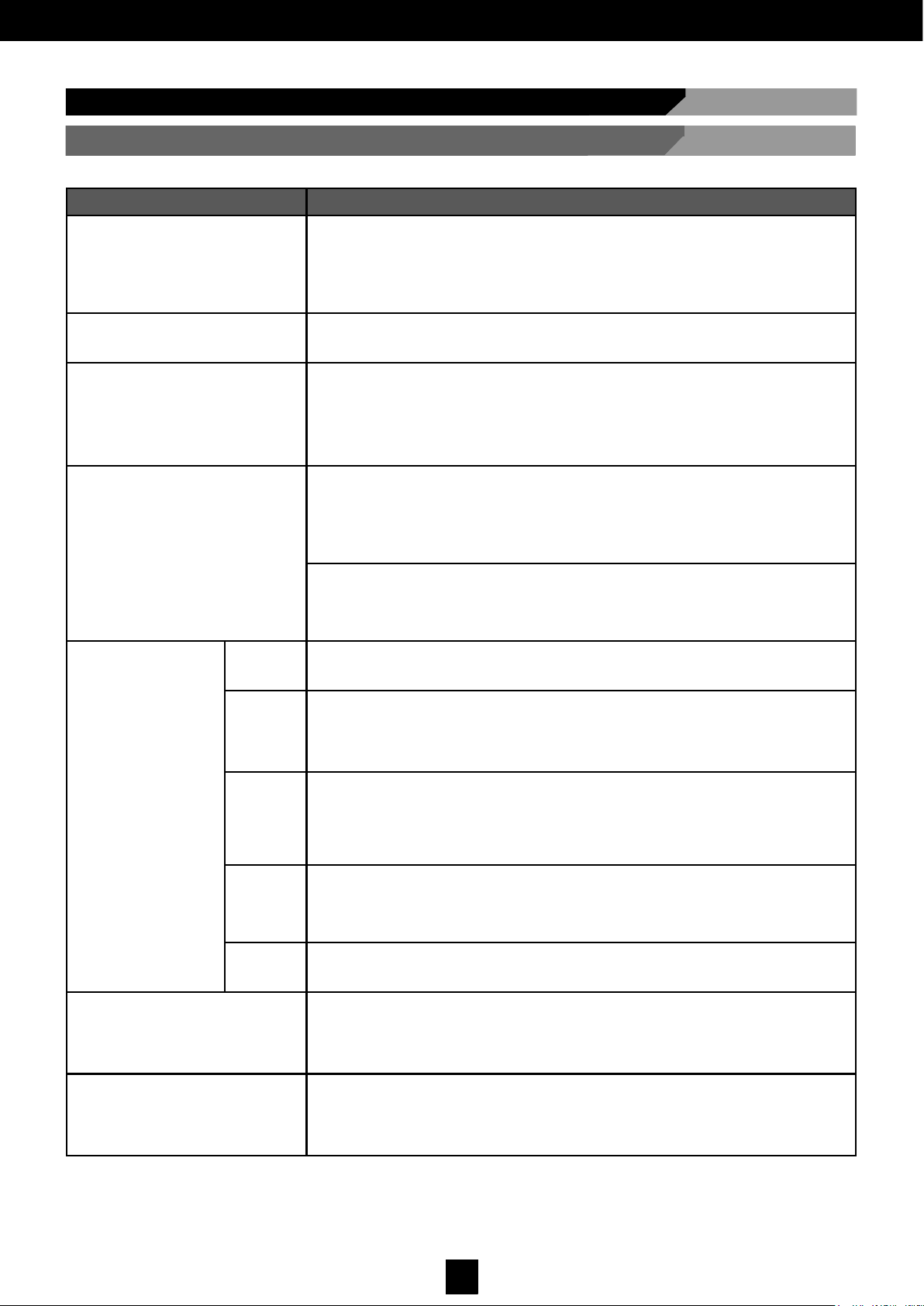
6.2.1 Operational Logic Settings
LOGIC SETTING DESCRIPTION
LOW-ENERGY
In all operating modes (excluding Stop Closed) a motorised reduced-speed
opening (velocity Low Energy) and an augmented stop period (disabled persons stop time) can be achieved using the disabled persons opening controls (in the configuration input [AUX IN 1 configuring the parameter 15=0,
section ‘Management of the Operational Parameters-display’]). Closing will
be carried out by the spring with obstacle control.
PUSH & GO:
Manually moving the stationary leaf when in the closed position will automatically create an opening and closing manoeuvre. To configure this logic setting it is necessary
to set DIP 3 = ON.
SAFE CLOSE
If the safety sensor mounted on the closing leaf and which is connected to the electronic card (in Safe Close mode) detects an obstacle during the closing phase, it inter-
rupts and quickly reverses the direction of movement of the leaf, opening it completely
at the standard speed and closing it again normally.
If the detection takes place during the opening phase, the system does not react and
the door continues along its course.
SAFE OPEN
If the safety sensor mounted on the closing leaf and which is connected to the electronic card (in Safe Open mode) detects an obstacle during the opening phase, it interrupts the movement of the leaf; if later it detects nothing, the leaf returns to its
opening movement and then closes at normal speed.
If the detection takes place during the closing phase. the system does not react and
the door continues along its course.
Where the leaf is installed close to a wall (for example in a corridor) a value (% of the
total course) should be introduced so that the sensor detects the wall as an obstacle.
This value can be modified using the parameters 20 (see section ‘Management of the
Operational Parameters-display’) or through the MillenniumWare software.
Operational
Logic Settings
Manual
With this logic setting the controls connected to START1 and START2 are disabled,
allowing manual opening and closing. The opening and closing safety sensors are
active only in the case when motorised opening is required for disabled persons.
1 radar
EXIT RADAR ONLY: Only controls the START2 input on the electronic control card.
A signal sent from the sensor connected to this input causes the opening and subsequent closing of the leaf. Locking the door with a lock or motor (in cases where a lock
has not been chosen) in the closed position, depends on the type of lock used and
the configuration of parameter 14.
2 radars
ENTRY AND EXIT RADAR: Both inputs START1 and START2 on the electronic control card are enabled. A signal sent from a connected sensor to one of the inputs
causes the opening and subsequent closing of the leaf. Locking the door with a lock
or motor (in cases where a lock has not been chosen) in the closed position, depends
on the type of lock used and the configuration of parameter 14.
Stop
closed
The door is locked in the closed position. The device controls the complete closing of
the leaf. In this logic setting the inputs START1 and START2 on the electronic control
card cannot be controlled and, where present, the electronic lock locks the leaf.
If there is no electronic lock, the leaf is locked by the motor.
Stop
open
The door is locked in the open position. The device controls the complete opening of
the leaf. In this logic setting the inputs START1 and START2 on the electronic control
card cannot be controlled.
Anti-crushing during opening
During the opening phase, the leaf encounters an obstacle preventing movement.
The operator interrupts the movement of the leaf for a few seconds and slowly closes
it completely. The sensitivity value can be regulated using parameter 06 (see section
‘Management of the Operational Parameters-display’) or through the MillenniumWare
software.
Anti-crushing during closing
During the closing phase, the leaf encounters an obstacle preventing movement.
The operator immediately inverts the leaf movement and opens it completely.
The subsequent closing is performed slowly. The sensitivity value can be regulated
using parameter 06 (see section ‘Management of the Operational Parametersdisplay’) or through the MillenniumWare software.
Page 34
33
D00619EN - v0 SWING OPERATOR - INSTALLATION MANUAL
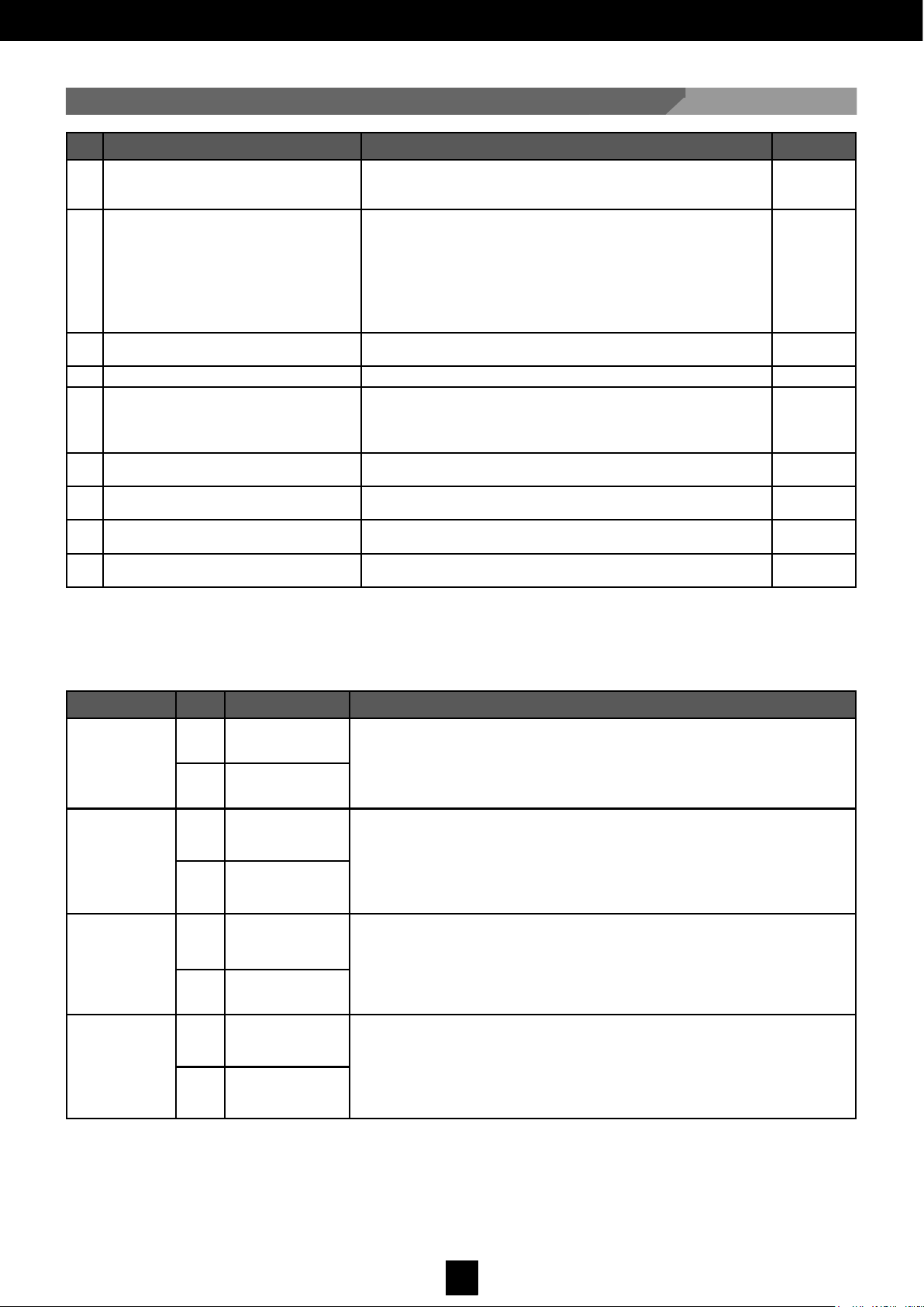
6.2.2 Management of Electronic Locks
ID DESCRIPTION SETTING DEFAULT
09 Electronic lock control voltage
(1)
0 = 12 VDC
1 = 24 VDC
0
10 Types of electronic lock
(2)
0 = Not used
1 = Electronic lock with mechanical reset when closed again
2 = Electromagnetic (maglock) (24VDC only)
3 = Electronic lock
4 = Motorised locked
5 = Electronic lock with automatic reset
6 = Magnetic (maglock) with delay (24VDC only)
0
11 Impulse duration or opening delay
(3)
RANGE: 0 ÷ 9
The time depends on the type of electronic lock
2
12 Closing force of the electronic lock
(4)
RANGE: 0 (min.) ÷ 9 (max.) 5
14
Electronic lock activation according to
the selected logic
(5)
0 = Deactivated
1 = One Radar
2 = Two Radars
3 = One Radar and two Radars
3
15 Configuration of auxiliary input 1
4 = Lock Release Feedback
(6)
5 = Lock Release Control
(7)
0
16 Configuration of auxiliary input 2
4 = Lock Release Feedback
(6)
5 = Lock Release Control
(7)
1
17
Configuration of
auxiliary output 1
5 = Lock control repetition 0
18
Configuration of
auxiliary output 2
5 = Lock control repetition 1
(1) The lock can be operated with 12 and 24 VDC (Parameter 09) with a maximum power of 15 W. Maglocks only operate
with 24 VDC.
(2) The following types of locks are expected to be compatible:
TYPE PAR. VALUE OPERATION
1 - ELECTRON-
IC LOCK WITH
MECHANICAL
RESET WHEN
CLOSED AGAIN
10 1
See Fig. 28 - Electronic lock that when powered in impulsive mode, the leaf is
unlocked and the lock is automatically reset when it closes. It requires a door
jolt freeing device in order to make it easier to unlock the leaf.
11
RANGE: 0÷9
[t=50÷500 ms]
2 - ELECTRO-
MAGNET
(MAGLOCK)
10 2
See Fig. 29 - If the magnet is powered, it keeps the door locked; when disconnected, the door may move freely. It does not require a door jolt freeing device.
The magnet is powered again before the door is fully closed to enable it to
close completely.
11
RANGE: 0÷9
[t=200÷2000 ms]
3 - ELECTRON-
IC LOCK
10 3
See Fig. 30 - Electronic lock that when powered, moves a bolt which keeps the
door locked. When disconnected, the bolt goes up and the leaf can move
freely. It requires a door jolt freeing device in order to make it easier to unlock
the leaf. The magnet is powered again when the door is closed.
11
RANGE: 0÷9
[t=200÷2000 ms]
4 - MOTORISED
LOCK
10 4
See Fig. 31 - Electronic lock with electronic starter motor; when powered, it
retracts the locking arm allowing the leaf to move freely. It requires a door jolt
freeing device in order to make it easier to unlock the leaf. The electronic lock
disconnects when the door is closed.
11
RANGE: 0÷9
[t=500÷5000 ms]
Page 35
34
D00619EN - v0 SWING OPERATOR - INSTALLATION MANUAL
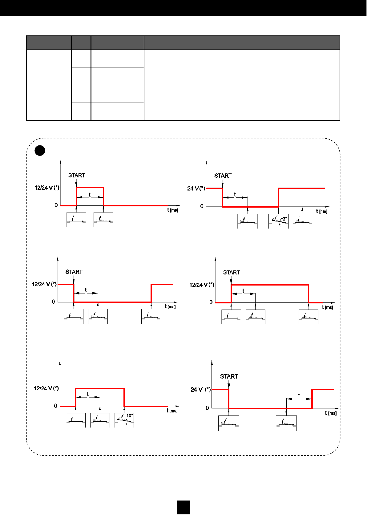
TYPE
PAR. VALUE OPERATION
5 - ELECTRONIC
LOCK WITH AUTOMATIC RESET
10 5
See Fig. 32 - Electronic lock which, when powered, frees the leaf to move.
It resets by cutting power to the lock when the leaf opens more than 10°.
It requires a door jolt freeing device in order to make it easier to unlock
the leaf.
11
RANGE: 0÷9
[t=100÷1000 ms]
6 - ELECTRO-
MAGNETIC
(MAGLOCK)
WITH DELAY
10 6
See Fig. 33 - A magnet that, when powered, keeps the door locked closed
and, when disconnected, frees it to move. It does not require a door jolt freeing device. The magnet is powered again after the leaf is completely closed.
11
RANGE: 0÷9
[t=200÷2000 ms]
6.2
A
Fig. 30.
Fig. 31.
Fig. 32.
Fig. 33.
Fig. 28.
Fig. 29.
Page 36
35
D00619EN - v0 SWING OPERATOR - INSTALLATION MANUAL
6.2.3 Program Switch Connector
6.2.4 External Peripherals Connector (15 VDC)
6.2.5 Double Vector Connection and Use
(3) For some types of electronic locks, the duration of the impulse can be modified to activate or delay the opening of the leaf
with the release control. The parameter has a different significance and level of adjustment according to the type of
electronic lock configured using parameter 10.
(4) To guarantee the electronic lock closes again, the closing force can be adjusted.
(5) The use of the lock (for lock types 2-3-4-6) can be limited only if certain types of operational logic settings have been
selected.
(6) A lock feedback control can be used that indicates the lock release state: after the unlock order is given, the central
electronics wait for permission from the lock before starting to open. If this does not arrive within a maximum set time, the
operator opens the door anyway.
(7) One of the auxiliary inputs may be used as a control to manually release the lock working in parallel with the automatic
release, which can be used to open the door manually.
To connect the program switch (Fig. 21 F), use a shielded cable with 4 0.22 mm wires, not connected to the shield.
For connections, refer to Fig. 30.
For more information on the use of multi-logical program switches, refer to the operating instructions.
The real power supply value may vary from 15 VDC ± 5% depending on the resistive load connected to these terminals.
OUT Terminal / 15 VDC : POSITIVE ( + ) COM Terminal: NEGATIVE ( - )
WARNING: Do not invert the power supply polarity. The LED lit up indicates normal power of 15 V. If it is off, check
that there is mains and/or power.
The Double VECTOR is a connection between two operators for a double swing leaf.
It can be connected in two ways:
1. With two individual VECTORs, each installed in one leaf, but making the connection between the two;
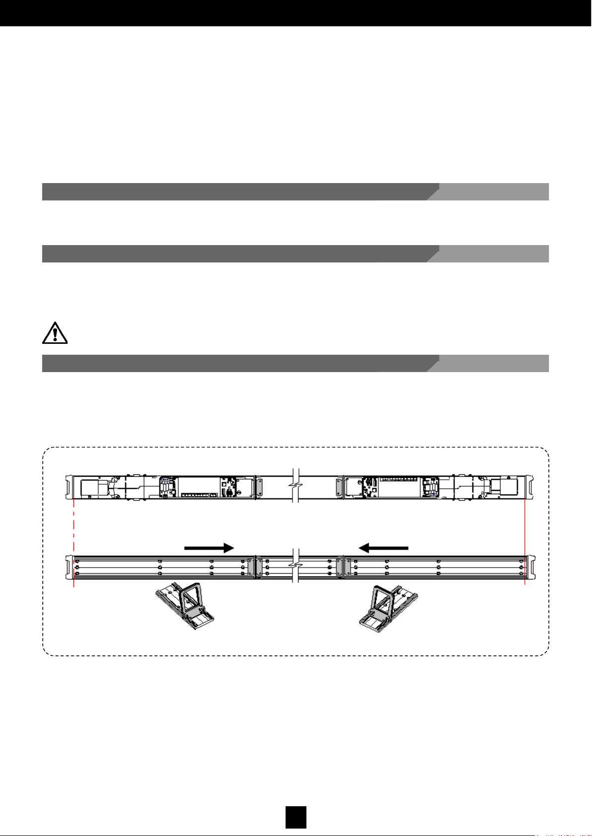
2. With two individual VECTORs joined together with a prolongation kit, as shown in Fig. 34 (OPTIONAL).
The two operators, if not connected together, are independent and can function as individual operators. Using the connection
between the program switch terminal plates, they communicate with each other and interchange the information necessary
for the correct operation of double leaves. The base concept consists of determining a ‘Master’ card that compiles the
operational logic by following precise rules, and a ‘Slave’ card that carries out the orders of the Master.
Fig. 34.
Page 37
36
D00619EN - v0 SWING OPERATOR - INSTALLATION MANUAL
A B
To install the Double VECTOR with the prolongation kit, follow the steps below:
1. Disassemble all of the components attached to the main profiles of each operator.
2. Support against a flat surface the two operator profiles by the ends and against the joining profile, centring them.
3. Insert into the main profile of each operator the lower tab of the joining heads, located at the ends of the central
profile, such that the three profiles are aligned (See Fig. 34)
WARNING: Keep the profiles oriented as indicated in Fig. 34, so that the black heads are placed at the ends.
4. Press the pins (Fig. 34) so that the profiles are joined together.
5. Place the profiles on the wall and make holes suitable for the fixing screws used, following the instructions and the
‘Positioning Levels’ set forth in the previous chapters according to the type of arm to be used.
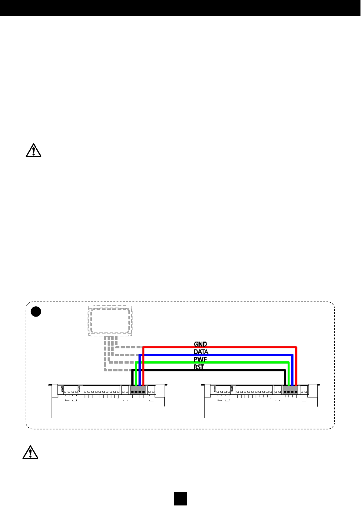
6. Connect the two program switch terminal plates so the two cards can communicate and so that the operator
operates correctly. (Fig. 33)
7. Re-assemble all the components for each one of the Vectors; to do so, insert into the hinge ends of the Master
operator the head located on the prolongation kit with the on switch and logic settings program switch, while on the
opposite part only the head with the on switch.
WARNING: In both cases, select the Master leaf and the Slave leaf before making the connections.
By convention:
MASTER LEAF: First to open, last to close (in the case of a delay) SLAVE LEAF: Last to open, First to close (in the case of a delay)
In both cases, to configure the electronic cards, it is necessary to follow the steps below:
1. It is necessary to configure the corresponding electronic cards using display settings (see section ‘Managing
Operating Parameters of the Display’):
• Configure parameter 13 =1 on the MASTER card.
• Configure parameter 13 =2 on the SLAVE card.
Even for synchronised movement (the leaves open and close at the same time without any delay), it is always necessary to
configure one Master operator and another one as Slave.
WARNING: The two operators must be connected on the same power line and there should be no switches or fuses
between the two operators. The existing peripherals should be connected (KEY, START 1 y START 2) only to the
MASTER. The safety sensors (SAFE OPEN and SAFE CLOSE), in contrast, should be connected and controlled
separately by both cards.
To install the Double VECTOR with two individual Vectors, follow the steps below:
1. Disassemble all of the components attached to the bases of each operator.
2. Attach the bases of each operator to the wall making the necessary holes for each type of screw used in mounting
the operator; follow the instructions and the ‘Positioning Levels’ indicated in the previous chapters, depending on
the type of arm to be used.
3. Connect the two program switch terminals so the two cards can communicate and the operator functions correctly.
(Fig. 33)
4. Re-assemble all the components for each one of the Vectors disconnecting the logic settings program switch from
the slave operator (B).
Page 38
37
D00619EN - v0 SWING OPERATOR - INSTALLATION MANUAL
2. For double leaf with a central stop, it is necessary to configure a delay in the movement of the leaves.
During opening, normally a lesser delay is sufficient, mainly for ‘aesthetic’ reasons (as a maximum, one leaf
‘pushes’ the other a little during the first seconds of opening). When closing, where It is fundamental that one leaf
closes before the other to prevent rubbing, the delay is longer.
If the two leaves are SYNCHRONISED:
• configure only parameter 21 = 0 and parameter 22 = 0 on the MASTER card;
If the two leaves are NOT SYNCHRONISED:
• configure parameter 21 and parameter 22 only on the MASTER card to a value greater than 0.
3. To activate the operators, repeat the steps indicated in the section ‘Commissioning’, ensuring that the acquisition of
the parameters (points 6 and 7) is performed only from the card configured as MASTER.
WARNING: When starting the parameter acquisition task, the Master door begins first. Therefore, it is necessary to
stop the leaf during the next opening it performs. Immediately, the Slave door will start to move; for this, it is also
necessary to stop the leaf at the maximum opening required. Immediately afterwards, both doors will close completely
and the display will flash CL. When both leaves are closed, CL will remain on and the door will be ready for operation.
The program switch (optional) is connected solely and exclusively to the Master card using the same terminal plate used to
connect the two operators together. If the parameters are modified using the program switch, these are identical for both
cards. (Fig. 35) The closing operation begins from the output of both leaves completely open. Each time that a leaf reaches
the completely open position before the other, it will wait until the second one has also reached the completely-open position.
The inverse (START 1 or 2, SAFE CLOSE, anti-crushing) occurs at the same time for both leaves.
Control of the electronic lock with its corresponding operational logic settings is allowed on both cards, exactly as for
individual operators.
The Push&Go function can be activated in both operators, in exactly the same way as for individual operators. When any
attempt to open a leaf is detected by either operator, it will cause both leaves to open.
The anti-crushing and obstacle detection is controlled by both cards, separately and independently.
If anti crushing protection is activated on one card during the closing phase, it will interrupt the movement of both leaves and
they will slowly open completely.
If anti-crushing protection is activated on one card during opening, it will interrupt the movement of the leaf in question and
will slowly close it completely. The other leaf meanwhile, having reached the completely open position, will wait for the leaf in
question before closing.
WARNING: The parameters that can be modified with MilleniumWare are independently on the two cards.
If modifications are made to the movement parameters, it is necessary to ensure the values configured are the same
on both cards to avoid malfunction.
Fig. 35.
6.2
B
LOCK
GND
DATA
PWF
RST
OUT
15VDC
COM
AUX- IN2
AUX- IN1
START 2
START 1
COM
KEY
SAFE - CLOSE
SAFE - OPEN
COM
AUX– OUT2
AUX– OUT1
A
B
A
B
+
-
-
+
MASTER
SLAVE
LOCK
GND
DATA
PWF
RST
OUT
15VDC
COM
AUX- IN2
AUX- IN1
START 2
START 1
COM
KEY
SAFE - CLOSE
SAFE - OPEN
COM
AUX– OUT2
AUX– OUT1
A
B
A
B
+
-
-
+
Page 39
38
D00619EN - v0 SWING OPERATOR - INSTALLATION MANUAL
6.2.7 Connection to a PC
6.2.8 Normal Stop and Emergency Stop
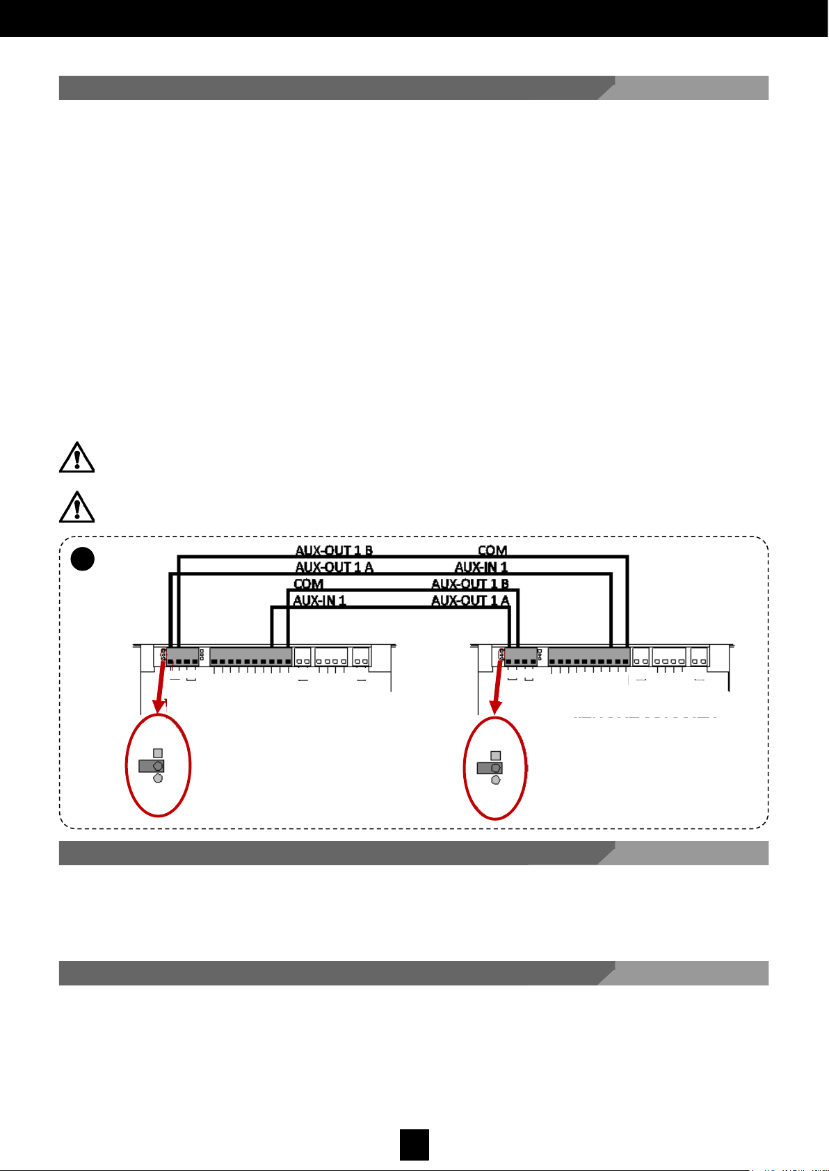
WARNING: For interlocking between two Double VECTORs, the connection will be made between the two MASTER
cards, such that one of the two is considered to be WITH PRIORITY and the other WITHOUT PRIORITY for the
interlocking to function.
WARNING: Remove the jumper located close to the terminal plate on the side of the AUX OUT-1 connector, either the
card with priority or the card without priority (Fig. 36). Installation:.
6.2
C
To connect the operator central control to a Personal Computer (optional), a PC connection card is required. Using the
software MILLENNIUMWARE it is possible to:
• Perform advanced adjustments to some operational parameters
• Obtain advanced diagnostics and information related to the central control
• Program the microprocessor
The normal stop for manusa automatic doors and the starting-up process are carried out automatically. Nevertheless, an
optional emergency stop can be installed.
6.2.6 Interlocking Connection and Use
The VECTOR operator central control is set to be able to operate in interlocking mode through a connection to an electronic
central control of the same class. With the interlocking function, the opening of a door can be done independently, if the other
is not moving, that is, if it is not in a movement phase. To interlock two operators follow these steps (Fig. 33):
• Connect the terminal AUX IN 1 on the card WITH PRIORITY to the terminal AUX OUT 1 - A on the card WITHOUT
PRIORITY
• Connect the terminal COM on the card WITH PRIORITY to the terminal AUX OUT 1 -B on the card WITHOUT PRIORITY
• Connect the terminal AUX OUT 1- A on the card WITH PRIORITY to the terminal AUX IN 1 on the card WITHOUT
PRIORITY
• Connect the terminal AUX OUT 1- B on the card WITH PRIORITY to the terminal COM on the card WITHOUT PRIORITY
Use a 4x0.22 shielded wire for the connections, and do not connect the screen.
When an opening request is simultaneously received from the sensors on both doors, it is necessary to set an opening
priority; to do so, set a door in WITH PRIORITY mode and the other in WITHOUT PRIORITY mode, using the configuration in
each display (see section ‘Managing Operating Parameters of the Display’):
• On the card WITH PRIORITY, configure parameter 15 =2
• On the card WITH PRIORITY, configure the parameter 17 =1
• On the card WITHOUT PRIORITY, configure parameter 15 =3
• On the card WITHOUT PRIORITY, configure parameter 17 =1
If there are simultaneous opening signals, the door WITH PRIORITY mode set will open.
Fig. 36.
WITH PRIORITY
LOCK
GND
DATA
PWF
RST
OUT
15VDC
COM
AUX- IN2
AUX- IN1
START 2
START 1
COM
KEY
SAFE - CLOSE
SAFE - OPEN
COM
AUX– OUT2
A
B
A
B
+
-
-
+
NPN
PNP
NPN
PNP
LOCK
GND
DATA
PWF
RST
OUT
15VDC
COM
AUX- IN2
AUX- IN1
START 2
START 1
COM
KEY
SAFE - CLOSE
SAFE - OPEN
COM
AUX– OUT2
A
B
A
B
+
-
-
+
AUX– OUT1
WITHOUT PRIORITY
AUX– OUT1
Page 40
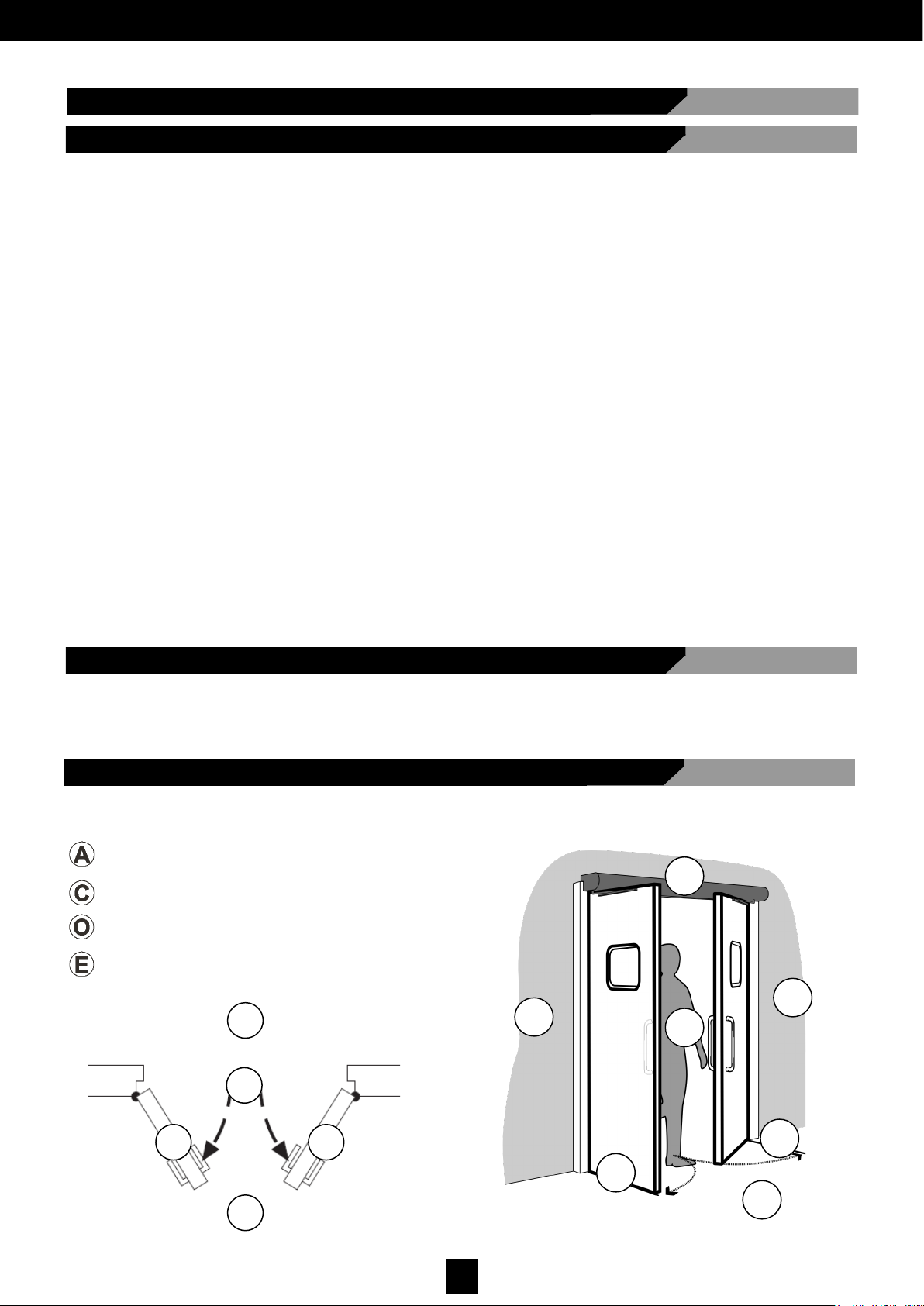
39
D00619EN - v0 SWING OPERATOR - INSTALLATION MANUAL
7 SAFETY
7.3 Identifying Dangerous Areas in the Machine
The opening and closing areas and the operator area have moving parts; they are considered dangerous areas and it is important to know them:
OPENING AREA
CLOSING AREA
OPERATOR AREA
DOOR AREA
C
E
A
A
E
E
O
A A
C
E
E
• Before performing any type of task on the machine, the work area must be checked :
• Keep the area clean and tidy.
• Ensure there is sufficient light.
• Ensure the absence of flammable liquids and gases in and around the work area.
• Clearly signpost the work area to keep away all the people not involved in the work.
• Driving and the use of lifting equipment and accessories:
• Do not drive lifting equipment over people and/or work areas.
• Use lifting and maintenance equipment correctly, with gentle movements and never overload.
• Transport suspended loads through areas of total visibility.
• Wear suitable clothing:
• Do not wear baggy clothes, jewellery, ties or other items that may get caught in moving parts.
• Long hair must be tied back.
• Make use of the necessary PPE (Personal Protection Equipment).
• Avoid stretching:
• Avoid postures that cause fatigue.
• Stand firmly on the ground.
• Never use any part of the machine as a support for people or objects.
• Always be alert:
• Be vigilant.
• Use common sense.
7.1 General Safety Instructions
7.2 Required Personal Protection Equipment
The PPE necessary to safely perform installation and maintenance tasks is:
• Protective gloves.
• Protective shoes against mechanical hazards.
Page 41

40
D00619EN - v0 SWING OPERATOR - INSTALLATION MANUAL
7.4 Risk Assessment
MECHANICAL HAZARDS
Risk Dangerous
Area
Risk Prevention Measures
Structural
Machine area Assess the suitability of the st ructure where the machine is going to be installed:
a levelled floor with sufficient load capacity, no obstacles in the transit area,
firm ground free of irregularities, etc.
Stability
Machine area Attach the different machine parts in a stable way, using appropriate materials and strictly
adhering to the indications in this manual
Shearing, Cut or
Severing
Closing area
• Do not use float glass to manufacture/repair the leaves of the machine.
• Check that there are no burred or sharp edges on any of the different door parts.
Dragging and
entrapment
Inside the
operator
Do not manipulate the interior of the operator while it is in operation.
Impact and
crushing
Closing area
• Adjust the closing force of the machine to a value appropriate for its operation.
• Verify the correct operation of the safety photocell barriers.
Crushing
Machine area Exercise great caution when placing the leaf in its final location.
ELECTRICAL HAZARDS
Hazard Dangerous
Area
Risk Prevention Measures
Direct or indirect
contact
Inside the
operator
• Use components and electrical materials with CE marking.
• Connect the electrical connections, the mains connection, the earth connection and verify
all connections following the indications in the wiring and connections manual.
• Ensure the continuity of the conductors by using cables with sharp edges.
• Perform all maintenance and adjustment tasks by strictly adhering to the specifications in
this manual.
Electrical energy
dispersal
Operator
• Follow the technical instructions applicable under the low-voltage electrotechnical
regulations.
• Connect the electrical connections, the mains connection, the earth connection and verify
all connections following the indications in the wiring and connections manual.
Electromagnetic
compatibility
hazards
Operator
• Use components and electrical materials with CE marking.
• Connect the electrical connections, the mains connection, the earth connection and verify
all connections following the indications in the assembly manual.
HAZARDS RELATED TO CONTROL AND SAFETY DEVICES
Hazard Dangerous
Area
Risk Prevention Measures
Opening controls
Door area
• If manual controls are installed, place them correctly, protected from possible unauthorised
or malicious use.
• Check and install the photocells following the instructions in the assembly, connection and
wiring manuals.
Lack of power
Door area
• Check that the door operates safely again after the power supply has been interrupted.
Confinement
Door area
• Check that the panic break-out system works properly and ensure that the door opens after
power supply failure.
Below, there is an outline of the different hazardous situations that may arise with our machines after leaving the factory, either
during the installation process, commissioning, maintenance, adjustment or disassembly. There is also reference to the risk
minimisation measures that must be taken during the aforementioned phases of the machine’s life:
Page 42
41
D00619EN - v0 SWING OPERATOR - INSTALLATION MANUAL
7.5 Safety Regulations
The safety-improvement measures implemented during the design of the unit are:
• Easy operation.
• Limited number of tools and equipment.
• Easy monitoring.
• Accessibility to internal parts.
• The operators are protected by a metal chassis avoiding unauthorised unauthorized or malicious manipulation
• There are no loose pieces or fastenings coming from the chassis opening.
• Once the chassis is open, the cable to connect to the power supply is easily accessible.
8 MAINTENANCE AND INSPECTION
8.1 General Maintenance to Be Performed by the User
The user’s maintenance duties are limited, exclusively, to keeping the door area clean and tidy.
All maintenance operations, apart from functional tests, must be carried out after disconnecting the power from the
mains.
If the mains cable is damaged, it needs to be replaced by a special set or cable, supplied by the manufacturer or by
your after-sales services.
Installation, maintenance, adjustment and repair tasks should only be carried out by technical staff authorised by .
CARACTERÍSTICAS MECÁNICAS.
8.2 Maintenance Tasks Exclusively Reserved for the Manufacturer
If the program manager detects anomalies in the door operation, the operator includes various protective measures to prevent
major system damage.
The different system errors are shown in 7 segment displays to signal operating conditions:
In the majority of cases, t o resume door operation it w il l be enough to se lect the door open mode and then
th e autom atic door m ode. If after this operation the anomaly persists, it will be necessary to resort to a
ma nusa authorised service technician.
9 TROUBLESHOOTING
SIGNAL DESCRIPTION
OP on Door open
OP Flashing Door opening
CL on Door closed
CL Flashing Door closing
E1 Error derived from not initiating the system parameters (self-learning)
E2
Device type (Dip 5), or arm type (Dip 1 or configuration of the arm in the passive brake card)
selection error
E3/E4 Maximum current threshold exceeded error (OVER CURRENT)
E6 Supervised sensors error
E8 Coder connection error
Only original spare parts must be used.
Page 43
42
D00619EN - v0 SWING OPERATOR - INSTALLATION MANUAL
CARACTERÍSTICAS MECÁNICAS
10 APPENDIXES
CARACTERÍSTICAS MECÁNICAS
10.1 CE Declaration of Conformity
DECLARATION OF CONFORMITY
Manufacturer: MANUSA DOOR SYSTEMS
Address: Av. Vía Augusta, 85-87, 6ª planta
08174 – Sant Cugat del Vallès
Barcelona, Spain
Tel 902 321 400
Fax 902 321 450
www.manusa.com
Product: Operator for pedestrian automac swing doors
Model: VECTOR
Ref: A06473
We herein declare, under our sole responsibility, that the products listed and referenced comply with the following European Direcves:
2006/42/CE Machinery Direcve
305/2011/CE Construcon Products Regulaon
2004/108/CE Electromagnec Compability Direcve
2006/95/CE Low Voltage Direcve
It has also implemented the following harmonised standards and technical specicaons:
Technical Building Code. Basic Document SUA. Operaon Safety and Accessibility
Technical Building Code. Basic Document SI. Fire Safety
UNE 85121 EX
UNE-EN 61000, 6-2, 6-3
UNE-EN 60335-2-103
UNE EN 16005
The CE marking is included in the product to indicate conformity with the essenal requirements of the applicable direcves. This declaraon of conformity means that the machine installaon and start-up has been made in accordance with
the assembly, operaon and maintenance instrucons from the manufacturer.
Josep Mª Guilera Francesca Marnez
CEO Product Standardizaon
Sant Cugat del Vallès, June 2017
Page 44
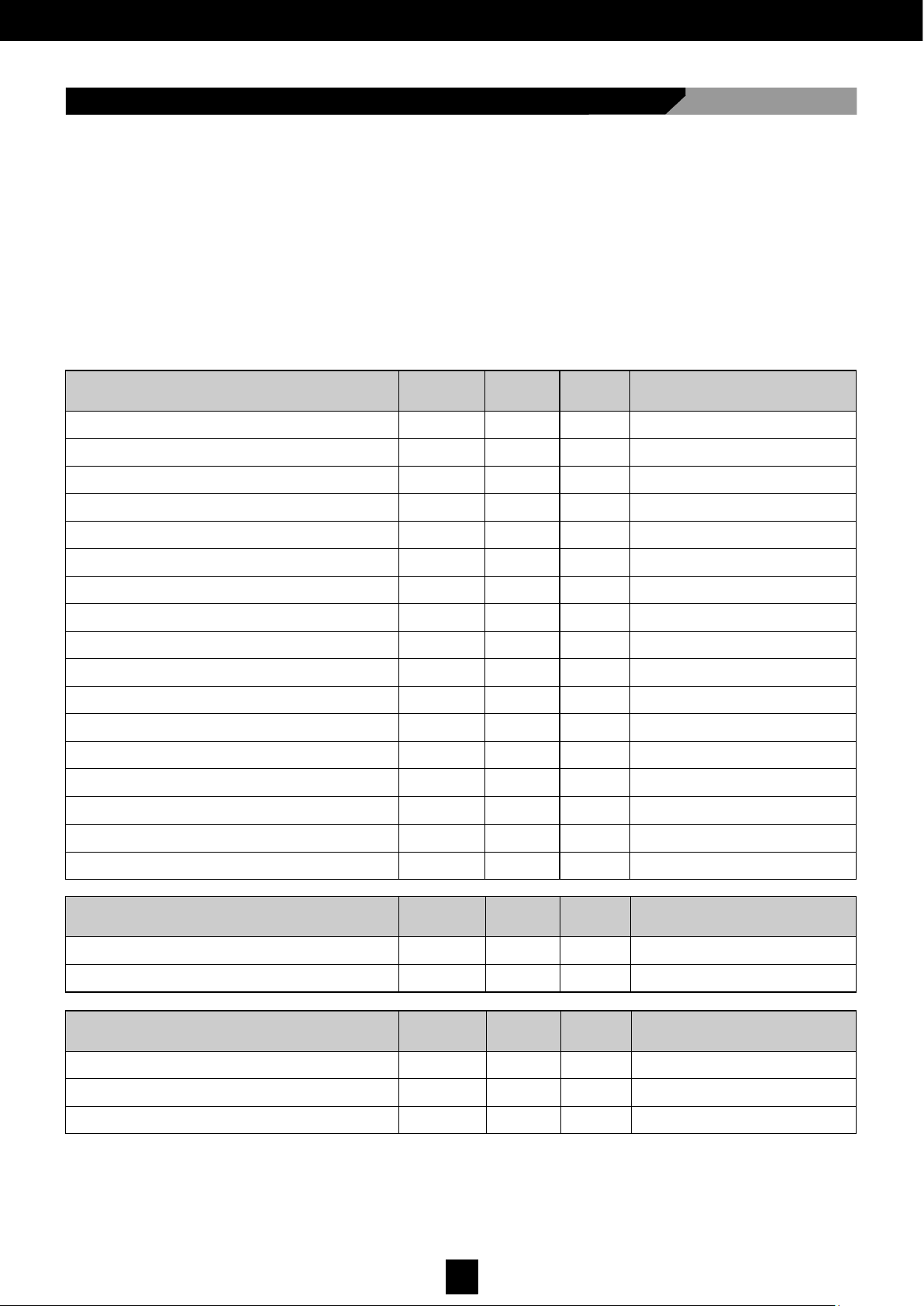
43
D00619EN - v0 SWING OPERATOR - INSTALLATION MANUAL
10.2 Installation Checklist
Compliance with safety requirements is a primary
objective for manusa, given that hundreds of thousands of people in more than 70 countries pass
through our doors daily.
Risk assessment for manu sa doors is not
limited to the design and industrialisation activities carried out at our factory, but encompasses the entire useful life of our products,
guaranteeing the health and safety of the users at each stage of the lifecycle of the door .
Please place here the identifying
sticker for the installation
Mechanical/Electrical Elements
Compliance Non-
compliance
Not
applicable
Observations
Fixing the operator on-site
Position of the Dragging / Pushing operator
Cover and external caps
Axis and arm
Fasteners and suspension of leaves
Spring load level (EN4-EN5-EN6)
Condition of the leaves
Wiring
Low Energy parameter
Push & Go parameter
Dragging / Pushing parameter
Actuator S (spring) / M (motor) parameter
Acceleration parameter
Waiting times parameter
Lock parameter
Auxiliary I/O configuration
Peripheral controls (selector/outside key switch…)
Safety and Control Elements:
Compliance Non-
compliance
Not
applicable
Observations
Sistemas de accionamiento (radar…)
Sensores de seguridad
Documentation:
Compliance Non-
compliance
Not
applicable
Observations
Instructions manual submitted
Works delivery certificate submitted
Maintenance contract submitted
Page 45
44
D00619EN - v0 SWING OPERATOR - INSTALLATION MANUAL
CARACTERÍSTICAS MECÁNICAS
10.3 Maintenance Book
10.3.1 Action Frequency
Frequency for swing doors: 12 months
NOTA: Table complies with UNE 85121EX
Without power (neither electric nor batteries, if present)
Clean and grease turning pieces, hinges, etc.
Check the strength of support points
Adjust screws
With power
Check the correct operation of the safety elements
Page 46
45
D00619EN - v0 SWING OPERATOR - INSTALLATION MANUAL
10.3.2 Actions Log
Date …… / ..… / .…... PSV No.………………………
Signed Manusa Signed Customer
Date …… / ..… / .…... PSV No.………………………
Signed Manusa Signed Customer
Date …… / ..… / .…... PSV No.………………………
Signed Manusa Signed Customer
Date …… / ..… / .…... PSV No.………………………
Signed Manusa Signed Customer
Date …… / ..… / .…... PSV No.………………………
Signed Manusa Signed Customer
Date …… / ..… / .…... PSV No.………………………
Signed Manusa Signed Customer
Date …… / ..… / .…... PSV No.………………………
Signed Manusa Signed Customer
Date …… / ..… / .…... PSV No.………………………
Signed Manusa Signed Customer
Date …… / ..… / .…... PSV No.………………………
Signed Manusa Signed Customer
Date …… / ..… / .…... PSV No.………………………
Signed Manusa Signed Customer
Date …… / ..… / .…... PSV No.………………………
Signed Manusa Signed Customer
Date …… / ..… / .…... PSV No.………………………
Signed Manusa Signed Customer
Date …… / ..… / .…... PSV No.………………………
Signed Manusa Signed Customer
Date …… / ..… / .…... PSV No.………………………
Signed Manusa Signed Customer
Page 47

46
D00619EN - v0 SWING OPERATOR - INSTALLATION MANUAL
CARACTERÍSTICAS MECÁNICAS
10.4 Notes
Page 48
The characteristics detailed in this document are for information only and do not represent any contractual
obligation. The manufacturer reserves the right to make modifications without prior warning
HEAD OFFICE
Av. Vía Augusta, 85-87, 6ª
08174 Sant Cugat del Vallés
Barcelona - Spain
Tel. +34 902 321 400
Fax +34 902 321 450
 Loading...