

Page 1
1
D00729EN - v2 DDS-SSENSOR - INSTALLATION MANUAL
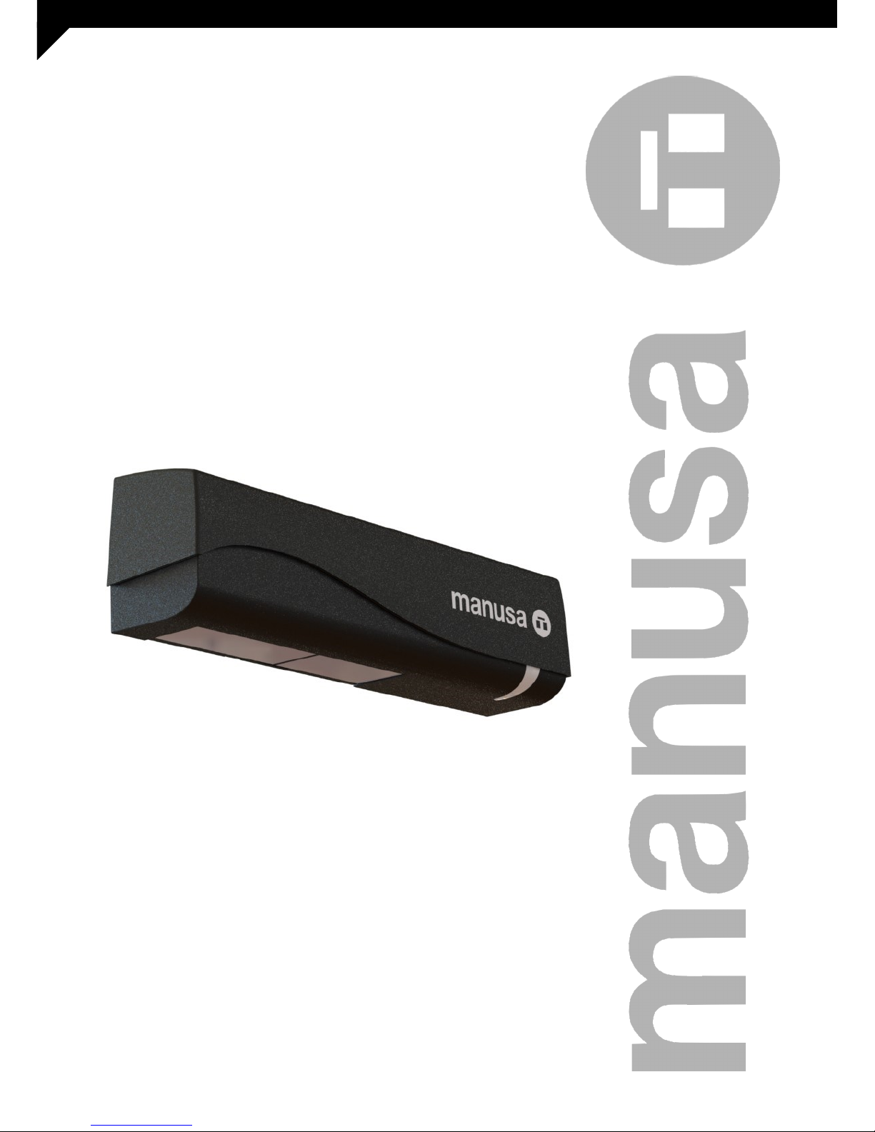
Installation Manual
DDS-S SENSOR
Page 2
2
D00729EN - v2 DDS-SSENSOR - INSTALLATION MANUAL
TRANSLATED DOCUMENT
CONTENTS
1 DESCRIPTION
2 COMMISSIONING
2.1 MOUNTING
3 USER MENU
4 TROUBLESHOOTING
5 INSTALLATION CHECKLIST
6 MAINTENANCE
6.1 MAINTENANCE TO BE CARRIED OUT BY THE USER
6.2 MAINTENANCE RESTRICTED TO THE MANUFACTURER
7 DECLARATION CE OF CONFORMITY
INSTALLATION MANUAL
DDS-S SENSOR
This manual has been compiled according to standard
UNE-EN-ISO 12100.
Read thoroughly all of these instructions before using
the unit.
This manual includes all the necessary information
required to install the product
Keep this manual in a safe place for future reference.
1 DESCRIPTION
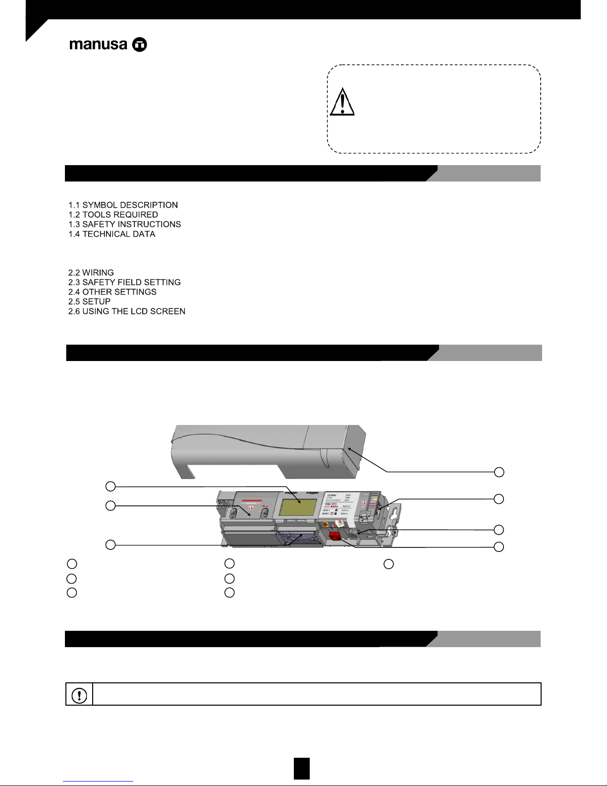
The AIR DPS Sensor is an electro-sensitive device for the detection of individuals, specifically designed to provide safety to
Manusa sliding doors. This sensor complies with all the requirements specified in the Standard EN 16005.
4
LCD screen
Infrared curtain setting
Infrared lenses
Cover
Main connector
Main settings button
Infrared angle setting button
4
5
6
7
5
6
7
2
1
3
1
2
3
The symbol that appear in this manual is the next:
1.1 SYMBOL DESCRIPTION
IMPORTANT WARNING. Strict ly adher e to the ind icaons pr ovided with this symbol.
Page 3
3
D00729EN - v2 DDS-SSENSOR - INSTALLATION MANUAL
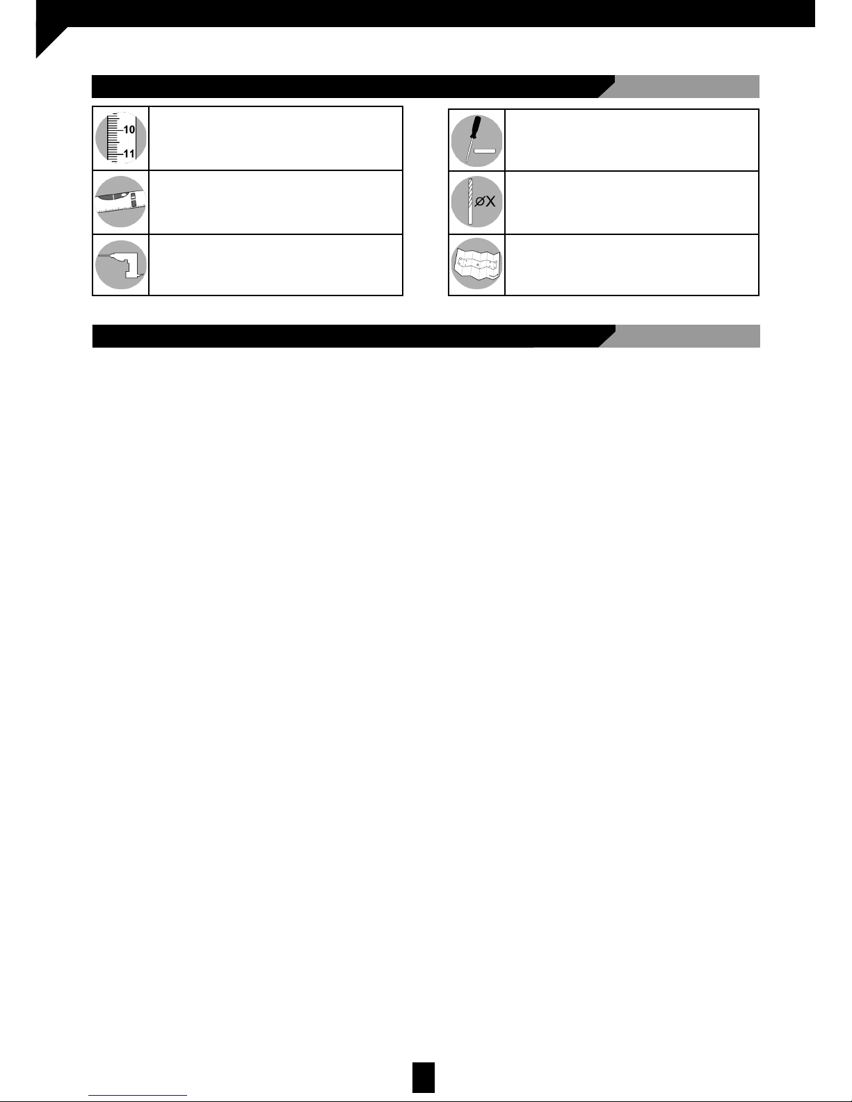
Tape measure
Spirit level
Drill
Flathead screwdriver
Drill Bits:
Ø 3
Ø 8
Mounting template
1.2 TOOLS REQUIRED
1.3 SAFETY INSTRUCTIONS
All national and international provisions relating to door safety must be observed. The installation and commissioning of the
sensor should only be carried out by authorised technical staff. Any servicing or repair works on the sensor should only be
carried out by manusa.
Any other use of the device different from its intended purpose shall be excluded from the manufacturer’s guarantee.
This device may only be operated with protective low voltage (SELV) with safe electrical insulation.
The installing company shall be responsible for the correct installation of the sensor and the door safety elements.
The manufacturer shall not be liable for incorrect sensor installations or inappropriate settings which have not been
implemented by manusa.
When handling the sensor, great care must be taken in order not to interfere with its correct operation.
Page 4
4
D00729EN - v2 DDS-SSENSOR - INSTALLATION MANUAL
1.4 TECHNICAL DATA
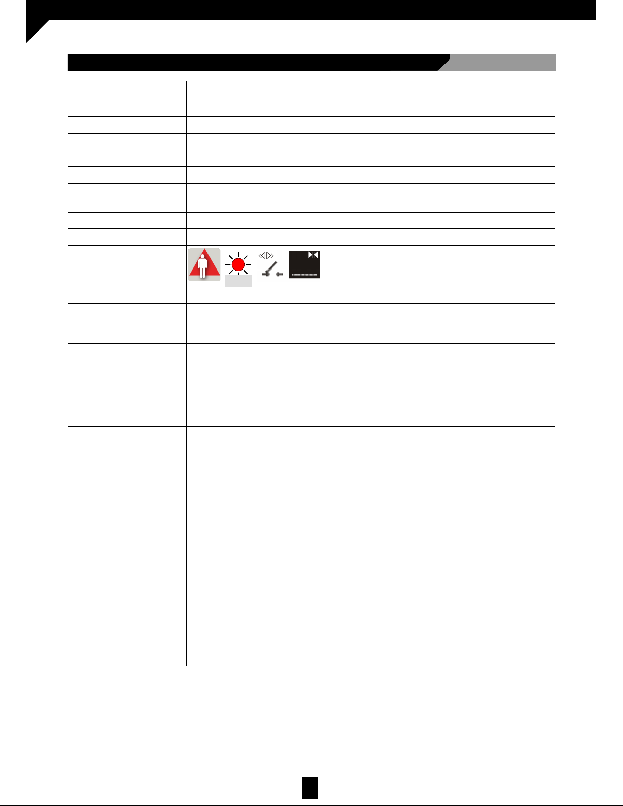
Power supply
12V - 30V DC +/-10%
To be operated from SELV-compatible power supplies only
Power consumption < 2.5W
Mounting height 2 to 3.5 m (internal regulations may affect the acceptable mounting height)
Operating temperature -25° up to 55° C; 0 at 95% RH, without condensation
Protection class IP54
Noise <70 dB
Useful life 20 years
Applicable directives EMC 2004/108/EC; MD 2006/42/EC; ROHS 2002/95/EC
Detection mode
Presence
Technology Infrared active with environmental scanning
Spot: 5cm x 5cm (typical)
Spots per curtain: max 24.
Number of curtains: 2
Input Pulse polarity: positive or negative (adjustable)
Impedance:
Positive pulse: 2K to earth
470R to the ‘+’ of the power source
Pulse voltage: from 6V to 30V
Pulse duration: from 4µs to 500µs
Work cycle: Max. 50%
Output Pulse polarity: negative
Level:
No detection: Pulse between the ‘+’ of the power source and 0V
Detection: the “+“ of the power source
Topology: open collector with 4.7K to 3.3V
Maximum sink current: 25mA with 1K external resistance towards 24V
Optional: Solid-state relay (without potential or polarity)
Maximum current output: 100mA
Max. circuit-breaking capacity: 42V AC/DC
Certification EN 12978
EN ISO 13849-1:2008 PL “c“
(on the condition that the door controller monitors the sensor at least once for every door cycle)
EN 16005:2012 Chapter 4.6.8
DIN 18650-1;2010 Chapter 5.7.4
BS 7036-1:1996 Chapter 8.1
Reaction time <200ms (max. 500ms)
Infrared angle points setting -7° up to +3.5º
Red
Page 5
5
D00729EN - v2 DDS-SSENSOR - INSTALLATION MANUAL
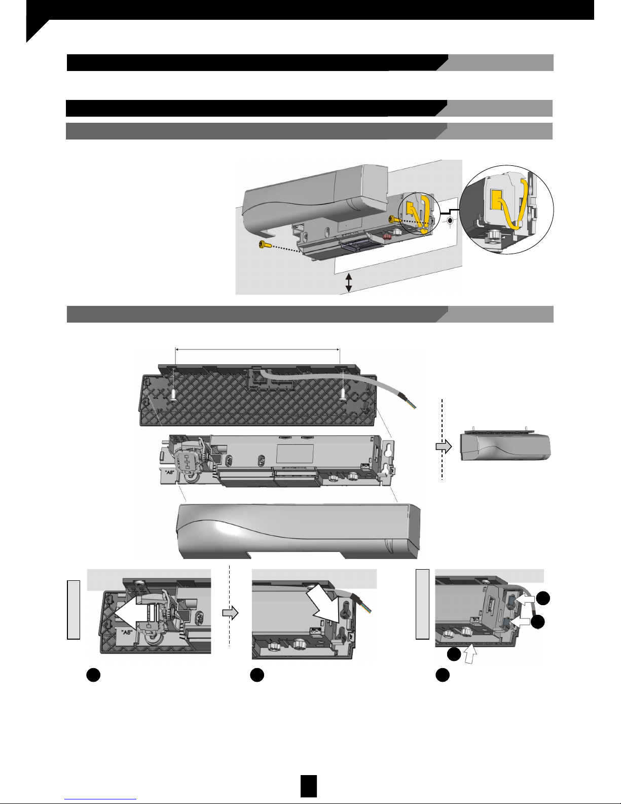
2 COMMISSIONING
The recommended commissioning sequence is as follows: installation, connection, start-up and settings.
2.1 MOUNTING
Max 5cm
2.1.2 SURFACE MOUNTING (OPTIONAL)
136 mm
2.1.1 STANDARD MOUNTING
Slide
1
Clip
2
Unclip
1
Presionar
1.1
1.1
1.2
MOUNT
DISMOUNT
1. Remove the protective cover
2. Connect the cable
3. Position the drilling template
4. Drill the holes and remove the template
5. Pass the cable through and install
the sensor
Page 6
6
D00729EN - v2 DDS-SSENSOR - INSTALLATION MANUAL
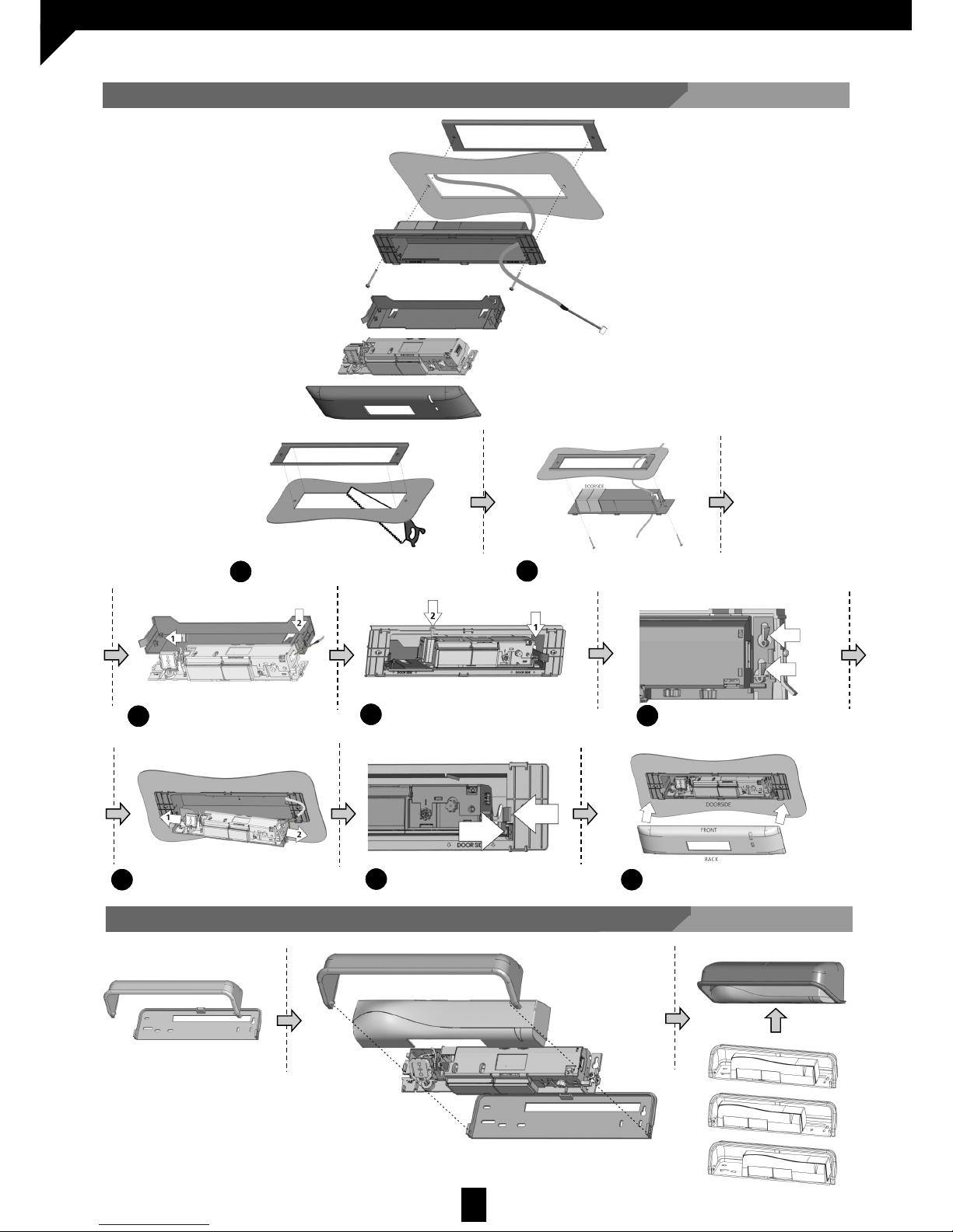
Cut
1
Screw together
2
Clip
3
Clip
4
Unclip
5
Clip
6
Unclip
7
Clip
8
2.1.4 MOUNTING WITH RAIN PROTECTION (OPTIONAL)
2.1.3 CEILING MOUNTING (OPTIONAL)
Page 7
7
D00729EN - v2 DDS-SSENSOR - INSTALLATION MANUAL
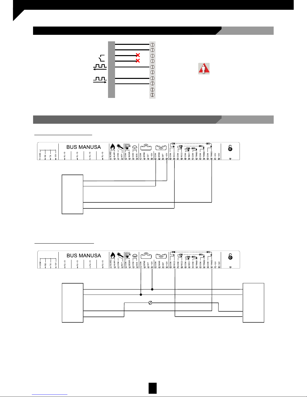
2.2 WIRING
Sensor
DDS-S
2.2.1.a Connection to a sensor
POWER SUPPLY
OPENING INPUT
SAFETY OUTPUT
SAFETY INPUT
PULL-UP**
*Output condition when the sensor is in operation.
** Bravo only, connect to 12V
VERDE
MARRÓN
AMARILLO
BLANCO
ROSA
GRIS
VIOLET
SENSOR
12-30V
AC-DC
*
2.2.1 CONNECTION TO VISIO OPERATOR FOR OPENING PROTECTION
Brown
Green
Pink
Grey
Note:
Configure the following parameter:
PULSE INPUT = positive
Sensor 1
Brown
Green
Pink
Grey
DDS-S
2.2.1.b Connecting two sensors
Note:
Configure the following parameters:
Sensor 1:
PULSE INPUT = positive
Sensor 2:
PULSE INPUT = negative
Sensor 2
Brown
Green
Pink
Grey
DDS-S
Page 8
8
D00729EN - v2 DDS-SSENSOR - INSTALLATION MANUAL
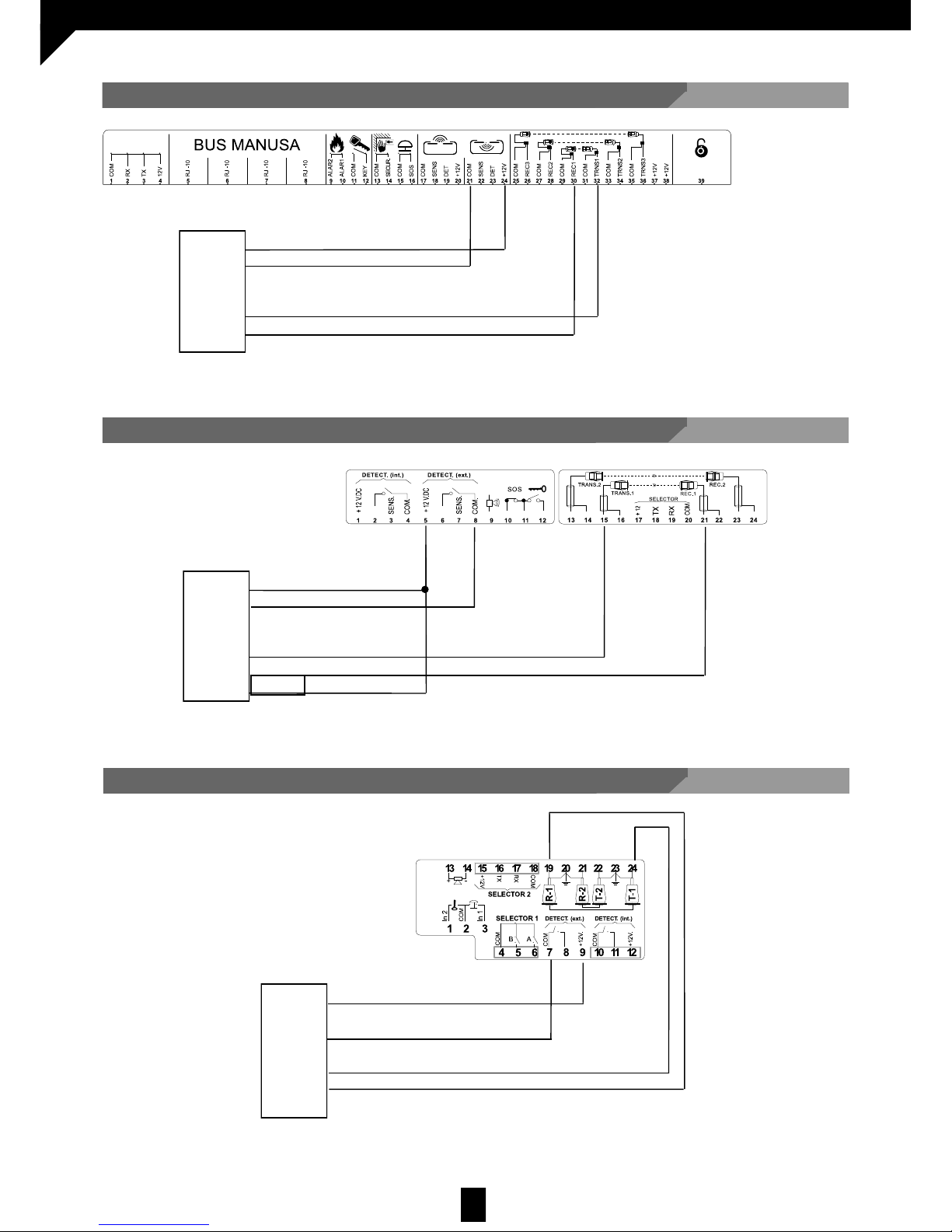
2.2.3 CONNECTION TO BRAVO OPERATOR FOR CLOSING PROTECTION
Note:
Configure the following parameters:
PULSE INPUT = positive
Violet
2.2.4 CONNECTION TO ACTIVA OPERATOR FOR CLOSING PROTECTION
Sensor
Gris
Note:
Configure the following parameters:
PULSE INPUT = positive
2.2.2 CONNECTION TO VISIO OPERATOR FOR CLOSING PROTECTION
Sensor
Brown
Green
Pink
Grey
DDS-S
Note:
Configure the following parameter:
PULSE INPUT = positive
DDS-S
DDS-S
Brown
Green
Pink
Grey
Sensor
Brown
Green
Pink
Page 9
9
D00729EN - v2 DDS-SSENSOR - INSTALLATION MANUAL
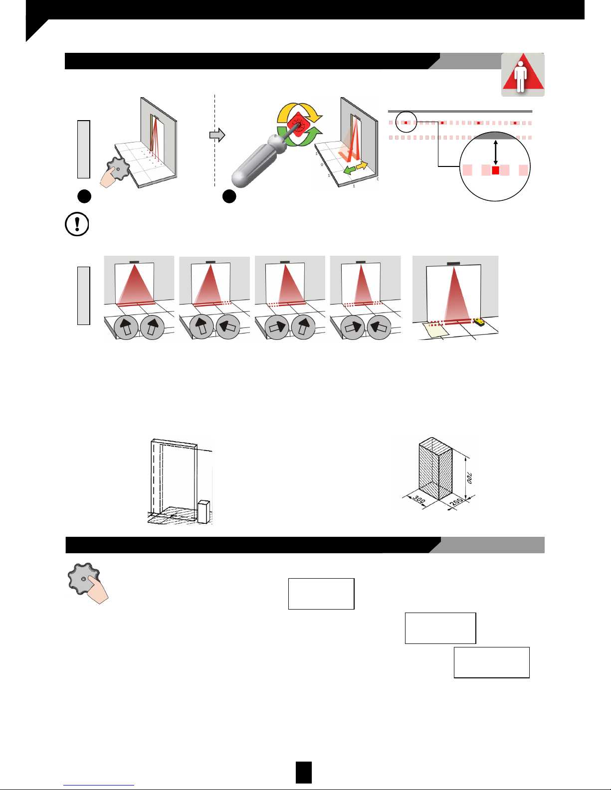
2.3 SAFETY FIELD SETTING - INFRARED
Press twice to activate the
visible spot.
1
If necessary, adjust the angle of the
infrared curtains (from -7º to +4º)
2
Part of the emitted field can be covered in order to reduce the detection field.
The position of the arrow determines the field width.
Always check the field width with a
piece of paper and not with the
Spotfinder, that detects the entire
emitted field.
Possible
additional
settings
through
the LCD.
≤ 9 cm
*Visibility depends on external conditions. If the spots are not visible, the Spotfinder helps to locate the position of the curtains.
**The distance between the inner curtain of the inside door sensor and the inner curtain of the outside door sensor should al ways be
less than 20cm
The distance up to the door leaf depends therefore on the thickness of the door leaf.
CLOSER
FARTHER
2.4 OTHER SETTINGS
Set the sensor by LCD or choose one of the presettings:
1.- STANDARD: indoor mounting
2.– CRITICAL ENVIRONMENT: critical or outside installations
3.– SHOPPING STREET: Installations in narrow streets with pedestrian traffic
Presettings
Standard
Presettings
Critical env.
Presettings
Shopping str.
ANGLE WIDTH
x2
The size of the detection fields varies depending on the mounting height and the settings of the sensor. The sensor should
cover the whole travel path of the door leaf/leaves. To verify, use the reference body as per EN 16005 (reference body
dimensions: 700x300x200mm).
Cuerpo de referencia
Page 10
10
D00729EN - v2 DDS-SSENSOR - INSTALLATION MANUAL
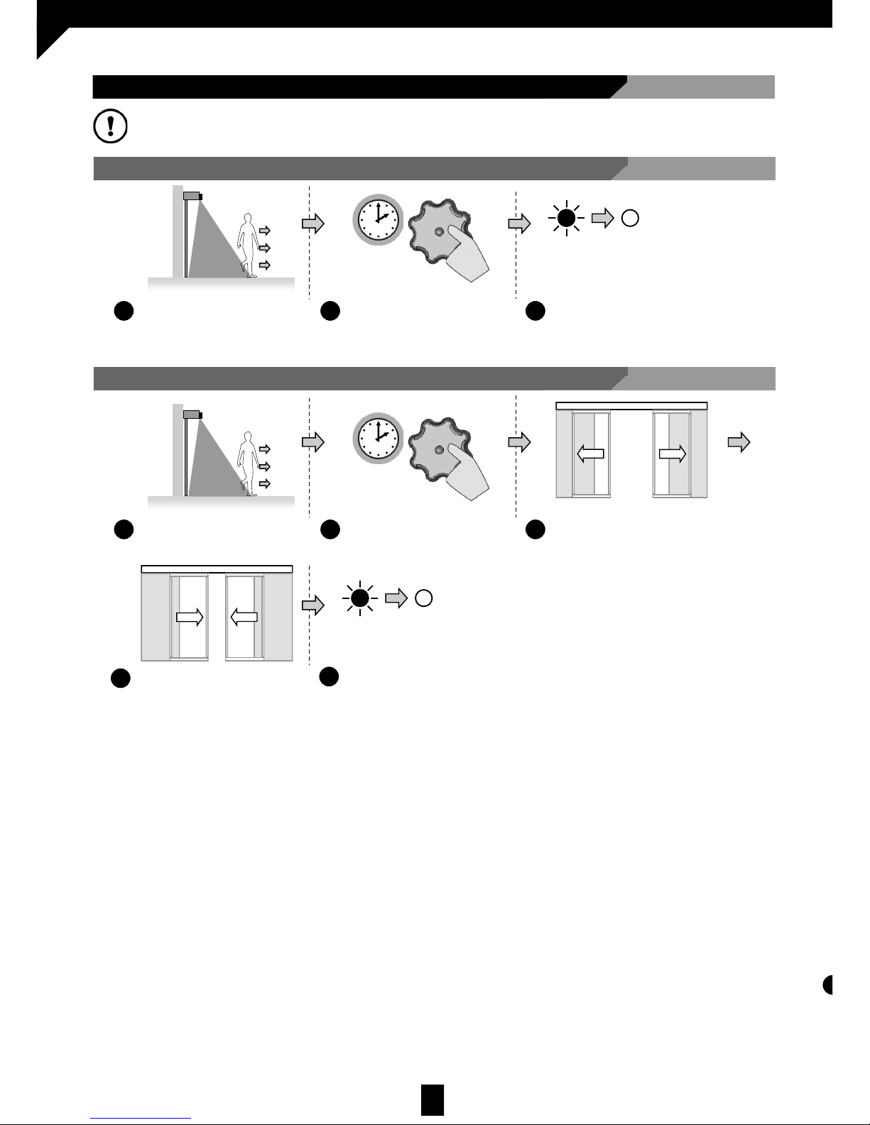
2.5 SETUP
Vacate the detection field
1
4
Press for 2s
2
2s
Vacate the detection field
1
Press for 4s
2
4s
= OK
When the LED switches off,
the sensor is ready for use
3
The door performs an opening
manoeuvre.
3
The door performs an closing
manoeuvre.
4
= OK
When the LED switches off,
the sensor is ready for use
5
2.5.1 QUICK SETUP
2.5.2 ASSISTED SETUP
After SETUP, check that the installation operates correctly before signing off on the setup process.
IMPORTANT! After DDS-S setup do a self learning procedure for door automation (Visio)
Page 11
11
D00729EN - v2 DDS-SSENSOR - INSTALLATION MANUAL
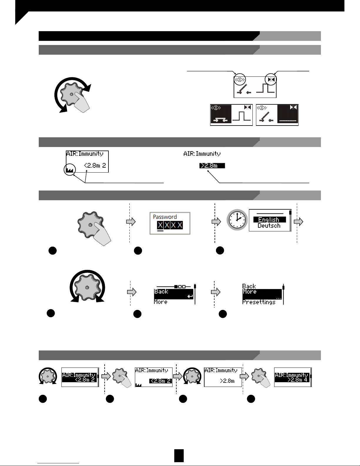
2.6 USING THE LCD SCREEN
Scroll through the parameters
1
Press to select the
parameter
2
Scroll through the
values. More values
are displayed.
3
Press to save the
value.
4
2.6.1 INSTRUCTIONS DURING NORMAL OPERATION
To adjust the contrast,
simultaneously press and turn the
grey button
Opening impulse
Safety
Negative display = Active output
2.6.2 FACTORY VALUE vs. SAVED VALUE
Displayed value = Factory value Displayed value = Saved value
2.6.3 NAVIGATING THE MENUS
2.6.4 CHANGING VALUES
Press to access the menu
1
Enter password if required.
Not during the first minute after
the detector comes ON
2
Scroll through the menu items
4
Select BACK to return to the
previous menu or display
5
Select MORE to continue to
the next level:
Basic menu.
Advanced menu.
Diagnostics menu.
6
Select language before
entering the first menu.
During the first 30s after switching
the sensor on or later in the
diagnostics menu.
3
30s
Page 12
12
D00729EN - v2 DDS-SSENSOR - INSTALLATION MANUAL
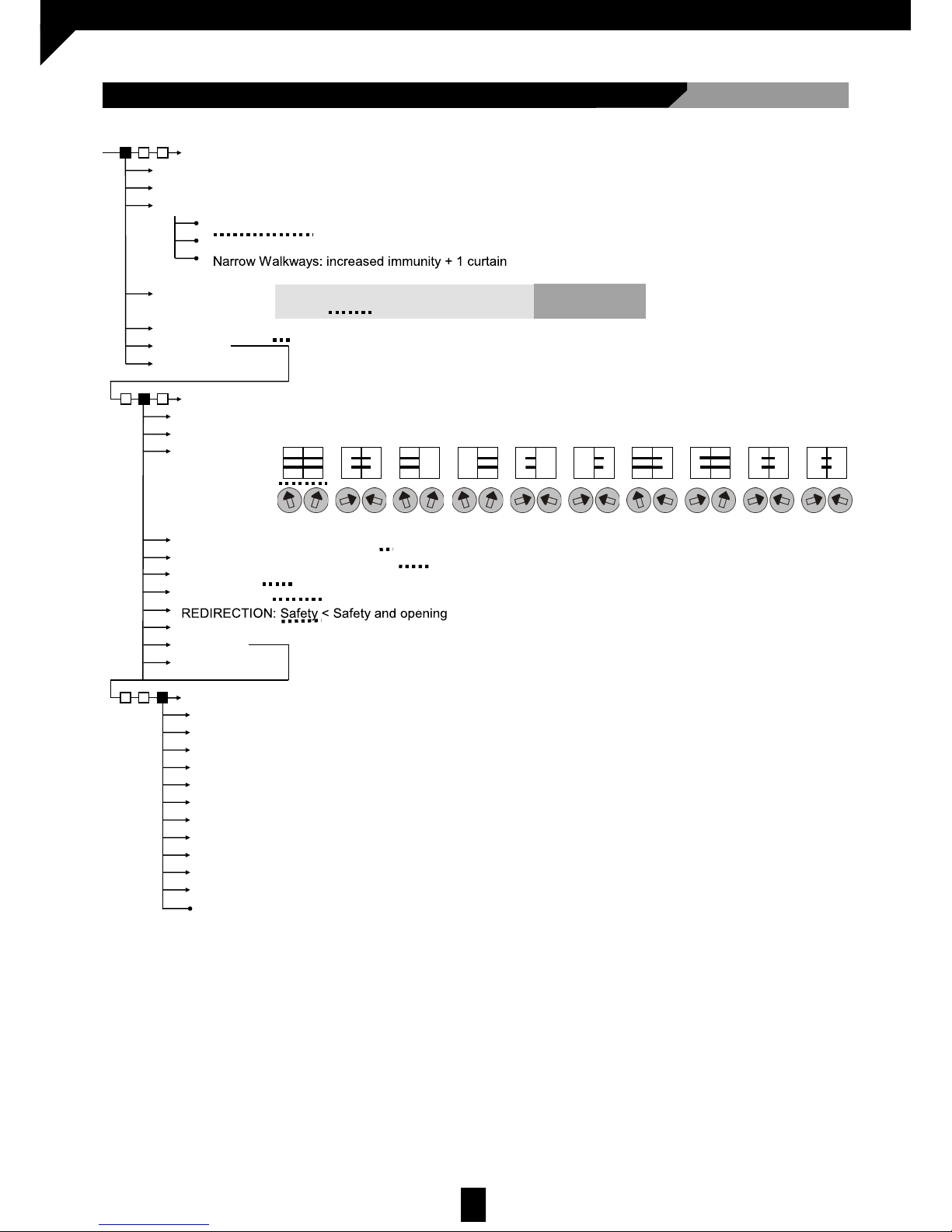
NAVIGATION MAP:
ZIP: All values in compressed format
ID#: Unique identification number
ERRORS the last 10 errors
AIR: SPOTVIEW View of the spots that trigger detection
AIR: C1 ENERG. Signal amplitude received from curtain 1
AIR: C2 ENERG. Signal amplitude received from curtain 2
POWER SUPPLY Connector power supply
OPERATINGTIME Power duration since first startup
RESET LOG Delete all saved errors
RC PASSWORD Password for remote control login
LANGUAGE. LCD menu language
3 USER MENU
DIAGNOSTICS
ADMIN Enter code to access the Administrator mode
BASIC MENU
Back
Next
PRESETTINGS
IR: WIDTH
Next
PULSE INPUT. Positive < Negative
FACTORY VALUES <full reset < partial reset
Standard: factory values
Critical Environment: increased immunity
IR: FREQUENCY. A < B. Detectors installed close together should have different frequencies.
Next
ADVANCED MENU
Back
Back
IR: NUMBER Service mode < 1 < 2
IR: TPOMAXP. Motion < 15s < 30s < 1min < 2 min < 5 min < 10 min < 20 min < 60 min < infinite
Next
Back
For conformity with EN 16005 / DIN 18650, use values 6
y 7 at a mounting height ≥ 2,8m.
BS7036: for a mounting height ≥ 2,2m use values 6 y 7.
* Values 4 and 5 exclude the door from complying with
EN 16005 / DIN 18650 / BS 7036
IR: IMMUNITY.
< 2,8 m
It is always necessary to adjust the position of the arrows with a screwdriver.
Service mode = Detections deactivated 15 min for maintenance tasks.
This value excludes compliance of the door systems with EN 16005 and with DIN 18650
IR: OUTPUT. Pulse
DIN 18650 ≥ 1min
EN 16005 ≥ 30 sec
> 2,8 m
Partial reset: Outputs do not reset
(1)Low<(2)Normal<(3)High<(4)+High*<(5)++High*< (6)Normal< (7)High
Page 13
13
D00729EN - v2 DDS-SSENSOR - INSTALLATION MANUAL
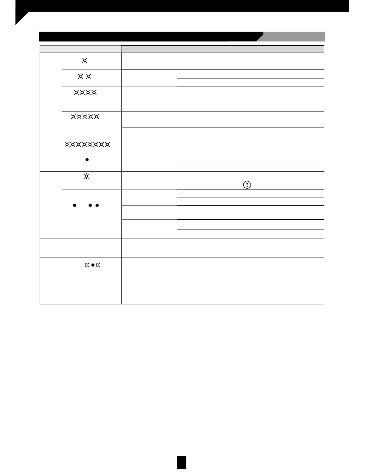
4 TROUBLESHOOTING
LED STATUS
Error Solution
ORANGE
Flashes once
The sensor signals an
internal fault
1. Replace the sensor.
Flashes twice
The power supply is too low or
too high.
1. Check the power supply in the diagnostics menu.
2. Check the wiring.
Flashes 4 times
The sensor is not receiving
sufficient infrared energy.
1. Check the angle of the infrared curtains.
2. Increase the AIR immunity filter: values >2.8m.
3. Deactivate 1 curtain.
Flashes 5 times
The sensor is receiving too
much infrared energy.
1. Check the angle of the infrared curtains.
2. Decrease the AIR immunity filter: values 1-3<2.8m.
The sensor receives outside
interference.
1. R emove t he cause of the i nt erference (fluorescent.. .)
Flashes 8 times
The AIR emitter is defective.
1. Replace the sensor.
ON
Problem with the sensor
memory.
1. Switch the power supply OFF and ON again.
2. If the LED comes on again, replace the sensor.
RED
Flashes rapidly after
assisted setup
The sensor sees the door
during assisted SETUP
1. Check the angle of the infrared curtains.
2. Perform another assisted SETUP. Vacate the detection field!
Turns on sporadically
The sensor vibrates
1. Check that the sensor is correctly installed.
2. Check the position of the cable and the casing.
The sensor sees the door
1. Perform another assisted SETUP and change the angle of the infrared curtains.
The sensor is disrupted by
external conditions
1. Increase the AIR immunity filter: value 3.
2. Select presetting 2 or 3.
--
LED and LCD are OFF
--
1. Check the wiring.
--
¿ ?
The door reaction does not
correspond to the LED signal
--
1. Check the output configuration value.
2. Check the wiring.
--
LCD or remote control is not
responding
The sensor is
password-protected.
Enter password. If you have forgotten the password, cut and re-establish the power
supply in order to access the sensor; do not enter the password during the first
minute.
Page 14
14
D00729EN - v2 DDS-SSENSOR - INSTALLATION MANUAL
6 MAINTENANCE
6.1 MAINTENANCE TO BE CARRIED OUT BY THE USER
Maintenance of sensors may only be carried out by technically authorised staff. The maintenance tasks reserved for
the user are, exclusively, maintaining cleanliness and order around the door area.
Installation, maintenance, adjustment and repairing tasks on the AIR-DPS sensor are exclusively restricted to technical staff
authorised by .
6.2 MAINTENANCE RESTRICTED TO THE MANUFACTURER
It is recommended to clean the optical parts whenever necessary and, in any case, at least once a year, with
a slightly-damp cloth.
DO NOT use aggressive cleaning products.
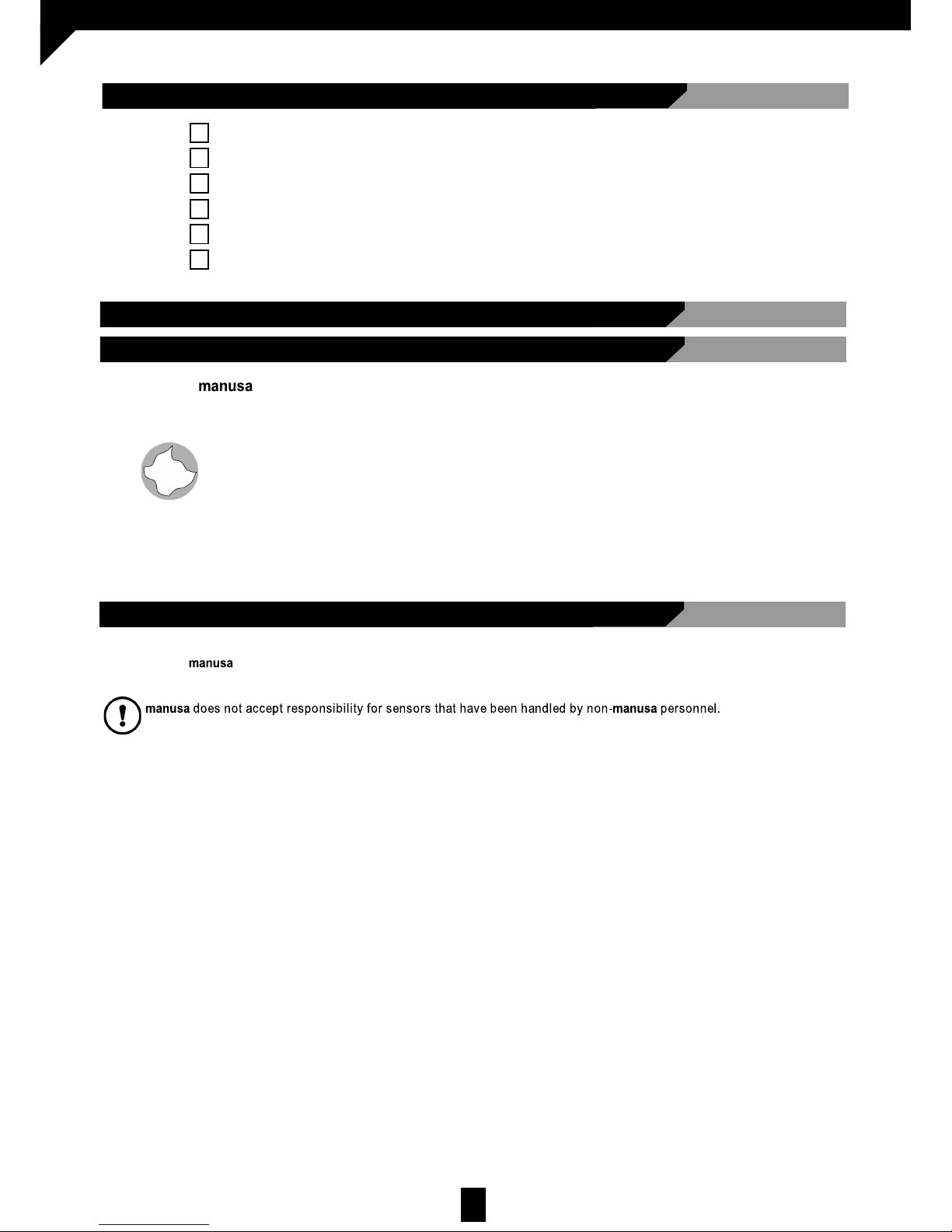
5 INSTALLATION CHECKLIST
Check that the sensor has been firmly installed to avoid external vibrations.
Do not cover the sensor.
There are no moving objects or light sources in the detection field.
There are no reflective objects (mirrors, stainless steel objects…) in the IR area.
The operator cover is perfectly fitted.
The complete installation set: door + sensors + other accessories, are all working correctly.
Dispose of the sensor appropriately at the end of its useful life.
Page 15
15
D00729EN - v2 DDS-SSENSOR - INSTALLATION MANUAL
7 EC DECLARATION OF CONFORMITY
Manufacturer: MANUSA
Address: Av. Vía Augusta, 85-87, 6
th
Floor
08174 – Sant Cugat del Vallès
Barcelona, Spain
Tel 902 321 400
Fax 902 321 450
www.manusa.com
Product: Electro-sensive device for the detecon of the presence of individuals, suitable for installaon in automac pedestri-
an doors.
Model: DDS-S SENSOR
Ref: A05039
Noed body: TÜV NORD CERT GmbH, Langemarckstrasse 20, D-45141 Essen, NB 0044,
EC-type-examinaon cercate No. 44 799 12 405836-001.
We herein declare, under our sole responsibility, that the product listed and referenced complies with the following European Direcves:
2006/42/CE Machinery Direcve
305/2011/CE Construcon Products Regulaon
2004/108/CE Electromagnec Compability Direcve
2006/95/CE Low-voltage Equipment Direcve
2011/65/CE RoHS2 Direcve
It has also applied the following harmonised standards and technical specicaons:
EN 16005
UNE-EN 12978
AS 5007
DIN 18650
BS 7036
UNE-EN ISO 13849. Performance level PL “c”
Authorised representave: MANUSA DOOR SYSTEMS
Av. Vía Augusta, 85-87, 6
th
Floor , 08174 – Sant Cugat del Vallès, Barcelona, Spain
Tel: 902 321 400 Fax: 902 321 450
www.manusa.com
The CE marking is included in the product to indicate conformity with the essenal requirements of the applicable direcves.
This declaraon of conformity means that the machine installaon and commissioning has been made in accordance with the
assembly, operaon and maintenance instrucons from the manufacturer.
Josep Mª Guilera Francesca Marnez
General Manager Product Standardisaon
Sant Cugat del Vallès, September 2014
DECLARATION CE OF CONFORMITY
Page 16

16
D00729EN - v2 DDS-SSENSOR - INSTALLATION MANUAL
HEAD OFFICE
Av. Vía Augusta, 85-87, 6
th
Floor
08174 Sant Cugat del Vallés
Barcelona - España
Tel. +34 902 321 400
Fax +34 902 321 450
www.manusa.com
NOTE: The characteristics detailed in this document
are for information only and do not represent any contractual obligation.
The manufacturer reserves the right to make modifications
without prior warning
Last revision: July 2015
42.8445 – V1 / 03.2015
 Loading...