

Manufacture Technology GEFXL2-CSW28KX User Manual

GEFXL2-CSW28KX
User’s Manual


i
GEFXL2-CSW28KX
User's Manual
24-port GbE L2 Switch with10 GbE uplink
Release 1.00
2011, Manufacture Corporation. All rights reserved. All brand and product names are trademarks or registered
trademarks of their respective companies
Publication date: March, 2012
Revision A1

ii
About This Manual
Copyright
.
Purpose
Audience
CONVENTIONS
WARRANTY
Disclaimer
FCC Warning
Copyright © 2011 Manufacture Technology Corp. All rights reserved.
The products and programs described in this User’s Manual are licensed
products of Manufacture Technology, This User’s Manual contains proprietary
information protected by copyright, and this User’s Manual and all
accompanying hardware, software and documentation are copyrighted. No
parts of this User’s manual may be copied, photocopied, reproduced,
translated or reduced to any electronic medium or machine-readable from by
any means by electronic or mechanical. Including photocopying, recording, or
information storage and retrieval systems, for any purpose other than the
purchaser’s personal use, and without the prior experess written permission
of Manufacture Technology.
This manual gives specific information on how to operate and use the
management functions of the GEFXL2-CSW28KX
The Manual is intended for use by network administrators who are
responsible for operating and maintaining network equipment;
consequently, it assumes a basic working knowledge of general
switch functions, the Internet Protocol (IP), and Simple Network
Management Protocol (SNMP).
The following conventions are used throughout this manual to
show information.
See the Customer Support/ Warranty booklet included with the
product. A copy of the specific warranty terms applicable to your
Manufacture products and replacement parts can be obtained from
your Manufacture Sales and Service Office authorized dealer.
Manufacture Technology does not warrant that the hardware will
work properly in all environments and applications, and marks no
warranty and representation, either implied or expressed, with
respect to the quality, performance, merchantability, or fitness for
a particular purpose. Manufacture disclaims liability for any
inaccuracies or omissions that may have occurred. Information in
this User’s Manual is subject to change without notice and does not
represent a commitment on the part of Manufacture. Manufacture
assumes no responsibility for any inaccuracies that may be
contained in this User’s Manual. Manufacture makes no
commitment to update or keep current the information in this
User’s Manual, and reserves the righter to make improvements to
this User’s Manual and /or to the products described in this User’s
Manual, at any time without notice.
This equipment has been tested and found to comply with the
limits for a Class B digital device, pursuant to Part 15 of the FCC
Rules. These limits are designed to provide reasonable protection
against harmful interference when the equipment is operated in a
commercial environment. This equipment generates, uses, and can
radiate radio frequency energy and, if not installed and used in
Publication date: March, 2012
Revision A1
iii
NOTE: Emphasizes important information or calls your
attention to related features or instructions.
W
ARNING
:
Alerts you to a potential hazard that could cause
personal injury.
C
AUTION
:
Alerts you to a potential hazard that could cause
loss of data, or damage the system or equipment.
FCC Caution
CE mark
Warning
accordance with the Instruction manual, may cause harmful
interference to radio communications.
To assure continued compliance (example-use only shielded
interface cables when connection to computer or peripheral
devices). Any changes or modifications not expressly approved by
the party responsible for compliance could void the user’s
authority to operate the equipment. This device complies with Part
15 of the FCC Rules. Operation is subject to the Following two
conditions: (1) This device may not cause harmful interference,
and (2) this device must accept any interference received,
including interference that may cause undesired operation.
This is a Class B device, In a domestic environment, this product
may cause radio interference, in which case the user may be
required to take adequate measures.
Publication date: March, 2012
Revision A1

iv
Table of Contents
Revision History ......................................................................................................................................... viii
INTRODUCTION ................................................................................................................................................ 1
CHAPTER 1 OPERATION OF WEB-BASED MANAGEMENT ......................................................... 2
CHAPTER 2 SYSTEM CONFIGURATION ......................................................................................... 4
2-1 SYSTEM INFORMATION ................................................................................................................................. 4
2-1.1 Information .......................................................................................................................................... 4
2-1.2 Configuration ....................................................................................................................................... 8
2-2 TIME ............................................................................................................................................................. 9
2-2.1 Manual ................................................................................................................................................. 9
2-2.2 NTP .................................................................................................................................................... 11
2-3 ACCOUNT ................................................................................................................................................... 12
2-3.1 Users .................................................................................................................................................. 12
2-3.2 Privitege Level ................................................................................................................................... 14
2-4 IP ................................................................................................................................................................ 17
2-4.1 IPV4 ................................................................................................................................................... 17
2-4.2 IPV6 ................................................................................................................................................... 19
2-5 SYSLOG ...................................................................................................................................................... 21
2-5.1 Configuration .................................................................................................................................... 21
2-5.2 Log .................................................................................................................................................... 22
2-5.3 Detailed Log ..................................................................................................................................... 23
2-6 SNMP ........................................................................................................................................................ 24
2-6.1 System ............................................................................................................................................... 24
2-6.2 Communities ...................................................................................................................................... 26
2-6.3 Users .................................................................................................................................................. 27
2-6.4 Groups ............................................................................................................................................... 29
2-6.5 Views .................................................................................................................................................. 30
2-6.6 Access ................................................................................................................................................ 32
2-6.7 Tarp .................................................................................................................................................... 34
CHAPTER 3. CONFIGURATION ........................................................................................................ 36
3-1 PORT ........................................................................................................................................................... 36
3-1.1 Configuration ..................................................................................................................................... 36
3-1.2 Port Description ................................................................................................................................ 38
3-1.3 Traffic Overview ................................................................................................................................. 39
3-1.4 Detailed Statistics .............................................................................................................................. 41
3-1.5 Qos Statistics ...................................................................................................................................... 44
3-1.6 SFP Information ................................................................................................................................ 45
3-1.7 EEE .................................................................................................................................................... 47
3-2 ACL ........................................................................................................................................................... 49
3-2.1 Ports ................................................................................................................................................... 49
3-2.2 Rate Limiters ...................................................................................................................................... 52
3-2.3 Access Control List ............................................................................................................................ 54
3-2.4 ACL Status ......................................................................................................................................... 57
3-3 AGGREGATION ............................................................................................................................................ 59
3-3.1 Static Trunk ........................................................................................................................................ 59
3-3.1.1 Static Trunk .................................................................................................................................................. 59
3-3.2 LACP ................................................................................................................................................. 61
3-3.2.1 Configuration ............................................................................................................................................... 61
3-3.2.2 System Status ............................................................................................................................................... 63
3-3.2.3 Port Status .................................................................................................................................................... 64
3-3.2.4 Port Statistics ............................................................................................................................................... 65
3-4 SPANNING TREE .......................................................................................................................................... 66
3-4.1 Bridge Settings ................................................................................................................................... 66
2-4.2 MSTI Mapping ................................................................................................................................... 69
3-4.3 MSTI Priorities .................................................................................................................................. 71
3-4.4 CIST Ports ......................................................................................................................................... 72
3-4.5 MSTI Ports ......................................................................................................................................... 74
3-4.6 Bridge Status ...................................................................................................................................... 76
3-4.7 Port Status .......................................................................................................................................... 77
Publication date: March, 2012
Revision A1

v
3-4.8 Port Statistics ..................................................................................................................................... 78
3-5 MRSTP ...................................................................................................................................................... 79
3-5.1 Instance .............................................................................................................................................. 79
3-5.2 Port Configuration ............................................................................................................................. 81
3-5.3 Port Status .......................................................................................................................................... 83
3-6 IGMP SNOOPING ........................................................................................................................................ 85
3-6.1 Basic Configuration ........................................................................................................................... 85
3-5.2 VLAN Configuration .......................................................................................................................... 88
3-5.3 Port Group Filtering .......................................................................................................................... 90
3-5.4 Status .................................................................................................................................................. 92
3-5.5 Group Infermation ............................................................................................................................. 94
3-5.6 IPv4 SSM information ........................................................................................................................ 95
3-6 MLD SNOOPING ......................................................................................................................................... 97
3-6.1 Basic Configuration ........................................................................................................................... 97
3-6.2 VLAN Configuration ........................................................................................................................ 100
3-6.3 Port Group Filtering ........................................................................................................................ 102
3-6.4 Status ................................................................................................................................................ 103
3-6.5 Group Infermation ........................................................................................................................... 105
3-6.6 IPv6 SSM Information ..................................................................................................................... 107
3-7 MVR ........................................................................................................................................................ 109
3-7.1 Configuration ................................................................................................................................... 109
3-7.2 Groups Information .......................................................................................................................... 111
3-7.3 Statistics ........................................................................................................................................... 112
3-8 LLDP ....................................................................................................................................................... 113
3-8.1 LLDP Configuration ........................................................................................................................ 113
3-8.2 LLDP Neighbours ............................................................................................................................ 116
3-8.3 LLDP-MED Configuration .............................................................................................................. 118
3-8.4 LLDP-MED Neighbours .................................................................................................................. 125
3-8.5 EEE .................................................................................................................................................. 128
3-8.6 Port Statistics ................................................................................................................................... 130
3- 9 FILTERING DATA BASE ............................................................................................................................. 132
3- 9.1 Configuration .................................................................................................................................. 132
3- 9.2 Dynamic MAC Table ....................................................................................................................... 135
3-10 VLAN .................................................................................................................................................... 136
3-10.1 VLAN Membership ......................................................................................................................... 136
3-10.2 Ports ............................................................................................................................................... 138
3-10.3 Switch Status .................................................................................................................................. 140
3-10.4 Port Status ...................................................................................................................................... 142
3-10.5 Private VLANs ............................................................................................................................... 144
3-10.5.1 Private VLANs Membership ............................................................................................................... 144
3-10.5.2 Port Isolation ......................................................................................................................................... 146
3-10.6 MAC-based VLAN .......................................................................................................................... 147
3-10.6.1 Configuration ........................................................................................................................................ 147
3-10.6.2 Status ..................................................................................................................................................... 149
3-10.7 PROTOCOL -BASED VLAN ................................................................................................................... 150
3-10.7.1 Protocol to Group ................................................................................................................................. 150
3-10.7.2 Group to VLAN ..................................................................................................................................... 152
3-12 GARP ..................................................................................................................................................... 154
3-12.1 Configuration ................................................................................................................................. 154
3-12.2 Statistics ......................................................................................................................................... 156
3-13 GVRP ..................................................................................................................................................... 157
3-13.1 Configuration ................................................................................................................................. 157
3-13.2 Statistics ......................................................................................................................................... 159
3-14 MRP ....................................................................................................................................................... 160
3-14.1 Configuration ................................................................................................................................. 160
3-14.2 Statistics ......................................................................................................................................... 162
3-15 MVRP .................................................................................................................................................... 163
3-15.1 Configuration ................................................................................................................................. 163
3-15.2 Statistics ......................................................................................................................................... 165
3-16 QOS ........................................................................................................................................................ 166
3-16.1 Port Classification ......................................................................................................................... 166
3-16.2 Port Policing .................................................................................................................................. 168
3-16.3 Port Scheduler ............................................................................................................................... 169
3-16.4 Port Shaping .................................................................................................................................. 172
Publication date: March, 2012
Revision A1

vi
3-16.5 Port Tag Remarking ....................................................................................................................... 176
3-16.6 Port DSCP ..................................................................................................................................... 178
3-16.7 DSCP-Based QoS .......................................................................................................................... 180
3-16.8 DSCP Translation ................................................................................................ .......................... 182
3-16.9 DSCP Classification ...................................................................................................................... 184
3-16.10 QoS Control List Configuration ................................................................................................... 185
3-16.11 QCL Status ................................................................................................................................... 190
3-16.12 Storm Control ............................................................................................................................... 192
3-18 S-FLOW AGENT ...................................................................................................................................... 193
3-18.1 Collector ........................................................................................................................................ 193
3-18.2 Sampler .......................................................................................................................................... 195
3-19 MIRRORING ............................................................................................................................................ 197
3-20 TRAP EVENT SEVERITY .......................................................................................................................... 199
3-21 SMTP CONFIGURATION .......................................................................................................................... 200
3-22 802.3AH OAM ........................................................................................................................................ 201
3-22.1 Port Config .................................................................................................................................... 201
3-22.2 Event Config .................................................................................................................................. 203
3-22.3 Port Status ...................................................................................................................................... 205
3-22.4 Link Events ..................................................................................................................................... 207
3-22.5 Statistics ......................................................................................................................................... 210
3-23 ETHERNET OAM .................................................................................................................................... 212
3-23 EPS ........................................................................................................................................................ 214
3-23 ERPS ...................................................................................................................................................... 216
3-22 PTP ........................................................................................................................................................ 218
3-22.1 Configuration ................................................................................................................................. 218
3-22.2 Status .............................................................................................................................................. 221
CHAPTER 4. SECURITY ............................................................................................................. 223
4-1 IP SOURCE GUARD ................................................................................................................................... 223
4-1.1 Configuration ................................................................................................................................... 223
4-1.2 Static Table ....................................................................................................................................... 225
4-1.3 Dynamic Table ................................................................................................................................. 227
4-2 ARP INSPRCTION ...................................................................................................................................... 228
4-2.1 Configuration ................................................................................................................................... 228
4-2.2 Static Table ....................................................................................................................................... 230
4-2.3 Dynamic Table ................................................................................................................................. 232
4-3 DHCP SNOOPING ..................................................................................................................................... 233
4-3.1 Configuration ................................................................................................................................... 233
4-3.2 Statistics ........................................................................................................................................... 234
4-4 DHCP RELAY ........................................................................................................................................... 236
4-4.1 Configuration ................................................................................................................................... 236
4-4.2 Statistics ........................................................................................................................................... 238
4-5 NAS ......................................................................................................................................................... 240
4-5.1 Configuration ................................................................................................................................... 240
4-5.2 Switch Status .................................................................................................................................... 248
4-5.3 Port Status ........................................................................................................................................ 250
4-6 AAA ......................................................................................................................................................... 253
4-6.1 Configuration ................................................................................................................................... 253
4-6.2 Radius Overview .............................................................................................................................. 257
4-6.3 Radius Details .................................................................................................................................. 259
4-7 PORT SECURITY ........................................................................................................................................ 260
4-7.1 Limit Control .................................................................................................................................... 260
4-7.2 Switch Status .................................................................................................................................... 263
4-7.3 Port Status ........................................................................................................................................ 265
4-8 ACCESS MANAGEMENT ............................................................................................................................ 266
4-8.1 Configuration ................................................................................................................................... 266
4-8.2 Statistics ........................................................................................................................................... 268
4-9 SSH ................................ .......................................................................................................................... 269
4-10 HTTPS ................................................................................................................................................... 270
4-11 AUTH METHOD ....................................................................................................................................... 271
CHAPTER 5. MAINTENANCE .................................................................................................. 272
5-1 RESTART DEVICE ...................................................................................................................................... 272
Publication date: March, 2012
Revision A1

vii
5-2 FIRMWARE ................................................................................................................................................ 273
5-2.1 Firmware Upgrade .......................................................................................................................... 273
5-2.2 Firmware Selection .......................................................................................................................... 274
5-3 SAVE / RESTORE ....................................................................................................................................... 276
5-3.1 Factory Defaults .............................................................................................................................. 276
5-3.2 Save Start ......................................................................................................................................... 276
5-3.3 Save User ......................................................................................................................................... 277
5-3.4 Restore User .................................................................................................................................... 277
5-4 EXPORT / IMPORT ...................................................................................................................................... 278
5-4.1 Export Config ................................................................................................................................... 278
5-4.2 Import Config ................................................................................................................................... 279
5-5 DIAGMOSTICS ........................................................................................................................................... 280
5-5.1 Ping .................................................................................................................................................. 280
5-5.2 Ping6 ................................................................................................................................................ 282
5-5.3 VeriPHY ........................................................................................................................................... 283
A. GLOSSARY OF WEB-BASED MANAGEMENT ................................................................................... 284
A .................................................................................................................................................................... 284
C ..................................................................................................................................................................... 286
D .................................................................................................................................................................... 286
E ..................................................................................................................................................................... 287
F ..................................................................................................................................................................... 288
H .................................................................................................................................................................... 289
I ...................................................................................................................................................................... 289
L ..................................................................................................................................................................... 291
M .................................................................................................................................................................... 291
N .................................................................................................................................................................... 293
O .................................................................................................................................................................... 293
P ..................................................................................................................................................................... 294
Q .................................................................................................................................................................... 296
R ..................................................................................................................................................................... 296
S ..................................................................................................................................................................... 297
T ..................................................................................................................................................................... 299
U .................................................................................................................................................................... 300
V .................................................................................................................................................................... 301
Publication date: March, 2012
Revision A1

viii
Release
Date
Revision
V0.95
11/12/2011
A1
Revision History
Publication date: March, 2012
Revision A1

1
INTRODUCTION
Overview
In this user’s manual, it will not only tell you how to install and connect your
network system but configure and monitor the GEFXL2-CSW28KX through the built-in
CLI and web by (RS-232) serial interface and Ethernet ports step-by-step. Many
explanations in detail of hardware and software functions are shown as well as the
examples of the operation for web-based interface and command-line interface (CLI).
The GEFXL2-CSW28KX series, the next generation L2+ managed switches from
Manufacture, is a portfolio of affordable managed switches that provides a reliable
infrastructure for your business network. These switches deliver more intelligent
features you need to improve the availability of your critical business applications,
protect your sensitive information, and optimize your network bandwidth to deliver
information and applications more effectively. It provides the ideal combination of
affordability and capabilities for entry level networking includes small business or
enterprise application and helps you create a more efficient, better-connected workforce.
GEFXL2-CSW28KX L2+ Managed Switches provide 20 ports (100/1G) SFP + 4-P
Combo Gigabit TP/(100/1G)SFP and 4-P (1G/10G) SFP+ in a single device; the
specification is highlighted as follows.
L2+ features provide better manageability, security, QoS, and performance.
High port count design with all Gigabit Ethernet ports
Support guest VLAN, voice VLAN, Port based, tag-based and Protocol based
VLANs.
Support 802.3az Energy Efficient Ethernet standard
Support 32K MAC table
Support IPv6/ IPv4 Dual stack
Support s-Flow
Support Easy-Configuration-Port for easy implement the IP Phone, IP Camera
or Wireless environment.
Overview of this user’s manual
Chapter 1 “Operation of Web-based Management”
Chapter 2 “Maintenance”
Publication date: March, 2012
Revision A1
2
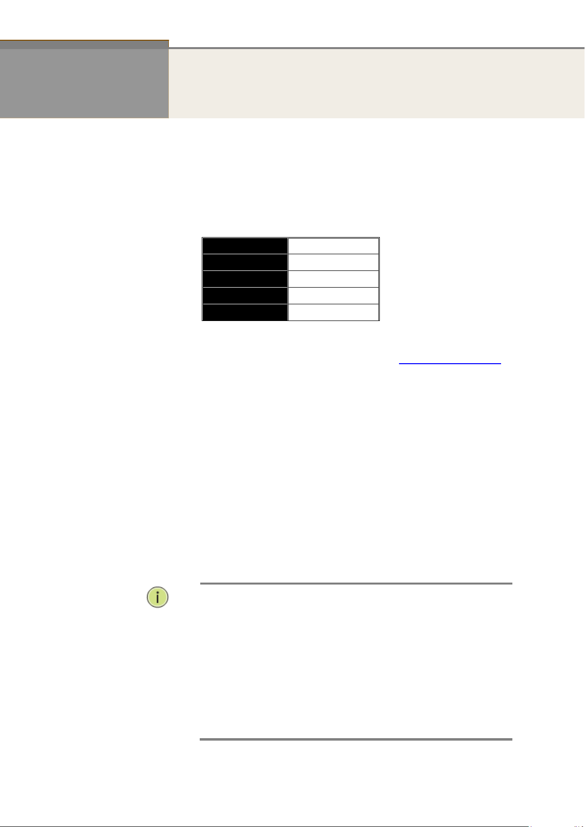
IP Address
192.168.1.1
Subnet Mask
255.255.255.0
Default Gateway
192.168.1.254
Username
admin
Password
NOTE:
When you login the Switch WEB/CLI to manager. You must first
type the Username of the admin. Password was blank, so when
you type after the end Username, please press enter.
Management page to enter WEB/CLI.
When you login GEFXL2-CSW28KX series switch Web UI
management, you can use both ipv4 ipv6 login to manage
To optimize the display effect, we recommend you use Microsoft
IE 6.0 above, Netscape V7.1 above or FireFox V1.00 above and
have the resolution 1024x768. The switch supported neutral web
browser interface
Chapter 1 Operation of Web-based Management
Initial
Configuration
This chapter instructs you how to configure and manage the GEFXL2-
CSW28KX through the web user interface. With this facility, you can
easily access and monitor through any one port of the switch all the status
of the switch, including MIBs status, each port activity, Spanning tree
status, port aggregation status, multicast traffic, VLAN and priority status,
even illegal access record and so on.
The default values of the GEFXL2-CSW28KX are listed in the table below:
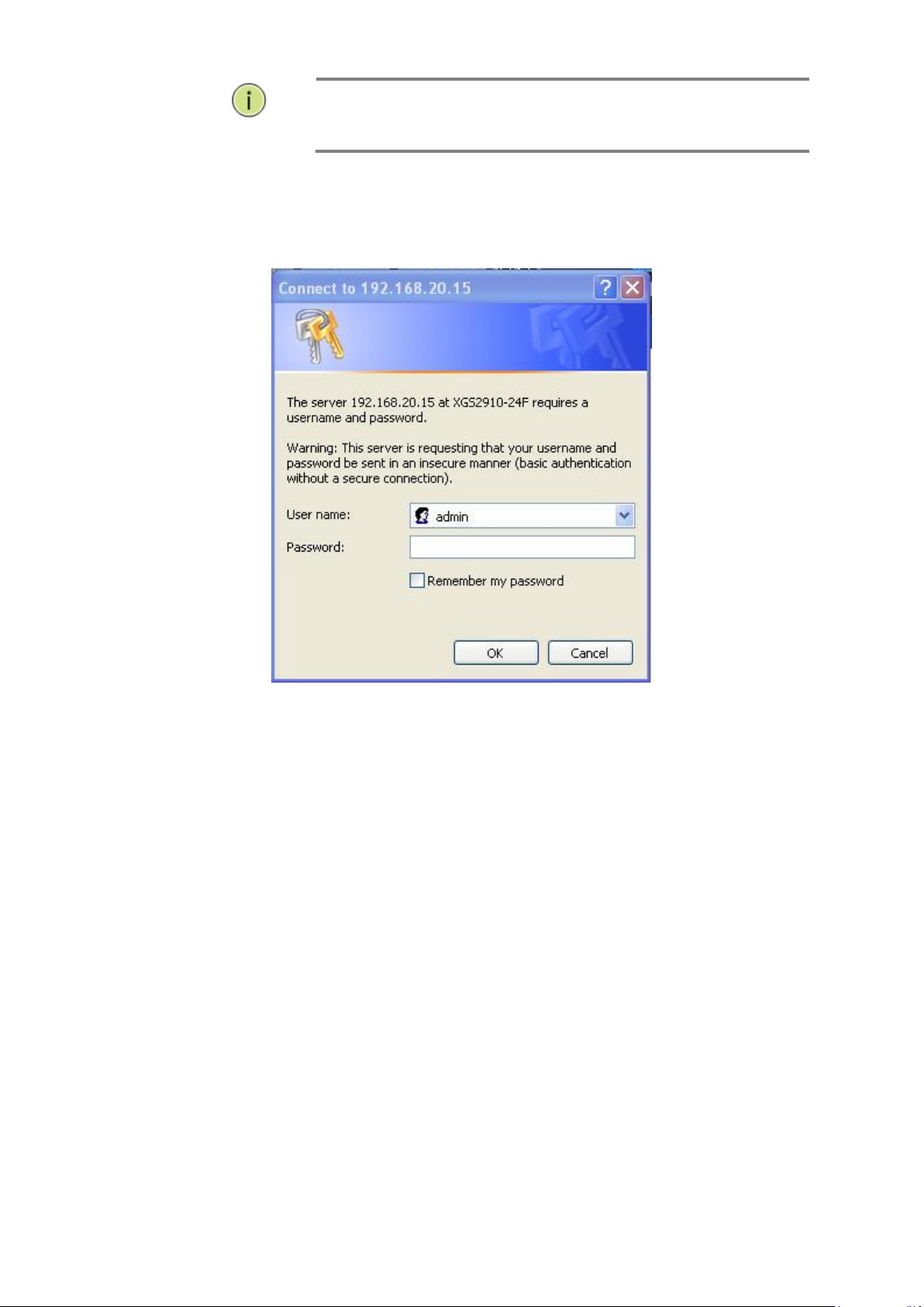
After the GEFXL2-CSW28KX has been finished configuration the it
interface, you can browse it. For instance, type http://192.168.1.1 in
the address row in a browser, it will show the following screen and ask
you inputting username and password in order to login and access
authentication.
The default username is “admin” and password is empty. For the first
time to use, please enter the default username and password, and then
click the <Login> button. The login process now is completed. In this
login menu, you have to input the complete username and password
respectively, the GEFXL2-CSW28KX will not give you a shortcut to
username automatically. This looks inconvenient, but safer.
In the GEFXL2-CSW28KX, it supports a simple user management function
allowing only one administrator to configure the system at the same time.
If there are two or more users using administrator’s identity, it will allow
the only one who logins first to configure the system. The rest of users,
even with administrator’s identity, can only monitor the system. For those
who have no administrator’s identity, can only monitor the system. There
are only a maximum of three users able to login simultaneously in the
GEFXL2-CSW28KX.
Publication date: March, 2012
Revision A1
3
NOTE:
AS GEFXL2-CSW28KX the function enable dhcp, so If you do not
have DHCP server to provide ip addresses to the switch, the
Switch default ip 192.168.1.1
Figure 1 The login page
Publication date: March, 2012
Revision A1
4
Chapter 2 System Configuration
This chapter describes all of the basic configuration tasks which includes the System
Information and any manage of the Switch (e.g. Time, Account, IP, Syslog and SNMP.)
2-1 System Information
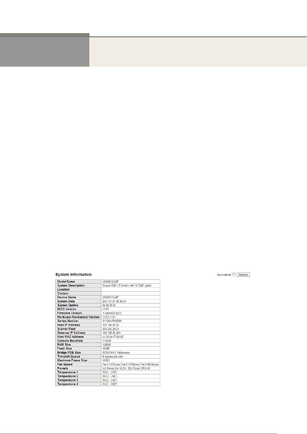
After you login, the switch shows you the system information. This page is default and tells
you the basic information of the system, including “Model Name”, “System Description”,
“Contact”, “Device Name”, “System Up Time”, “BIOS Version”, “Firmware Version”,
“Hardware-Mechanical Version”, “Serial Number”, “Host IP Address”, “Host Mac Address”,
“Device Port”, “RAM Size” , “Flash Size” and. With this information, you will know the software
version used, MAC address, serial number, how many ports good and so on. This is helpful
while malfunctioning.
2-1.1 Information
The switch system information is provided here.
Web interface
To configure System Information in the web interface:
1. Click SYSTEM, System, and Information.
2. Specify the contact information for the system administrator as well as the name and
3. Click Refresh
Figure 2-1.1: System Information
location of the switch. Also indicate the local time zone by configuring the appropriate
offset.
Publication date: March, 2012
Revision A1

5
Publication date: March, 2012
Revision A1

6
Parameter description:
Model name:
The model name of this device.
System description:
As it is, this tells what this device is. Here, it is “8 port 10/100/1000 Base-T
+ 2-Port TP/(100/1G) SFP Combo L2 Plus Managed Switch”.
Location:
Basically, it is the location where this switch is put. User-defined.
Contact:
For easily managing and maintaining device, you may write down the contact
person and phone here for getting help soon. You can configure this parameter
through the device’s user interface or SNMP.
Device name:
The name of the switch. User-defined.
System Date:
Show the system time of the switch. Its format: day of week, month, day,
hours : minutes : seconds, year.
System up time:
The time accumulated since this switch is powered up. Its format is day, hour, minute,
second.
BIOS version:
The version of the BIOS in this switch.
Firmware version:
The firmware version in this switch.
Hardware-Mechanical version:
The version of Hardware and Mechanical. The figure before the hyphen is the version of
electronic hardware; the one after the hyphen is the version of mechanical.
Serial number:
The serial number is assigned by the Manufacture.
Host IP address:
The IP address of the switch.
Host MAC address:
It is the Ethernet MAC address of the management agent in this switch.
Device Port:
Show all types and numbers of the port in the switch.
RAM size:
The size of the RAM in this switch.
Flash size:
The size of the flash memory in this switch.
Bridge FDB size :
To display the bridge FDB size information.
Transmit Queue :
To display the device’s transmit hardware priority queue information.
Publication date: March, 2012
Revision A1

7
Maximum Frame size :
To display the device’s maximum frame size information.
Publication date: March, 2012
Revision A1
8
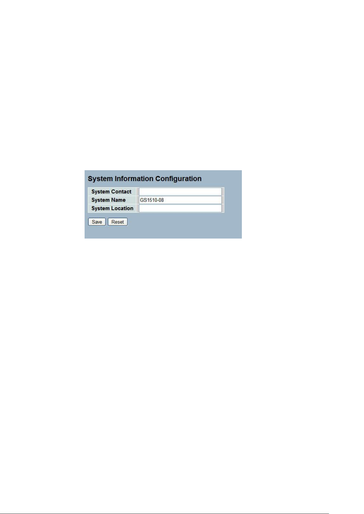
2-1.2 Configuration
You can identify the system by configuring the contact information, name, and location of the
switch.
Web interface
To configure System Information in the web interface:
1. Click System, System Information, Configuration.
2. Write System Contact , System Name, System Location information
in this page.
3. Click Save
Figure 2-1.2: System Information configuration
Parameter description:
System Contact :
The textual identification of the contact person for this managed node, together
with information on how to contact this person. The allowed string length is 0
to 255, and the allowed content is the ASCII characters from 32 to 126.
System Name :
An administratively assigned name for this managed node. By convention, this
is the node's fully-qualified domain name. A domain name is a text string
drawn from the alphabet (A-Za-z), digits (0-9), minus sign (-). No space
characters are permitted as part of a name. The first character must be an
alpha character. And the first or last character must not be a minus sign. The
allowed string length is 0 to 255.
System Location :
The physical location of this node(e.g., telephone closet, 3rd floor). The allowed
string length is 0 to 255, and the allowed content is the ASCII characters from
32 to 126.
Publication date: March, 2012
Revision A1
9
2-2 Time
This page configure the switch Time. Time configure is including Time Configuration and NTP
Configuration
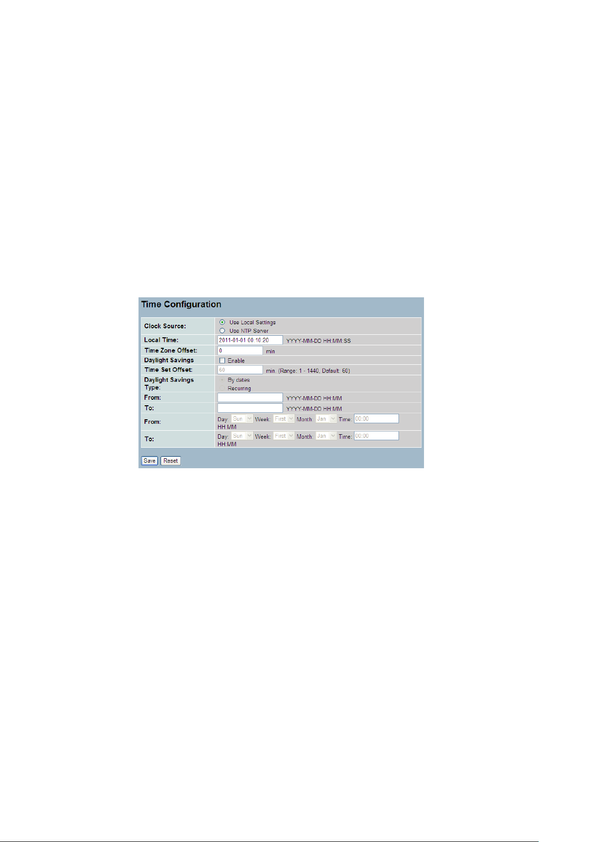
2-2.1 Manual
The switch provides manual and automatic ways to set the system time via NTP. Manual
setting is simple and you just input “Year”, “Month”, “Day”, “Hour”, “Minute” and “Second”
within the valid value range indicated in each item.
Web Interface
To configure Time in the web interface:
1. Click Time , Manual.
2. Specify the Time parameter in manual parameters.
3. Click Save.
Figure 2-2.1: The time configuration
Parameter description:
Clock Source:
To click what clock source for the GEFXL2-CSW28KX. You can select “Use local
Settings” or “Use NTP Server” for GEFXL2-CSW28KX time clock source.
Local Time:
Show the current time of the system.
Time Zone Offset:
Provide the timezone offset relative to UTC/GMT. The offset is given in minutes
east of GMT. The valid range is from -720 to 720 minutes
Daylight Saving:
Daylight saving is adopted in some countries. If set, it will adjust the time lag
or in advance in unit of hours, according to the starting date and the ending
date. For example, if you set the day light saving to be 1 hour. When the time
passes over the starting time, the system time will be increased one hour after
one minute at the time since it passed over. And when the time passes over the
ending time, the system time will be decreased one hour after one minute at
the time since it passed over.
The switch supports valid configurable day light saving time is –5 ~ +5 step
one hour. The zero for this parameter means it need not have to adjust current
time, equivalent to in-act daylight saving. You don’t have to set the
Publication date: Oct., 2011
Revision A1

10
NOTE: The under “from” and “to” was displayed what you set
on the “From” and “To” field information.
starting/ending date as well. If you set daylight saving to be non-zero, you
have to set the starting/ending date as well; otherwise, the daylight saving
function will not be activated.
Time Set Offset:
Provide the Daylight saving time set offset. The offset is given in minutes east
of GMT. The valid range is from 1 to 1440 minutes. default is 60 mins
Daylight Savings Type:
Provide the Daylight savings type selection. You can select “ By Dates” or
“Recurring” two type for Daylight saving type.
From:
To configure when Daylight saving start date and time, the format is “YYYY-MM-
DD HH:MM”.
To:
To configure when Daylight saving end date and time, the format is “YYYY-MM-
DD HH:MM”.
Publication date: March, 2012
Revision A1
11
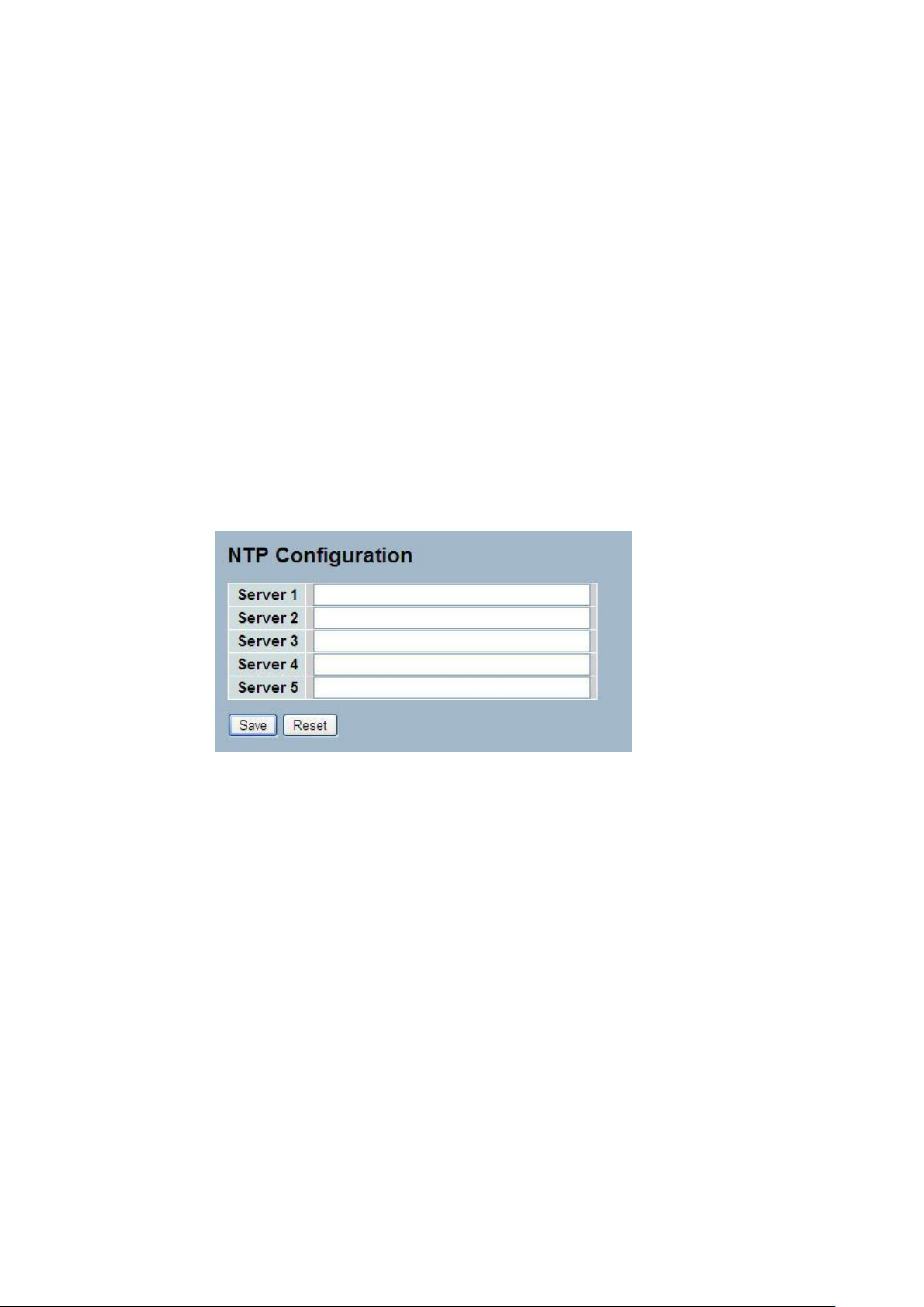
2-2.2 NTP
NTP is Network Time Protocol and is used to sync the network time based Greenwich Mean
Time (GMT). If use the NTP mode and select a built-in NTP time server or manually specify
an user-defined NTP server as well as Time Zone, the switch will sync the time in a short after
pressing <Apply> button. Though it synchronizes the time automatically, NTP does not update
the time periodically without user’s processing.
Time Zone is an offset time off GMT. You have to select the time zone first and then perform
time sync via NTP because the switch will combine this time zone offset and updated NTP
time to come out the local time, otherwise, you will not able to get the correct time. The switch
supports configurable time zone from –12 to +13 step 1 hour.
Default Time zone: +8 Hrs.
Web Interface
To configure Time in the web interface:
1. Click SYSTEM, NTP.
2. Specify the Time parameter in manual parameters.
3. Click Save.
Figure 2-2.2: The NTP configuration
Parameter description:
Server 1to 5 :
Provide the NTP IPv4 or IPv6 address of this switch. IPv6 address is in 128-bit
records represented as eight fields of up to four hexadecimal digits with a colon
separating each field (:). For example, 'fe80::215:c5ff:fe03:4dc7'. The symbol
'::' is a special syntax that can be used as a shorthand way of representing
multiple 16-bit groups of contiguous zeros; but it can only appear once.It can
also represent a legally valid IPv4 address.For example, '::192.1.2.34'.
Buttons
These buttons are displayed on the NTP page:
Save – Click to save changes.
Reset - Click to undo any changes made locally and revert to previously saved
values.
Publication date: Oct., 2011
Revision A1
12
2-3 Account
In this function, only administrator can create, modify or delete the username and password.
Administrator can modify other guest identities’ password without confirming the password but
it is necessary to modify the administrator-equivalent identity. Guest-equivalent identity can
modify his password only. Please note that you must confirm administrator/guest identity in
the field of Authorization in advance before configuring the username and password. Only one
administrator is allowed to exist and unable to be deleted. In addition, up to 4 guest accounts
can be created.
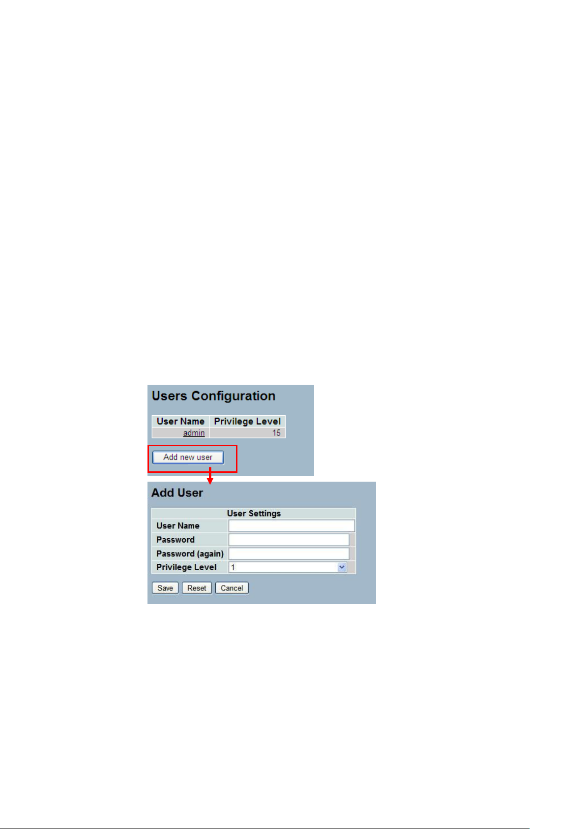
2-3.1 Users
This page provides an overview of the current users. Currently the only way to login as
another user on the web server is to close and reopen the browser
Web Interface
To configure Account in the web interface:
1. Click SYSTEM, Account, Users.
2. Click Add new user
3. Specify the User Name parameter.
4. Click Save.
Figure2- 3.1: The Users Account configuration
Parameter description:
User Name :
The name identifying the user. This is also a link to Add/Edit User.
Password
To type the password. The allowed string length is 0 to 255, and the allowed
content is the ASCII characters from 32 to 126.
Password (again)
To type the password again. You must type the same password again in the
field.
Publication date: Oct., 2011
Revision A1

13
Privilege Level :
The privilege level of the user. The allowed range is 1 to 15. If the privilege
level value is 15, it can access all groups, i.e. that is granted the fully control of
the device. But others value need to refer to each group privilege level. User's
privilege should be same or greater than the group privilege level to have the
access of that group. By default setting, most groups privilege level 5 has the
read-only access and privilege level 10 has the read-write access. And the
system maintenance (software upload, factory defaults and etc.) need user
privilege level 15. Generally, the privilege level 15 can be used for an
administrator account, privilege level 10 for a standard user account and
privilege level 5 for a guest account.
Publication date: March, 2012
Revision A1

14
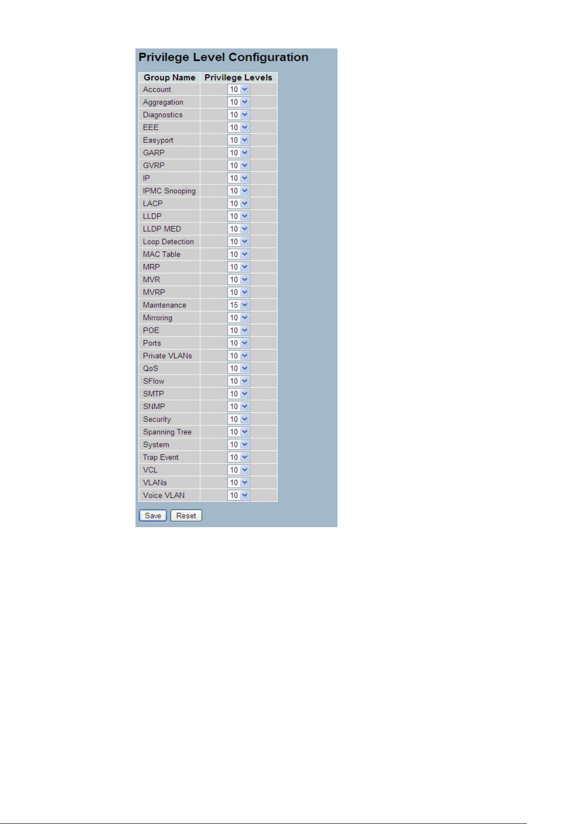
2-3.2 Privitege Level
This page provides an overview of the privilege levels. The switch provides user set Account,
Aggregation,Diagnostics,EEE,GARP,GVRP,IP, IPMC Snooping LACP LLDP LLDP MED MAC
Table MRP MVR MVRP Maintenance Mirroring POE Ports Private VLANs QoS SMTP SNMP
Security Spanning Tree System Trap Event VCL VLANs Voice VLAN Privilege Levels form 1
to 15 .
Web Interface
To configure Privilege Level in the web interface:
1. Click SYSTEM, Account, Privilege Level.
2. Specify the Privilege parameter.
3. Click Save.
Figure2- 3.2: The Privilege Level configuration
Publication date: March, 2012
Revision A1
15
Parameter description:
Group Name
The name identifying the privilege group. In most cases, a privilege level group
consists of a single module (e.g. LACP, RSTP or QoS), but a few of them
contains more than one. The following description defines these privilege level
groups in details:
System: Contact, Name, Location, Timezone, Log.
Security: Authentication, System Access Management, Port (contains Dot1x
port, MAC based and the MAC Address Limit), ACL, HTTPS, SSH, ARP
Inspection and IP source guard.
IP: Everything except 'ping'.
Port: Everything except 'VeriPHY'.
Diagnostics: 'ping' and 'VeriPHY'.
Publication date: March, 2012
Revision A1

16
Maintenance: CLI- System Reboot, System Restore Default, System Password,
Configuration Save, Configuration Load and Firmware Load. Web- Users,
Privilege Levels and everything in Maintenance.
Debug: Only present in CLI.
Privilege Levels
Every group has an authorization Privilege level for the following sub groups:
configuration read-only, configuration/execute read-write, status/statistics
read-only, status/statistics read-write (e.g. for clearing of statistics). User
Privilege should be same or greater than the authorization Privilege level to
have the access to that group.
Publication date: March, 2012
Revision A1
17
2-4 IP
IP is an acronym for Internet Protocol. It is a protocol used for communicating data across an
internet network.
IP is a "best effort" system, which means that no packet of information sent over is assured to
reach its destination in the same condition it was sent. Each device connected to a Local Area
Network (LAN) or Wide Area Network (WAN) is given an Internet Protocol address, and this
IP address is used to identify the device uniquely among all other devices connected to the
extended network.
The current version of the Internet protocol is IPv4, which has 32-bits Internet Protocol
addresses allowing for in excess of four billion unique addresses. This number is reduced
drastically by the practice of webmasters taking addresses in large blocks, the bulk of which
remain unused. There is a rather substantial movement to adopt a new version of the Internet
Protocol, IPv6, which would have 128-bits Internet Protocol addresses. This number can be
represented roughly by a three with thirty-nine zeroes after it. However, IPv4 is still the
protocol of choice for most of the Internet.
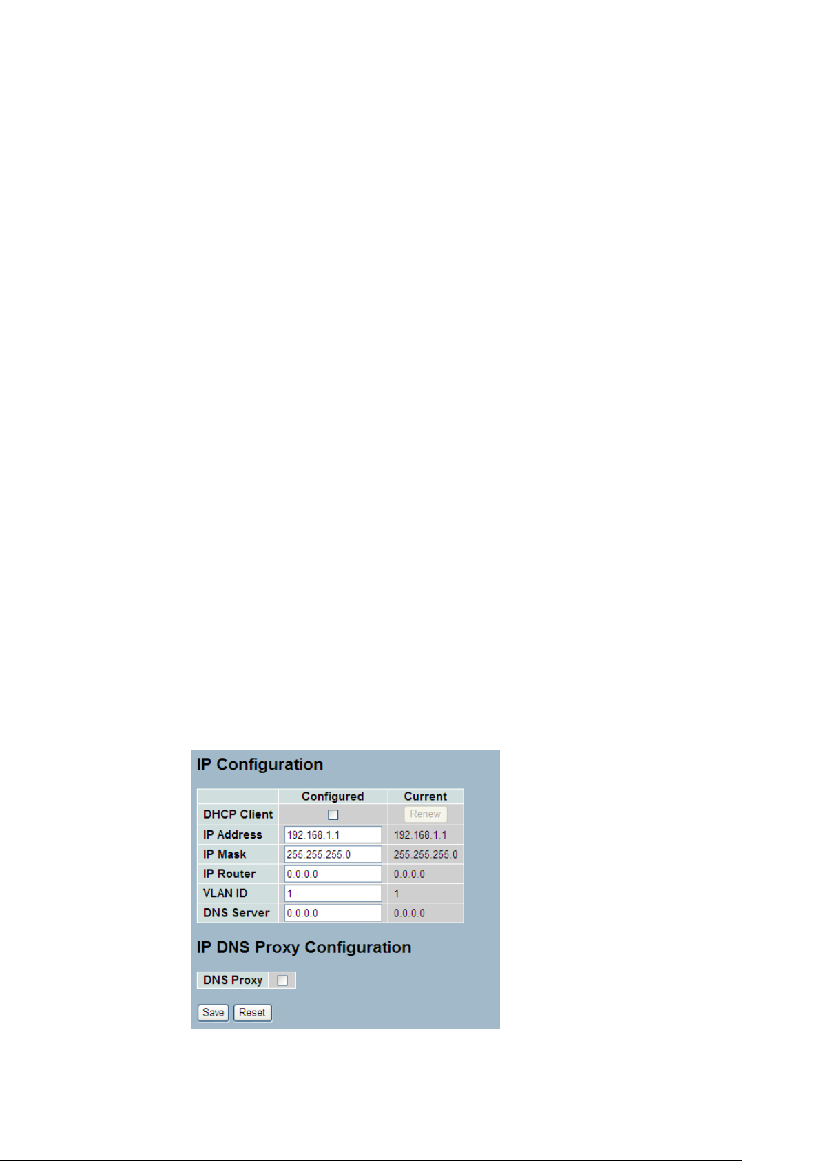
2-4.1 IPV4
The IPv4 address for the switch could be obtained via DHCP Server for VLAN 1. To manually
configure an address, you need to change the switch's default settings to values that are
compatible with your network. You may also need to a establish a default gateway between
the switch and management stations that exist on another network segment.
Configure the switch-managed IP information on this page
The Configured column is used to view or change the IP configuration.
The Current column is used to show the active IP configuration.
Web Interface
To configure an IP address in the web interface:
1. Click System, IP Configuration.
2. Specify the IPv4 settings, and enable DNS proxy service if required.
3. Click Save.
Figure2- 4.1: The IP configuration
Publication date: March, 2012
Revision A1

18
Parameter description:
DHCP Client :
Enable the DHCP client by checking this box. If DHCP fails and the configured
IP address is zero, DHCP will retry. If DHCP fails and the configured IP address
is non-zero, DHCP will stop and the configured IP settings will be used. The
DHCP client will announce the configured System Name as hostname to provide
DNS lookup.
IP Address :
Provide the IP address of this switch in dotted decimal notation.
IP Mask :
Provide the IP mask of this switch dotted decimal notation.
IP Router :
Provide the IP address of the router in dotted decimal notation.
SNTP Server :
Provide the IP address of the SNTP Server in dotted decimal notation.
DNS Server :
Provide the IP address of the DNS Server in dotted decimal notation.
VLAN ID :
Provide the managed VLAN ID. The allowed range is 1 to 4095.
DNS Proxy :
When DNS proxy is enabled, DUT will relay DNS requests to the current
configured DNS server on DUT, and reply as a DNS resolver to the client device
on the network.
Publication date: March, 2012
Revision A1
19
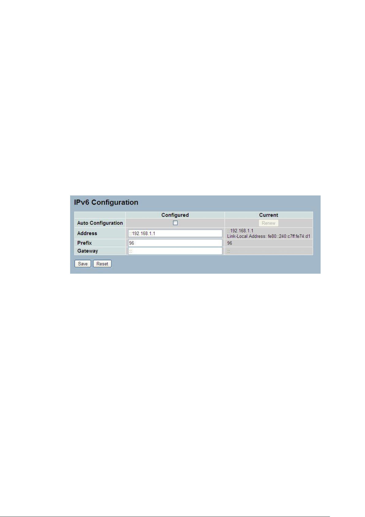
2-4.2 IPV6
This section describes how to configure the switch-managed IPv6 information. The
Configured column is used to view or change the IPv6 configuration. And the Current column
is used to show the active IPv6 configuration.
Configure the switch-managed IPv6 information on this page.
The Configured column is used to view or change the IPv6 configuration.
The Current column is used to show the active IPv6 configuration.
Web Interface
To configure Management IPv6 of the switch in the web interface:
1. Click System, IPv6 Configuration.
2. Specify the IPv6 settings, and enable Auto Configuration service
if required.
3. Click Save.
Figure2- 4.2: The IPv6 configuration
Parameter description:
Auto Configuration :
Enable IPv6 auto-configuration by checking this box. If fails, the configured
IPv6 address is zero. The router may delay responding to a router solicitation
for a few seconds, the total time needed to complete auto-configuration can be
significantly longer.
Address :
Provide the IPv6 address of this switch. IPv6 address is in 128-bit records
represented as eight fields of up to four hexadecimal digits with a colon
separating each field (:). For example, 'fe80::215:c5ff:fe03:4dc7'. The symbol
'::' is a special syntax that can be used as a shorthand way of representing
multiple 16-bit groups of contiguous zeros; but it can only appear once. It can
also represent a legally valid IPv4 address. For example, '::192.1.2.34'.
Prefix :
Provide the IPv6 Prefix of this switch. The allowed range is 1 to 128.
Router
Provide the IPv6 gateway address of this switch. IPv6 address is in 128-bit
records represented as eight fields of up to four hexadecimal digits with a colon
separating each field (:). For example, 'fe80::215:c5ff:fe03:4dc7'. The symbol
'::' is a special syntax that can be used as a shorthand way of representing
multiple 16-bit groups of contiguous zeros; but it can only appear once. It can
Publication date: March, 2012
Revision A1

20
also represent a legally valid IPv4 address. . For example, '::192.1.2.34'.
Publication date: March, 2012
Revision A1
 Loading...