

Manufacture Corporation 94-1518PF User Manual

i
94-1518PF
GUI User Guide
18-Ports Web Smart+ GbE PoE+ Switch
Release A1
2017, Manufacture Corporation. All rights reserved. All brand and product names are trademarks or registered
trademarks of their respective companies

ii
About This Manual
Copyright
Copyright © 2017 Manufacture Technology Corp. All rights reserved.
The products and programs described in this User Guide are licensed products of Manufacture
Technology, This User Guide contains proprietary information protected by copyright, and this User
Guide and all accompanying hardware, software and documentation are copyrighted. No parts of
this User Guide may be copied, photocopied, reproduced, translated or reduced to any electronic
medium or machine-readable from by any means by electronic or mechanical. Including
photocopying, recording, or information storage and retrieval systems, for any purpose other than
the purchaser’s personal use, and without the prior express written permission of Manufacture
Technology.
.
Purpose
This GUI user guide gives specific information on how to operate and use the management
functions of the 94-1518PF via HTTP/HTTPs web browser
Audience
The Manual is intended for use by network administrators who are responsible for operating and
maintaining network equipment; consequently, it assumes a basic working knowledge of general
switch functions, the Internet Protocol (IP), and Hypertext Transfer Protocol (HTTP).
CONVENTIONS
The following conventions are used throughout this manual to show information.
WARRANTY
See the Customer Support/ Warranty booklet included with the product. A copy of the specific
warranty terms applicable to your Manufacture products and replacement parts can be obtained
from your Manufacture Sales and Service Office authorized dealer.
Disclaimer
Manufacture Technology does not warrant that the hardware will work properly in all
environments and applications, and marks no warranty and representation, either implied or
expressed, with respect to the quality, performance, merchantability, or fitness for a particular
purpose. Manufacture disclaims liability for any inaccuracies or omissions that may have occurred.
Information in this User Guide is subject to change without notice and does not represent a
commitment on the part of Manufacture. Manufacture assumes no responsibility for any
inaccuracies that may be contained in this User Guide. Manufacture makes no commitment to
update or keep current the information in this User Guide, and reserves the righter to make
improvements to this User Guide and /or to the products described in this User Guide, at any
time without notice.

iv
Table of Contents
ABOUT THIS MANUAL ................................................................................................................................ II
Revision History ........................................................................................................................................ viii
INTRODUCTION ........................................................................................................................................... 1
CHAPTER 1 OPERATION OF WEB-BASED MANAGEMENT ............................................................ 3
CHAPTER 2 FIRST TIME WIZARD ...................................................................................................... 3
CHAPTER 3 SYSTEM ............................................................................................................................ 6
3-1 SYSTEM INFORMATION ................................................................................................................................... 6
3-2 IP ADDRESS .................................................................................................................................................. 8
3-2.1 IP Settings ........................................................................................................................................... 8
3-2.2 Advanced IP Settings ....................................................................................................................... 10
3-2.3 Status ................................................................................................................................................ 13
3-3 SYSTEM TIME ............................................................................................................................................... 15
3-4 LOG ............................................................................................................................................................ 18
3-4.1 Syslog Configuration ....................................................................................................................... 18
3-4.2 View Log ........................................................................................................................................... 20
3-5 LLDP .......................................................................................................................................................... 22
3-5.1 LLDP Configuration ......................................................................................................................... 22
3-5.2 LLDP-MED Configuration ............................................................................................................... 25
3-5.3 LLDP Neighbour .............................................................................................................................. 32
3-5.4 LLDP-MED Neighbour ..................................................................................................................... 34
3-5.5 LLDP Statistics .................................................................................................................................. 38
3-6 UPNP ......................................................................................................................................................... 40
CHAPTER 4 PORT MANAGEMENT .................................................................................................. 42
4-1 PORT CONFIGURATION ................................................................................................................................. 42
4-2 PORT STATISTICS .......................................................................................................................................... 45
4-3 SFP PORT INFO ........................................................................................................................................... 49
4-4 ENERGY EFFICIENT ETHERNET ....................................................................................................................... 51
4-5 LINK AGGREGATION ..................................................................................................................................... 52
4-5.1 Port ................................................................................................................................................... 52
4-5.2 Aggregator View .............................................................................................................................. 54
4-5.3 Aggregation Hash Mode ................................................................................................................. 56
4-5.4 LACP System Priority ....................................................................................................................... 58
4-6 LOOP PROTECTION ...................................................................................................................................... 59
4-6.1 Configuration ................................................................................................................................... 59
4-6.2 Status ................................................................................................................................................ 61
CHAPTER 5 POE MANAGEMENT ..................................................................................................... 63
5-1 POE CONFIGURATION .................................................................................................................................. 63
5-2 POE STATUS ................................................................................................................................................ 65
5-3 POE POWER DELAY ..................................................................................................................................... 67
5-4 POE AUTO CHECKING .................................................................................................................................. 68
5-5 POE SCHEDULE PROFILE ............................................................................................................................... 70
CHAPTER 6 VLAN MANAGEMENT .................................................................................................. 71
6-1 VLAN CONFIGURATION ............................................................................................................................... 71
6-2 VLAN MEMBERSHIP .................................................................................................................................... 75
6-3 VLAN PORT STATUS .................................................................................................................................... 77
6-4 VLAN SELECTIVE QINQ CONFIGURATION ..................................................................................................... 79
6-5 MAC-BASED VLAN .................................................................................................................................... 81

v
6-5.1 Configuration ................................................................................................................................... 81
6-5.2 Status ................................................................................................................................................ 83
6-6 PROTOCOL-BASED VLAN ............................................................................................................................. 84
6-6.1 Protocol to Group ............................................................................................................................ 84
6-6.2 Group to VLAN ................................................................................................................................ 86
6-7 IP SUBNET-BASED VLAN ............................................................................................................................. 88
6-8 PRIVATE VLAN ............................................................................................................................................ 90
6-9 PORT ISOLATION .......................................................................................................................................... 92
6-10 VOICE VLAN ............................................................................................................................................ 93
6-10.1 Configuration ................................................................................................................................. 93
6-10.2 OUI.................................................................................................................................................. 95
CHAPTER 7 QUALITY OF SERVICE ................................................................................................... 96
7-1 GLOBAL SETTINGS........................................................................................................................................ 96
7-2 PORT SETTINGS ........................................................................................................................................... 98
7-3 PORT POLICING ......................................................................................................................................... 100
7-4 PORT SHAPER ............................................................................................................................................ 101
7-5 STORM CONTROL ...................................................................................................................................... 103
7-6 PORT SCHEDULER ...................................................................................................................................... 105
7-7 COS/802.1P MAPPING ............................................................................................................................. 106
7-8 COS/802.1P REMARKING .......................................................................................................................... 107
7-9 IP PRECEDENCE MAPPING .......................................................................................................................... 108
7-10 IP PRECEDENCE REMARKING .................................................................................................................... 109
7-11 DSCP MAPPING ..................................................................................................................................... 110
7-12 DSCP REMARKING .................................................................................................................................. 111
CHAPTER 8 SPANNING TREE ......................................................................................................... 112
8-1 STATE ........................................................................................................................................................ 112
8-2 REGION CONFIG ........................................................................................................................................ 114
8-3 INSTANCE VIEW ......................................................................................................................................... 115
CHAPTER 9 MAC ADDRESS TABLES ............................................................................................. 122
9-1 CONFIGURATION........................................................................................................................................ 122
9-2 INFORMATION ........................................................................................................................................... 125
CHAPTER 10 MULTICAST ............................................................................................................... 127
10-1 IGMP SNOOPING ................................................................................................................................... 127
10-1.1 Basic Configuration ..................................................................................................................... 127
10-1.2 VLAN Configuration .................................................................................................................... 130
10-1.3 Status ............................................................................................................................................ 132
10-1.4 Group Information ...................................................................................................................... 134
10-1.5 IGMP SFM Information ............................................................................................................... 136
10-2 MLD SNOOPING ..................................................................................................................................... 138
10-2.1 Basic Configuration ..................................................................................................................... 138
10-2.2 VLAN Configuration .................................................................................................................... 141
10-2.3 Status ............................................................................................................................................ 143
10-2.4 Groups Information ..................................................................................................................... 145
10-2.5 MLD SFM Information ................................................................................................................. 147
10-3 MULTICAST FILTERING PROFILE ................................................................................................................. 149
10-3.1 Filtering Profile Table .................................................................................................................. 149
10-3.2 Filtering Address Entry ................................................................................................................ 152
CHAPTER 11 MVR ............................................................................................................................ 154
11-3.1 Basic Configuration ..................................................................................................................... 154
11-3.2 Status ............................................................................................................................................ 157

vi
11-3.3 MVR Groups Information ............................................................................................................ 158
11-3.4 MVR SFM Information ................................................................................................................. 160
CHAPTER 12 DHCP .......................................................................................................................... 162
12-1 SNOOPING .............................................................................................................................................. 162
12-1.1 Configuration ............................................................................................................................... 162
12-1.2 Snooping Table ............................................................................................................................ 164
12-1.3 Detailed Statistics ........................................................................................................................ 166
12-2 RELAY ..................................................................................................................................................... 168
12-2.1 Configuration ............................................................................................................................... 168
12-2.2 Statistics ....................................................................................................................................... 170
12-3 SERVER ................................................................................................................................................... 172
CHAPTER 13 SECURITY ................................................................................................................... 174
13-1 MANAGEMENT ........................................................................................................................................ 174
13-1.1 Account ......................................................................................................................................... 174
13-1.2 Privilege Levels ............................................................................................................................ 176
13-1.3 Auth Method ................................................................................................................................ 178
13-1.4 Access Management .................................................................................................................... 181
13-2 SNMP ................................................................................................................................................... 183
13-2.1 Configuration ............................................................................................................................... 183
13-2.2 SNMPv3 ........................................................................................................................................ 185
13-2.3 Trap Event Severity ...................................................................................................................... 195
13-3 RMON CONFIGURATION ......................................................................................................................... 197
13-3.1 Statistics ....................................................................................................................................... 197
13-3.2 History .......................................................................................................................................... 202
13-3.3 Alarm ............................................................................................................................................ 206
13-3.4 Event ............................................................................................................................................. 211
13-3 IEEE 802.1X ........................................................................................................................................... 215
13-3.1 Configuration ............................................................................................................................... 215
13-3.2 Status ............................................................................................................................................ 219
13-4 IP SOURCE GUARD .................................................................................................................................. 221
13-4.1 Configuration ............................................................................................................................... 221
13-4.2 Static Table ................................................................................................................................... 223
13-4.3 Dynamic Table ............................................................................................................................. 224
13-5 ARP INSPECTION..................................................................................................................................... 226
13-5.1 Configuration ............................................................................................................................... 226
13-5.2 VLAN Configuration .................................................................................................................... 228
13-5.3 Static Table ................................................................................................................................... 229
13-5.4 Dynamic Table ............................................................................................................................. 231
13-6 PORT SECURITY ....................................................................................................................................... 233
13-6.1 Configuration ............................................................................................................................... 233
13-6.2 Status ............................................................................................................................................ 236
13-7 RADIUS ................................................................................................................................................. 238
13-7.1 Configuration ............................................................................................................................... 238
13-7.2 Status ............................................................................................................................................ 241
13-8 TACACS+ .............................................................................................................................................. 246
13-8.1 Configuration ............................................................................................................................... 246
CHAPTER 14 ACCESS CONTROL .................................................................................................... 248
14-1 ACCESS CONTROL LIST ............................................................................................................................. 248
CHAPTER 15 EVENT NOTIFICATION ............................................................................................. 254
15-1 SNMP TRAP ........................................................................................................................................... 254
CHAPTER 16 DIAGNOSTICS ........................................................................................................... 256

vii
16-1 PING ....................................................................................................................................................... 256
16-2 CABLE DIAGNOSTICS ................................................................................................................................ 258
16-3 TRACEROUTE ........................................................................................................................................... 259
16-4 MIRROR .................................................................................................................................................. 260
CHAPTER 17 MAINTENANCE ......................................................................................................... 262
17-1 CONFIGURATION ..................................................................................................................................... 262
17-1.1 Save startup-config ..................................................................................................................... 262
17-1.2 Backup .......................................................................................................................................... 264
17-1.3 Restore .......................................................................................................................................... 265
17-1.4 Activate config ............................................................................................................................. 266
17-1.5 Delete config ................................................................................................................................ 267
17-2 RESTART DEVICE ...................................................................................................................................... 268
17-3 FACTORY DEFAULTS .................................................................................................................................. 269
17-4 FIRMWARE .............................................................................................................................................. 270
17-4.1 Firmware Upgrade ...................................................................................................................... 270
17-4.2 Firmware Selection ...................................................................................................................... 271

viii
Revision History
Release
Date
Revision
Initial Release
2017/01/20
A1

Publication date: Jan., 2017
Revision A1
1
INTRODUCTION
Overview
In this User Guide, it will not only tell you how to install and connect your network system but
configure and monitor the 94-1518PF through the web by (RJ-45) serial interface and Ethernet ports
step-by-step. Many explanations in detail of hardware and software functions are shown as well as the
examples of the operation for web-based interface.
The 94-1518PF are the next generation web smart+ managed switch from Manufacture, is a
portfolio of affordable managed switches that provides a reliable infrastructure for your business
network. These switches deliver more intelligent features you need to improve the availability of your
critical business applications, protect your sensitive information, and optimize your network bandwidth
to deliver information and applications more effectively. It provides the ideal combination of
affordability and capabilities for entry level networking includes small business or enterprise
application and helps you create a more efficient, better-connected workforce.
94-1518PF Web Smart+ Managed Switch provide 18 ports in a single device; the specification
is highlighted as follows.
L2+ features provide better manageability, security, QoS, and performance.
Support IPv4/IPv6 dual stack management
Support SSH/SSL secured management
Support SNMP v1/v2c
Support RMON groups 1,2,3,9
Support sFlow
Support IGMP v1/v2 Snooping
Support MLD v1/v2 Snooping
Support RADIUS and TACACS+ authentication
Support IP Source Guard
Support DHCP Relay (Option 82)
Support DHCP Snooping
Support 802.1d(STP), 802.1w(RSTP) and 802.1s(MSTP)
Support LACP and static link aggregation
Support Q-in-Q double tag VLAN
Support GVRP dynamic VLAN
Overview of this User Guide
Chapter 1 “Operation of Web-based Management”
Chapter 2 “First Time Wizard”
Chapter 3 “System”
Chapter 4 “Port Management”
Chapter 5 “PoE Management”
Chapter 6 “VLAN Management”

2
Chapter 7 “Quality of Service”
Chapter 8 “Spanning tree”
Chapter 9 “MAC Address Tables”
Chapter 10 “Multicast”
Chapter 11 “MVR”
Chapter 12 “DHCP”
Chapter 13 “Security”
Chapter 14 “Access Control”
Chapter 15 “Event Notification”
Chapter 16 “Diagnostics”
Chapter 17 “Maintenance”

Publication date: Jan., 2017
Revision A1
3
Chapter 1 Operation of Web-based Management
Initial
Configuration
This chapter instructs you how to configure and manage the 94-1518PF through the
web user interface. With this facility, you can easily access and monitor through any
one port of the switch all the status of the switch, including MIBs status, each port
activity, Spanning tree status, port aggregation status, multicast traffic, VLAN and
priority status, even illegal access record and so on.
The default values of the 94-1518PF are listed in the table below:
IP Address
192.168.1.1
Subnet Mask
255.255.255.0
Default Gateway
192.168.1.254
Username
admin
Password
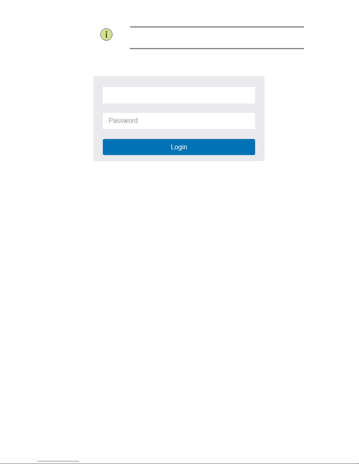
After the 94-1518PF has been finished configuration it interface, you can browse it. For
instance, type http://192.168.1.1 in the address row in a browser, it will show the
following screen and ask you inputting username and password in order to login and
access authentication.
The default username is “admin” and password is empty. For the first time to use,
please enter the default username and password, and then click the <Login> button.
The login process now is completed. In this login menu, you have to input the complete
username and password respectively, the 94-1518PF will not give you a shortcut to
username automatically. This looks inconvenient, but safer.
In the 94-1518PF, allowed two or more users using administrator’s identity to manage
this switch, which administrator to do the last setting, it will be an available
configuration to effect the system.
NOTE:
When you login the Switch WEB page to manage. You must first type the
Username of the admin. Password was blank, so when you type after the
end Username, please press enter. Management page to enter WEB.
When you login 94-1518PF series switch Web UI management, you can use
both ipv4 ipv6 login to manage
To optimize the display effect, we recommend you use Microsoft IE 6.0
above, Netscape V7.1 above or Firefox V1.00 above and have the resolution
1024x768. The switch supported neutral web browser interface
NOTE:
AS 94-1518PF the function enable dhcp, so If you do not have DHCP server
to provide ip addresses to the switch, the Switch default ip 192.168.1.1
Figure 1: The login page
3
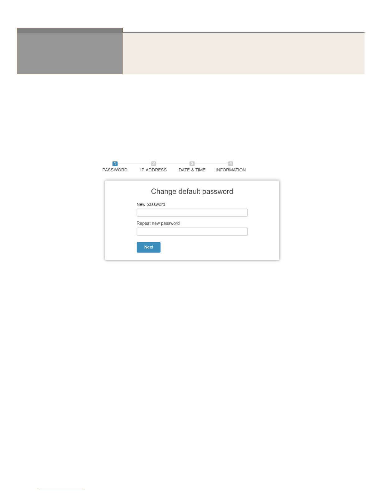
Chapter 2 First Time Wizard
The first time you use this device you can configure some basic settings, such as password, IP
address, date & time, system information.
According to the following procedure:
Step1: Change default password
Configure new password and enter it again.
Figure 2: Change default password
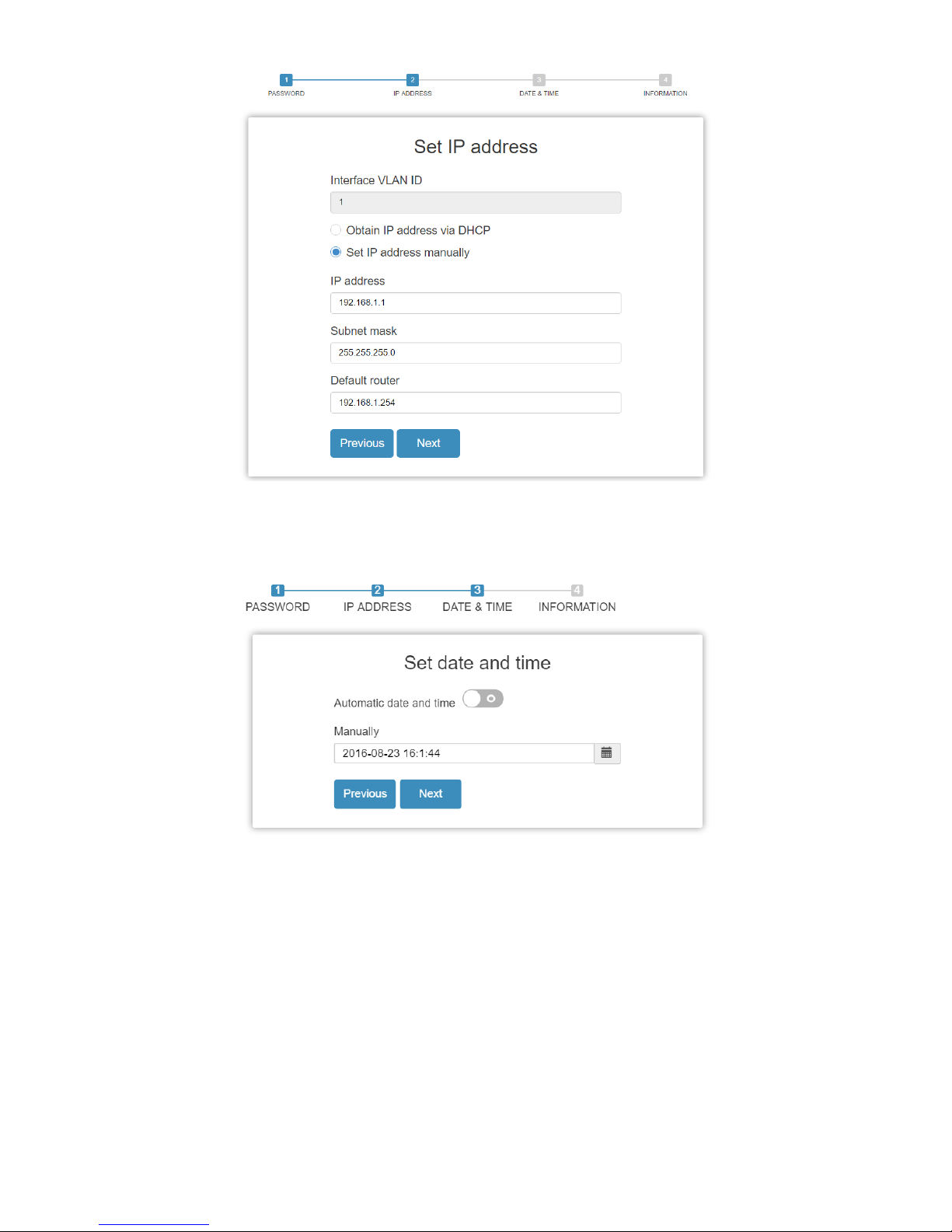
Step2: Set IP address
Select “obtain IP address via DHCP” or “Set IP address manually” to set IP address.
4
Figure 2: Set IP address
Step3: Set date and time
Enable “Automatic data and time” or select manually to set date and time.
Figure 2: Set date and time
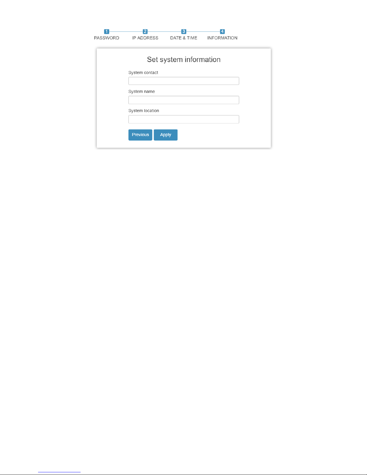
Step4: Set system information
You can set some system information to this device, such as “System contact”, “System name”,
“System location”.
5
Figure 2: Set system information
6
Chapter 3 System
This chapter describes the entire basic configuration tasks which includes the System
Information and any manage of the Switch (e.g. Time, Account, IP, Syslog and NTP.)
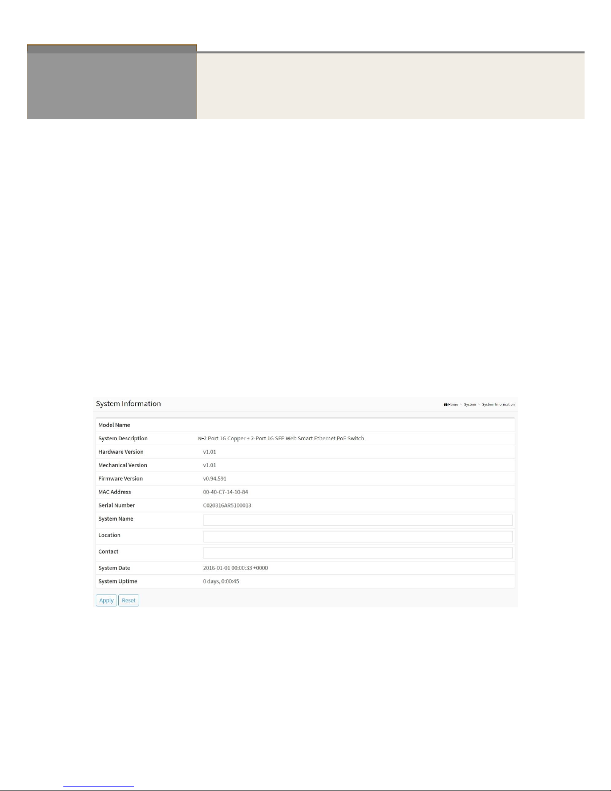
3-1 System Information
You can identify the system by configuring system name, location and the contact of the switch.
The switch system’s contact information is provided here.
Web interface
To configure System Information in the web interface:
1. Click System and System Information.
2. Write System Name, Location, Contact information in this page.
3. Click Apply
Figure 3-1: System Information
Parameter description:
Model Name
Displays the factory defined model name for identification purpose.
System Description
Displays the system description.

7
Hardware-Mechanical Version
The hardware and mechanical version of this switch.
Firmware Version
The software version of this switch.
MAC Address
The MAC Address of this switch.
Series Number
The serial number of this switch.
System name :
An administratively assigned name for this managed node. By convention, this is the node's
fully-qualified domain name. A domain name is a text string drawn from the alphabet (A-Z,
a-z), digits (0-9), minus sign (-). No space characters are permitted as part of a name. The
first character must be an alpha character. And the first or last character must not be a
minus sign. The allowed string length is 0 to 128.
Location :
The physical location of this node(e.g., telephone closet, 3rd floor). The allowed string
length is 0 to 128, and the allowed content is the ASCII characters from 32 to 1.
Contact :
The textual identification of the contact person for this managed node, together with
information on how to contact this person. The allowed string length is 0 to 128, and the
allowed content is the ASCII characters from 32 to 126.
System Date
The current (GMT) system time and date. The system time is obtained through the Timing
server running on the switch, if any.
System Uptime
The period of time the device has been operational.
8
3-2 IP Address
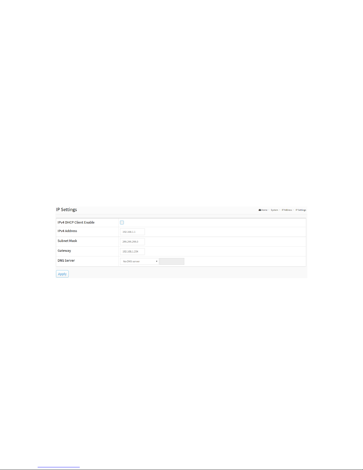
3-2.1 IP Settings
The IPv4 address for the switch could be obtained via DHCP Server for VLAN 1. To manually
configure an address, you need to change the switch's default settings to values that are
compatible with your network. You may also need to establish a default gateway between the
switch and management stations that exist on another network segment.
Configure the IP basic settings
Web Interface
To configure an IP Settings in the web interface:
1. Click System, IP Address and IP Settings.
2. Enable or Disable the IPv4 DHCP Client.
3. Specify the IPv4 Address, Subnet Mask, Gateway.
4. Select DNS Server.
5. Click Apply
Figure 3-2.1: The IP settings
Parameter description:
IPv4 DHCP Client Enable :
Enable the DHCP client by checking this box. If this option is enabled, the system will
configure the IPv4 address and mask of the interface using the DHCP protocol. The DHCP
client will announce the configured System Name as hostname to provide DNS lookup.
IPv4 Address :
The IPv4 address of the interface in dotted decimal notation.
If DHCP is enabled, this field is not used. The field may also be left blank if IPv4 operation
on the interface is not desired.
Subnet Mask :
User IP subnet mask of the entry.
Gateway :
The IP address of the IP gateway. Valid format is dotted decimal notationor a valid IPv6
notation. Gateway and Network must be of the same type.

9
DNS Server :
This setting controls the DNS name resolution done by the switch. The following modes are
supported:
No DNS server
No DNS server will be used.
Configured
Explicitly provide the IP address of the DNS Server in dotted decimal notation.
From this DHCP interface
Specify from which DHCP-enabled interface a provided DNS server should be
preferred.
From any DHCP interfaces
The first DNS server offered from a DHCP lease to a DHCP-enabled interface will be
used.
Buttons
Apply :
Click to save changes.
10
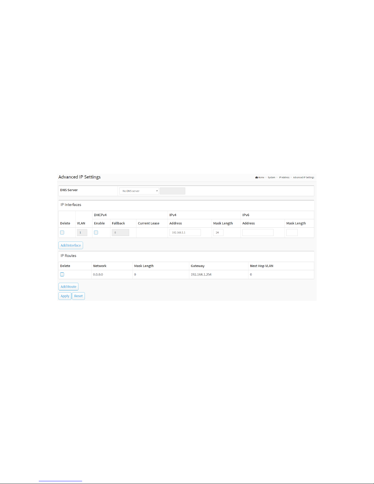
3-2.2 Advanced IP Settings
Configure the switch-managed IP information on this page
Configure IP basic settings, control IP interfaces and IP routes.
The maximum number of interfaces supported is 8 and the maximum number of routes is 8.
Web Interface
To configure an Advanced IP Settings in the web interface:
1. Click System, IP Address and Advanced IP Settings.
2. Click Add Interface then you can create new Interface on the switch.
3. Click Add Route then you can create new Route on the switch
4. Click Apply
Figure 3-2.2: The advanced IP settings
Parameter description:
IP Configuration
DNS Server :
This setting controls the DNS name resolution done by the switch. The following modes are
supported:
No DNS server
No DNS server will be used.
Configured
Explicitly provide the IP address of the DNS Server in dotted decimal notation.
From this DHCP interface
Specify from which DHCP-enabled interface a provided DNS server should be
preferred.
From any DHCP interfaces
The first DNS server offered from a DHCP lease to a DHCP-enabled interface will be
used.

11
IP Interfaces
Delete :
Select this option to delete an existing IP interface.
VLAN :
The VLAN associated with the IP interface. Only ports in this VLAN will be able to access the
IP interface. This field is only available for input when creating an new interface.
IPv4 DHCP Enabled :
Enable the DHCP client by checking this box. If this option is enabled, the system will
configure the IPv4 address and mask of the interface using the DHCP protocol. The DHCP
client will announce the configured System Name as hostname to provide DNS lookup.
IPv4 DHCP Fallback Timeout :
The number of seconds for trying to obtain a DHCP lease. After this period expires, a
configured IPv4 address will be used as IPv4 interface address. A value of zero disables the
fallback mechanism, such that DHCP will keep retrying until a valid lease is obtained. Legal
values are 0 to 4294967295 seconds.
IPv4 DHCP Current Lease :
For DHCP interfaces with an active lease, this column show the current interface address, as
provided by the DHCP server.
IPv4 Address :
The IPv4 address of the interface in dotted decimal notation.
If DHCP is enabled, this field is not used. The field may also be left blank if IPv4 operation
on the interface is not desired.
IPv4 Mask :
The IPv4 network mask, in number of bits (prefix length). Valid values are between 0 and
30 bits for a IPv4 address.
If DHCP is enabled, this field is not used. The field may also be left blank if IPv4 operation
on the interface is not desired.
IPv6 Address :
The IPv6 address of the interface. A IPv6 address is in 128-bit records represented as eight
fields of up to four hexadecimal digits with a colon separating each field (:). For example,
fe80::215:c5ff:fe03:4dc7. The symbol :: is a special syntax that can be used as a shorthand
way of representing multiple 16-bit groups of contiguous zeros; but it can appear only
once. It can also represent a legally valid IPv4 address. For example, ::192.1.2.34.
The field may be left blank if IPv6 operation on the interface is not desired.
IPv6 Mask :
The IPv6 network mask, in number of bits (prefix length). Valid values are between 1 and
128 bits for a IPv6 address.
The field may be left blank if IPv6 operation on the interface is not desired.
IP Routes
Delete :
Select this option to delete an existing IP route.
Network :
The destination IP network or host address of this route. Valid format is dotted decimal
notation or a valid IPv6 notation. A default route can use the value 0.0.0.0 or IPv6 ::
notation.

12
Mask Length :
The destination IP network or host mask, in number of bits (prefix length). It defines how
much of a network address that must match, in order to qualify for this route. Valid values
are between 0 and 32 bits respectively 128 for IPv6 routes. Only a default route will have a
mask length of 0 (as it will match anything).
Gateway :
The IP address of the IP gateway. Valid format is dotted decimal notation or a valid IPv6
notation. Gateway and Network must be of the same type.
Next Hop VLAN (Only for IPv6) :
The VLAN ID (VID) of the specific IPv6 interface associated with the gateway.
The given VID ranges from 1 to 4094 and will be effective only when the corresponding
IPv6 interface is valid.
If the IPv6 gateway address is link-local, it must specify the next hop VLAN for the gateway.
If the IPv6 gateway address is not link-local, system ignores the next hop VLAN for the
gateway.
Buttons
Add Interface :
Click to add a new IP interface. A maximum of 8 interfaces is supported.
Add Route :
Click to add a new IP route. A maximum of 8 routes is supported.
Apply :
Click to save changes.
Reset :
Click to undo any changes made locally and revert to previously saved values.

13
3-2.3 Status
This page displays the status of the IP protocol layer. The status is defined by the IP
interfaces, the IP routes and the neighbour cache (ARP cache) status.
Web Interface
To display the log configuration in the web interface:
1. Click System, IP Address and Status.
2. Display the IP Configuration information.
Figure 3-2.3: The IP Status
Parameter description:
IP Interfaces
Interface :

14
Show the name of the interface.
Type :
Show the address type of the entry. This may be LINK or IPv4.
Address :
Show the current address of the interface (of the given type).
Status :
Show the status flags of the interface (and/or address).
IP Routes
Network :
Show the destination IP network or host address of this route.
Gateway :
Show the gateway address of this route.
Status :
Show the status flags of the route.
Interface:
Show the name of the interface.
Neighbour cache
IP Address :
Show the IP address of the entry.
Link Address :
Show the Link (MAC) address for which a binding to the IP address given exist.
DNS Server
Type :
Show the address type of the entry. This may be LINK or IPv4.
IP Address :
Show the current address of the interface (of the given type).
Interface :
Show the name of the interface.
Buttons
Figure 3-2.3: The IP Status buttons
Auto-refresh :
Check this box to refresh the page automatically. Automatic refresh occurs every 3 seconds.
Refresh :
Click to refresh the page immediately.
15
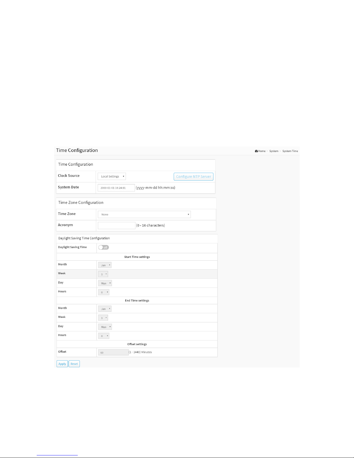
3-3 System Time
The switch provides manual and automatic ways to set the system time via NTP. Manual
setting is simple and you just input “Year”, “Month”, “Day”, “Hour” and “Minute” within the
valid value range indicated in each item.
Web Interface
To configure Time in the web interface:
1. Click System and System Time
2. Specify the Time parameter.
3. Click Apply.
Figure 3-3: The time configuration
Parameter description:
Time Configuration
Clock Source :
There are two modes for configuring how the Clock Source from. Select "Local Settings" :
Clock Source from Local Time. Select "NTP Server" : Clock Source from NTP Server.

16
System Date :
Show the current time of the system. The year of system date limits between 2000 and 2037.
Time Zone Configuration
Time Zone :
Lists various Time Zones worldwide. Select appropriate Time Zone from the drop down and
click Apply to set.
Acronym :
User can set the acronym of the time zone. This is a User configurable acronym to identify
the time zone. (Range: Up to 16 characters)
Daylight Saving Time Configuration
Daylight Saving Time :
This is used to set the clock forward or backward according to the configurations set below
for a defined Daylight Saving Time duration. Select 'Disable' to disable the Daylight Saving
Time configuration. Select 'Recurring' and configure the Daylight Saving Time duration to
repeat the configuration every year. Select 'Non-Recurring' and configure the Daylight
Saving Time duration for single time configuration. (Default: Disabled).
Recurring Configuration
Start time settings :
Week - Select the starting week number.
Day - Select the starting day.
Month - Select the starting month.
Hours - Select the starting hour.
End time settings :
Week - Select the ending week number.
Day - Select the ending day.
Month - Select the ending month.
Hours - Select the ending hour.
Offset settings :
Offset - Enter the number of minutes to add during Daylight Saving Time. (Range: 1 to
1440)
NOTE: The under “Start Time Settings” and “End Time Settings” was
displayed what you set on the “Start Time Settings” and “End Time
Settings” field information.
Buttons
Apply :
Click to save changes.
Reset :
Click to undo any changes made locally and revert to previously saved values.
Figure 3-3: The Configure NTP Server button
17
Configure NTP Server :
Click to configure NTP server, When Clock Source select from NTP Server.
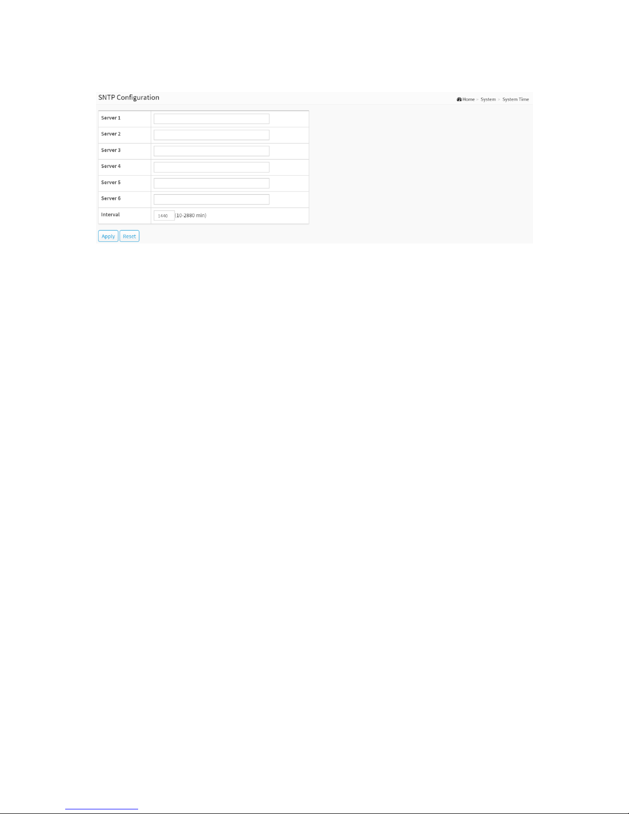
Figure 3-3: The SNTP configuration
NTP is Network Time Protocol and is used to sync the network time based Greenwich Mean
Time (GMT). If use the NTP mode and select a built-in NTP time server or manually specify an
user-defined NTP server as well as Time Zone, the switch will sync the time in a short after
pressing <Apply> button. Though it synchronizes the time automatically, NTP does not update
the time periodically without user’s processing.
Time Zone is an offset time of GMT. You have to select the time zone first and then perform
time sync via NTP because the switch will combine this time zone offset and updated NTP time
to come out the local time, otherwise, you will not able to get the correct time. The switch
supports configurable time zone from –12 to +13 step 1 hour.
Default Time zone: +8 Hrs.
Parameter description :
Server 1 to 6:
Provide the NTP IPv4 or IPv6 address of this switch. IPv6 address is in 128-bit records
represented as eight fields of up to four hexadecimal digits with a colon separating each field
(:). For example, 'fe80::215:c5ff:fe03:4dc7'. The symbol '::' is a special syntax that can be used
as a shorthand way of representing multiple 16-bit groups of contiguous zeros; but it can
only appear once. It can also represent a legally valid IPv4 address. For example, '::192.1.2.34'.
Interval
You can specify the time interval in seconds after which a time check and, in case of deviation,
a resynchronization of the internal device clock against the specified timeserver via Network
Time Protocol(NTP) should be performed.
Buttons
These buttons are displayed on the SNTP page:
Apply :
Click to save changes.
Reset :
Click to undo any changes made locally and revert to previously saved values.
18
3-4 Log
3-4.1 Syslog Configuration
The Syslog Configuration is a standard for logging program messages . It allows separation of
the software that generates messages from the system that stores them and the software that
reports and analyzes them. It can be used as well a generalized informational, analysis and
debugging messages. It is supported by a wide variety of devices and receivers across multiple
platforms.
Web Interface
To configure Syslog Configuration in the web interface:
1. Click System, Log and Syslog Configuration.
2. Specify the syslog parameters include IP Address of Syslog server and Port number.
3. Evoke the Syslog to enable it.
4. Click Apply.
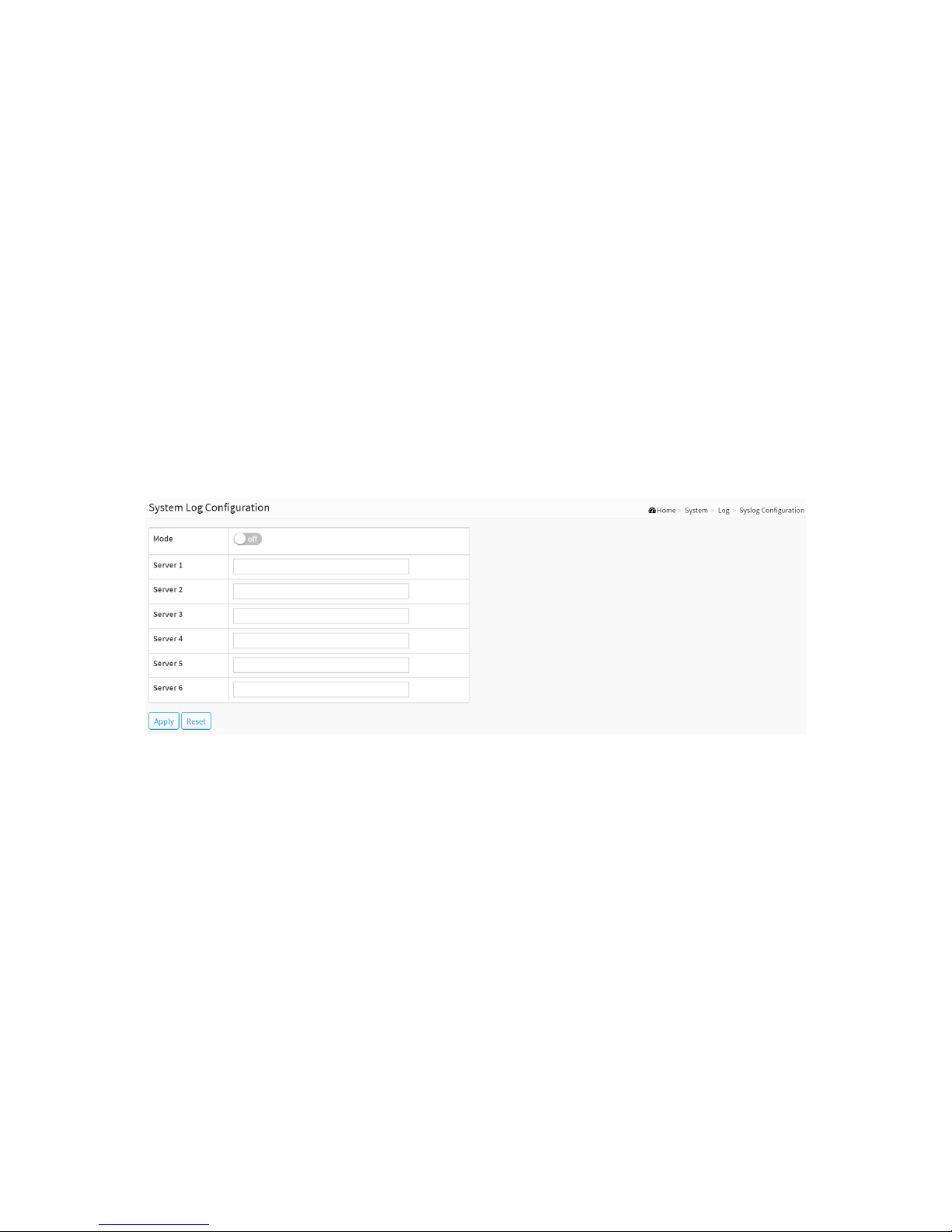
Figure 3-4.1: The System Log configuration
Parameter description:
Mode :
Indicate the server mode operation. When the mode operation is enabled, the syslog
message will send out to syslog server. The syslog protocol is based on UDP communication
and received on UDP port 514 and the syslog server will not send acknowledgments back
sender since UDP is a connectionless protocol and it does not provide acknowledgments.
The syslog packet will always send out even if the syslog server does not exist. Possible modes
are:
On: Enable server mode operation.
Off: Disable server mode operation.
Server 1 to 6 :
Indicates the IPv4 hosts address of syslog server. If the switch provide DNS feature, it also
can be a host name.
Buttons
Apply :

19
Click to save changes.
Reset :
Click to undo any changes made locally and revert to previously saved values.
20
3-4.2 View Log
This section describes that display the system log information of the switch
Web Interface
To display the log Information in the web interface:
1. Click System, Log and View Log.
2. Display the log information.
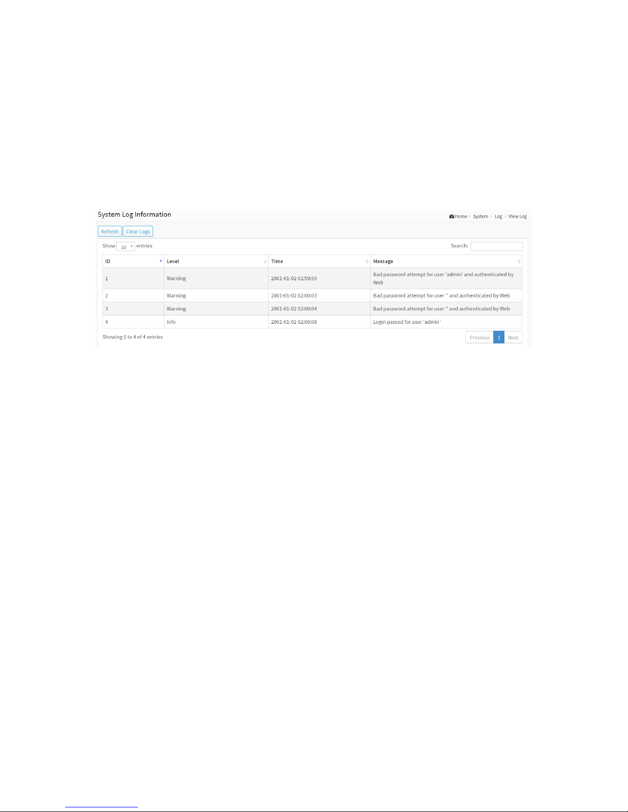
Figure 3-4.2: The System Log Information
Parameter description:
ID :
ID (>= 1) of the system log entry.
Level :
level of the system log entry. The following level types are supported:
Debug : debug level message.
Info : informational message.
Notice : normal, but significant, condition.
Warning : warning condition.
Error : error condition.
Crit : critical condition.
Alert : action must be taken immediately.
Emerg : system is unusable.
Time :
It will display the log record by device time. The time of the system log entry.
Message :
It will display the log detail message. The message of the system log entry.
Search :
You can search for the information that you want to see.
Show entries :

21
You can choose how many items you want to show.
Buttons
Refresh :
Updates the system log entries, starting from the current entry ID.
Clear Logs :
Clear all the system log entries.
Next :
Updates the system log entries, turn to the next page.
Previous :
Updates the system log entries, turn to the previous page.
 Loading...