

Page 1

X24 ATEX/IECEx Telemetry User Manual
mantracourt.com
X24
Wireless ATEX/IECEx Telemetry
This user manual should be used in conjunction with the T24 Telemetry User Manual
MICRON METERS
www.micronmeters.com
metersinfo@micronmeters.com
Page 2

Mantracourt Electronics Limited T24 Telemetry User Manual
1
Introduction / Overview .............................................................................................................................................4
Navigating This Manual .............................................................................................................................................4
Product Quick Locator ................................................................................................................................................4
X24 and T24 Telemetry Basic Principles ..................................................................................................................5
Transmitters & Receivers ......................................................................................................................................................................... 5
Transmitters .............................................................................................................................................................................................. 5
Receivers .................................................................................................................................................................................................... 5
Radio Channel and Group Key .............................................................................................................................................................. 5
Radio Channel ......................................................................................................................................................................................... 5
Group Key .................................................................................................................................................................................................. 5
Configuring Multiple Modules to Use the Same Radio Settings ............................................................................................. 6
ID and Data Tags ......................................................................................................................................................................................... 6
Transmitter Module Modes of Operation ......................................................................................................................................... 6
Operational (Low Power Mode) ....................................................................................................................................................... 6
Operational (Non Low Power Mode) ............................................................................................................................................. 6
Configuration ........................................................................................................................................................................................... 6
Sleep ............................................................................................................................................................................................................ 6
Transmitter Module Sleep Delay Settings ......................................................................................................................................... 7
Pairing ............................................................................................................................................................................................................. 7
Pairing From T24 Toolkit ..................................................................................................................................................................... 7
Pairing From a Receiver Module ...................................................................................................................................................... 7
Soft Pairing .................................................................................................................................................................................................... 8
Configuring an Attached Base Station ............................................................................................................................................... 8
Asynchronous Operation and Logging .............................................................................................................................................. 8
Bandwidth ...................................................................................................................................................................................................... 9
Repeaters and Repeater Subgroups ................................................................................................................................................... 9
T24 Toolkit ................................................................................................................................................................ 10
Common Toolkit Pages ........................................................................................................................................... 11
Setup Base Station Communications ............................................................................................................................................... 11
Analyser ....................................................................................................................................................................................................... 12
Channel Monitor ...................................................................................................................................................................................... 13
Home ............................................................................................................................................................................................................ 15
Connecting to a remote module ................................................................................................................................................... 15
Connecting to the attached base station module ................................................................................................................. 16
Manual Connection ............................................................................................................................................................................ 16
Information ................................................................................................................................................................................................. 17
Battery and Radio Levels ....................................................................................................................................................................... 18
Battery and Radio Levels Advanced ................................................................................................................................................. 19
Radio Settings ........................................................................................................................................................................................... 20
Radio Settings Advanced ...................................................................................................................................................................... 21
Save and Restore ..................................................................................................................................................................................... 22
Transmitter Modules ............................................................................................................................................... 23
X24-ACMi-SA, X24-SAe, X24-SAi....................................................................................................................................................... 23
Overview ................................................................................................................................................................................................. 23
Order Codes .......................................................................................................................................................................................... 23
X24-SAe .............................................................................................................................................................................................. 23
T24-ACMi-SA .................................................................................................................................................................................... 23
Connections ........................................................................................................................................................................................... 24
X24-SAe, X24-SAi ............................................................................................................................................................................ 24
Power .............................................................................................................................................................................................. 24
Sensor ............................................................................................................................................................................................. 24
X24-ACMi-SA ................................................................................................................................................................................... 25
Power .............................................................................................................................................................................................. 25
Sensor ............................................................................................................................................................................................. 25
Configuration ........................................................................................................................................................................................ 26
Data Rates and Quality ................................................................................................................................................................. 26
Page 3

Mantracourt Electronics Limited T24 Telemetry User Manual
2
Calibration ......................................................................................................................................................................................... 28
Calibration by Certificate ............................................................................................................................................................. 30
Calibration Advanced .................................................................................................................................................................... 31
Advanced Settings.......................................................................................................................................................................... 32
Enclosure & Mounting ...................................................................................................................................................................... 33
X24-SAe, X24-SAi ............................................................................................................................................................................ 33
X24-ACMi-SA ................................................................................................................................................................................... 33
Antennas ................................................................................................................................................................................................. 33
X24-SAe .............................................................................................................................................................................................. 33
X24-ACMi-SA ................................................................................................................................................................................... 33
Specification .......................................................................................................................................................................................... 34
Radio Range ...................................................................................................................................................................................... 34
Receiver Modules ..................................................................................................................................................... 35
X24-HD......................................................................................................................................................................................................... 35
Overview ................................................................................................................................................................................................. 35
Order Codes .......................................................................................................................................................................................... 35
X24-HD ........................................................................................................................................................................................... 35
Connections ........................................................................................................................................................................................... 35
Power .............................................................................................................................................................................................. 35
Quick Start.............................................................................................................................................................................................. 36
Connecting Power .......................................................................................................................................................................... 36
X24-HD ........................................................................................................................................................................................... 36
Transmitter Module .................................................................................................................................................................. 36
Viewing Transmitter Data ............................................................................................................................................................ 36
Operation ........................................................................................................................................................................................... 37
Keys ................................................................................................................................................................................................. 37
Indicators ....................................................................................................................................................................................... 37
Errors ............................................................................................................................................................................................... 38
Configuration ........................................................................................................................................................................................ 39
Modes of Operation ...................................................................................................................................................................... 39
No List Entered (Default) ......................................................................................................................................................... 39
List Entered ................................................................................................................................................................................... 39
List Entered Plus Summing Groups .................................................................................................................................... 39
Global Settings ................................................................................................................................................................................ 40
Configure Inputs ............................................................................................................................................................................. 42
No Defined Transmitters ......................................................................................................................................................... 42
Defined Transmitters ................................................................................................................................................................ 44
General Tab .............................................................................................................................................................................. 44
Zero Tab .................................................................................................................................................................................... 46
Scaling Tab ............................................................................................................................................................................... 48
Group Membership Tab...................................................................................................................................................... 49
Summing Groups ....................................................................................................................................................................... 50
General Tab .............................................................................................................................................................................. 50
Zero Tab .................................................................................................................................................................................... 52
Scaling Tab ............................................................................................................................................................................... 54
Members Tab .......................................................................................................................................................................... 56
Example Configuration Scenarios ............................................................................................................................................ 57
Examples Using No Defined Transmitter List (Roaming Mode) .............................................................................. 57
Long Bridge ............................................................................................................................................................................. 57
Brewery ...................................................................................................................................................................................... 57
Example of Defined Transmitter List .................................................................................................................................. 57
Single Transmitter ................................................................................................................................................................. 57
Multiple Transmitters ........................................................................................................................................................... 57
Example of Summing Groups ............................................................................................................................................... 57
Alternative Units .................................................................................................................................................................... 57
Grouping Sums....................................................................................................................................................................... 58
Page 4

Mantracourt Electronics Limited T24 Telemetry User Manual
3
Enclosure & Mounting ...................................................................................................................................................................... 60
Antennas ................................................................................................................................................................................................. 60
Specification .......................................................................................................................................................................................... 61
Radio Range ...................................................................................................................................................................................... 61
Appendices ................................................................................................................................................................ 62
Appendix A - Enclosures ....................................................................................................................................................................... 62
OEM Transmitter Modules............................................................................................................................................................... 62
Dimensions ........................................................................................................................................................................................ 62
Opening the Case ........................................................................................................................................................................... 62
Mounting Information .................................................................................................................................................................. 62
Antenna Position............................................................................................................................................................................. 63
Environmental Protection ............................................................................................................................................................ 63
ACMi Type .............................................................................................................................................................................................. 64
Dimensions ........................................................................................................................................................................................ 64
Opening the Case ........................................................................................................................................................................... 64
Mounting Information .................................................................................................................................................................. 64
Antenna Position............................................................................................................................................................................. 65
Environmental Protection ............................................................................................................................................................ 65
Handheld Type ..................................................................................................................................................................................... 66
Dimensions ........................................................................................................................................................................................ 66
Opening the Case ........................................................................................................................................................................... 66
Mounting Information .................................................................................................................................................................. 67
Antenna Position............................................................................................................................................................................. 67
Environmental Protection ............................................................................................................................................................ 67
Appendix B - Antennas .......................................................................................................................................................................... 68
Overview ................................................................................................................................................................................................. 68
T24-ANTA ............................................................................................................................................................................................... 69
Mounting ........................................................................................................................................................................................... 69
Specification ..................................................................................................................................................................................... 69
Antenna Range ..................................................................................................................................................................................... 70
Appendix C - Radio Specification ...................................................................................................................................................... 71
Appendix D – CE, FCC and IC Approval Statements .................................................................................................................. 72
CE ............................................................................................................................................................................................................... 72
IC ................................................................................................................................................................................................................ 73
FCC ............................................................................................................................................................................................................ 74
Appendix E - OEM / Reseller Marking and Documentation Requirements ..................................................................... 75
CE ............................................................................................................................................................................................................... 75
IC ................................................................................................................................................................................................................ 76
FCC ............................................................................................................................................................................................................ 77
Appendix F - Worldwide Regional Approvals .............................................................................................................................. 78
Important Note .................................................................................................................................................................................... 78
Appendix G – ATEX & IEC ..................................................................................................................................................................... 79
Declarations and Attestations of Conformity........................................................................................................................... 79
ATEX Examination Certificates ....................................................................................................................................................... 80
X24-SAe, X24-SAi ............................................................................................................................................................................ 80
X24-ACMi-SA ................................................................................................................................................................................... 83
X24-HD ............................................................................................................................................................................................... 85
IEX Ex Certificates of Conformity .................................................................................................................................................. 87
X24-SAe, X24-Sai ............................................................................................................................................................................ 88
X24-ACMi-SA ................................................................................................................................................................................... 89
X24-HD ............................................................................................................................................................................................... 90
Appendix H - Warranty .......................................................................................................................................................................... 91
Page 5

Mantracourt Electronics Limited T24 Telemetry User Manual
4
Introduction / Overview
The X24 Telemetry range of products are ATEX and IECEx approved members of the larger T24 Telemetry product
range. Systems can be put together using X24 in the hazardous areas and T24 in safe areas as required.
The radios operate on the licence free 2.4 GHz band and are approved for FCC, IC and European use.
The flexible transmission rates and low power usage allows for long battery/cell life for remote modules.
Free Toolkit software provides simplified configuration of modules and other free software provides logging and
visualisation functionality for Windows PCs.
When using X24 products you will also need to refer to the T24 Telemetry User Manual and also be aware that
X24 products are configured using the T24 Toolkit software in conjunction with a T24 base station.
Navigating This Manual
When viewing this PDF manual the following tips will help you navigate.
Viewing bookmarks ( or ) to the left of the page, in the PDF viewer, will allow easy navigation to the relevant
chapters of this manual. Alt-left arrow is a useful shortcut back to the last page viewed after a hyperlink is clicked.
Hyperlinks are coloured yellow and are underlined.
Product Quick Locator
This section allows you to locate your product quickly to navigate to the correct section of the manual.
Strain Input
X24-ACMi-SA
X24-SAe
Receivers
X24-HD
T24 modules cannot be used in hazardous areas!
Page 6

Mantracourt Electronics Limited T24 Telemetry User Manual
5
X24 and T24 Telemetry Basic Principles
There are some basic radio settings and concepts that should be understood to effectively configure, deploy,
optimise and troubleshoot X24 and T24 telemetry systems.
Transmitters & Receivers
Although all of the X24 modules are in fact transceivers and transmit as well as receive, they tend to mainly
operate as either a transmitter or receiver so we will choose to describe them as Transmitters and Receivers.
The X24 system was designed so that Transmitters are configured to send out messages at a user defined rate.
Receivers can then use this data to analyse, display or perform other actions depending on their function.
A PC and base station are only required to configure the modules although they may be part of a data collection
system. Once configured the X24 modules operate autonomously and only minimal control over the Transmitter
modules is usually required, by Receiver modules, such as sleeping or waking.
Transmitters
These are the sensor modules that measure inputs, such as strain, and send messages containing the sensor value
and status information at regular intervals for use by Receiver modules or for delivering to a PC via a base station.
Because these modules need to be very power efficient to operate on batteries they operate in three distinct
modes. See Transmitter Module Modes of Operation later.
Receivers
These modules use messages provided by Transmitters and have functionality such as handheld displays, large
displays, analogue outputs and relay modules. These modules may also offer control over Transmitter modules
such as sleeping or waking. X24 currently has only one Receiver in the range (The X24-HD handheld display) but
the X24 Transmitters can be used with any of the T24 Receivers.
Radio Channel and Group Key
To be able to communicate, two radio modules must share some basic settings. There are ways to learn these and
to recover unknown settings and these are discussed later in the pairing section.
Radio Channel
This is the frequency that the radio operates on. Radio bandwidth is divided into 15 channels. Modules must be
on the same channel to be able to transfer messages.
Group Key
Group keys are a way of isolating groups of modules even if they are operating on the same radio channel. This
can improve efficiency and also offer security because no radio module can affect another or see their messages
unless they share the same group key.
A group key is defined by the user and is up to 15 alphanumeric characters.
Group keys were introduced in v3.0 radio firmware in March 2015. New radio modules will work with older radio
modules but group keys cannot be used.
Page 7

Mantracourt Electronics Limited T24 Telemetry User Manual
6
Configuring Multiple Modules to Use the Same Radio Settings
Please note that when you pair to a remote module the base station adopts the radio channel and group key of
the remote module.
To set the group key for a set of remote modules you can either:
Pair to each one in turn and set their radio channel and group key.
or
Configure the base station by holding the shift key and clicking the Pair button on the Home page. Then
configure the base station to the required radio settings then use the tool on the radio settings advanced
page to pair to each module in the set to configure their radio settings to match the base station.
ID and Data Tags
To configure a module its ID is used in communications. This is a unique 6 character identifier, such as FF1234,
which is allocated at the factory. This ID is hexadecimal so can consist of numbers 0-9 and letters A-F.
If a module is a Transmitter it sends messages without broadcasting its ID. It identifies messages by using a Data
Tag. This tag is a 4 character hexadecimal number and can be configured by the user. When modules leave the
factory this data tag is set to the last 4 characters of its ID.
When Receiver modules or software want to use messages sent by Transmitter modules they identify the
message they want by this Data Tag.
The reason Transmitter module messages are identified by a Data Tag rather than the unique ID is that this allows
replacement of a Transmitter module without having to reconfigure the many Receiver modules that may be
using its messages. It is only necessary to configure the replacement Transmitter module with the same data tag,
radio channel and group key and the rest of the system will not notice the difference.
Transmitter Module Modes of Operation
Operational (Low Power Mode)
Normal mode involves taking a reading and sending a message then entering into a very low power state before
taking the next reading to maximise battery life.
Because it is not possible to communicate with the Transmitter module during this low power state a
‘Configuration’ mode is required.
Operational (Non Low Power Mode)
If battery life is not an issue, modules are externally powered or transmission rates are so high that low power
mode is not available then the modules do not enter a low power state between transmissions.
Configuration
Configuration mode forces the modules to pause in sending their messages and to disable their low power state
to enable configuration to take place. This is easily achieved by ‘Pairing’ when using the T24 Toolkit software.
Once configuration is complete the modules will resume their ‘normal’ mode operation.
Sleep
The last mode is sleep. Modules can be sent to sleep by other modules or they can go to sleep themselves when
their messages are no longer being used. See Sleep Delay Settings later.
When sleeping, the modules can be awakened on demand by other modules or software via the base station.
Page 8

Mantracourt Electronics Limited T24 Telemetry User Manual
7
Transmitter Module Sleep Delay Settings
Transmitter modules have a Sleep Delay setting (set in seconds) which allows the modules to go into Sleep mode
when their data messages are no longer required. This allows much longer battery life to be achieved.
Setting Sleep Delay to zero disables this function in the Transmitter modules and they will only go into Sleep
mode when told to do so.
Most Receiver modules and T24 software send Stay Awake messages when they see messages arrive from
Transmitter modules. In the Transmitter modules, if the Sleep Delay time period has elapsed without a Stay
Awake message arriving then the module will enter Sleep mode.
Usually the Stay Awake messages are sent every 5 seconds so Sleep Delays should be set to at least 10 seconds
but can be set to anything up to an hour for situations where the Receiver is likely to be out of range for periods
of time but where the Transmitter module is required to stay awake and in normal operational mode during that
time. It is usual that Sleep Delays are set somewhere between 30 and 300 seconds when required.
Pairing
Because you need to know the radio settings configured in a module to be able to configure it, and there are no
visible clues to what those settings may be, there is a feature used by X24 and T24 modules that enable the radio
settings (i.e. the radio channel and the group key) to be determined and matched between two modules.
Pairing is only required to determine and match radio settings and optionally to put X24 Transmitter modules in
configuration mode. Because in some installations the X24 modules can be buried deep inside other equipment
there had to be a way of indicating that a module has been selected to pair with without having physical access
to that module. Pairing was therefore designed to be activated by removing and re-applying the module’s power.
In some cases this is not practical so another possible solution is Soft Pairing see later.
Pairing From T24 Toolkit
When using the T24 Toolkit and a base station, pairing is used to connect to a module without having to know
anything about it beforehand. To pair, remove power from the required module, click a ‘Pair’ button in the
software and re-apply power to the module. The base station and module negotiate settings and the base
station is automatically configured to match the radio settings from the module and places the module into
configuration mode. Now the module can be configured and when complete it will return to normal operational
mode.
Pairing From a Receiver Module
Some Receiver modules allow pairing to a Transmitter module without requiring the T24 Toolkit. For example
some handheld readers offer this feature by turning them on while holding a certain key after which the power is
applied to the Transmitter module. The radio settings are then negotiated and the Transmitter module is
automatically configured to match the handheld radio settings. The handheld learns the ID and data tags
required to be able to use messages from the Transmitter module. In this case no configuration mode is required
so the Transmitter module simply continues to operate in normal mode but with altered radio settings.
Page 9

Mantracourt Electronics Limited T24 Telemetry User Manual
8
Soft Pairing
Pairing by power cycling is absolute and will work under all circumstances. However, sometimes access to the
power supply of a module that you want to pair to can be restricted, a module 20 meters up a tower for example,
so the T24 Toolkit offers a way to soft pair.
To achieve this you need to know the radio channel and group key of the remote module and configure
the base station to match this. You must also know the unique ID of the module and armed with this you
can soft pair to the module. This works quite well with Receiver modules as they are not operating in low power
modes but the software does need to try and change Transmitter modules from their normal operation mode
into configuration mode.
This may not always work reliably in high traffic or high noise environments because there are a lot of messages
that need to be sent between the base station and the remote module which can be upset by the presence of too
many other messages on the same radio channel. If a connection cannot be made then power cycle pairing may
be the only option.
Configuring an Attached Base Station
Because a base station is attached to your computer when you are using the T24 Toolkit you do not pair to it the
same way as with other X24 and T24 modules. To configure the base station using the Toolkit hold the shift key
and click the Pair button on the Home page.
Asynchronous Operation and Logging
Transmitters send their messages at a fixed user defined interval regardless of whether anything is listening. This
message interval is timed from when the Transmitter has been woken or powered on so there is no
synchronisation of when the actual measurement is taken between different transmitters.
If you are logging information from multiple Transmitters using multiple channel logging software you should be
aware of how the software will store and record values.
The software stores the message values as they arrive from each Transmitter and when a log is to be recorded it is
the last value received by each Transmitter that is used.
This means that the values that are recorded could have been measured at any point during the Transmitter
message interval.
For example, if there are 10 Transmitters operating at 333ms message interval then when the values are recorded
to the log file you can only be sure that those values had been recorded within 333ms of each other.
So if there is a requirement that recorded sets of readings are within a certain time of each other, then that time is
the maximum message interval that should be set for the Transmitters regardless of the actual log interval of the
software (Which should always be greater than the Transmitter message interval).
Page 10

Mantracourt Electronics Limited T24 Telemetry User Manual
9
Bandwidth
Each radio channel (1-15) has a finite ability to carry information. When modules do not need to communicate
with each other they can be configured on separate radio channels and do not affect each other.
However, when multiple modules are on the same radio channel, even if they use different group keys, they are
all contributing to filling the available bandwidth.
Each message transmitted takes up around 3 milliseconds so if everything worked perfectly and all modules
transmitted at just the right time and with no gaps between then there could only ever be 300 messages per
second being transmitted on any one radio channel.
In reality there are factors that reduce this capacity.
Each module uses a technique to detect whether anyone else is transmitting before it transmits itself and this
takes a finite time. There can also be interference from other sources that can delay module transmissions.
Because of the transmission rate flexibility of the X24 modules there could be a few modules transmitting
messages at fast rates or many modules transmitting messages at slow rates or any combination of these.
Practically there is a limit of around 200 messages per second available per radio channel.
It should be noted that as the number of Transmitter modules increases there is more chance of message
collisions and so more messages are lost (remember that the Transmitter modules are sending their messages
out at regular intervals) thus reducing the average number of messages per second arriving per module.
So, for example, 2 modules may transmit at 100 times per second or 100 modules at a rate of 1 per second.
Repeaters and Repeater Subgroups
Repeaters are able to retransmit messages so that the repeated signal is stronger than the original and so can
increase the range of systems or can bypass obstacles.
The repeater must be configured to operate on the same radio channel and use the same group keys as those
modules it is repeating.
Because the radio traffic is effectively doubled by a repeater there is a mechanism to reduce unnecessary
repetition of messages.
Sometimes a repeater will still see messages from modules that do not need to be repeated (Thus filling up
available bandwidth) so both repeaters and all other X24 and T24 modules have a setting called the repeater
subgroup.
By default all subgroup settings are set to zero. A repeater will repeat a message from all modules whose
subgroup is either zero or matches its own subgroup. If a repeater subgroup is zero it will repeat messages from
all modules.
This is a simple way to break down modules into smaller groups and control what messages get repeated.
Changing the repeater subgroup is not normally necessary unless the bandwidth is very full due to either many
Transmitter modules being present or very fast transmissions from modules.
Page 11

Mantracourt Electronics Limited T24 Telemetry User Manual
10
T24 Toolkit
To configure the modules you must use the T24 Toolkit software application. This can be downloaded from our
web site or may be shipped with your products.
The software is suitable for all versions of Windows.
Run the installer and follow the prompts to install the software.
In the Toolkit all items that can be changed or interacted with by the user are coloured green.
To change a value just click on the relevant green item. You will then be presented with a new dialog window
allowing you to change the value.
This may use a slider, text box or list to allow your new value to be entered.
A base station will also be required to configure the X24 and T24 modules. If you have a USB version of the base
station (T24-BSu or T24-BSue) then you just need to plug this into a USB socket on your PC. If you are using an
alternative base station then please refer to the appropriate section of the T24 Telemetry User Manual.
Page 12
Mantracourt Electronics Limited T24 Telemetry User Manual
11
Common Toolkit Pages
These pages in the T24 Toolkit are applicable to all connected modules.
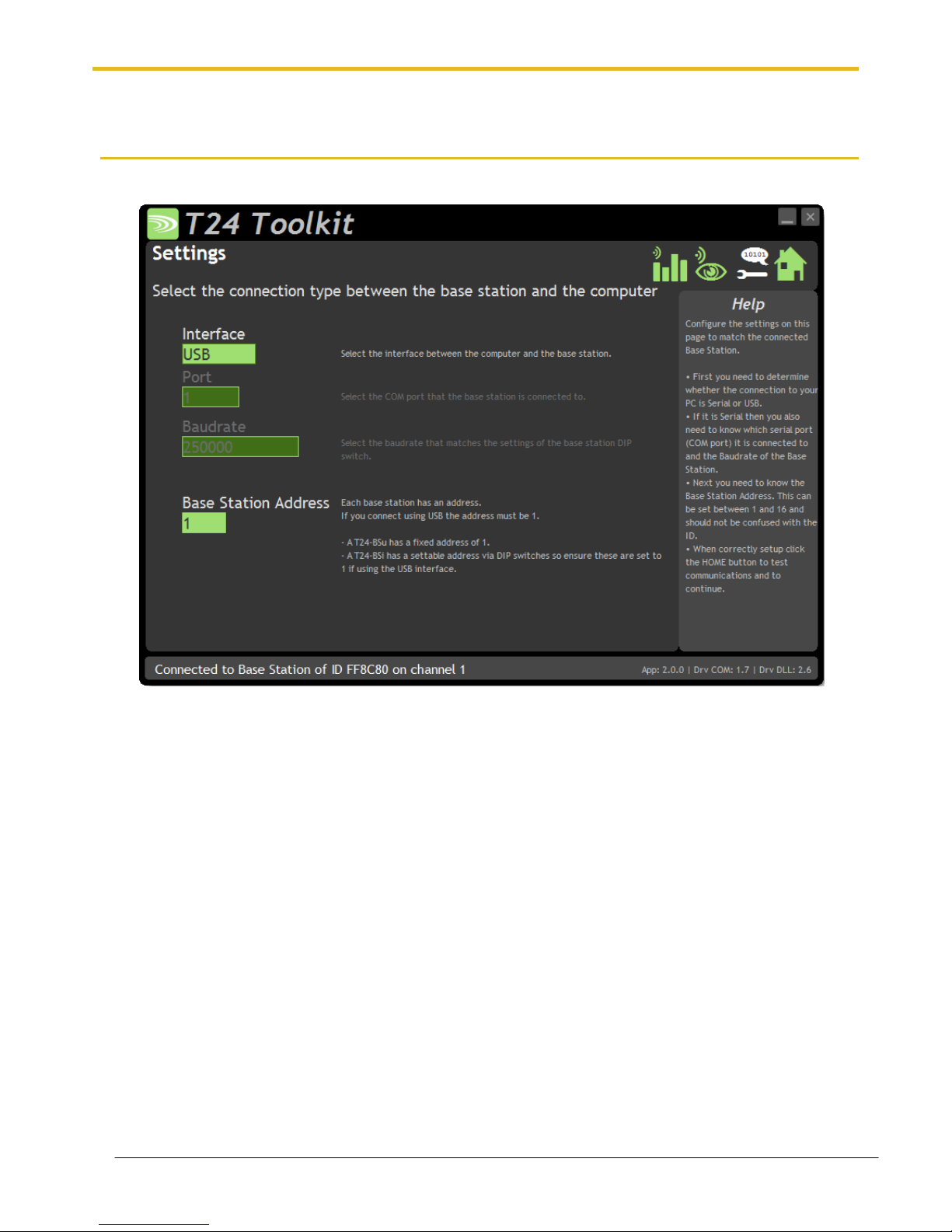
Setup Base Station Communications
Select the appropriate interface type for the connected base station. If the base station is connected via a serial
port then you will need to know the COM port it is connected to and the baud rate.
The Base Station Address is usually 1. This will only ever be different if it has been changed on base stations to
support multi base station configurations.
Click the Home button to attempt communications with the base station.
If no communications can be established the toolkit will remain on this page. You will need to check that the base
station is powered and that it is connected to any converters correctly.
Page 13
Mantracourt Electronics Limited T24 Telemetry User Manual
12
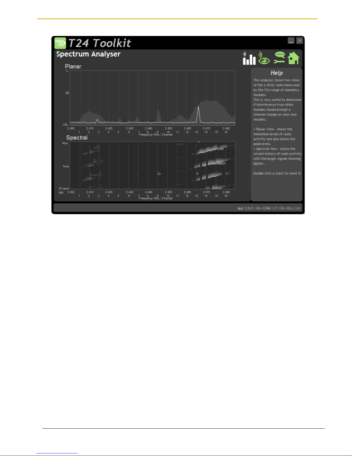
Analyser
The analyser page is provided as a tool and will not normally be needed unless you plan to change channels and
want to find the best channel to select, or to diagnose poor communications issues.
This page shows the radio signal levels detected across all the channels available to the X24 and T24 series of
modules. Using this tool may help in detecting noisy areas and allow you to decide on which channels you may
want to use.
The above charts show the traffic from a Wi-Fi network and it can be seen to be operating over channels 12 to 16
and it would be best (though not essential) to avoid using these channels.
Although 16 channels are shown the X24 and T24 modules operate over radio channels 1 to 15.
Page 14
Mantracourt Electronics Limited T24 Telemetry User Manual
13
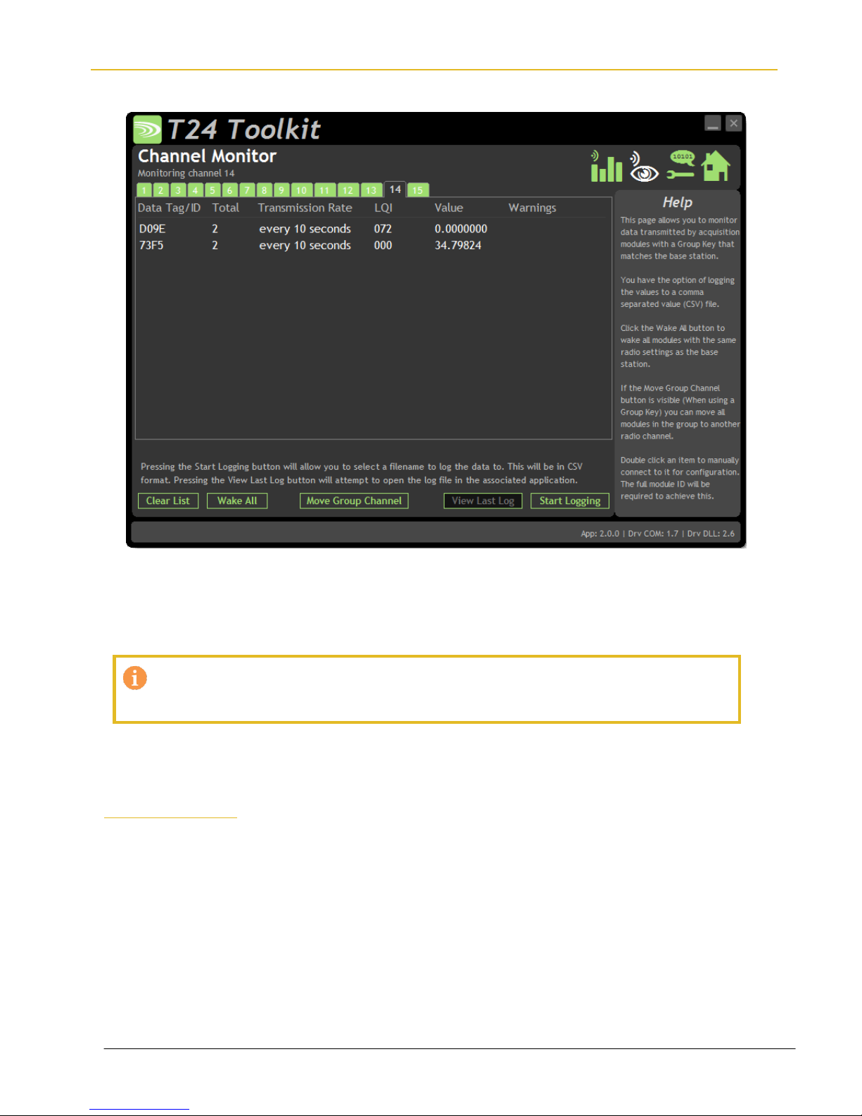
Channel Monitor
This page shows a summary of data sent by transmitter modules.
You can see the Data Tag of transmitted messages along with the total number of messages received, the
transmission rate, link quality, data value and any error messages.
Some base stations can also list modules that are sleeping. These will show an ID instead of a Data Tag.
To see any data the base station must be on the same radio channel as the transmitters and
must have a matching Group Key
The radio channel of the base station can be changed by clicking the channel tabs along the top of the page.
If you want to change the Group Key of the attached base station you need to configure its radio settings. See
Configure Base Station
Items you can change or interact with:
Radio Channel Tabs
Click a tab to change the radio channel the base station is operating on
Clear List
Clear all detected messages from the list
Wake All
Wake all modules on the current radio channel
Page 15

Mantracourt Electronics Limited T24 Telemetry User Manual
14
Start Logging
Asks for a filename then logs the received data to a CSV file in the following
format:
Data Tag, Elasped ms, Value
View Last Log
Will launch the application associated with CSV files and open the last logged
file.
Move Group Channel
If the base station has a group key set then this button will be visible. Once at
least one module is present in the list this button will become enabled. Clicking
it will ask the user for a new radio channel then all detected transmitters, along
with all other modules on the same channel and group key such as handhelds,
will all be moved to the selected channel. Once this has been achieved the base
station itself will move and the list will start to fill again with messages on the
new radio channel.
You will only see a list of detected transmitters on this page so
you will need to ensure that any other receiver modules in the
group are available to be woken.
When this button is clicked all modules on the same radio
channel and group key will be woken before they are changed
to the target radio channel.
Page 16
Mantracourt Electronics Limited T24 Telemetry User Manual
15
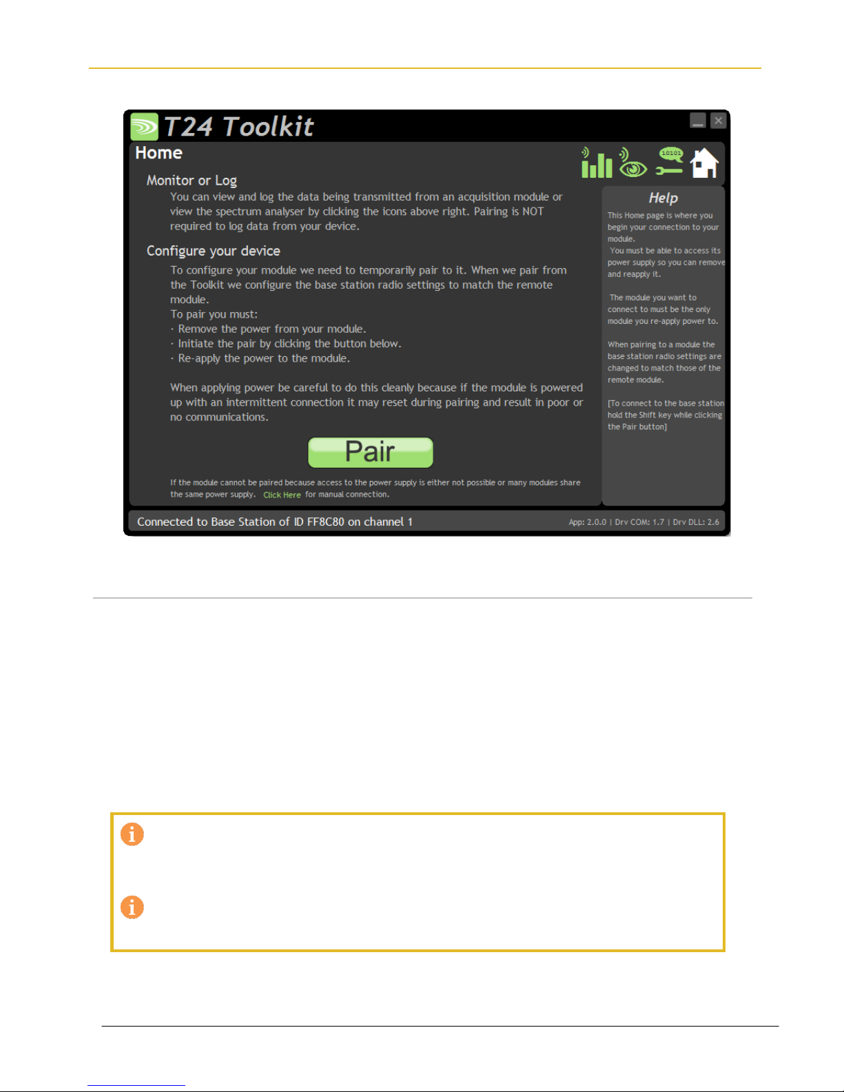
Home
You now have successful communications with the base station so you can now pair with your remote X24
module or you can select the Spectrum Analyser mode or Data Provider Monitor mode.
Connecting to a remote module
To connect to a remote module you will pair. This is achieved by power cycling the module. Pairing removes the
need to know the radio settings of the module you are connecting to and also ensures that it is in a suitable state
for configuration.
Pairing Procedure
Remove power from the X24 module.
Click the Pair button on the Toolkit.
You now have 10 seconds to re-apply power to the X24 module.
If you connect successfully the Toolkit will change to the Information page. If the pairing fails try again.
Pairing with the toolkit will not change the radio configuration settings of the connected
module. The base station radio settings will be changed to match those of the remote
module.
When the toolkit connects to a remote module to enable configuration it will usually inhibit
the normal operational transmission of messages
Page 17

Mantracourt Electronics Limited T24 Telemetry User Manual
16
Connecting to the attached base station module
To connect to and configure the connected base station, hold the shift key and click the Pair button.
Manual Connection
If you cannot get to the power supply of the remote module you can attempt to connect manually using Soft
Pairing. Click the ‘Click Here’ link at the bottom of the page and follow the prompts.
Page 18
Mantracourt Electronics Limited T24 Telemetry User Manual
17
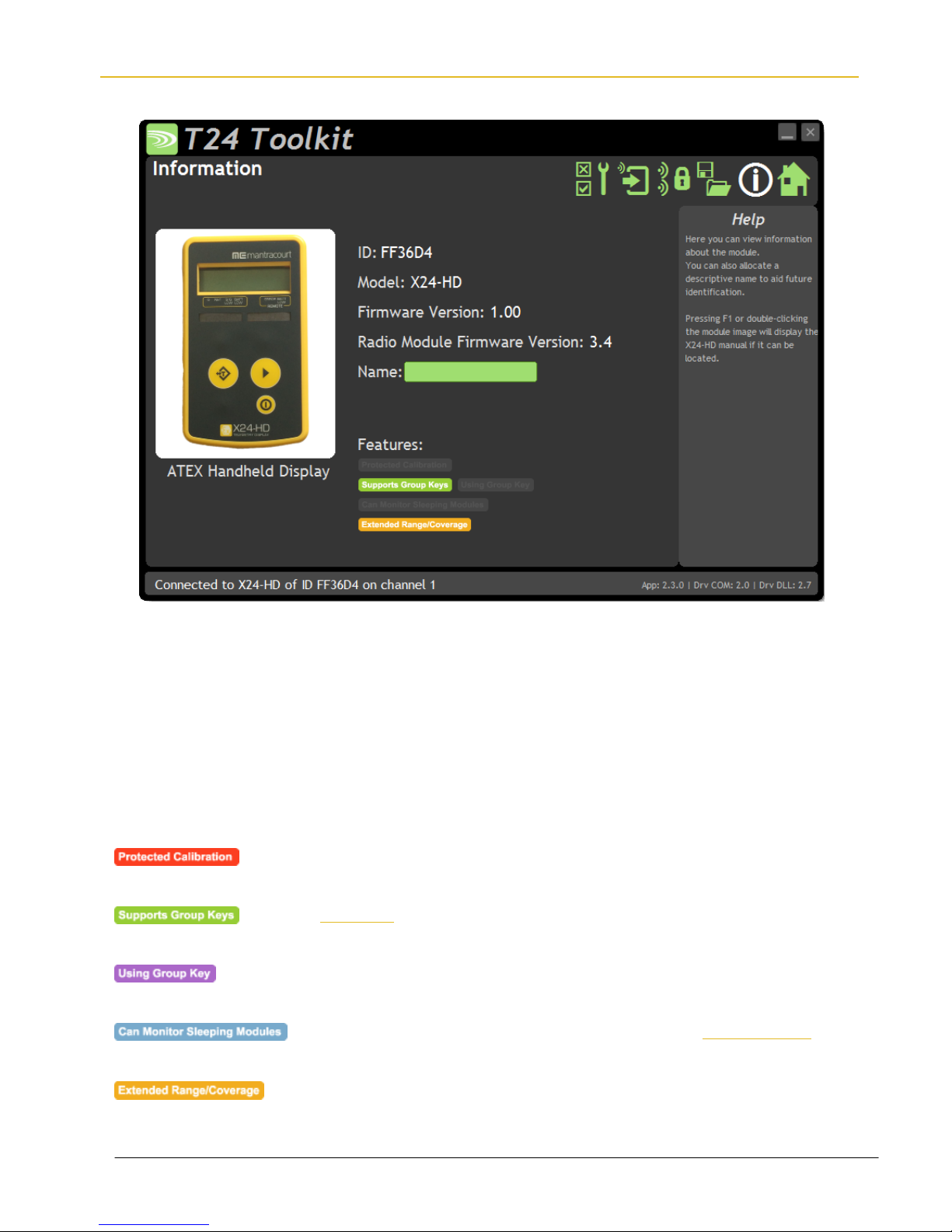
Information
Once successfully paired to a module this page is displayed showing you information about the connected
module.
Items you can change:
Name
You can enter a short description which may help you recognise this module in
the future.
Features
Each module may support certain features which are indicated on this page. If the feature is greyed out then it is
not supported. If it is coloured then it is supported.
Some transmitter modules may have had their calibration protected. This
indicates that you cannot calibrate this module.
Group Keys were introduced in 2015 so modules built before this date will not
support this feature. This indicates that the connected module can support them
This indicates that the connected module can support Group Keys and that one
has been configured for this module
Applicable to a base station only. This indicates that on the Channel Monitor page
modules that are sleeping will also be listed
Extended range radios were introduced to the T24 range in 2015. This indicates
that the connected module has an extended range radio fitted.
Page 19
Mantracourt Electronics Limited T24 Telemetry User Manual
18
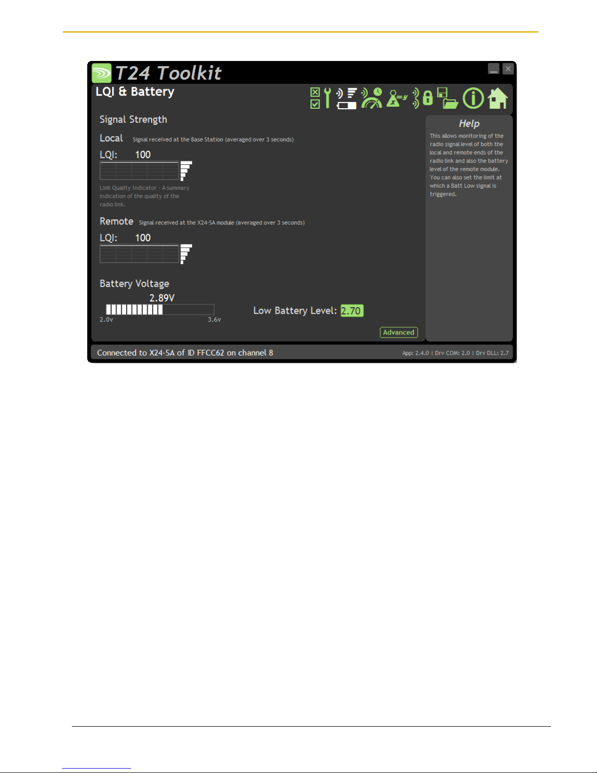
Battery and Radio Levels
Available for Transmitters only. Here you can see the voltage of the battery and the radio signal levels at the base
station and the remote transmitter module. This simple view gives an LQI value which stands for Link Quality
Indicator. This value will range from 0 to 100 and within this band you should still achieve communications. As the
level drops towards zero communications may become intermittent but still achievable.
On modules that are battery powered the battery voltage section will be visible. You can set the level at which the
transmitter module reports a low battery. (At 2.1 V the module will stop working)
If the battery voltage is below the Low Battery Level the bar will be coloured orange.
Items you can change:
Low Battery Level
Click this item to set the battery low level. For the Energizer L91 cells this should
be around 2.7 V.
Clicking the Advanced button will give more detailed information on the RSSI and CV levels of the received radio
packets.
Page 20
Mantracourt Electronics Limited T24 Telemetry User Manual
19
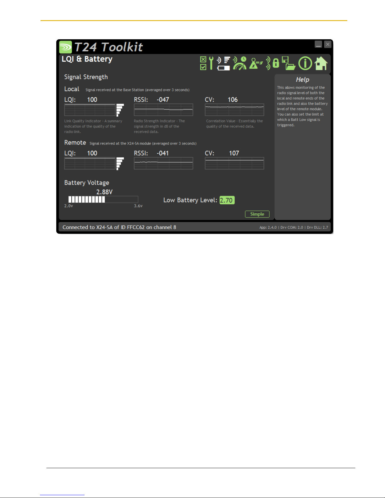
Battery and Radio Levels Advanced
LQI value which stands for Link Quality Indicator. This value will range from 0 to 100 and within this band you
should still achieve communications. As the level drops towards zero communications may become intermittent
but still achievable. This is calculated from the RSSI and CV values.
RSSI is effectively the received dB level which will range from about -30 which is a good signal to -98 which is a
weak signal.
CV is the correlation value and indicates how well the signal can be decoded. This ranges from 55 which is a poor
quality signal and 110 which is an excellent signal.
Page 21
Mantracourt Electronics Limited T24 Telemetry User Manual
20
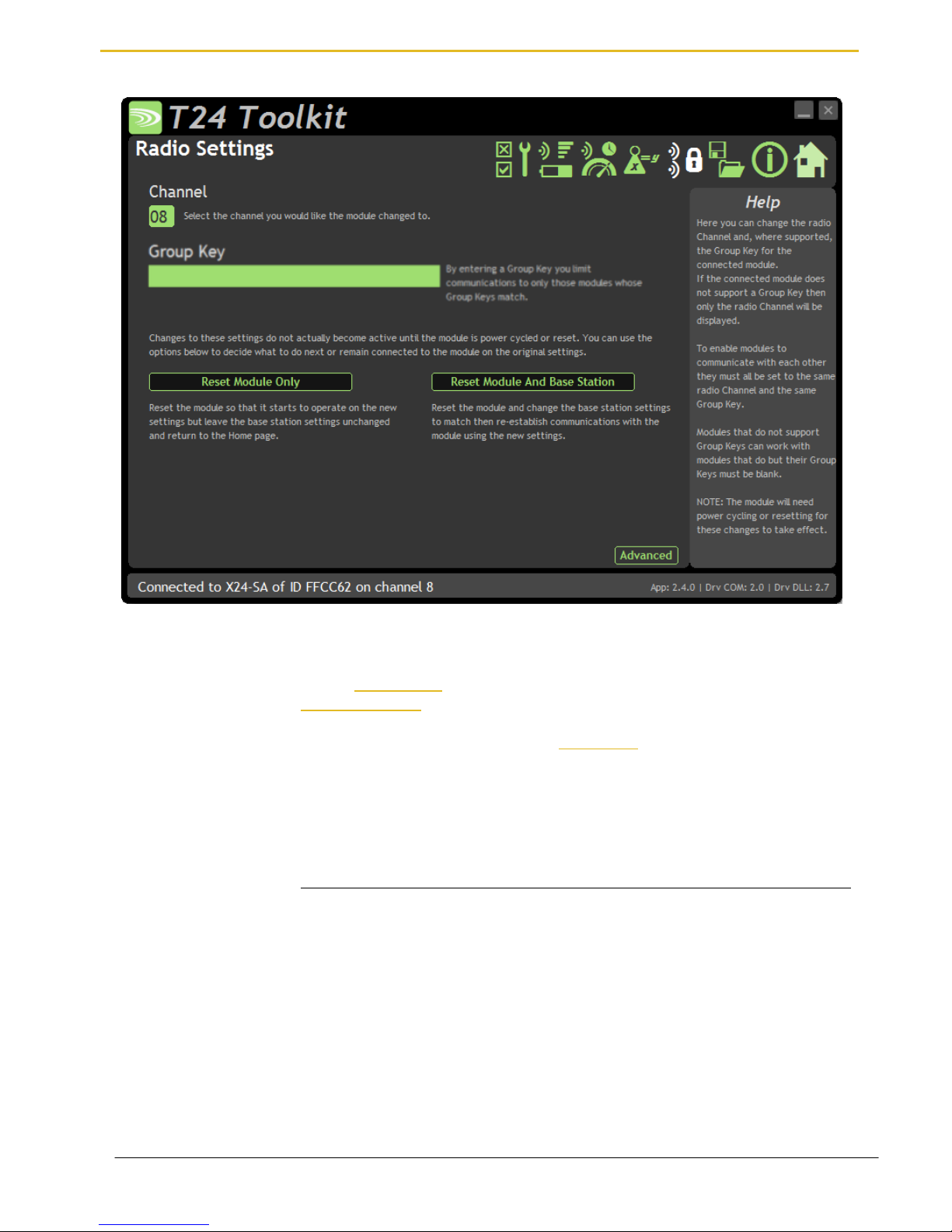
Radio Settings
Here you can change the channel and group key for the connected module.
Items you can change:
Channel
Select a radio channel between 1 and 15. The default is channel 1. You can use the
Spectrum Analyser mode to determine a good clean channel to use.
Group Key
Only visible on modules that support Group Keys.
Only modules with identical group keys can communicate. You can isolate groups of
modules on the same channel or just use the key to ensure the data cannot be read
by somebody else. Early versions of T24 modules do not support Group Keys and
this option will not be visible in the Toolkit.
To use modules that support Group Keys with older modules that do not then
the Group Key field must be blank.
The following two options are not visible when changing radio settings for a base
station. In that case changes are immediate.
Reset Module Only
Only enabled once a change has been made.
When radio settings are changed they do not take effect immediately but require a
reset or power cycle. This button forces the connected module to adopt the new
settings but keeps the base station on the existing settings. The home page is then
shown.
Reset Module and base
Station
Only enabled once a change has been made.
When radio settings are changed they do not take effect immediately but require a
reset or power cycle. This button forces both the connected module and the base
station to adopt the new changes and re-establishes a connection.
Page 22
Mantracourt Electronics Limited T24 Telemetry User Manual
21
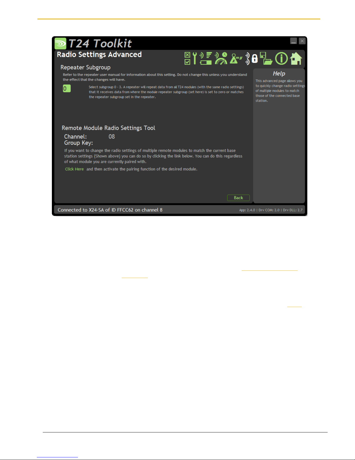
Radio Settings Advanced
Here you can change the repeater subgroup settings for the connected module. Also a tool is provided to quickly
match remote module radio settings to the base station radio settings.
Items you can change:
Repeater Subgroup
Select a repeater subgroup for this module. The default is zero which will let all
repeaters repeat messages from this module. See Repeaters and repeater
Subgroups
Remote Module Radio
Settings Tool
To quickly set a batch of remote modules to match the radio settings of the base
station you can use this tool. Usually this is arrived at by pairing with the base
station by holding the shift key whilst clicking the Pair button on the Home page.
To change the remote module radio settings:
Remove remote module power
Click the Click Here link on the page
Apply power to the remote module
The Toolkit will remain unchanged and still paired to whatever module or base
station it was paired to but the remote module will have changed its radio
settings.
Page 23

Mantracourt Electronics Limited T24 Telemetry User Manual
22
Save and Restore
Here you can save the module settings to a file on your PC so that they can be later loaded back into the same or
different module.
Items you can change:
Save
Click this button to open a file dialog window to allow you to select a filename
and location to save the configuration file to.
All configuration information including calibration data will be saved to the file.
The file extension is tcf.
Restore
Click this button to open a file dialog window to allow you to select a filename
and location of a previously saved file to load into the connected module.
All configuration information including user calibration data will be overwritten.
The file extension is tcf.
Page 24
Mantracourt Electronics Limited T24 Telemetry User Manual
23
Transmitter Modules
X24 Transmitters are the modules that connect to a sensor or have an input signal applied and periodically
transmit messages containing the value read from the sensor or input.
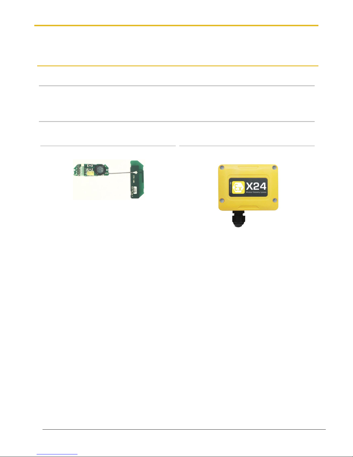
X24-ACMi-SA, X24-SAe, X24-SAi
Overview
The range of SA modules provide measurement from strain gauges and load cells. Formats available are
component OEM modules or enclosed versions.
Order Codes
X24-SAe
OEM strain transmitter module with external PCB
antenna on 60mm UFL cable.
T24-ACMi-SA
Strain transmitter module mounted in weatherproof
enclosure with battery holder for two Lithium Energiser
L91 AA batteries.
Page 25
Mantracourt Electronics Limited T24 Telemetry User Manual
24
Connections
X24-SAe, X24-SAi
Power
Attach power supply wiring to the module as shown below:
Connect to a 3 V power supply or batteries to the solder pads marked + and -.
For power requirements refer to the entity parameters:
Supply parameters
Groups I, IIC, IIIC
Ui
3.66V
Ii
340mA
Pi
1.244W
Ci
43μF
Li
5.64μH
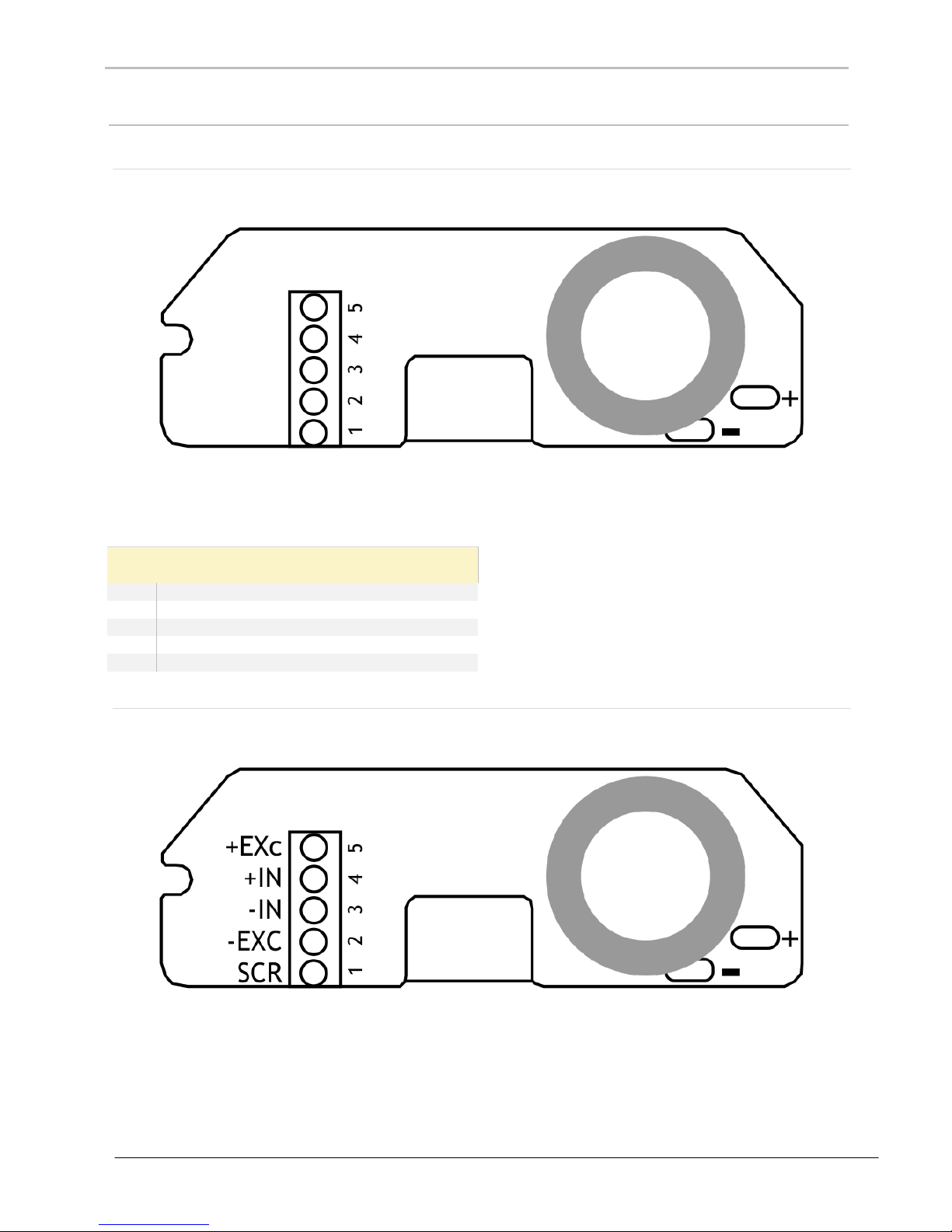
Sensor
Strain gauge connection is 4 wire as follows:
The resistance of the strain gauge can be between 85 and 5000 ohms. The X24-SA can support up to four 350
ohm strain gauges bridges attached in parallel (At the expense of reduced battery life).
The cable lengths between the X24-SA and the gauges should be kept below three meters and generally as short
as possible.
As the measurement is four wire then as the cable length increases the voltage drops in the cable will have more
of an effect on the factory mV/V calibration.
Page 26
Mantracourt Electronics Limited T24 Telemetry User Manual
25
The strain gauge measurement is bi-directional, i.e. tension & compression.
Refer to the following entity parameters:
Sensor connector parameters
Groups I, IIC, IIIC
Uo
5.5V
Io
2.25A
Po
1.25W
Co
15μF
Lo
1.38μH
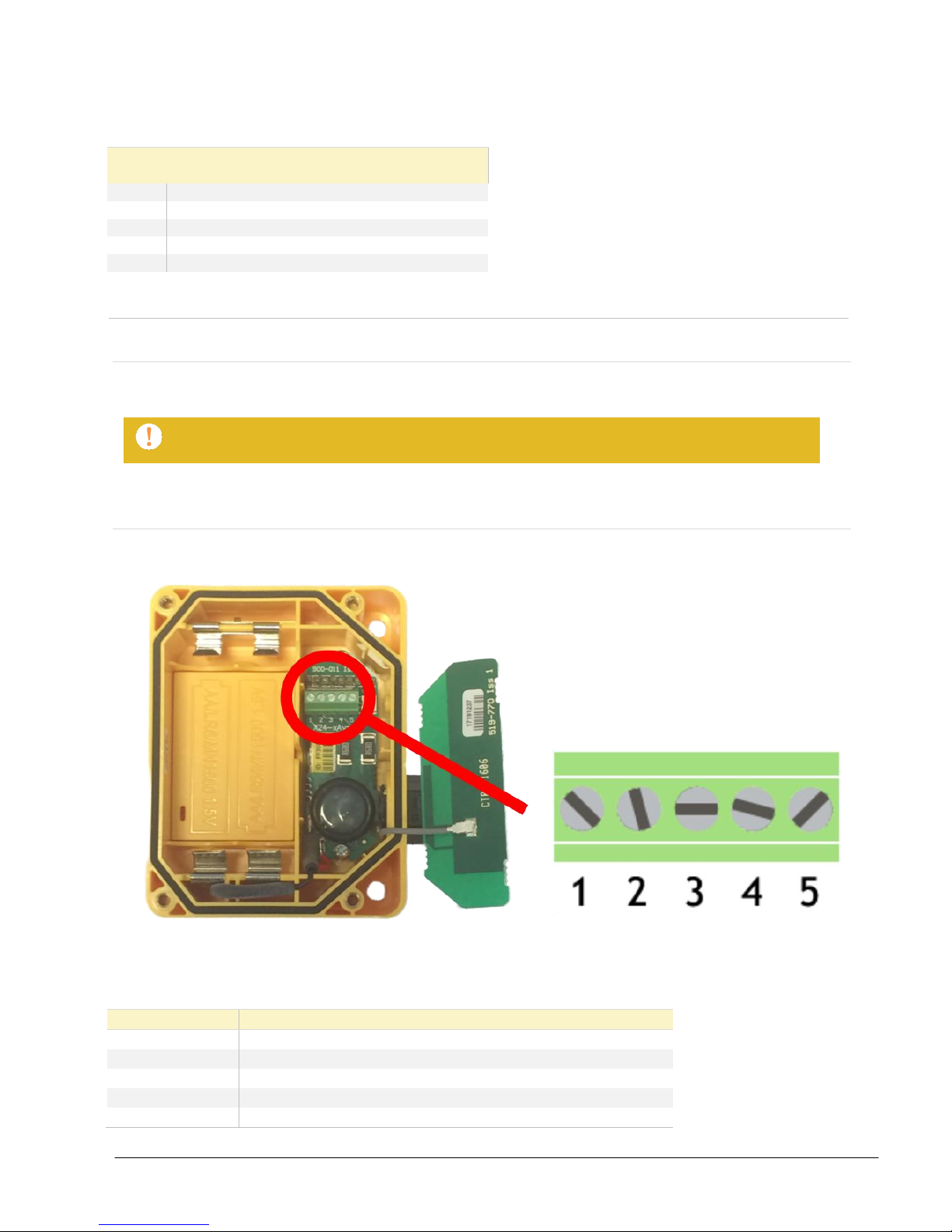
X24-ACMi-SA
Power
The enclosure is designed to accept two Energizer L91 AA lithium batteries.
Use only Energizer L91 cells. Do not change cells in an explosive atmosphere!
Sensor
The input connections are accessed by lifting the right hand cover plate, this plate incorporates the X24 Antenna;
take extra care when re-assembling that the grey UHF cable is attached to the antenna socket.
Screw Terminal
Function
1
Shield
2
- Excitation
3
-Signal
4
+Signal
5
+ 5 V Excitation
Page 27

Mantracourt Electronics Limited T24 Telemetry User Manual
26
Configuration
The T24 Toolkit provides a means of simple configuration and calibration of the transmitter module along with
useful tools to aid integration.
Launch the T24 Toolkit software application and pair to this module to enable the connection to the Toolkit to
allow configuration to take place. See Common Toolkit Pages - Home
Data Rates and Quality
This page allows you to select the rate at which data is transmitted from the transmitter module and the quality.
By selecting low power mode and entering some other information the toolkit will also give guides on achievable
battery life.
Note that the battery life calculator is assuming the best case scenario which is at 20 °C.
Items you can change:
Transmit Interval
Enter the transmission rate in milliseconds. The default is 333 giving
approximately 3 per second which is ideally suited to reading on a handheld.
You may want to slow this down to achieve longer battery life.
Sample Time
This is the length of time in milliseconds that the input is sampled before the
value is transmitted. This can vary between 5 milliseconds and close to the
Transmit Interval. A shorter sample time means that the module is awake for
less time so battery life is increased but at the expense of a reading with less
noise free resolution. You can vary this to see the effect on battery life and noise
free resolution.
Low Power Mode
Unless the transmitter module is non battery powered this should be set to Yes.
In between transmissions the transmitter module will enter sleep mode which,
Page 28

Mantracourt Electronics Limited T24 Telemetry User Manual
27
for some modules such as the strain gauge transmitter module, will have a
massive effect on battery life.
A reason for not using Low Power Mode would be if using the module in a
Master-Slave arrangement with PC for example.
Battery Type
This is not a parameter of the module but information used by the battery life
guide. You can choose from either the certified AA batteries or choose custom
to allow you to select your own battery capacity. See below. This will also offer
to change the Battery Low Level if the level suitable for the chosen battery is not
the level currently set.
Usable Capacity
This is not a parameter of the module but information used by the battery life
guide. This is the capacity of the battery in amp hours and has a profound effect
on battery life calculations. This capacity needs to be calculated from battery
manufacturer’s data sheets to take into account that you can only use batteries
down to 2.1 volts so in the case of twin AA cells this would be 1.05 volts.
Generally the usable capacity will not be as high as that advertised by the
battery manufacturer. Temperature and internal resistance of the battery are not
taken into account in the guide.
Sensor Impedance
This is not a parameter of the module but information used by the battery life
guide. Enter the resistance of the connected strain gauge in ohms.
Usage Per 24 Hour Period
Enter the number of hours per 24 hour period that the Transmitter will be
awake and transmitting.
Page 29

Mantracourt Electronics Limited T24 Telemetry User Manual
28
Calibration
Here you can calibrate the transmitter module and set a system zero if required.
This simple page allows semi-automated calibration where you can apply known inputs to calibrate.
This calibration includes linearization and is automatically applied.
See later for By Cert and Advanced page where you can adjust individual gains and offsets.
Calibration Process
Decide on how many points you will calibrate over.
Decide what weights will be applied (in ascending order) at each point.
Enter the actual input (in the required units) that you want the module to read at each point.
Now proceed to apply each input in turn (allowing a settle time) and click the Acquire button at that point.
You can now apply the next input and click Acquire until all the points are completed.
The mV/V from the load cell must be ascending through each calibration point.
The bottom of the page shows the Input Value and the Calibrated Value. Once the second point has been
acquired this Calibrated Value should display the actual calibrated value.
Items you can change:
Number of Calibration Points
Enter the number of points you wish to calibrate over. In its simplest form you
could select two for a linear calibration.
For more complex calibrations which include linearization select three to nine
points.
Point 1 - 9
For each point enter the engineering unit value that you want the transmitter
module to report at the applied input. i.e. 1.67
Page 30

Mantracourt Electronics Limited T24 Telemetry User Manual
29
Acquire 1 - 9
Click this button when the input has been applied and the reading has been
allowed to settle. This will acquire the reading and allow you to move to the
next points. You will be able to click the button again to re-acquire.
Start Again
Click here to restart the calibration.
System Zero
Once calibrated you may want to remove a fixed system value. In the case of a
strain gauge input this may be the weight of a sling, shackle, load bed etc.
Apply the required input and click here to set the system zero. The current input
will be removed from subsequent readings so that the reading will be zero.
To edit this value manually click the Advanced button.
System Zero is stored in non-volatile memory in the transmitter module.
By Cert.
You can click the By Cert button to calibrate against a sensor calibration sheet.
You just need to enter the input values and associated engineering unit
required output value of at least 2 points.
This will take you to a different screen.
Advanced
Clicking the advanced button will allow you to edit the gains and offsets for
each available calibration point. This will take you to a different screen.
The calibration for this transmitter may be locked in which case you will not have access to
these pages!
Page 31

Mantracourt Electronics Limited T24 Telemetry User Manual
30
Calibration by Certificate
In some circumstances it may not be possible to apply inputs in which case the calibration can be entered
manually from the calibration table or certificate for a load cell without ever having to connect the load cell.
Items you can change:
Number of Calibration Points
Enter the number of points you wish to calibrate over. In its simplest form you
could select two for a linear calibration.
For more complex calibrations which include linearization select three to nine
points.
Input Points 1 – 9
(mV/V shown in this
screenshot)
Enter the input point for which you will specify a required engineering output
value
Engineering Units 1 - 9
Enter the required engineering unit output for the specified input value
Calibrate
Click this button to calculate and update the module calibration
Page 32

Mantracourt Electronics Limited T24 Telemetry User Manual
31
Calibration Advanced
In some circumstances it may not be possible to apply inputs in which case the calibration can be entered
manually.
For example, if a strain gauge manufacturer provides a calibration table for a cell it may be possible to calculate
gains and offsets and enter these values into the Advanced Calibration page without having to connect the strain
gauge or apply weights.
Items you can change:
Number of Calibration Points
Enter the number of points you wish to calibrate over. In its simplest form you
could select two for a linear calibration.
For more complex calibrations which include linearization select three to nine
points.
Input Points 1 – 9
(mV/V shown in this
screenshot)
Enter the input point to which the associated interpolated gain and offset values
will be applied. Note between points the gain and offset values are linearly
interpolated. Inputs are extrapolated below point 1 and above point 9.
Gain 1 - 9
Enter the gain value for associated point
Offset 1 - 9
Enter the Offset value for associated point
System Zero
You can set the system zero value here or set it to zero to remove the system
zero effect.
Description of Linearisation Calculations
The input value is looked up in a table of points starting from point 1. If the input mV/V is greater than the mV/V
specified at that point then it is checked against the next point. When the best point has been found the Gain and
Offset values from that point are applied to the mV/V value as follows.
Value = (input * Gain) – Offset.
Page 33

Mantracourt Electronics Limited T24 Telemetry User Manual
32
Advanced Settings
You should not normally need to change these settings.
Items you can change:
Sleep Delay
Here you can enter a delay in seconds after which the transmitter module will
return to deep sleep if no Keep Awake message is heard from the X24-HD
handheld. The default is 60 seconds. Enter zero to disable automatic sleeping.
Data Tag
The data transmitted by the module is identified by a Data Tag. This is by
default set to the last 4 digits of the module serial number.
If by some chance you had two transmitter module modules that would be
working on the same channel and had the same last 4 characters in their ID (1 in
65,535 chances) you may want to change the data Tag of one of the modules
and perform pairing again with the X24-HD handheld.
Startup Time
Some transmitter modules power a sensor from their excitation voltage. When
coupled to a sensor with a slow startup time this setting is used to delay the
measurement after wakeup from sleep between readings. This gives the sensor
time to settle at the expense of battery life.
For strain gauge inputs this settings should be set to zero.
LED Mirror to Digital Output
When set to Yes the large LED will flash indicating a transmission, configuration
mode or when a handheld is looking at this Transmitter. This is very useful when
using an X24-HD handheld as the transmitter module LED will activate while the
handheld is in communications with the module.
Transmit power
Set the transmit power level from 0 – 100%. Default is 100%
Page 34

Mantracourt Electronics Limited T24 Telemetry User Manual
33
Enclosure & Mounting
This module is available in different enclosure types. Locate your module and follow the link to view dimensional
and mounting information for that particular enclosure.
X24-SAe, X24-SAi
These OEM modules are bare PCB modules. Please see Appendix A – Enclosures & Mounting – OEM Transmitter
Modules for more information.
X24-ACMi-SA
This module is fitted inside our medium enclosure. Please see Appendix A – Enclosures & Mounting – ACMi for
more information.
Antennas
X24-SAe
The X24-SAe module has an external antenna attached.
T24-ANTA PCB Antenna See Appendix B – Antennas – T24-ANTA
X24-ACMi-SA
These modules have the antenna already fitted inside the enclosure so there are no specific mounting
requirements.
Page 35

Mantracourt Electronics Limited T24 Telemetry User Manual
34
Specification
Specification with 1000R bridge, 2.5mV/V, at 3V supply at 25°C
Measurement
Min
Typical
Max
Units
Strain Gauge Excitation System
4 Wire
Strain Gauge Excitation Voltage
4. 5
5
5.25
Vdc
Strain Gauge Drive Capability
85
-
5000
Ω
Maximum Gauge Sensitivity (FR)
3.2
+/-mV/V
Offset Temperature Stability
1 4
ppm/°C
Gain Temperature Stability
3 5
ppm/°C
Offset Stability with Time
20
80
ppm of FR (1)
Gain Stability with Time
30
ppm of FR (2)
Non Linearity before Linearization
5 25
ppm of FR
Internal Resolution
16,000,000/ 24
Resolution/Bits
Noise Free where Sample Time < 10ms
50,000 / 15.5
Resolution/Bits
Noise Free where Sample Time < 50ms
65,000 / 16
Resolution/Bits
Noise Free where Sample Time < 100ms
150,000 / 17.25
Resolution/Bits
Noise Free where Sample Time < 1000ms
250,000 / 18
Resolution/Bits
Noise Free where Sample Time > 1000ms
400,000 / 18.75
Resolution/Bits
1. From original offset at any time.
2. First year.
Environmental
Min
Typical
Max
Units
Operating temperature range
-20
+50
°C
Storage Temperature
-40
+85
°C
Humidity 0
95
%RH
Power Supply
Min
Typical
Max
Units
Standby / Low Power Mode
5 20
µA
X24-SAe, X24-SAi, X24-ACMi-SA
Power Supply voltage
2.1
3.0
3.6
Vdc
Power Supply ripple
50
mV ac pk-pk
Normal Mode (1K Bridge)
60
65
mA (1)
1. Power supply must be capable of supplying 300 mA for 250 µs (Required on start up, waking and during low power operation)
Battery Life in Low Power Mode Generating
Results at 3Hz with 350R Load Cell
Usage
Battery Life
Pair Energizer L91 Lithium AA cells
Constantly on
30 days
Pair Energizer L91 Lithium AA cells
12 sessions per day of 5
minutes
2 years
Radio Range
To determine radio range please refer to Appendix B – Antenna Range
Page 36

Mantracourt Electronics Limited T24 Telemetry User Manual
35
Receiver Modules
Receiver modules use the messages sent by the transmitter modules. These modules may process or display this
information or convert the data into a different physical format. There are many more non ATEX/IECEx Receivers
in the T24 Telemetry range that will work with X24 Transmitters.
X24-HD
Overview
The X24-HD is a highly configurable handheld display capable of working with X24 or T24 Transmitter modules.
This allows wireless remote viewing of various remote inputs such as strain gauge or voltage etc. using 2.4 GHz
radio.
The remote transmitter module measures its input value (strain gauge, voltage, current etc.) and periodically
transmits it.
The X24-HD captures this data and displays it. The handheld can operate by displaying data from any transmitter
detected or you can define up to 24 specific transmitters to allow the operator to cycle through.
Grouping functions allows up to 8 group totals to be viewable. Each group or individual transmitter has user
defined name, scaling, display format, zero functions and overload settings.
Order Codes
X24-HD
Handheld display module in a robust weatherproof enclosure.
Connections
Power
The handheld module is powered by two lithium Energizer L91 AA batteries.
Use only Energizer L91 cells. Do not change cells in an explosive atmosphere!
Page 37

Mantracourt Electronics Limited T24 Telemetry User Manual
36
Quick Start
This section will show you how to get the handheld and a Transmitter working out of the box.
You will require two Energizer L91 AA lithium batteries for the handheld and a 3 V dc supply for the transmitter
module which may also be a pair of AA batteries.
Connecting Power
X24-HD
Remove the two screws on the rear battery compartment. Insert two AA batteries. Refit the battery compartment
cover. The handheld module is now switched on and will display BUSY until it detects a Transmitter.
Transmitter Module
See the relevant transmitter module manual section for information about connecting power.
Viewing Transmitter Data
The factory default setting for the handheld is that no specific Transmitter modules are configured so it will
display data from any Transmitter on the same radio channel and using the same Group Key.
If you have purchased the handheld and Transmitter module at the same time then both will default to radio
channel 1 and a blank Group Key.
Once power has been applied to the Transmitter the handheld will briefly display its Data Tag then show its value
on the LCD. If you have more than one Transmitter then pressing the Next key (Triangular arrow) will move to the
next available Transmitter.
Note that when no Transmitters are specified as inputs the handheld will wake up sleeping
Transmitter modules as it detects them but it will not send them to sleep. After the handheld
is turned off the Transmitters will remain awake. Use Sleep Delay setting in Transmitters to
ensure they turn off again when the handheld is turned off or moves out of range.
Page 38

Mantracourt Electronics Limited T24 Telemetry User Manual
37
Operation
Keys
The keys have two functions. A short press is a press and release. A long press is press and hold for around 2
seconds.
Power Key
Long Press – Powers the handheld on and off. Hold the power key until the
display shows BUSY then release the key.
Quick Press - Toggle the backlight on and off when in manual backlight mode.
Next Key
Short Press - Step to the next Transmitter or group. A brief prompt will be
displayed before the value is shown which will either be the Transmitter Data Tag
or a user defined name.
Long Press - Display the Data Tag or name of the currently viewed Transmitter or
group without moving to the next.
T
Tare Key
Short Press - This will toggle between gross and zeroed net mode. i.e. If the
display shows gross then pressing the key will zero the display. Pressing the key
when in net mode will return the display to gross mode. The Gross and Net
modes are indicated as described below. Gross and Net states are retained
through power off.
Long Press - When in net mode will briefly display the Gross value but remain in
net mode.
Indicators
G
The display is showing Gross weight.
NET
The display is showing Net weight.
SIG LOW
The radio signal from the transmitter module is low. The module is still
functioning but the limit of the range may be near. Communications may start to
deteriorate when this indicator is visible. Until ------ is displayed the
communications are still OK and the display can be relied on for accuracy.
Even with a degraded signal the display value will always be
correct.
BATT LOW
The batteries in the handheld are low and need to be replaced.
REMOTE ERROR
The transmitter module has an error that the handheld does not recognise.
REMOTE BATT LOW
The battery or supply to the transmitter module is low.
Page 39

Mantracourt Electronics Limited T24 Telemetry User Manual
38
Errors
Displayed on handheld LCD.
Error 1
The transmitter module has a strain gauge input and is in shunt calibration mode.
An external module has placed the transmitter module in Shunt Calibration mode
so rather than display a misleading reading this error is displayed instead.
Modules such as the X24-SA support this error type.
Error 2
Input integrity error. The transmitter module has found a problem with the input.
There may be open or short circuits. Rather than display a misleading reading this
error is displayed instead.
Only certain transmitter modules support this error such as the X24-SA.
Overload
The overload limit set by the user has been exceeded.
Page 40

Mantracourt Electronics Limited T24 Telemetry User Manual
39
Configuration
The T24 Toolkit provides a means of simple configuration of the handheld module along with useful tools to aid
integration.
Launch the T24 Toolkit software application and pair to this module to enable the connection to the Toolkit to
allow configuration to take place.
Remove a handheld battery (Not in hazardous area!), click Pair in the Toolkit and replace battery to perform a full
pairing. This will work regardless of the radio settings in either the base station or the handheld.
If you know that the radio channel and group key settings of the base station and the handheld are the same you
could soft pair to the handheld by performing a manual pair in the Toolkit and just entering the ID of the
handheld.
See Common Toolkit Pages - Home
Modes of Operation
The handheld will allow you to view data from multiple transmitters and also allow the viewing of the sum of
multiple transmitters. How the handheld operates depends on how you configure its list of transmitters (‘Inputs’)
and optional summing groups.
When the handheld is turned on it will wake all transmitters using the same radio channel and group key if you
have selected this feature.
No List Entered (Default)
In its simplest, out of the box, configuration the handheld has no transmitter inputs specified. In this mode the
handheld will display data from any transmitter using the same radio channel and group key. To make things
easier you can set a list Set Size so that the Next key just cycles around the n highest signal transmitters. This has
a useful effect when setting the list size to 1 in that you can walk up to a transmitter, press the Next key and
effectively select that one for viewing (as that will be the highest signal transmitter detected). As the different
transmitters are cycled through, their Data Tags will be displayed briefly before their transmitted value is shown.
In this mode the transmitters should have their Sleep Delay settings enabled so that they go back to sleep after
the handheld is turned off or out of range as the handheld will wake all transmitters but not send them back to
sleep. (Equivalent to the roaming capability of the T24-HR handheld)
List Entered
When you know which transmitter or transmitters are in your system (or you want to limit viewing to a certain
collection of transmitters) you can enter up to 24 in the handheld’s list of transmitters. The advantage over not
having a list is that you can name each transmitter so their name is shown on the display instead of their Data Tag
as they are selected. You can also configure each input separately for overload, format and scaling etc.
In this mode, if the option to sleep and wake transmitters is enabled, the transmitters will be sent to sleep when
the handheld is turned off.
List Entered Plus Summing Groups
Once you have entered at least one transmitter input in the list you also have the option of creating summing
groups. Up to eight groups can be defined and any of the inputs can be defined as belonging to any of the
groups. In this mode the Next key cycles around the groups instead of the individual inputs. Each summing group
will display the summed total of all its constituent inputs. Groups have user defined names as well as overload
levels, scaling and formats. Unless disabled you can also ‘drill down’ and look at the groups constituent inputs.
Page 41

Mantracourt Electronics Limited T24 Telemetry User Manual
40
Global Settings
Here you can adjust the settings common to all modes of operation.
Items you can change:
Global Timeout (s)
This is how long the handheld will wait with no data received from the viewed
transmitter before indicating that the signal has been lost. This should be set to at least
twice the slowest transmitter interval.
Do Sleep Wake
Select this feature to enable the handheld to wake and sleep transmitters. When no
transmitters are defined all sleeping transmitters (on the same radio channel and using
the same Group Key) will be woken as they come into range of the handheld.
Transmitters will not be sent to sleep regardless of this setting.
When transmitters have been defined the handheld operated a little differently. For the
first 12 seconds after turning the handheld on all transmitters will be woken (not only
those defined). But on turning off the handheld the transmitters in the list will be sent to
sleep.
Backlight Control
Select whether to disable or enable the backlight. If enabled you can chose to turn it on
as soon as the handheld turns on and have control over its state using the power key
(short press) or you can choose to operate automatically whereby the light comes on
when a key is pressed and goes off after 30 seconds.
Auto Power Off
Set a time in minutes after which the handheld will turn off if no keys have been
pressed. Set to zero to disable this feature. Will require a power cycle to change.
Buzzer Control
Here you can select whether the buzzer will sound when certain states are active.
Leading Zero
Suppression
This will remove leading zeros from displayed values in all modes.
Page 42

Mantracourt Electronics Limited T24 Telemetry User Manual
41
Activate Viewed Input
LED
When no transmitters are defined the transmitter currently being viewed will always
activate its LED regardless of this setting. When any transmitters are defined then the
transmitters LEDs will only activate when being viewed if this setting is activated.
Although this setting is OK to use with all X24 transmitters this
feature should be disabled when being used with T24 transmitters
with firmware versions below 04.00 as their LEDs may remain on
when turning off the handheld.
Page 43

Mantracourt Electronics Limited T24 Telemetry User Manual
42
Configure Inputs
No Defined Transmitters
This page will be displayed when no transmitter list has been defined.
Here you can adjust the settings common to all displayed transmitter values.
Items you can change:
Set Size
This setting determines how many transmitter modules, with the highest signal levels,
make up the set through which the Next key cycles.
Based on the application and how many transmitter modules are in the vicinity of the
handheld this list size can affect how the operator uses the handheld. See Example
Configuration Scenarios
Format & Resolution
Here you can define how the values are displayed on the LCD. There are 7 digits
available and you can define where the decimal point is shown by entering numerals
where a zero indicates a numeric digit position.
When the data is being displayed the number of decimal places you define may be
overridden as the display will always show the correct number of integer digits.
Example: If you set the format to 000.0000 and the value to display is 1000.1234 the
display will show 1000.123
You can also define the resolution, which is the block size of changes to the display.
Example: If you enter the format as 000.0005 the display will only change in steps of
0.0005 which can be used to mask noisy digits at high resolutions.
Page 44

Mantracourt Electronics Limited T24 Telemetry User Manual
43
Zero Indication Band
Using this setting you can mask tiny changes in input after you press the Tare button.
Entering zero will disable this function.
Entering a non-zero value will provide a band within which the display will always read
zero.
Once the reading exceeds this value the real weight will be displayed as no taring is
taking place.
Example: You are adding boxes to a platform and you press tare between adding each
one so you can see the weight of each box.
Without this setting activated each time you tare the display will be around zero but not
exactly zero (By setting the display resolution you may also hide this difference) by
setting a small value here such as 0.2kg the display will show a stable zero while actual
weight is fluctuating less than ± 0.2kg.
Overload
You can enter a limit here above which ‘Overload’ will be shown on the display instead
of the actual value. Applies to the gross input value including any custom scaling.
Enter zero to disable this feature.
Define Transmitters
Click the ‘Define’ button to display the page that allows you to define Transmitters.
Page 45

Mantracourt Electronics Limited T24 Telemetry User Manual
44
Defined Transmitters
These pages will be displayed when at least one Transmitter has been defined or you click the ‘Define’ button on
the page shown when no transmitters are defined (See previous page).
General Tab
Here you can adjust the general settings for the selected Transmitter input. Select the required input by clicking
the numbered tabs along the top of the page.
Items you can change:
Data Tag
By entering a Data Tag you enable this Transmitter Input. Enter zero to disable this
input. You can enter Data Tags in any of the 24 available slots. The Next button will just
cycle between those entered.
Name
As you cycle between available transmitters with the Next key an identifier is shown
briefly before the value is displayed. If you enter text here then this will be shown but if
you leave this blank the Data Tag will be shown.
Some letters cannot be displayed on a 7 segment LCD digit. You cannot use letters M,
W or K. Some letters will look alike. i.e. Z and 2. The LCD Preview will show how the
entered name will look on the display.
Page 46

Mantracourt Electronics Limited T24 Telemetry User Manual
45
Format
Here you can define how the values are displayed on the LCD. There are 7 digits
available and you can define where the decimal point is shown by entering numerals
where a zero indicates a numeric digit position.
When the data is being displayed the number of decimal places you define may be
overridden as the display will always show the correct number of integer digits.
Example: If you set the format to 000.0000 and the value to display is 1000.1234 the
display will show 1000.123
You can also define the resolution, which is the block size of changes to the display.
Example: If you enter the format as 000.0005 the display will only change in steps of
0.0005 which can be used to mask noisy digits at high resolutions.
Overload Limit
You can enter a limit here above which ‘Overload’ will be shown on the display instead
of the actual value. Applies to the gross input value including any custom scaling.
Enter zero to disable this feature.
Switch Back to
Roaming Mode
Click the ‘Clear All’ button to remove all of the transmitters and group settings to return
to the roaming mode with no transmitters defined.
The changes you make are not saved to the handheld until you click on a new input tab or
select another page to view.
Page 47

Mantracourt Electronics Limited T24 Telemetry User Manual
46
Zero Tab
Here you can configure the zero settings for the selected Transmitter input.
Items you can change:
Power On Zero
Here you can determine whether the X24-HD performs automatic zero when it is
powered on.
Enter zero to disable this function.
If you enter a non-zero value then when the handheld is first turned on it checks the
value read from the transmitter module. If this falls within ± of this value then the
display will be altered so this reads zero.
Example: A strain gauge transmitter module (X24-SA) is calibrated in kg and measures
the weight of boxes on a platform. The weight of the platform itself has been removed
using system zero on the transmitter module.
Sometimes there is debris on the platform which you do not want to see when viewing
the weight of boxes that will be placed on the platform later.
The minimum weight of a box is 5 kg so you could set the Power On Auto Zero to 2 kg.
When you turn on the handheld, if the weight on the platform is between -2 and +2kg
then the handheld will tare this weight off and so read zero.
Page 48

Mantracourt Electronics Limited T24 Telemetry User Manual
47
Zero Indication Band
Using this setting you can mask tiny changes in input after you press the Tare button or
are close to zero in gross mode.
Entering zero will disable this function.
Entering a non-zero value will provide a band within which the display will always read
zero.
Once the reading exceeds this value the real weight will be displayed as no taring is
taking place.
Example: You are adding boxes to a platform and you press tare between adding each
one so you can see the weight of each box.
Without this setting activated each time you tare the display will be around zero but not
exactly zero (By setting the display resolution you may also hide this difference) by
setting a small value here such as 0.2kg the display will show a stable zero while actual
weight is fluctuating less than ± 0.2kg.
Switch Back to
Roaming Mode
Click the ‘Clear All’ button to remove all of the transmitters and group settings to return
to the roaming mode with no transmitters defined.
The changes you make are not saved to the handheld until you click on a new input tab or
select another page to view.
Page 49

Mantracourt Electronics Limited T24 Telemetry User Manual
48
Scaling Tab
Here you can configure the scaling for the selected Transmitter input.
Use the Gain and Offset to manipulate the input value. This can perform quite a few useful functions such as:
Zero an Input – If a particular Transmitter value has a value that you want to remove but do not want to perform
a system zero at the transmitter end you can use the Offset to remove that value. Setting the Offset to 10 will
remove 10 from the transmitted value.
Convert Units – If the transmitter was calibrated in kg and you wish to display the value in lbs you can set a Gain
of 2.20462 and an Offset of 0.0
Change Polarity – If the Transmitted value was negative but you wanted to display a positive value set the Gain
to -1.0 and the Offset to 0.0
Actual Displayed Value = Transmitted Value * Gain - Offset
Items you can change:
Gain
This value will be multiplied by the transmitted value to provide the actual displayed
value. The default is 1.0
Offset
This offset will be applied to the transmitted value (After gain is applied) to provide the
actual displayed value. The default is 0.0
Switch Back to
Roaming Mode
Click the ‘Clear All’ button to remove all of the transmitters and group settings to return
to the roaming mode with no transmitters defined.
Page 50

Mantracourt Electronics Limited T24 Telemetry User Manual
49
Group Membership Tab
Here you can assign the selected Transmitter input to belong to any of the Summing Groups.
Items you can change:
8 Available Summing
Groups
The 8 available Summing Groups are shown here regardless of whether a group has
been defined or not. Simply select Yes or No to indicate whether this Transmitter Input
will contribute to that group’s total value.
Configure Groups
Button
Clicking this button will open the Summing Groups page.
Switch Back to
Roaming Mode
Click the ‘Clear All’ button to remove all of the transmitters and group settings to return
to the roaming mode with no transmitters defined.
The changes you make are not saved to the handheld until you click on a new input tab or
select another page to view.
Page 51

Mantracourt Electronics Limited T24 Telemetry User Manual
50
Summing Groups
General Tab
Here you can configure general settings for the selected Summing Group. Select the group by clicking the
numbered tabs along the top of the page.
As soon as at least one Summing Group has been enabled (By naming it) then the
handheld will only cycle through the Summing Groups instead of the individual inputs. The
values shown will be the sum of all the individual inputs that are members of that group.
Items you can change:
Name
Summing Groups are enabled by giving them a name. Leave the name blank to disable
the selected group.
As you cycle between group totals with the Next key an identifier is shown briefly
before the total is displayed.
Some letters cannot be displayed on a 7 segment LCD digit. You cannot use letters M,
W or K. Some letters will look alike. i.e. Z and 2. The LCD Preview will show how the
entered name will look on the display.
Page 52

Mantracourt Electronics Limited T24 Telemetry User Manual
51
Format & Resolution
Here you can define how the values are displayed on the LCD. There are 7 digits
available and you can define where the decimal point is shown by entering numerals
where a zero indicates a numeric digit position.
When the data is being displayed the number of decimal places you define may be
overridden as the display will always show the correct number of integer digits.
Example: If you set the format to 000.0000 and the value to display is 1000.1234 the
display will show 1000.123
You can also define the resolution, which is the block size of changes to the display.
Example: If you enter the format as 000.0005 the display will only change in steps of
0.0005 which can be used to mask noisy digits at high resolutions.
Overload
You can enter a limit here above which ‘Overload’ will be shown on the display instead
of the actual value. Applies to the gross input value including any custom scaling.
Enter zero to disable this feature.
Allow Drilldown
When at least one Summing Group has been named the Next key will cycle through
group totals rather than individual inputs.
If you allow drilldown then holding the Next key for a long press will start to display the
individual inputs that are members of the group. Each press of the Next key will show
the next input in the group. After the last input has been shown the display will revert
back to displaying the groups again.
Back Button
Click the ‘Back’ button to display the Transmitter Inputs pages again.
The changes you make are not saved to the handheld until you click on a new input tab or
select another page to view.
Page 53

Mantracourt Electronics Limited T24 Telemetry User Manual
52
Zero Tab
Here you can adjust the zero of the selected summing group.
Items you can change:
Zero Indication Band
Using this setting you can mask tiny changes in input after you press the Tare button.
Entering zero will disable this function.
Entering a non-zero value will provide a band within which the display will always read
zero.
Once the reading exceeds this value the real weight will be displayed as no taring is
taking place.
Example: You are adding boxes to a platform and you press tare between adding each
one so you can see the weight of each box.
Without this setting activated each time you tare the display will be around zero but not
exactly zero (By setting the display resolution you may also hide this difference) by
setting a small value here such as 0.2kg the display will show a stable zero while actual
weight is fluctuating less than ± 0.2kg.
Allow Drilldown
When at least one Summing Group has been named the Next key will cycle through
group totals rather than individual inputs.
If you allow drilldown then holding the Next key for a long press will start to display the
individual inputs that are members of the group. Each press of the Next key will show
the next input in the group. After the last input has been shown the display will revert
back to displaying the groups again.
Back Button
Click the ‘Back’ button to display the Transmitter Inputs pages again.
Page 54

Mantracourt Electronics Limited T24 Telemetry User Manual
53
Page 55

Mantracourt Electronics Limited T24 Telemetry User Manual
54
Scaling Tab
Here you can configure the scaling for the selected Summing Group.
Use the Gain and Offset to manipulate the summing groups value. This can perform quite a few useful functions
such as:
Zero a Sum – If the sum of the Transmitters have has a value that you want to remove but do not want to
perform a system zero at each of the transmitters you can use the Offset to remove that value. Setting the Offset
to 10 will remove 10 from the sum for example.
Convert Units – If the transmitters were calibrated in kg and you wish to display the sum in lbs you can set a Gain
of 2.20462 and an Offset of 0.0
Change Polarity – If the sum value is negative but you want to display a positive value set the Gain to -1.0 and
the Offset to 0.0
Actual Displayed Value = Transmitted Values Sum * Gain - Offset
Items you can change:
Gain
This value will be multiplied by the transmitted sum value to provide the actual
displayed value. The default is 1.0
Offset
This offset will be applied to the transmitted sum value (After gain is applied) to provide
the actual displayed value. The default is 0.0
Page 56

Mantracourt Electronics Limited T24 Telemetry User Manual
55
Allow Drilldown
When at least one Summing Group has been named the Next key will cycle through
group totals rather than individual inputs.
If you allow drilldown then holding the Next key for a long press will start to display the
individual inputs that are members of the group. Each press of the Next key will show
the next input in the group. After the last input has been shown the display will revert
back to displaying the groups again.
Back Button
Click the ‘Back’ button to display the Transmitter Inputs pages again.
Page 57

Mantracourt Electronics Limited T24 Telemetry User Manual
56
Members Tab
Here you can see a list of inputs that are members of the selected Summing Group and whose transmitted values
are summed to create the value displayed by the group. The list will display the name of the input or the Data Tag
if no name is assigned.
Items you can change:
Allow Drilldown
When at least one Summing Group has been enabled, by entering a Name, the Next key
will cycle through the Summing Group totals rather than individual inputs.
If you allow drilldown then holding the Next key for a long press will start to display the
individual inputs that are members of the group. Each press of the Next key will show
the next input in the group. After the last input has been shown the display will revert
back to displaying the groups again.
Back Button
Click the ‘Back’ button to display the Transmitter Inputs pages again.
Page 58

Mantracourt Electronics Limited T24 Telemetry User Manual
57
Example Configuration Scenarios
Examples Using No Defined Transmitter List (Roaming Mode)
The following two examples show scenarios where it would be impractical to define each available transmitter
because either there are more than 24 transmitters or the transmitters available may change and re-configuration
of the handheld is undesirable.
So for these examples the handheld has no Transmitter Inputs defined and therefore operates in ‘Roaming’ mode
where it can display the value from any transmitter on the same radio channel and Group Key. In both cases the
Sleep Delays of the Transmitters are set to 30 seconds as in this mode the handheld will wake the Transmitters
but not send them to sleep.
Long Bridge
A 1000m bridge has transmitters placed along its length at 10m intervals. Periodically an operator must record
the values from each of these transmitters. By choosing a Set Size of 10 the operator can start at one end of the
bridge and click the next key to cycle around the ten nearest Transmitters. Once the operator starts to see
transmitters already seen he can walk further up the bridge to cycle around a new set of 10. As the operator
moves along the bridge and comes into range of Transmitters they are woken automatically by the handheld. As
the handheld moves out of range of a transmitter it will return to sleep because of its Sleep Delay.
Brewery
A chemical company has a large storage room filled with barrels sitting on weigh scales containing Transmitters.
Each Transmitter has its LED visible so when the handheld is displaying the value from a particular barrel the
operator has visual feedback of the selected barrel. Because the operator needs to put a sticker on those barrels
that are less than a certain weight he needs to approach each barrel individually. By using a Set Size of 1 on the
handheld, each press of the Next key will effectively select the Transmitter with the highest transmission signal
level so as the operator approaches each barrel and presses the Next key he would see the LED light on the
nearest barrel’s Transmitter LED and therefore know he was looking at the weight for the correct barrel without
having to pay attention to the displayed Data Tag.
Example of Defined Transmitter List
Single Transmitter
The Data Tag of a Transmitter connected to a guy line is defined as the only input. Now when the handheld is
turned on the Transmitter is woken and the operator can read the tension in the guy line. On turning off the
handheld the Transmitter is sent to sleep to conserve its battery.
Multiple Transmitters
Three cranes are monitored by a single handheld so the Transmitter on each crane is defined in the Transmitter
Input list. Inputs are named as Crane 1, Crane 2 and Crane 3 so as the operator clicks the Next key he can see
which crane he is monitoring. A long press on the Next key verifies the currently viewed crane name without
moving on to the next one.
Example of Summing Groups
Alternative Units
A material vessel sits on two loadcells and the operator wants to view the total load in both tonnes and lbs. The
loadcells are calibrated in lbs.
First each Transmitter is added to the defined list of inputs by entering its Data Tag.
Next a Summing Group is defined with a name of lbs and both inputs are assigned as members of this group.
Another Summing Group is defined with the name tonnes and both inputs are assigned as members of this
group as well. To achieve the unit conversion the scaling of the lbs group is configured to convert lbs to tonnes
so the Gain is set to 0.000453592
Page 59

Mantracourt Electronics Limited T24 Telemetry User Manual
58
Now when the handheld is turned on both Transmitters are woken and the sum in lbs is displayed. By clicking the
Next key the operator can switch between displaying lbs and tonnes. A long press of the Next key will display the
name of the group and hence the units currently being displayed.
Grouping Sums
A suspended truss gantry has a loadcell and transmitter fitted to each corner and the handheld is used to monitor
various aspects of its loading.
The operator wants to know total weight and also how the gantry is balanced so the handheld is going to display
Summing Groups
First we would assign the four Transmitters to the inputs by defining their Data Tags.
The inputs are named as follows:
1 Rear L
2 Rear R
3 Front L
4 Front R
If we did not assign Summing Groups at this point then the handheld would just cycle around these four inputs as
the Next key is pressed.
However, we would like to know the total weight and also see how the gantry is balanced left to right and also
front to rear so we will add five Summing Groups as follows.
Assign the name Total to Summing Group 1
Assign the name Rear to Summing Group 2
Assign the name Front to Summing Group 3
Assign the name Left to Summing Group 4
Assign the name Right to Summing Group 5
Page 60

Mantracourt Electronics Limited T24 Telemetry User Manual
59
Now we need to assign the appropriate input to membership of the groups. So by going back to look at each
defined input we simply assign the following inputs to each group.
Input 1 Rear L is assigned to group Total, Rear and Left
Input 2 Rear R is assigned to group Total, Rear and Right
Input 3 Front L is assigned to group Total, Front and Left
Input 4 Front R is assigned to group Total, Front and Right
Now when the handheld is turned on it will be displaying group Total and the operator will see the total weight
of the gantry. Pressing the Next key will then display Rear, Front, Left then Right totals before cycling back to
displaying the Total.
If we allowed Drilling Down then a long press while viewing any of the group totals will allow the constituent
inputs to be viewed one after another before returning to the groups again.
Page 61

Mantracourt Electronics Limited T24 Telemetry User Manual
60
Enclosure & Mounting
See Appendix A – Handheld Style section for more information.
Antennas
These modules have the antenna already fitted inside the enclosure so there are no specific mounting
requirements.
Page 62

Mantracourt Electronics Limited T24 Telemetry User Manual
61
Specification
Electrical
Min
Typical
Max
Units
Power Supply voltage
2.3
3.0
3.6
Vdc
Power Supply
Min
Typical
Max
Units
Active 40
55
mA
Low power mode
5 20
µA
Estimated Battery life using Energizer L91 AA
batteries:
Standby mode (Powered off)
>5
Years
Continuous operation
54
Hours
Environmental
Min
Typical
Max
Units
IP rating
IP67
Operating Temperature Range
-10
+50
C
Storage Temperature
-40
+85
C
Humidity 0
95
%RH
Physical
Hand Held Dimensions
90 mm x 152 mm x 34 mm
Radio Range
To determine radio range please refer to Appendix B – Antenna Range
Page 63

Mantracourt Electronics Limited T24 Telemetry User Manual
62
Appendices
Appendix A - Enclosures
OEM Transmitter Modules
Dimensions
Height is 17 mm
Opening the Case
These modules are not housed in an enclosure.
Mounting Information
There are two holes available for mounting and can accept an M2 screw or American equivalent #0-80.
DO NOT USE #2 screw size.
Note that the mounting hole is connected directly to the Battery ground of the transmitter module.
The mounting hole near the chip antenna cannot accept metal mounting hardware.
Page 64

Mantracourt Electronics Limited T24 Telemetry User Manual
63
Antenna Position
Modules that use an external antenna can be mounted anywhere but the mounting of the antenna will have
restrictions. See the appropriate section in Appendix B - Antennas
Environmental Protection
These modules are not protected against the environment.
Page 65

Mantracourt Electronics Limited T24 Telemetry User Manual
64
ACMi Type
Dimensions
This enclosure is 76.6 mm X 59 mm and 31 mm deep. The gland extends a further 25 mm from one long side.
Opening the Case
The case lid is secured with 4 x #2 cross head screws, remove the four screws and lift lid.
Mounting Information
The enclosure has two mounting holes as shown below; these mounting holes are external to the seal but still
covered by the case lid to offer fixings for some environmental protection. In addition mountings can be made
through the back of the case however a seal or gasket must be used to maintain environmental protection.
Page 66

Mantracourt Electronics Limited T24 Telemetry User Manual
65
The antenna feeder cable and load cell connection cable must not be routed over, or near,
the cross hatched area on the antenna shown below as this will affect range.
Antenna Position
This enclosure is fitted with a T24-ANTA antenna which sits over the wiring access chamber and is covered by the
enclosure lid.
Environmental Protection
The case is environmentally sealed to IP67 when the correct cable diameters are used.
The sealing gasket resides in the base. Be careful when replacing the lid that there are no dirt particles on the
gasket channel or lid as this may reduce the sealing capability.
The cable diameter can range from 3.0 mm to 6.5 mm. Cables of a smaller diameter may be used if sleeved to
increase their diameter.
When mounting the enclosure outside the cables should be dressed to provide a drip loop.
Page 67

Mantracourt Electronics Limited T24 Telemetry User Manual
66
Handheld Type
Dimensions
This ABS handheld case is 152 mm X 90 mm and 34 mm deep at its highest section.
Opening the Case
The battery compartment is secured with two Philips head screws.
Once the battery compartment has been removed this gives access to two further screws which can be removed
(along with the two at the top end) to allow the entire case to come apart. This gives access to the legend
channels where cardboard legends can be slipped in behind the transparent label windows where supported.
Note that the top two screws will have rubber ‘O’ rings on them. These rings are an integral part of the sealing
mechanism.
The battery compartment cannot be opened in the hazardous area!
Page 68

Mantracourt Electronics Limited T24 Telemetry User Manual
67
When the case comes apart be careful of any wires running between the two case halves.
Mounting Information
There are no mounting options on the handheld enclosure.
Antenna Position
The enclosure is fitted with a T24-ANTA antenna which is mounted in the top end of the enclosure.
Environmental Protection
The enclosure is sealed to IP67. Ensure gaskets and mating parts are free from dirt and debris when reassembling.
Page 69

Mantracourt Electronics Limited T24 Telemetry User Manual
68
Appendix B - Antennas
Overview
Radio performance at microwave wavelengths is very dependent upon the operating environment; any structure
within the operating region of the radios will give rise to three effects:
Obscuration. Obscuration will result in reduced range and occurs when an obstruction masks the line-of-sight
between radios.
Aberrations to the horizontal and vertical space patterns. Distortion of these patterns may occur if structures
or objects are placed in the near or intermediate field of the antenna. The effect will be to distort the coverage
patterns, adversely affecting range and link quality.
Reflection. Any object placed in line-of-sight of the transmit antenna will result in signals arriving at the receiver
by an indirect path. Degradation of performance due to reflection (multipath effects) appears as reduced range or
poor link quality.
Any of the above will reduce RSSI figures, an increase in the packet loss rate and in extreme cases complete loss
of signal. Fortunately, if consideration is given to these effects at the integration stage then a good quality link
will be obtained.
Guidelines for product design:
If the application demands that the radio is fitted inside a metal enclosure then ensure that the specified
clearances are maintained around the antenna and design in an RF window at least as large as the clearance
dimensions specified below but ideally as large as possible.
RA24i radios fitted inside a product should be oriented so that the chip antenna will be vertical when the product
is in its normal operating position.
Enclosures must meet the requirements specified in the Schedule Of Limitations
Guidelines for installation:
When planning installations ensure that line-of –sight between nodes is maintained and that objects or structures
are kept at least one metre away from antennae wherever possible.
To avoid poor link quality between a RA24i radio and a handheld module ensure that the RA24i is mounted so
that the chip antenna is vertical. Improvement may also be obtained by altering the height above ground of the
RA24i; a small increase or reduction in antenna elevation will often improve reception.
Range underwater is only 100 mm or so depending on packet rate. Best performance underwater is obtained by
using low packet rates and immersing water-proofed antennae rather than water-tight enclosures containing the
antennae.
Page 70

Mantracourt Electronics Limited T24 Telemetry User Manual
69
T24-ANTA
This antenna is designed to be attached to a flat surface inside product enclosures made from plastic or fibreglass. It is intended to be directly connected to the radio module.
Mounting
Products containing this type of antenna should be oriented so that the antenna long axis is vertical during
normal operation if possible. Antenna feeder cable should be arranged to lie along the ground plane section,
allowing the feeder to run close to the active element will adversely affect performance.
60 mm UFL cable included.
The PCB requires 3.0 mm clearance on all edges, this also applies to the RF window.
64 mm
58 mm
26 mm
20 mm
The antenna feeder cable, or any other cables or wires, must not be routed over or near the cross hatched area
shown below as this will affect range.
Specification
Gain: 3.0dBi
Type: Inverted F Printed circuit antenna
Connection: 60 mm cable with UFL connector
Page 71

Mantracourt Electronics Limited T24 Telemetry User Manual
70
Antenna Range
The following tables give the maximum range in an open field site between two T24 modules.
Look up the T24 module to determine antenna type.
Integrated
Antenna
T24-BSu
T24-ANTA
T24-BSue, T24-BS, X24-HD, X24-SAe
X24-ACMi-xx (Any transmitter module housed in the ACMi enclosure)
Then refer to the table below to find the achievable range between two antenna types.
Integrated
Antenna
T24-ANTA
Integrated
Antenna
500m
600m
T24-ANTA
600m
800m
Tests conducted in an open field site with the transmitter at the top of a 3m pole. The receiver was mounted 1.5m
off the ground.
Page 72

Mantracourt Electronics Limited T24 Telemetry User Manual
71
Appendix C - Radio Specification
The following specification applies to all T24 modules.
Min
Typical
Max
Units
License License Exempt
Modulation method
MS (QPSK)
Radio type
Transceiver (2 way)
Data rate 250
k bits/sec
Radio Frequency
2.4000
2.4835
GHz
Power 10 mW
Channels (DSSS)
15
For radio range information See Appendix B – Antenna Range
Page 73

Mantracourt Electronics Limited T24 Telemetry User Manual
72
Appendix D – CE, FCC and IC Approval Statements
CE
Complies with EMC directive. 2014/30/EU
The Radio Equipment Directive,2014/53/EU,
European Community, Switzerland, Norway, Iceland, and Liechtenstein
English:
This equipment is in compliance with the essential requirements and other relevant provisions of Directive
2014/53/EU.
Deutsch:
Dieses Gerät entspricht den grundlegenden Anforderungen und den weiteren entsprecheneden
Vorgaben der Richtlinie 2014/53/EU.
Dansk:
Dette udstyr er i overensstemmelse med de væsentlige krav og andre relevante bestemmelser i Directiv
2014/53/EU.
Español:
Este equipo cumple con los requisitos esenciales asi como con otras disposiciones de la Directive
2014/53/EU.
Français:
Cet appareil est conforme aux exigencies essentialles et aux autres dispositions pertinantes de la
Directive 2014/53/EU.
Íslenska:
Þessi búnaður samrýmist lögboðnum kröfum og öðrum ákvæðum tilskipunar 2014/53/EU.
Italiano:
Questo apparato é conforme ai requisiti essenziali ed agli altri principi sanciti dalla Direttiva 2014/53/EU.
Nederlands:
Deze apparatuur voldoet aan de belangrijkste eisen en andere voorzieningen van richtlijn 2014/53/EU.
Norsk:
Dette utstyret er i samsvar med de grunnleggende krav og andre relevante bestemmelser i EU-directiv
2014/53/EU.
Português:
Este equipamento satisfaz os requisitos essenciais e outras provisões da Directiva 2014/53/EU.
Suomalainen:
Tämä laite täyttää direktiivin 2014/53/EU oleelliset vaatimukset ja on siinä asetettujen muidenkin ehtojen
mukainen.
Svenska:
Denna utrustning är i överensstämmelse med de väsentliga kraven och andra relevanta bestämmelser i
Direktiv 2014/53/EU.
Manufactured in the UK by: Mantracourt Electronics Ltd, The Drive, Farringdon, Exeter, Devon, EX5 2JB, UK
Page 74

Mantracourt Electronics Limited T24 Telemetry User Manual
73
IC
IC:7224A-RA24
This device complies with Industry Canada licence-exempt RSS standard(s). Operation is subject to the following two
conditions: (1) this device may not cause interference, and (2) this device must accept any interference, including
interference that may cause undesired operation of the device.
Under Industry Canada regulations, this radio transmitter may only operate using an antenna of a type and maximum
(or lesser) gain approved for the transmitter by Industry Canada. To reduce potential radio interference to other users,
the antenna type and its gain should be so chosen that the equivalent isotropically radiated power (e.i.r.p.) is not more
than that necessary for successful communication.
This radio transmitter RA24 has been approved by Industry Canada to operate with the antenna types listed below with
the maximum permissible gain and required antenna impedance for each antenna type indicated. Antenna types not
included in this list, having a gain greater than the maximum gain indicated for that type, are strictly prohibited for use
with this device.
Antenna
Gain (dBi)
Antenna Type
Manufacturer/Vendor
Ant A
3
Inverted F
Mantracourt
Ant C
2.2
½ wave Dipole
Mantracourt
Integrated
1.3
Chip antenna
Mantracourt
To comply with Industry Canada RF radiation exposure limits for general population, the antenna(s) used for
this transmitter must be installed such that a minimum separation distance of 5 cm is maintained between the
radiator (antenna) and all persons at all times and must not be co-located or operating in conjunction with any
other antenna or transmitter.
Manufactured in the UK by: Mantracourt Electronics Ltd, The Drive, Farringdon, Exeter, Devon, EX5 2JB, UK
Page 75

Mantracourt Electronics Limited T24 Telemetry User Manual
74
FCC
Family: RA24
Models: i and e
FCC ID:VHARA24
This device complies with Part 15 of the FCC Rules.
Operation is subject to the following two conditions:
(1) This device may not cause harmful interference, and
(2) This device must accept any interference received, including interference that may cause undesired
operation.
This equipment complies with FCC radiation exposure limits set forth for an uncontrolled environment.
End users must follow the specific operating instructions for satisfying RF exposure compliance. This
transmitter must not be co-located or operating in conjunction with any other antenna or transmitter.
Changes or modifications not expressly approved by the party responsible for compliance could void the
user's authority to operate the equipment
For use with antennas: integrated, T24-ANTA, T24-ANTB, T24-ANTC, T24-ANTD, T24-ANTE antennas and
those listed in the table below.
Manufacturer Code
Description
Gain
Available From
DELTA7A
Dual band 2.4 or 5.8GHz
Hinged mount whip
2.1dBi
Sequoia
DELTA14
Stubby WiFi / WLAN Antenna
2.0dBi
Sequoia
DELTA15/SMAM/RA/RP11
2.4GHz Right angle RPSMA
2.0dBi
Sequoia
1699481
AUREL ANT.RP SMA 2.4GHz
2.0dBi
Farnell Electronic
Components
537-785
EAD, FBKR35068-RS-KR WiFi Antenna
2.0dBi
RS Components
Manufactured in the UK by: Mantracourt Electronics Ltd, The Drive, Farringdon, Exeter, Devon, EX5 2JB, UK
Page 76

Mantracourt Electronics Limited T24 Telemetry User Manual
75
Appendix E - OEM / Reseller Marking and Documentation
Requirements
CE
The T24 series has been certified for several European countries.
If the transmitter module is incorporated into a product, the manufacturer must ensure compliance of the final
product to the European harmonized EMC and low-voltage/safety standards. A Declaration of Conformity must
be issued for each of these standards and kept on file as described in Annex II of the R&TTE Directive.
Furthermore, the manufacturer must maintain a copy of the T24 device user manual documentation and ensure
the final product does not exceed the specified power ratings, antenna specifications, and/or installation
requirements as specified in the user manual. If any of these specifications are exceeded in the final product, a
submission must be made to a notified body for compliance testing to all required standards.
OEM Labelling Requirements
The ‘CE’ marking must be affixed to a visible location on the OEM product.
The CE mark shall consist of the initials “CE” taking the following form:
If the CE marking is reduced or enlarged, the
proportions given in the above drawing must be
respected.
The CE marking must have a height of at least 5 mm
except where this is not possible on account of the
nature of the apparatus.
The CE marking must be affixed visibly, legibly, and
indelibly.
Page 77

Mantracourt Electronics Limited T24 Telemetry User Manual
76
IC
The RA24 Module has been certified for integration into products only by OEM integrators under the following
conditions:
1. The antenna(s) must be installed such that a minimum separation distance of 5cm is maintained between
the radiator (antenna) and all persons at all times.
2. The transmitter module must not be co-located or operating in conjunction with any other antenna or
transmitter.
As long as the two conditions above are met, further transmitter testing will not be required. However, the OEM
integrator is still responsible for testing their end-product for any additional compliance requirements required
with this module installed (for example, digital device emissions, PC peripheral requirements, etc.).
IMPORTANT NOTE: In the event that these conditions cannot be met (for certain configurations or co-location
with another transmitter), then Industry Canada certification is no longer considered valid and the IC Certification
Number cannot be used on the final product. In these circumstances, the OEM integrator will be responsible for
re-evaluating the end product (including the transmitter) and obtaining a separate Industry Canada authorization.
End Product Labelling
The RA24 Module is labelled with its own IC Certification Number. If the IC Certification Number is not visible
when the module is installed inside another device, then the outside of the device into which the module is
installed must also display a label referring to the enclosed module. In that case, the final end product must be
labelled in a visible area with the following:
Contains Model RA24 Radio (2.4 GHz), IC:7224A-RA24
The OEM of the RA24 Module must only use the approved antenna(s) listed above, which have been certified with
this module.
The OEM integrator has to be aware not to provide information to the end user regarding how to install or
remove this RF module or change RF related parameters in the user’s manual of the end product.
The user’s manual for the end product must include the following information in a prominent location:
“To comply with Industry Canada RF radiation exposure limits for general population, the antenna(s) used
for this transmitter must be installed such that a minimum separation distance of 5 cm is maintained
between the radiator (antenna) and all persons at all times and must not be co-located or operating in
conjunction with any other antenna or transmitter.”
Page 78

Mantracourt Electronics Limited T24 Telemetry User Manual
77
FCC
The Original Equipment Manufacturer (OEM) must ensure that FCC labelling requirements are met. This includes a
clearly visible label on the outside of the final product enclosure that displays the contents as shown:
Contains FCC ID:VHARA24
This device complies with Part 15 of the FCC Rules.
Operation is subject to the following two conditions:
(1) This device may not cause harmful interference, and
(2) This device must accept any interference received, including interference that may cause undesired
operation.
This equipment complies with FCC radiation exposure limits set forth for an uncontrolled environment. End
users must follow the specific operating instructions for satisfying RF exposure compliance. This transmitter
must not be co-located or operating in conjunction with any other antenna or transmitter.
Changes or modifications not expressly approved by the party responsible for compliance could void the user's
authority to operate the equipment
When integrated in OEM products, fixed antennas require installation preventing end-users from replacing them
with non-approved antennas. Antennas other than T24-ANTA, T24-ANTB, T24-ANTC, T24-ANTD, T24-ANTE and
those listed below, must be tested to comply with FCC Section 15.203 (unique antenna connectors) and Section
15.247 (emissions).
Manufacturer Code
Description
Gain
Available From
DELTA7A
Dual band 2.4 or 5.8GHz
Hinged mount whip
2.1dBi
Sequoia
DELTA14
Stubby WiFi / WLAN Antenna
2.0dBi
Sequoia
DELTA15/SMAM/RA/RP11
2.4GHz Right angle RPSMA
2.0dBi
Sequoia
1699481
AUREL ANT.RP SMA 2.4GHz
2.0dBi
Farnell Electronic
Components
537-785
EAD, FBKR35068-RS-KR WiFi Antenna
2.0dBi
RS Components
Transmitter modules have been certified by the FCC for use with other products without any further certification
(as per FCC section 2.1091). Changes or modifications not expressly approved by Mantracourt could void the
user’s authority to operate the equipment.
In order to fulfil the certification requirements, the OEM must comply with FCC regulations:
1. The system integrator must ensure that the text on the external label provided with this device is placed on the
outside of the final product.
2. The transmitter modules with external antennas may be used only with Approved Antennas that have been
tested by Mantracourt.
Page 79

Mantracourt Electronics Limited T24 Telemetry User Manual
78
Appendix F - Worldwide Regional Approvals
Region
Product Conforms To
Europe
CE
USA
FCC
Canada
IC
Important Note
Mantracourt does not list the entire set of standards that must be met for each country. Mantracourt customers
assume full responsibility for learning and meeting the required guidelines for each country in their distribution
market.
For more information relating to European compliance of an OEM product incorporating the T24 range of
modules, contact Mantracourt, or refer to the following web site: www.ero.dk
Page 80

Mantracourt Electronics Limited T24 Telemetry User Manual
79
Appendix G – ATEX & IEC
Declarations and Attestations of Conformity
The following pages contain the ATEX and IECEx declarations and attestations.
Page 81

Mantracourt Electronics Limited T24 Telemetry User Manual
80
ATEX Examination Certificates
X24-SAe, X24-SAi
Page 82

Mantracourt Electronics Limited T24 Telemetry User Manual
81
Page 83

Mantracourt Electronics Limited T24 Telemetry User Manual
82
Page 84

Mantracourt Electronics Limited T24 Telemetry User Manual
83
X24-ACMi-SA
Page 85

Mantracourt Electronics Limited T24 Telemetry User Manual
84
Page 86

Mantracourt Electronics Limited T24 Telemetry User Manual
85
X24-HD
Page 87

Mantracourt Electronics Limited T24 Telemetry User Manual
86
Page 88

Mantracourt Electronics Limited T24 Telemetry User Manual
87
IEX Ex Certificates of Conformity
The following pages contain the ATEX and IECEx declarations and attestations.
Page 89

Mantracourt Electronics Limited T24 Telemetry User Manual
88
X24-SAe, X24-Sai
Page 90

Mantracourt Electronics Limited T24 Telemetry User Manual
89
X24-ACMi-SA
Page 91

Mantracourt Electronics Limited T24 Telemetry User Manual
90
X24-HD
Page 92

Mantracourt Electronics Limited T24 Telemetry User Manual
91
Appendix H - Warranty
Warranty
All Telemetry products from Mantracourt Electronics Ltd.,
('Mantracourt') are warranted against defective material and
workmanship for a period of one (1) year from the date of
dispatch.
If the 'Mantracourt' product you purchase appears to have a
defect in material or workmanship or fails during normal use
within the period, please contact your Distributor, who will assist
you in resolving the problem. If it is necessary to return the
product to 'Mantracourt' please include a note stating name,
company, address, phone number and a detailed description of
the problem. Also, please indicate if it is a warranty repair.
The sender is responsible for shipping charges, freight insurance
and proper packaging to prevent breakage in transit.
'Mantracourt' warranty does not apply to defects resulting from
action of the buyer such as mishandling, improper interfacing,
operation outside of design limits, improper repair or
unauthorised modification.
No other warranties are expressed or implied. 'Mantracourt'
specifically disclaims any implied warranties of merchantability or
fitness for a specific purpose.
The remedies outlined above are the buyer’s only remedies.
'Mantracourt' will not be liable for direct, indirect, special,
incidental or consequential damages whether based on the
contract, tort or other legal theory.
Any corrective maintenance required after the warranty period
should be performed by 'Mantracourt' approved personnel only.
Page 93

Mantracourt Electronics Limited T24 Telemetry User Manual
92
Document Title:
X24 ATEX Telemetry User Manual
Applies To:
X24 Product Range
Part Number:
517-938
Issue Number:
1.1
Dated:
2nd December 2016
In the interests of continued product development, Mantracourt Electronics Limited
reserves the right to alter product specifications without prior notice.
www.micronmeters.com
 Loading...