

Mantracourt T24-BSi, T24-BSu, T24-VA, T24-IA, T24-SAf Technical Manual
...
T24
Technical Manual
Programming guide & advanced
documentation
User Manual
www.mantracourt.co.uk

Mantracourt Electronics Limited T24 Technical Manual
1
Introduction / Overview .......................................................................................................... 6
2.4GHz Radio General ............................................................................................................ 6
Communicating with T24 Devices .............................................................................................. 6
Packet Types ...................................................................................................................... 6
Packet Structure ................................................................................................................. 6
Handling Base Station Data .................................................................................................. 6
CRC .............................................................................................................................. 6
Packet Type Byte .............................................................................................................. 7
Data Packet Structures ....................................................................................................... 8
Data Provider ................................................................................................................. 8
Packet Type ............................................................................................................... 8
Data Tag .................................................................................................................... 8
Status ....................................................................................................................... 8
Data Type .................................................................................................................. 8
Data ......................................................................................................................... 9
RSSI .......................................................................................................................... 9
CV ........................................................................................................................... 9
Read ........................................................................................................................... 9
Packet Type ............................................................................................................... 9
To ID ........................................................................................................................ 9
Command .................................................................................................................. 9
Write ........................................................................................................................... 9
Packet Type ............................................................................................................... 9
To ID ........................................................................................................................ 9
Command .................................................................................................................. 9
Data Type .................................................................................................................. 9
Responses to Read and Write… ......................................................................................... 10
ACK ........................................................................................................................... 10
Packet Type ............................................................................................................. 10
From ID ................................................................................................................... 10
RSSI ........................................................................................................................ 10
CV ......................................................................................................................... 10
Packet Type ............................................................................................................. 11
From ID ................................................................................................................... 11
Data Type ................................................................................................................ 11
RSSI ........................................................................................................................ 11
CV ......................................................................................................................... 11
NAK ........................................................................................................................... 11
Packet Type ............................................................................................................. 11
From ID ................................................................................................................... 12
RSSI ........................................................................................................................ 12
CV ......................................................................................................................... 12
TIMEOUT .................................................................................................................... 12
Packet Type ............................................................................................................. 12
From ID ................................................................................................................... 12
RSSI ........................................................................................................................ 12
CV ......................................................................................................................... 12
DATA INVALID .............................................................................................................. 12
Packet Type ............................................................................................................. 12
From ID ................................................................................................................... 12
RSSI ........................................................................................................................ 12
CV ......................................................................................................................... 12
Pairing… ..................................................................................................................... 12
Pair Request ................................................................................................................ 13
Packet Type ............................................................................................................. 13
Data Tag .................................................................................................................. 13
Direction ................................................................................................................. 13
Config ..................................................................................................................... 13
Duration .................................................................................................................. 13
Pair Response .............................................................................................................. 14
Packet Type ............................................................................................................. 14
From ID ................................................................................................................... 14
Data Tag .................................................................................................................. 14
RSSI ........................................................................................................................ 14
CV ......................................................................................................................... 14
T24-BSi and T24-BSu [Base Station] .......................................................................................... 15

Mantracourt Electronics Limited T24 Technical Manual
2
Overview .......................................................................................................................... 15
Addressing ..................................................................................................................... 15
Multipoint Base Stations .................................................................................................... 15
Connection ....................................................................................................................... 16
Interfaces ...................................................................................................................... 17
RS232 ........................................................................................................................ 17
RS485 ........................................................................................................................ 17
Serial Limitations .......................................................................................................... 17
USB ........................................................................................................................... 18
USB Communications ................................................................................................... 18
LED Indication ................................................................................................................... 19
Communications ................................................................................................................. 20
Parameter List ................................................................................................................ 20
Installation ....................................................................................................................... 21
Specification ..................................................................................................................... 21
T24-SA [Strain Acquisition] ..................................................................................................... 22
Overview .......................................................................................................................... 22
Communications ................................................................................................................. 22
Parameter List ................................................................................................................ 22
Data Provider Format .......................................................................................................... 24
Measurement Resolution ....................................................................................................... 24
Power Supply .................................................................................................................... 24
Battery Life .................................................................................................................... 24
Installation ....................................................................................................................... 25
Antennas ....................................................................................................................... 25
T24-VA [0-10V Voltage Acquisition] .......................................................................................... 26
Overview .......................................................................................................................... 26
Communications ................................................................................................................. 26
Parameter List ................................................................................................................ 26
Data Provider Format .......................................................................................................... 28
Measurement Resolution ....................................................................................................... 28
Power Supply .................................................................................................................... 28
Battery Life .................................................................................................................... 28
See Appendix B – Acquisition Module Battery Life – Non Strain Gauge Input ......................................... 28
Antennas ....................................................................................................................... 28
T24-IA [4-20mA Current Acquisition] ........................................................................................ 29
Overview .......................................................................................................................... 29
Communications ................................................................................................................. 29
Parameter List ................................................................................................................ 29
Data Provider Format .......................................................................................................... 31
Measurement Resolution ....................................................................................................... 31
Power Supply .................................................................................................................... 31
Battery Life .................................................................................................................... 31
See Appendix B – Acquisition Module Battery Life – Non Strain Gauge Input Installation .......................... 31
Installation ....................................................................................................................... 32
Antennas ....................................................................................................................... 32
T24-SAf [Strain Acquisition Fast] ............................................................................................. 33
Overview .......................................................................................................................... 33
Communications ................................................................................................................. 33
Parameter List ................................................................................................................ 33
Data Provider Format .......................................................................................................... 34
Measurement Resolution ....................................................................................................... 35
Power Supply .................................................................................................................... 35
Installation ....................................................................................................................... 35
Antennas ....................................................................................................................... 35
T24-PA [Pulse Acquisition] ..................................................................................................... 36
Overview .......................................................................................................................... 36
Communications ................................................................................................................. 36
Parameter List ................................................................................................................ 36
Data Provider Format .......................................................................................................... 38
Power Supply .................................................................................................................... 38
Battery Life .................................................................................................................... 38
See Appendix B – Acquisition Module Battery Life – Non Strain Gauge Input ......................................... 38
Installation ....................................................................................................................... 38
Antennas ....................................................................................................................... 38
T24-RA [Resistance (Potentiometer) Acquisition] ......................................................................... 39

Mantracourt Electronics Limited T24 Technical Manual
3
Overview .......................................................................................................................... 39
Communications ................................................................................................................. 39
Parameter List ................................................................................................................ 39
Data Provider Format .......................................................................................................... 41
Measurement Resolution ....................................................................................................... 41
Power Supply .................................................................................................................... 41
Battery Life .................................................................................................................... 42
See Appendix B – Acquisition Module Battery Life – Non Strain Gauge Input ......................................... 42
Installation ....................................................................................................................... 42
Antennas ....................................................................................................................... 42
T24-TA [Temperature Acquisition Pt100] ................................................................................... 43
Overview .......................................................................................................................... 43
Various devices are available that utilise the transmitted data and include handheld displays etc ............. 43
Communications ................................................................................................................. 43
Parameter List ................................................................................................................ 43
Data Provider Format .......................................................................................................... 44
Measurement Resolution ....................................................................................................... 45
Power Supply .................................................................................................................... 45
Battery Life .................................................................................................................... 45
See Appendix B – Acquisition Module Battery Life – Non Strain Gauge Input ......................................... 45
Installation ....................................................................................................................... 45
Antennas ....................................................................................................................... 45
T24-HS [Handheld Reader Simple] ............................................................................................ 46
Overview .......................................................................................................................... 46
Communications ................................................................................................................. 46
Parameter List ................................................................................................................ 46
Power Supply .................................................................................................................... 47
Installation ....................................................................................................................... 48
T24-HA [Handheld Reader Advanced] ....................................................................................... 49
Overview .......................................................................................................................... 49
Automatic Pairing ............................................................................................................ 49
Manual Configuration ........................................................................................................ 49
Available Modes .............................................................................................................. 49
Item Mode................................................................................................................... 49
Result Mode................................................................................................................. 50
Communications ................................................................................................................. 50
Parameter List ................................................................................................................ 51
Power Supply .................................................................................................................... 54
Installation ....................................................................................................................... 54
T24-HR [Handheld Reader Roaming] ......................................................................................... 55
Overview .......................................................................................................................... 55
Communications ................................................................................................................. 55
Parameter List ................................................................................................................ 55
Power Supply .................................................................................................................... 56
Installation ....................................................................................................................... 56
T24-SO [Serial Output] .......................................................................................................... 57
Overview .......................................................................................................................... 57
Configuration .................................................................................................................... 57
Communications ................................................................................................................. 57
Parameter List ................................................................................................................ 57
Tokens ............................................................................................................................ 62
Configuration Examples ..................................................................................................... 62
LED Display From a Single Source....................................................................................... 62
Summed LED Display From Dual Source ............................................................................... 63
Print Gross Sum of 2 Devices To Printer ............................................................................... 63
Customer Ticket From Handheld Device .............................................................................. 64
LED Mode Indication ......................................................................................................... 64
Power Supply .................................................................................................................... 64
Installation ....................................................................................................................... 64
Connections ...................................................................................................................... 65
Serial Settings ................................................................................................................... 65
T24-AO1 [Analog Output] ....................................................................................................... 66
Overview .......................................................................................................................... 66
Configuration .................................................................................................................... 66
Communications ................................................................................................................. 66
Parameter List ................................................................................................................ 66

Mantracourt Electronics Limited T24 Technical Manual
4
Connections ...................................................................................................................... 68
Output Range Setting........................................................................................................... 69
T24-WSS [Wind Speed Sensor] ................................................................................................. 70
Overview .......................................................................................................................... 70
Communications ................................................................................................................. 70
Parameter List ................................................................................................................ 70
Data Provider Format .......................................................................................................... 72
Power Supply .................................................................................................................... 72
Battery Life .................................................................................................................... 72
Installation ....................................................................................................................... 73
Antennas ....................................................................................................................... 73
Appendix A ......................................................................................................................... 74
Communications Software Overview ........................................................................................ 74
Operational Modes ........................................................................................................... 74
Deep sleep .................................................................................................................. 74
Default Running ............................................................................................................ 74
Paused ....................................................................................................................... 74
Operation ................................................................................................................... 74
Configuration ............................................................................................................... 74
Data Acquisition ........................................................................................................... 75
Data Type Formats .............................................................................................................. 77
UINT8 ........................................................................................................................... 77
UINT16 ......................................................................................................................... 77
INT32 ........................................................................................................................... 77
Float ............................................................................................................................ 77
String ........................................................................................................................... 77
Binary ........................................................................................................................... 77
RSSI, CV and LQI ................................................................................................................. 78
Unslotted CSMA/CA ............................................................................................................. 79
With CSMA Disabled .......................................................................................................... 79
With CSMA Enabled .......................................................................................................... 79
Data Provider Control Interface DPCI (Advanced) ......................................................................... 79
Manual Implementation ..................................................................................................... 79
Example ..................................................................................................................... 80
Base Station Assisted ........................................................................................................ 80
Examples .................................................................................................................... 80
Cancelling ................................................................................................................... 81
Appendix B ......................................................................................................................... 82
Radio Range ...................................................................................................................... 82
Example 1...................................................................................................................... 82
Example 2...................................................................................................................... 82
Example 3...................................................................................................................... 83
Example 4...................................................................................................................... 84
Antenna Basics ................................................................................................................... 85
Gain ............................................................................................................................. 85
Polarisation .................................................................................................................... 85
Mounting Requirements ..................................................................................................... 85
Receiver Input Power and RSSI Relationship ............................................................................ 85
Path Loss at 2.4GHz .......................................................................................................... 86
Power Density ................................................................................................................. 87
RF Exposure Limits ........................................................................................................... 87
Antenna Installation ......................................................................................................... 87
Internal Chip Antenna .................................................................................................... 87
External Antennas ......................................................................................................... 89
Acquisition Module Power Supply ......................................................................................... 89
Battery Types .............................................................................................................. 89
In-line Battery Modules ................................................................................................... 90
Acquisition Module Battery Life – Strain Gauge Input ................................................................. 90
Rough Guide ................................................................................................................ 90
Accurate Guide ............................................................................................................ 91
Acquisition Module Battery Life – Non Strain Gauge Input ............................................................ 92
Accurate Guide ............................................................................................................ 92
Appendix C ......................................................................................................................... 94
Customising T24 Toolkit ....................................................................................................... 94
Appendix D ......................................................................................................................... 95
Approvals ......................................................................................................................... 95

Mantracourt Electronics Limited T24 Technical Manual
5
CE ............................................................................................................................... 95
FCC .............................................................................................................................. 95
Industry Canada ................................................................................................................. 95
OEM / Reseller Marking and Documentation Requirements .......................................................... 96
FCC ........................................................................................................................... 96
IC ............................................................................................................................. 96
CE ............................................................................................................................ 96
Worldwide Regional Approvals ............................................................................................. 97
Important Note ............................................................................................................... 97

Mantracourt Electronics Limited T24 Technical Manual
6
Introduction / Overview
This manual contains advanced information on T24 telemetry range of devices. This includes more detailed
information than supplied in the device manuals and also programming information.
To communicate with T24 devices a base station is required. Base stations will offer RS232, RS485 and USB
interfaces.
Refer to the Base Station section T24-BSi and T24-BSU for details on connections and interfacing.
2.4GHz Radio General
Communicating with T24 Devices
To communicate with T24 devices a base station is required. Base stations offer RS232, RS485 and USB interfaces.
In this section we will describe the interfaces and how data shall be sent to and retrieved from other T24 devices
via the base station.
For details regarding device specific communications you will need to refer to the appropriate device section of
the manual.
Packet Types
There are several different packet types which are used depending on the type of data carried.
Read and Write packets are used to communicate with a device (When it is awake) and can read or write
parameter values.
Some devices transmit data at regular intervals and this data does not need requesting.
Woken packets are received when a device is successfully woken.
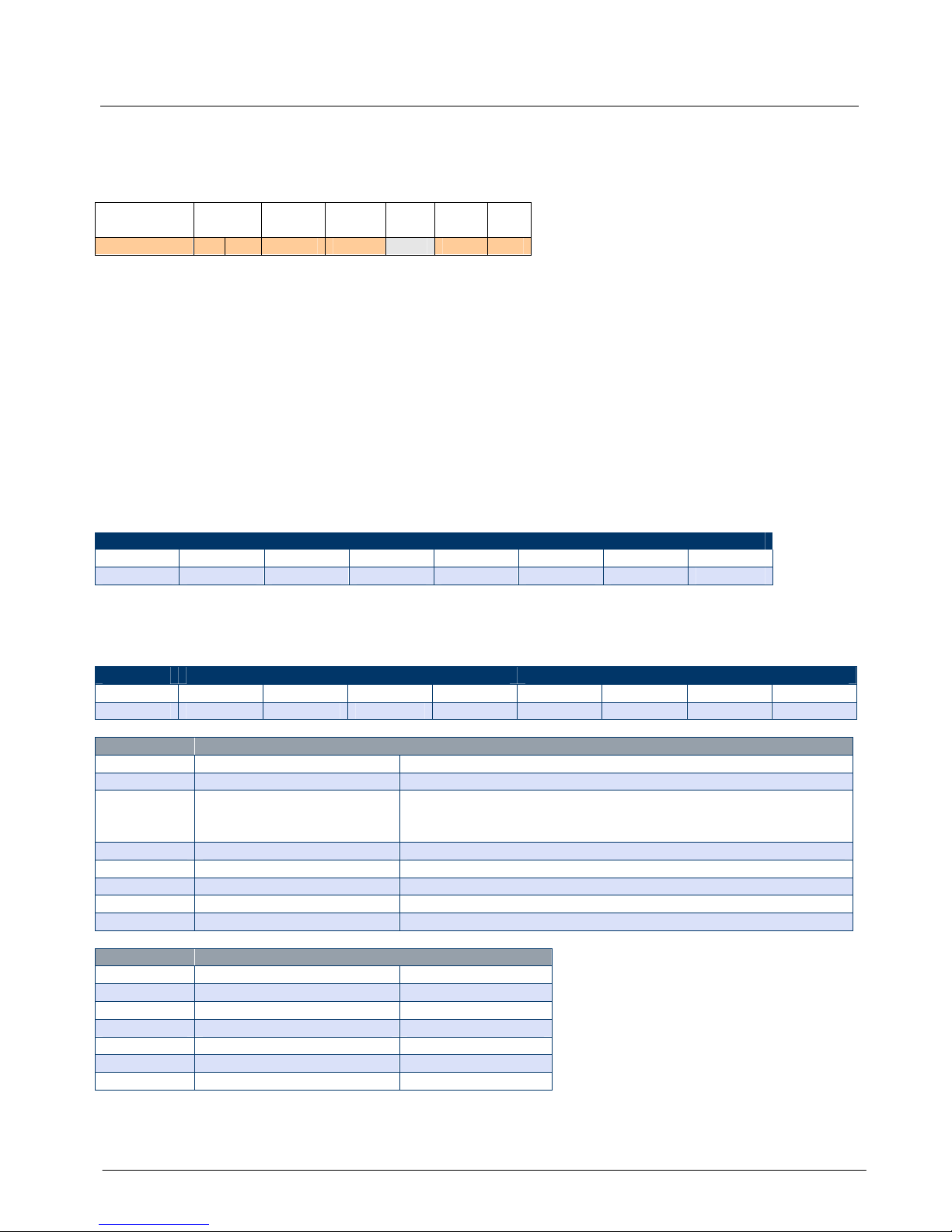
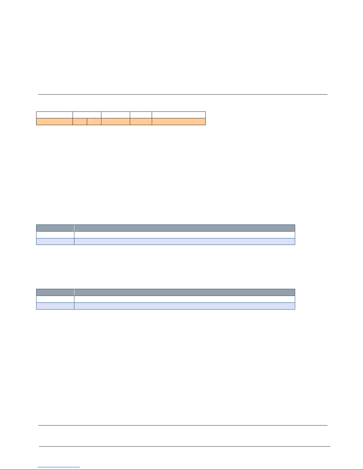
Packet Structure
All packets conform to the following structure. The Data Packet part changes depending on what packet is being
transported.
**Length
**Length
Base
Address
Packet
Type
Data Packet Structure
*CRC1 LSB
*CRC2 MSB
1 Byte
1 Byte
1 Byte
1 Byte
Variable Bytes
1 Byte
1 Byte
* CRC calculated on this part
** Length refers to this sec
tion
This Transport Packet is used to carry the Data Packets into and out of the target device via the base station.
Where:
Length bytes are identical and contain the length of just the Data Packet section.
The CRC bytes are CRC 16 values of all bytes from Length up to and including Data section.
Base Address is the address of the base station used where multiple base stations are deployed. Base station
addresses can range from 1 to 16 and is set by DIP switches on the base station. NOTE: The T24-BSU is fixed
at address 1.
The Packet Type byte defines the packet type thus defining the Data Packet Structure. In received packets
this byte also indicates Error, Low Battery and Broadcast status.
Handling Base Station Data
The packets arriving at the base station serial or USB port are not handshaken. Data may arrive as a partial
packet or many packets may arrive together. Therefore the recommended best practice to handle data is to place
arriving data into a circular buffer and to detect the packets from this buffer by looking for a length byte pair.
Then look forward in the buffer at the CRC position (if the buffer contains enough bytes) and check whether the
CRC is valid. If so you can extract and use the packet. If not then advance the start of the circular buffer until
you find a matching byte pair then check for a valid CRC again.
CRC
The CRC algorithm is identical to that used in Modbus communications and should be calculated for outgoing
packets and checked on incoming packets. The following BASIC example is of a function that will calculate the
CRC of a string and append the two CRC bytes to the end of the string
SUB GenerateCRC16(sTarget AS STRING)

Mantracourt Electronics Limited T24 Technical Manual
7
'reads from buffer
DIM CRC AS LONG
DIM LSB AS INTEGER
DIM C AS LONG
DIM D AS INTEGER
DIM Res(1) AS BYTE
CRC = 65535
FOR C = 1 TO LEN(sTarget)
'xor byte
CRC = CRC XOR ASC(MID$(sTarget, C, 1))
FOR D = 1 TO 8
'get lsb
LSB = (CRC AND 1) = 1
'move right
CRC = INT(CRC / 2)
'if LSB was 1 xor with polynomial
IF LSB THEN CRC = CRC XOR (&HA001&)
NEXT D
NEXT C
sTarget = sTarget & CHR$((CRC AND 255))
sTarget = sTarget & CHR$(INT(CRC / 256))
END SUB
Packet Type Byte
The Packet Type bytes indicates the type of packet and holds information regarding Error, Low Battery and
Broadcast status of received packets.
bit7 bit 6 bit 5 bit 4 bit 3 bit 2 bit 1 bit 0
Error
LoBatt
Broadcast
Pack
et Type
0 0 0 0 0 0 0 0
Bit Function
Error
Bit indicated an error is present.
This is set and reset by the
device which will include this
information in the packet sent to
the module.
LoBatt
Bit indicated a low battery. This
is set and reset by the device
which will include this
information in the packet sent to
the module.
Broadcast
Used to indicate that a routed
packet was broadcast so the
receiver knows not to respond.
Value
Type
Description
3 Data Provider
Used to provide
unrequested data.
5 Read
Read data from a specific
device.
6 Write/command
Write a value or execute a
command to a specific
device
7 Response ACK
Response
- Acknowledged.
May also contain data.
8 Response NAK
Response
- Not
Acknowledged. The
command was not
recognised.
9 Response
Timeout
Response Timed out. A
response was not received
by the device.
10 Response Data
Invalid
Response
– Data invalid.
The device has reported
that the data in a Write was
invalid or out of range.
Mantracourt Electronics Limited T24 Technical Manual
8
Data Packet Structures
The following structures show how the data is defined within the Data Packet Structure of the overall packet.
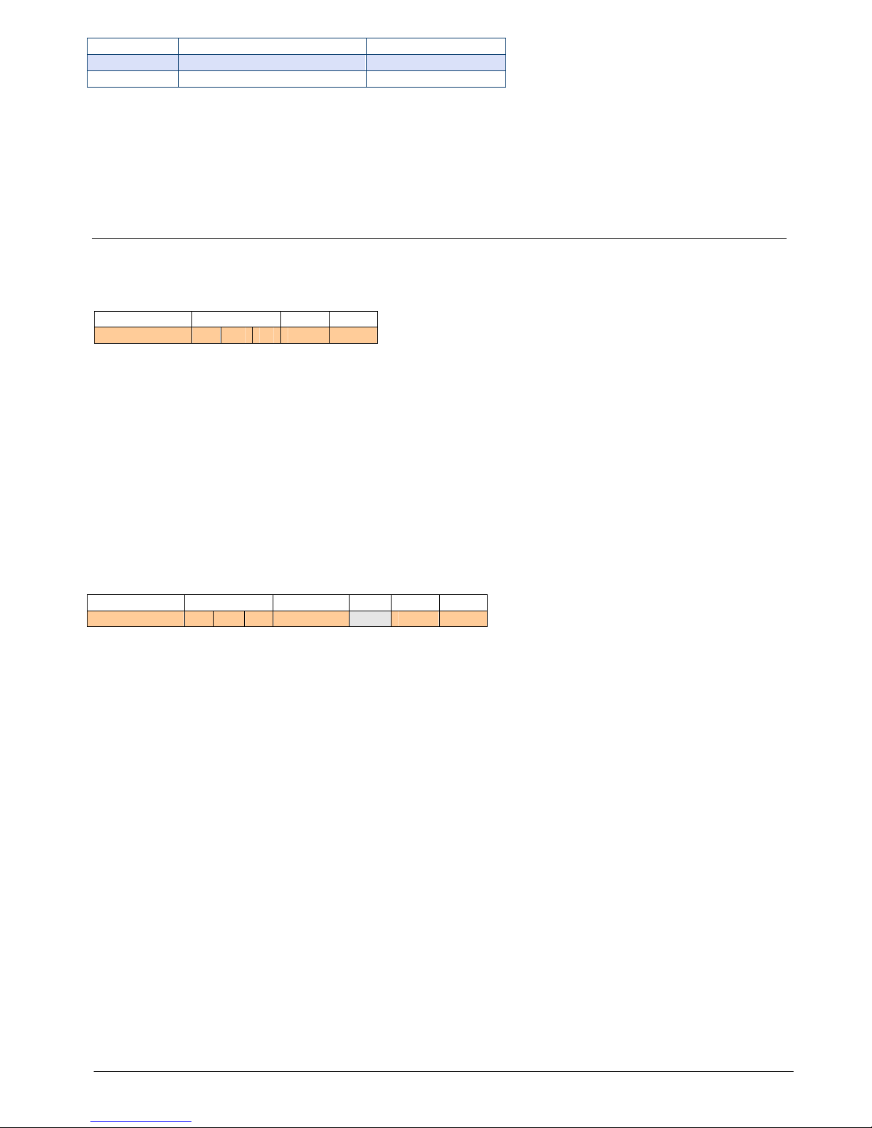
Data Provider
These packets are sent at intervals by some devices and contain data. There is no need to request these packets
as they arrive automatically. If you have multiple base stations and these are within the range of the transmitting
device the packets will arrive from each base station.
Packet Type
Data
Tag
Status
Data
Type
Data RSSI CV
03 00 00 00 00 […] 00 00
Packet Type
This is 0x3 hex (3 decimal) and may have higher bits set which indicate Error, Low Battery and Broadcast.
Data Tag
Every device that transmits Data Provider packets has a configurable 2 byte Data Tag. Devices that consume Data
Provider Packets can be configured to look for specific Data Tags. The reason we use Data Tags and not just rely
on a devices ID for identification is that in a working system multiple devices may be relying on data from a single
device. If that device were ever replaced then its unique ID would change and therefore multiple devices would
have to be reconfigured. By using a Data Tag we only need to change this tag on the replacement device and the
rest of the system will work as required.
Status
The bit values in this byte are used to indicate certain things. Only two bits are allocated a global meaning. The
rest are device specific and you will need to refer to the device manual for clarification.
Status Byte
bit 7 bit 6 bit 5 bit 4 bit 3 bit 2 bit 1 bit0
X X X X X X Integrity
Shunt Cal
Data Type
This byte defines how the data is formatted in this packet and also indicates the best way to represent the data.
Function
Display As
Data Type
Bit 7 6 5 4 3 2 1 0
Sample
0 1 1 1 1 0 0 1
Display As
Type
Description
0 Undefined
1 Numeric
Numeric representati
on based on Data Type
2 Boolean
The data may be in any format but represents a boolean result
where non zero numeric is True and string length > 1 or > 0 is
True
3 Text Can display as ascii text
4 Binary (unprintable)
Unprintable characters
5 Hex Best
represented as hex
6 Bit Map (10110101)
Each bit value should be shown
7 Percent
Numeric or string value has a value 0
- 100
Data Type
Description
Size In Bytes
0 No content/unknown
0
1 UINT8
1
2 UINT16
2
3 INT32
4
4 Float
4
5 String
0-64
6 Binary 0-64
NOTE: See Data Type Formats in Appendix A
The Display As bits should be used where possible as this can help in presenting the data for display purposes.

Mantracourt Electronics Limited T24 Technical Manual
9
Data
This will be of variable length and will depend on the data type.
RSSI
This indicates the signal strength that this packet was received at. See RSSI & CV in Appendix A.
CV
This indicates correlation value which equates to the quality of the signal when this packet was received. See
RSSI & CV in Appendix A.
See Advanced Data Provider Interface in
Read
The read packets are used to read parameters from a remote device or the base station itself. To talk to the base
station just use the base station ID. The module you are communicating with must not be in low power mode and
you will need to know its ID.
Packet Type
To ID
Command
05 00 00 00 00
Packet Type
This is 0x5 hex (5 decimal).
To ID
This is the ID of the device to read from (MSB first).
Command
The command number of the parameter you want to read. You will need to refer to the device manual for this
information.
Write
The write packet is used to write parameter values to a device or execute commands.
You can write any supported data format to any other data format parameter but some formats are not very
suitable. i.e. You can write an INT32 formatted value to a parameter that is just a UINT8 but if the value exceeds
either the target data type limits or any other bounded limits imposed by the device you will receive an
INVALID_DATA response.
When executing a command you do not need any data so it is usual to specify the data type as No Content (zero)
and not include any data.
Packet Type
To ID
Command
Data Type
Data
06 00 00 00 00 00 […]
Packet Type
This is 0x6 hex (6 decimal).
To ID
This is the ID of the device to write to from (MSB first). You can use the broadcast ID here of 0xFFFFFF (255
decimal for each of the To ID bytes) but be careful as this will write the value to all devices on the same channel
and encryption key. You may have mixed device types so command numbers between devices may be different.
Use broadcast with care.
Command
The command number of the parameter you want to write to. You will need to refer to the device manual for this
information.
Data Type
Specify the data type of the data you are sending.
Data types are as follows:
Data Type
Description
Size In Bytes
0 No content/unknown
0
1 UINT8
1
2 UINT16
2
3 INT32
4
Mantracourt Electronics Limited T24 Technical Manual
10
4 Float
4
5 String
0-64
6 Binary
0-64
NOTE: See Data Type Formats in Appendix A
Responses to Read and Write…
The response to either a read or write can be as follows:
Responses to Read: ACK, NAK, TIMEOUT
Responses to Write: ACK, NAK, TIMEOUT, DATAINVALID
ACK
If the ACK response is for a write then it will not contain data:
Packet Type
From ID
RSSI CV
07 00 00 00 00 00
Packet Type
This is 0x7 hex (7 decimal) and may have higher bits set which indicate Error, Low Battery and Broadcast.
From ID
This contains the ID of the device that sent the packet.
RSSI
This indicates the signal strength that this packet was received at. See RSSI & CV in Appendix A.
CV
This indicates correlation value which equates to the quality of the signal when this packet was received. See
RSSI & CV in Appendix A
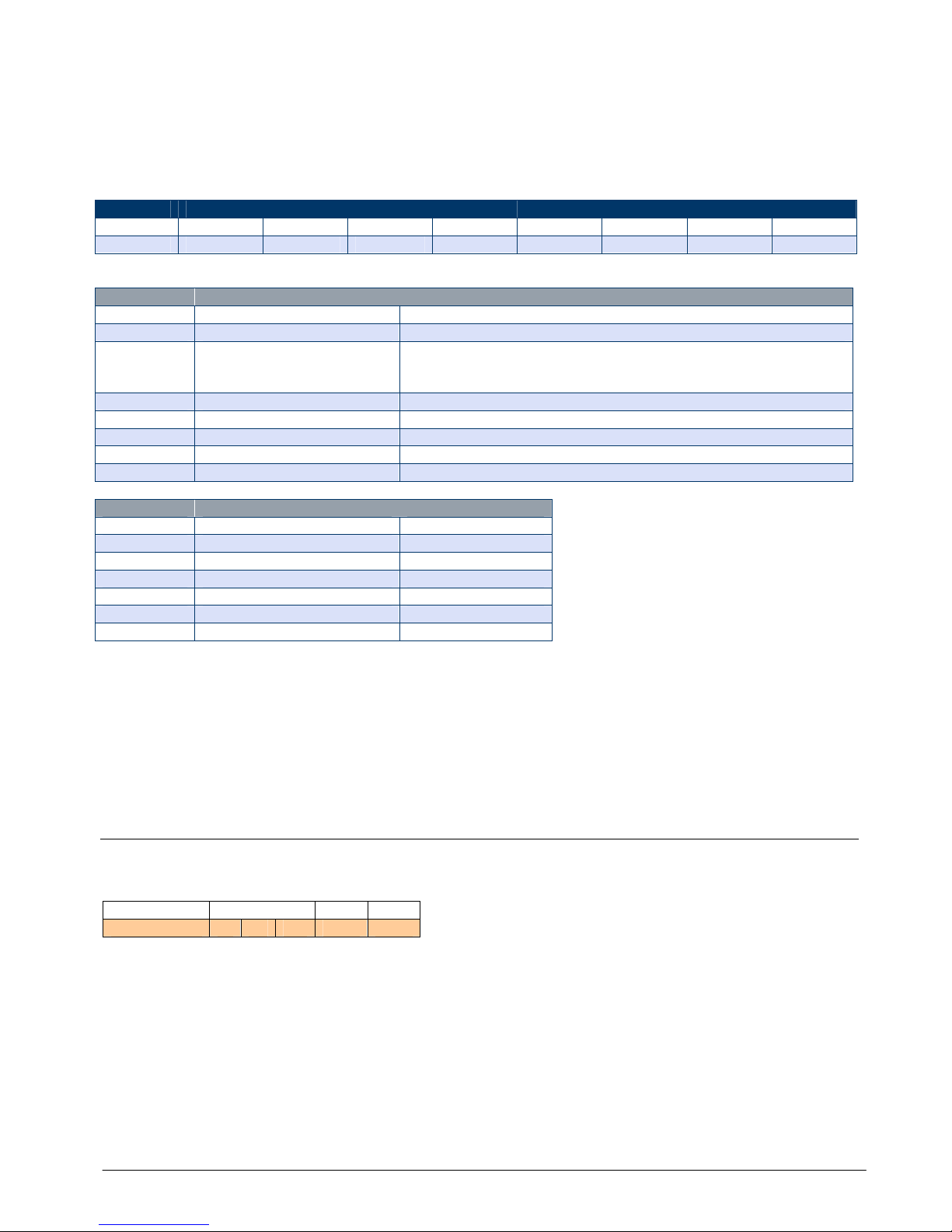
If the ACK is in response to a READ then it will contain data:
Packet Type
From ID
Data Type
Data R
SSI CV
07 00 00 00 00 […] 00 00
Mantracourt Electronics Limited T24 Technical Manual
11
Packet Type
This is 0x7 hex (7 decimal) and may have higher bits set which indicate Error, Low Battery and Broadcast.
From ID
This contains the ID of the device that sent the packet.
Data Type
This byte defines how the data is formatted in this packet and also indicates the best way to represent the data.
Function
Display As
Data Type
Bit 7 6 5 4 3 2 1 0
Sample
0 1 1 1 1 0 0 1
Display As
Type
Description
0 Undefined
1 Numeric
Numeric representation based on Data
Type
2 Boolean
The data may be in any format but represents a boolean result
where non zero numeric is True and string length > 1 or > 0 is
True
3 Text Can display as ASCII text
4 Binary (unprintable)
Unprintable characters
5 Hex Best represented as he
x
6 Bit Map (10110101)
Each bit value should be shown
7 Percent
Numeric or string value has a value 0
- 100
Data Type
Description
Size In Bytes
0 No content/unknown
0
1 UINT8
1
2 UINT16
2
3 INT32
4
4 Float
4
5 String
0-64
6 Binary
0-64
NOTE: See Data Type Formats in Appendix A
RSSI
This indicates the signal strength that this packet was received at. See RSSI & CV in Appendix A.
CV
This indicates correlation value which equates to the quality of the signal when this packet was received. See
RSSI & CV in Appendix A
NAK
This packet is returned if the device receiving the read or write does not recognize the command number.
Packet Type
From ID
RSSI CV
08 00 00 00 00 00
Packet Type
This is 0x8 hex (8 decimal) and may have higher bits set which indicate Error, Low Battery and Broadcast.
Mantracourt Electronics Limited T24 Technical Manual
12
From ID
This contains the ID of the device that sent the packet.
RSSI
This indicates the signal strength that this packet was received at. See RSSI & CV in Appendix A.
CV
This indicates correlation value which equates to the quality of the signal when this packet was received. See
RSSI & CV in Appendix A
TIMEOUT
This packet is returned if the device does not respond.
Packet Type
From ID
RSSI CV
09 00 00 00 00 00
Packet Type
This is 0x9 hex (9 decimal) and may have higher bits set which indicate Error, Low Battery and Broadcast.
From ID
This contains the ID of the device that sent the packet.
RSSI
This indicates the signal strength that this packet was received at. See RSSI & CV in Appendix A.
Note: Some versions of modules may not send the RSSI and CV bytes.
CV
This indicates correlation value which equates to the quality of the signal when this packet was received. See
RSSI & CV in Appendix A
Note: Some versions of modules may not send RSSI and CV bytes.
DATA INVALID
This packet is returned if the device has been written to and the data written is invalid.
Packet Type
From ID
RSSI CV
0A 00 00 00 00 00
Packet Type
This is 0xA hex (10 decimal) and may have higher bits set which indicate Error, Low Battery and Broadcast.
From ID
This contains the ID of the device that sent the packet.
RSSI
This indicates the signal strength that this packet was received at. See RSSI & CV in Appendix A.
CV
This indicates correlation value which equates to the quality of the signal when this packet was received. See
RSSI & CV in Appendix A
Pairing…
Pairing is a method of communicating between two devices so that they configure themselves to one or another's
radio settings and enables them to identify each other by means of ID and default Data Tag.
Additionally the pairing mechanism can pause a device from performing its default behaviour as some devices
operate in a low power mode where they are mostly asleep. This makes communications impossible so the pairing
process stops the low power behaviour.
The pairing process is usually initiated by one device (a handheld for example or PC software using a base station)
and this enters pairing master mode and is ready to pair for a user defined time period.
Mantracourt Electronics Limited T24 Technical Manual
13
Next the other device is put into its pair mode at which time it negotiates with the other device and they will
decide on what to do based on their function. Devices are normally put into pair mode by power cycling them.
Please refer to the device documentation.
For the scope of this document we are concerned with manually controlling the pairing using a base station.
You would use pairing for the following reasons:
You have a device whose communications settings are unknown.
You want to connect to a device that operates in low power mode and is mostly asleep.
The device you want to talk to may have a normal operational function that you want pausing while you
configure it.
You just want to change the communications settings of a device to match it to a base station settings.
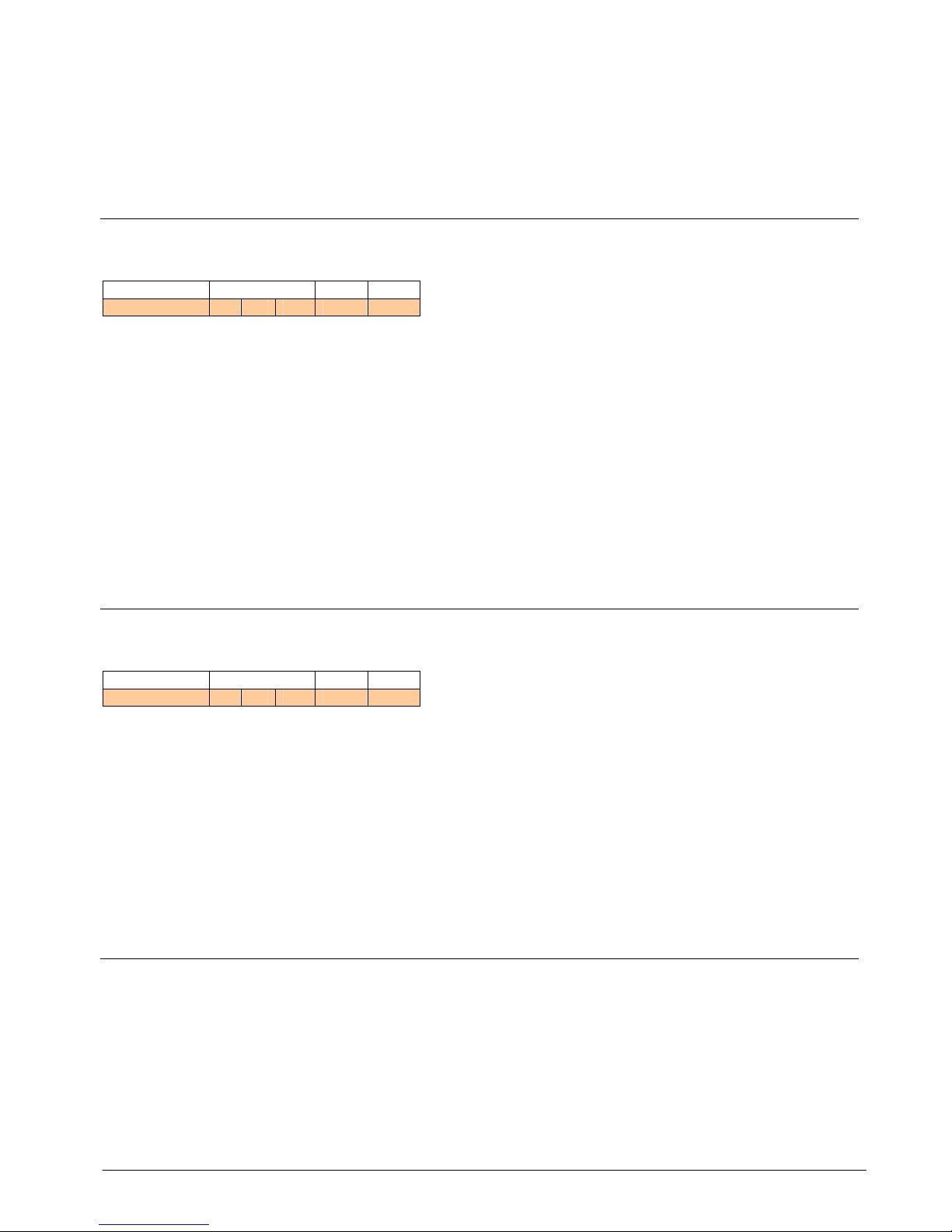
Pair Request
Packet Type
Data Tag
Direction
Config
Duration (optional)
13 00 00 00 00 00
Packet Type
This is 0x13 hex (19 decimal).
Data Tag
You need to supply a Data Tag which may be useable by the device to which you are pairing. Usually from a base
station this is not required and can be set to 0x00, 0x00.
This is present as the same mechanism is used when two devices pair together and in that case they will each
want to give the other their default Data Tag.
Direction
The value of this byte determines whether the remote device radio settings are configured to match the base
station or if the base station is changed to match the remote device. Both the Channel and the encryption key are
matched once pairing has completed.
Value
Meaning
0 The settings in
the remote device are changed to match the base station settings.
1 The base station settings are changed to match the remote device.
Config
The value of this byte determines whether the remote device will enter configuration mode which will inhibit any
low power operation, transmission of data provider packets and the ability to enter deep sleep mode. This mode
is required otherwise communication whilst configuring could be very poor or impossible.
Value
Meaning
0 Do not change operation.
1 Cause th
e device to enter config mode to enable it to be configured.
NOTE: after pairing with a device and using the Config option it is recommended that the device be power cycled
after so that it resumes its normal operation.
.
Duration
The value of this byte determines whether the base station will be in pair mode for the default time of 5 seconds
or whether to use the user defined duration in seconds.
To use the default just omit this byte. If this byte is present its ASCII value will be used to determine how long it
will be in pairing mode.
NOTE: While in pairing mode the base station will not operate as normal.
If the remote device enters its own pair mode (non master) then the communications negotiations will take place
and the device may come out of any low power modes and a response will be sent to the base station.

Mantracourt Electronics Limited T24 Technical Manual
14
Pair Response
This packet will arrive at the base station if another device enters pair mode while the base station is waiting to
pair. Once this packet has arrived the base station will be free to talk to the device. It can also determine the
device ID and Default Data Tag if it needs this information.
Packet
Type
From ID
Data Tag
RSSI CV
14 00 00 00 00 00 00 00
Packet Type
This is 0x14 hex (20 decimal) and may have higher bits set which indicate Error, Low Battery and Broadcast.
From ID
This contains the ID of the device that paired.
Data Tag
This contains the default Data Tag of the paired device.
RSSI
This indicates the signal strength that this packet was received at. See RSSI & CV in Appendix A.
CV
This indicates correlation value which equates to the quality of the signal when this packet was received. See
RSSI & CV in Appendix A
NOTE: After configuration or calibration you should power cycle the paired device to return it to normal
operation.
Mantracourt Electronics Limited T24 Technical Manual
15
T24-BSi and T24-BSu [Base Station]
Overview
These devices are base stations and interface between the radio and a physical interface for a connection to a
PC, PLC or other device.
Addressing
Usually only a single base station is required in a telemetry installation. If a telemetry device is outside the range
of the base station a repeater may be deployed.
Some complex topologies may only be realized by using multiple base stations which may require changes to the
Address switches. See Multipoint Base Station Section.
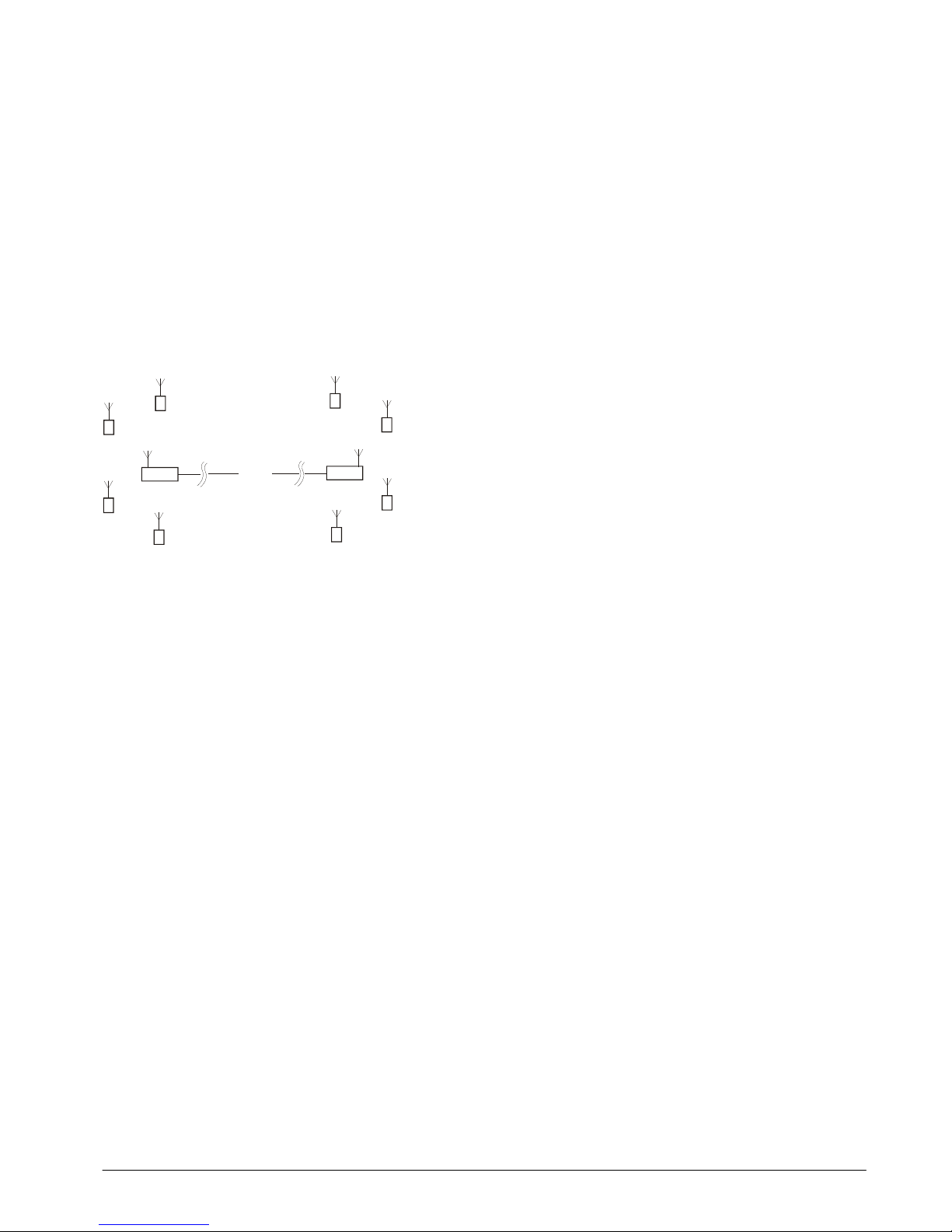
Multipoint Base Stations
Sometimes more than one base station is required in a system. This may simply be a central PC with two base
stations wired off in opposite directions.
Where one base station handles devices on the left and the other those on the right.
Multiple base stations allow flexibility in routing requests from a PC as each time a packet is sent to a base
station it is targeted to a particular base station Address. When a packet arrives back at a PC it contains the
Address of the base station that routed it.
If a base station is the only one connected to a particular serial port then every base station can have Address 1
as the PC will send packets to a particular port to select which base station handles a packet, likewise packets
arriving back at the PC will be identified by the port that they arrive on.
RS232 devices can only be connected one at time anyway but RS485 allows multiple devices on the same bus. This
is where the Addressing is vital as it is this that distinguishes between base stations.
When using USB base stations you may only ever have one T24-BSu connected to a PC at any time. Using T24-BSi
will allow multiple USB base stations to be connected to single PC. Unique Addresses are again required in this
instance.
Note that broadcast packets can be received by multiple base stations so packets may appear duplicated at the
PC end.
It is also possible for the PC to route a packet through all connected base stations by Addressing a packet to
Address 0.
NOTE: Although it is possible to connect multiple USB base stations to a PC the T24drv.dll driver supplied by
Mantracourt only supports one Base Station Addressed as 1.
So when using a T24-BSi which supports USB but also has a DIP switch to allow Address setting the Address must
be set to 1. The T24-BSu devices are manufactured with a fixed Address of 1.

Mantracourt Electronics Limited T24 Technical Manual
16
Connection
The interface can be selected from the DIP switches SW1 as can baudrates for serial interfaces and the Address of
the base station.
SW1 Settings (T24-BSi only)
Switch positions 1 to 4 select the base station Address. This should normally be 1.
1 2 3 4
Address
1 Off Off Off Off
2 On Off Off Off
3 Off On Off Off
4 On On Off Off
5 Off Off On Off
6 On Off On Off
7 Off On On Off
8 On On On Off
9 Off Off Off On
10 On Off Off On
11 Off On Off On
12 On On Off On
13 Off Off On On
14 On Off On On
15 Off On On On
16 On On On On
Switch positions 5 to 7 set whether serial or USB is used. If USB is not selected then the chosen switch settings
control the baudrate for the serial interface. Whether the serial interface is RS485 or RS232 is selected by switch
position 8.
5 6 7
Baudrate / USB
USB Off Off Off
9600
On
Off Off
19200
Off On Off
38400
On On
Off
57600
Off Off On
1152
00 On Off On
230400
Off On On
460800
On On On
NOTE:
A baudrate of 9600 (and in some cases 19200) is not suitable for 2 way communication with remote devices as it is too slow and causes
timeouts. This baudrate has been included to enable the base station to be connected to a 9600 baud device to allow low rate Data
Provider packets to be received.
At any rate below 230400 is may be possible to lose packets at high data rates as the serial cannot keep pace with the radio
transmissions.
If USB is not selected as the interface (Switch positions 5 to 7) then this switch position selects whether the serial
interface is RS232 or RS485.
8
232/485
RS232
Off
RS485
On

Mantracourt Electronics Limited T24 Technical Manual
17
Interfaces
RS232
The RS232 interface uses TX, RX and GND to connect to a PC, PLC etc and uses standard RS232 voltage levels.
Handshaking
None
Data Size
8 bits
Stop Bits
1 bit
Parity
None
The baudrate can be selected by setting the DIP switches stated above. NOTE: the base station will require power
cycling to utilise a baudrate change.
Example connection to a PC 9 way D serial connector.
PC 9 Way D Plug Pin
Signal
Direction
Base Station Connection
3 (TX)
-> RX J6 Pin 2 or J7 Pin 3
2 (RX)
<- TX J6 Pin 3 or J7 Pin 2
5 (Gnd)
GND J6 Pin 4 or J7 Pin 5
8 (CTS)
<- CTS J6 Pin 1 or J7 Pi
n 8
RS485
The RS485 interface (This is a 2 wire 485 interface and will not work with 4 wire 485 buses) uses TX, RX and GND
to connect to a PC, PLC etc and uses standard RS485 voltage levels.
Handshaking
None
Data Size
8 bits
Stop Bits
1 bit
Parity
None
The baudrate can be selected by setting the DIP switches stated above. NOTE: the base station will require power
cycling to utilise a baudrate change.
Example connection
Depending on the RS485 interface or hardware the connections vary and are not standard therefore we can only
show the connections to the base station. You must refer to the user manual regarding your RS485 connection to
ascertain the correct connections.
PC / PLC Connection
Signal
Direction
Base Station Connection
Refer to RS485 Dev
ice User Manual
A J4 Pin 3 or J5 Pin 3
Refer to RS485 Device User Manual
B J4 Pin 4 or J5 Pin 4
Refer to RS485 Device User Manual
GND J4 Pin 5 or J5 Pin 5
NOTE: There are two connectors for RS485, J4 and J5. This is to facilitate easy daisy chaining of devices if
required.
Serial Limitations
• When using RS232 or RS485 you should use the fastest baudrate possible. At lower rates data can be lost
because it can arrive from the radio faster than the base station can send it serially.
• At 9600 baud you will experience communications problems when configuring devices. This baudrate is
too slow for anything other than monitoring data provider packets from devices and even then these
should be at a low rate (around 20 per second ). The slow baudrates are provided to get low rate data
into older systems.
• RS485 is a bus master system and is not ideally suited to full communications with devices when multiple
devices are providing data. This is fine for the normal operation of data acquisition but it is recommended
that only the device to be configured is active during configuration.

Mantracourt Electronics Limited T24 Technical Manual
18
USB
Connection to the base station will be either a captive USB cable (T24-BSu) or a USB socket B for connection using
a standard USB A-B cable (T24-BSi). There is an optional cable assembly for the T24-BSi to provide for a USB
connection while the device is still fitted to the ABS case.
To communicate with the base station the connected device must use the USB HID Device Class and support USB
2.0 full speed interface (12mbits).
The USB connection will also power the base station.
USB Communications
Using the Mantracourt T24drv.dll driver is the easiest way to communicate with the base station. However, if you
want to write your own communications software you will need the following information:
Vendor ID: 6017 (0x1781 hex)
Product ID: 2980 (0xBA4 hex)
Incoming packets are read from report 0 and contain 64 bytes of data. There will always be 64 bytes of even if
there is only a few bytes of valid data. These bytes will need placing into a buffer and your software will need to
detect and extract complete packets.
Outgoing data is written to report 0 and must always contain 64 bytes of data. Any unused bytes should be set to
zero.
Please note that 65 bytes of data are actually sent and received but the first byte indicates the report number so
this is always zero.
Parameter
Value
Vendor ID
0x1781 (6017 decimal)
Product ID
0xBA4 (2980 decimal)
Setup Class
HIDClass
Service Name
HidUsb
Parameter
Value
Connection Information
ConnectionIndex
0x1
CurrentConfigurationValue
0x1
LowSpeed
FALSE
DeviceIsHub
FALSE
DeviceAddress
0x1
NumberOfOpenPipes
0x2
Pipe #0
Endpoint Descriptor
bLength
0x7
bEndpointAddress
0x1 [OUT]
bmAttributes
0x3 (USB_ENDPOINT_TYPE_INTERRUPT)
wMaxPacketSize
0x40
bInterval
0x1
Pipe #1
Endpoint Descriptor
bLength
0x7
bEndpointAddress
0x82 [IN]
bmAttributes
0x3 (USB_ENDPOINT_TYPE_INTERRUPT)
wMaxPacketSize
0x40
bInterval
0x1
Device Descriptor
bLength
0x12
bcdUSB
0x110
bDeviceClass
0x0
bDeviceSubClass
0x0
bDeviceProtocol
0x0
bMaxPacketSize0
0x8
idVendor
0x1781
idProduct
0xBA4
bcdDevice
0x100
iManufacturer
0x1
iProduct
0x2
iSerialNumber
0x3
bNumConfigurations
0x1

Mantracourt Electronics Limited T24 Technical Manual
19
Paramet
er Value
Configuration Descriptor
bLength
0x9
bDescriptorType
USB_CONFIGURATION_DESCRIPTOR_TYPE
wTotalLength
0x29
bNumInterfaces
0x1
iConfiguration
0x0
bmAttributes
0x80 ( Bus_Powered )
MaxPower
0x64
Interface Descriptor
bLength
0x9
bInterfaceNumber
0x0
bAlternateSetting
0x0
bNumEndpoints
0x2
bInterfaceClass
0x3 (Human Interface Device)
bInterfaceSubClass
0x0 (No Subclass)
bInterfaceProtocol
0x0 (None)
iInterface
0x0
Endpoint Descriptor
bLength
0x7
bE
ndpointAddress
0x1 [OUT]
bmAttributes
0x3 (USB_ENDPOINT_TYPE_INTERRUPT)
wMaxPacketSize
0x40
bInterval
0x1
Endpoint Descriptor
bLength
0x7
bEndpointAddress
0x82 [IN]
bmAttributes
0x3 (USB_ENDPOINT_TYPE_INTERRUPT)
wMaxPacketSize
0x40
bInterval
0x1
NOTE: If you do not want to use the Mantracourt supplied communications DLL (T24drv.dll) you may be interested
in the following:
We have successfully tested EasyHID which supplies the mcHID.dll which is a great generic way of connecting to
HID devices. This library is free and was written to ease both the programming of PIC devices and create sample
code for VB, Delphi and Visual C++.
The USB interface has also been successfully used with Windows CE but we do not supply any drivers for this
operating system.
LED Indication
Two LEDS indicate Power/Mode and Activity.
The red LED indicates mode and should flash at a 2Hz rate. If any errors are detected with the radio then the LED
will remain lit.
The green LED flashes once for each packet received or transmitted via radio, USB or serial.

Mantracourt Electronics Limited T24 Technical Manual
20
Communications
To configure the base station you will use the Read and Write mechanisms described in the Data Packet
Structures section to read and write parameters and execute commands.
The base station may also be receiving packets from other devices. These will be Data Provider Packets and these
may arrive at any time.
Parameter List
Parameter
Command
Number
Description
Native Data
Type
Read /
Write
ID 3 Read the unique identifier ID for this device
. (3 bytes)
BINARY 3
byte
R
Channel
11
The radio channel to operate on. (1
-
16) Requires
power cycle or Reset to enable.
UINT8
RW
EncKey
15
The radio encryption key to operate on. Requires
power cycle or Reset to enable. (16 bytes) Not
supported in this release.
BINARY 16
bytes
RW
UseCSMA
18
Select whether to use
Carrier Sense Multiple Access
techniques on transmission.
Value
Description
0 Disabled
The Carrier Sense Multiple Access will be
disabled. NOT RECOMMENDED
1 Enabled
The Carrier Sense Multiple Access will be
enabled.
See Unslotted CSMA/CA in Appendix A
UINT8
RW
Power
12
Set or read the output power level. (0
-
100%)
UINT8
RW
Name
10
Set or read a user defined name. (11 characters)
STRING 11
bytes
RW
WakerDuration
17
Set or read the duration
in milliseconds to wait for a
device to wake. Although WAKE commands are sent to
the target device the base station actually intercepts
this and handles the wake itself. Default = 12000
milliseconds.
UINT16
RW
Save 24 Save any changes made to parameters.
Required
before power cycling or issuing a Reset command.
Requires 200mS recovery time after executing.
Command
Reset
25
Restarts the device and utilises new channel and
encryption keys if those have been changed and saved.
Note after a Reset the device will be asleep.
Command
NOTE: All changes require a SAVE command to enable them to survive through power cycle or RESET command.

Mantracourt Electronics Limited T24 Technical Manual
21
Installation
The base T24-BSi should be mounted horizontally on a wall or ceiling so that the side face containing the PCB
antenna faces the general direction of the target devices.
The T24
-
BSu should also be positioned to present itself to the other radios in
a 'landscape' aspect.
Specification
Parameter
Minimum
Typical
Maximum
Units
Note
s
T24-BSi
External Supply
voltage Range
9 12 32 Volts
T24-BSi, T24
-
BSu
USB
Supply Range
4.875
5
5.125
Volts
As defined by USB 2.0
Specification
Average Operational
Current (T24-BSi)
- TBD 500 mA
USB Bus Powered
Operational Current
100
200
Operati
ng Temperature
Range
-40 - 65
Deg C
Storage Temperature
Range
-40 - 65
Deg C
Reverse polarity
Protection
- -32 Volts
Maximum Supply level

Mantracourt Electronics Limited T24 Technical Manual
22
T24-SA [Strain Acquisition]
Overview
The T24-SA is a strain acquisition module. This allows wireless remote viewing of strain gauge information using
2.4GHz radio.
The T24-SA acquires the weight information from the strain gauge and periodically transmits it. Between
transmissions the device is optionally in a power saving sleep mode to conserve batteries.
Communications
To configure the device you will use the Read and Write mechanisms described in the Data Packet Structures
section to read and write parameters and execute commands.
Parameter List
Parameter
Command
Number
Description
Native
Data
Type
Read /
Write
ID 3 Read the unique identifier ID for this device. (3 bytes)
BINARY 3
bytes
R
Version
53
Read the firmware version.
FLOAT
R
Channel
11
Radio Channel
UINT8
RW
EncKey
15
The radio encryption key to operate on. Requires
power cycle or Reset to enable. Not supported in this
release.
BINARY
16 Bytes
RW
Power
12
Set or read the output power level. (0
-
100%)
UINT8
RW
Name
10
Set or read a user defined name. (11 characters)
STRING
11 Bytes
RW
Model
51
Read the model number of the device.
STRING
11 Bytes
R
WakeChkInt
16
Set or read the interval in milliseconds that a sleeping
device will wake to request a full wake from the base
station. (default 3000)
UINT16
RW
UseCSMA
18
Select whether to use
Carrier Sense Multiple Access
techniques on transmission.
V
alue Description
0 Disabled
The Carrier Sense Multiple Access will be
disabled. NOT RECOMMENDED
1 Enabled
The Carrier Sense Multiple Access will be
enabled.
See Unslotted CSMA/CA in Appendix A
UINT8
RW
BattLevel
69
The voltage measured on the battery.
FLOAT
R
BattLowLevel
110 Set or read the battery voltage at which the low
battery flag will be set in all received packets and in
the Status parameter).
FLOAT
RW
LowPowerMode
75
Defines power save mode.
0 = Awake all the time and transmit at TxInterval.
1 = Sleep. Wake at TXInterval, acquire value, transmit
value, sleep.
UINT8
RW
TxInterval
76
Time Interval between Transmissions. Set mS
INT32
RW
SampleTime
78
Set or read the SampleTime in milliseconds for
acquiring a reading at each TxInterval interval. The
larger the SampleTime the more accurate the reading
but at the expense of battery life. (Default 5)
UINT16
RW
SleepDelay
77
Time period before switching to low power sleep mode
if no StayAwake command or trigger received.
Setting to zero disables.
UINT16
RW
DataTag
119 Set or read the 2 byte Data Tag that is used when
transmitting the weight in a Data Provider Packet.
Note that default value is set to last 2 bytes of ID.
UINT16
RW
NumCalPoints
79
Number of calibration points required. Range 2 to 9
UINT8
RW

Mantracourt Electronics Limited T24 Technical Manual
23
CalPointMVV1
80
The MV/V value of this calibration point.
FLOAT
RW
CalPointMVV2
81
The MV/V value of this calibration point.
FLOAT
RW
CalPointMVV3
82
The MV/V value of this calibration point.
FLOAT
RW
CalPointMVV4
83
The MV/V value of this ca
libration point.
FLOAT
RW
CalPointMVV5
84
The MV/V value of this calibration point.
FLOAT
RW
CalPointMVV6
85
The MV/V value of this calibration point.
FLOAT
RW
CalPointMVV7
86
The MV/V value of this calibration point.
FLOAT
RW
CalPointMVV8
87
The MV/V
value of this calibration point.
FLOAT
RW
CalPointMVV9
88
The MV/V value of this calibration point.
FLOAT
RW
CalPointGain1
89
The gain to apply to the input at this calibration point.
FLOAT
RW
CalPointGain
90
The gain to apply to the input at this calib
ration point.
FLOAT
RW
CalPointGain
91
The gain to apply to the input at this calibration point.
FLOAT
RW
CalPointGain
92
The gain to apply to the input at this calibration point.
FLOAT
RW
CalPointGain
93
The gain to apply to the input at this calibrati
on point.
FLOAT
RW
CalPointGain
94
The gain to apply to the input at this calibration point.
FLOAT
RW
CalPointGain
95
The gain to apply to the input at this calibration point.
FLOAT
RW
CalPointGain
96
The gain to apply to the input at this calibration p
oint.
FLOAT
RW
CalPointGain
97
The gain to apply to the input at this calibration point.
FLOAT
RW
CalPointOffset1
98
The offset to apply to the input at this calibration
point.
FLOAT
RW
CalPointOffset2
99
The offset to apply to the input at this calibra
tion
point.
FLOAT
RW
CalPointOffset3
100 The offset to apply to the input at this calibration
point.
FLOAT
RW
CalPointOffset4
101 The offset to apply to the input at this calibration
point.
FLOAT
RW
CalPointOffset5
102 The offset to apply to the input a
t this calibration
point.
FLOAT
RW
CalPointOffset6
103 The offset to apply to the input at this calibration
point.
FLOAT
RW
CalPointOffset7
104 The offset to apply to the input at this calibration
point.
FLOAT
RW
CalPointOffset8
105 The offset to apply
to the input at this calibration
point.
FLOAT
RW
CalPointOffset9
106 The offset to apply to the input at this calibration
point.
FLOAT
RW
Value
72
Reads the calibrated weight.
FLOAT
R
Counts
70
Raw A/D counts
INT32
R
mVV 71 Factory calibrated mV/V
FLOA
T R
DigitalOut
108 Read or set the digital output state.
Value
Definition
0 Turn digital output off
1 Turn digital output on
2 Make digital output mirror
the LED state (V1.05 and
later)
UINT8
RW
ShuntCal
109 Read or set the
shuntcal
state.
Value
Definition
0 Turn shuntcal off
1 Turn shuntcal on
UINT8
RW
Status
74
Live status where the bit values indicate status. The
following table shows the decimal bit values and their
meaning.
Bit Value
Definition
1 STATUS_SHUNT_CAL
2 STATUS_INPUT_I
NTEGRITY
4 Reserved
8 Reserved
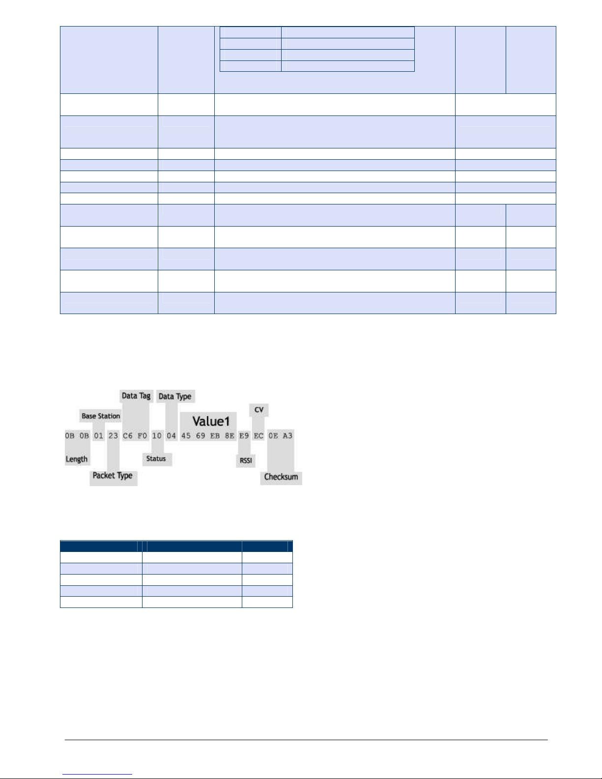
Mantracourt Electronics Limited T24 Technical Manual
24
16 STATUS_POWER_UP
32 STATUS_BATT_LOW
64 STATUS_DIGITAL_INPUT
128 STATUS_DIGITAL_OUTPUT
Reset
54
Restarts the device and utilises new channel and
encryption keys if those have been changed and saved.
Command
S
ave 55 Save any changes made to parameters. Required
before power cycling or issuing a Reset command.
Requires 500mS recovery time after executing.
Command
Wake
50
Wake the module from sleep
Command
Sleep
56
Sends the
module
to
Sleep
Command
Pause
57 Stops the output streaming to allow configuration
Command
Resume
59
Streaming continues.
Command
StayAwake
58
No function other than to reset SleepDelay timer
Command
SleepTrigger
120 Enter Data Tag to watch for that will trigger sleep
mode
UINT16
RW
Pa
useTrigger
121 Enter Data Tag to watch for that will trigger pause
mode
UINT16
RW
ResumeTrigger
123 Enter Data Tag to watch for that will trigger resume
mode
UINT16
RW
StayAwakeTrigger
122 Enter Data Tag to watch for that will reset SleepDelay
timer.
UIN
T16 RW
DoSystemZeroTrigger
125 Enter Data Tag to watch for that will reset SleepDelay
timer.
UINT16
RW
NOTE: All changes require a SAVE command to enable them to survive through power cycle or RESET command.
Data Provider Format
At every TXInterval a Data Provider packet is transmitted that holds 1 value in FLOAT format (See Appendix A).
Measurement Resolution
The noise free resolution is dependant on the Sample Time (SampleTime)
SampleTime (mS)
Noise Free Resolution
Ratio
> 0 15.5 bits
1:50,0
00
> 9 16 bits
1:65,000
> 49 17.25 bits
1:150,000
> 99 18 bits
1:250,000
> 999
18.75 bits
1:400,000
Power Supply
See Appendix B – Acquisition Module Power Supply
Battery Life
See Appendix B – Acquisition Module Battery Life – Strain Gauge Input

Mantracourt Electronics Limited T24 Technical Manual
25
Installation
Antennas
See Appendix B – Antenna Installation

Mantracourt Electronics Limited T24 Technical Manual
26
T24-VA [0-10V Voltage Acquisition]
Overview
The T24-VA is a voltage acquisition module. This allows wireless remote viewing of voltage information using
2.4GHz radio.
The T24-VA acquires the voltage value (scales and linearises it to user defined specification) and periodically
transmits it. Between transmissions the device is optionally in a power saving sleep mode to conserve batteries.
Communications
To configure the device you will use the Read and Write mechanisms described in the Data Packet Structures
section to read and write parameters and execute commands.
Parameter List
Parameter
Command
Number
Description
Native
Data
Type
Read /
Write
ID 3 Read the unique identifier
ID for this device. (3 bytes)
BINARY 3
bytes
R
Version
53
Read the firmware version.
FLOAT
R
Channel
11
Radio Channel
UINT8
RW
EncKey
15
The radio encryption key to operate on. Requires
power cycle or Reset to enable. Not supported in this
release.
BINA
RY
16 Bytes
RW
Power
12
Set or read the output power level. (0
-
100%)
UINT8
RW
Name
10
Set or read a user defined name. (11 characters)
STRING
11 Bytes
RW
Model
51
Read the model number of the device.
STRING
11 Bytes
R
WakeChkInt
16
Set or read the inte
rval in milliseconds that a sleeping
device will wake to request a full wake from the base
station. (default 3000)
UINT16
RW
UseCSMA
18
Select whether to use
Carrier Sense Multiple Access
techniques on transmission.
Value
Description
0 Disabled
The Carrier Sense Multiple Access will be
disabled. NOT RECOMMENDED
1 Enabled
The Carrier Sense Multiple Access will be
enabled.
See Unslotted CSMA/CA in Appendix A
UINT8
RW
BattLevel
69
The voltage measured on the battery.
FLOAT
R
BattLowLevel
110 Set or re
ad the battery voltage at which the low
battery flag will be set in all received packets and in
the Status parameter).
FLOAT
RW
LowPowerMode
75
Defines power save mode.
0 = Awake all the time and transmit at TxInterval.
1 = Sleep. Wake at TXInterval, acquire value, transmit
value, sleep.
UINT8
RW
TxInterval
76
Time Interval between Transmissions. Set mS
INT32
RW
SampleTime
78
Set or read the SampleTime in milliseconds for
acquiring a reading at each TxInterval interval. The
larger the SampleTime the more accurate the reading
but at the expense of battery life. (Default 5)
UINT16
RW
SleepDelay
77
Time period before switching to low power sleep mode
if no StayAwake command or trigger received.
Setting to zero disables.
UINT16
RW
DataTag
119 Set or read t
he 2 byte Data Tag that is used when
transmitting the weight in a Data Provider Packet.
Note that default value is set to last 2 bytes of ID.
UINT16
RW
NumCalPoints
79
Number of calibration points required. Range 2 to 9
UINT8
RW

Mantracourt Electronics Limited T24 Technical Manual
27
CalPoint1
80
The % full s
cale value of this calibration point.
FLOAT
RW
CalPoint2
81
The % full scale value of this calibration point.
FLOAT
RW
CalPoint3
82
The % full scale value of this calibration point.
FLOAT
RW
CalPoint4
83
The % full scale value of this calibration point.
FLOAT
RW
CalPoint5
84
The % full scale value of this calibration point.
FLOAT
RW
CalPoint6
85
The % full scale value of this calibration point.
FLOAT
RW
CalPoint7
86
The % full scale value of this calibration point.
FLOAT
RW
CalPoint8
87
The % full sc
ale value of this calibration point.
FLOAT
RW
CalPoint9
88
The % full scale value of this calibration point.
FLOAT
RW
CalPointGain1
89
The gain to apply to the input at this calibration point.
FLOAT
RW
CalPointGain
90
The gain to apply to the input at t
his calibration point.
FLOAT
RW
CalPointGain
91
The gain to apply to the input at this calibration point.
FLOAT
RW
CalPointGain
92
The gain to apply to the input at this calibration point.
FLOAT
RW
CalPointGain
93
The gain to apply to the input at this
calibration point.
FLOAT
RW
CalPointGain
94
The gain to apply to the input at this calibration point.
FLOAT
RW
CalPointGain
95
The gain to apply to the input at this calibration point.
FLOAT
RW
CalPointGain
96
The gain to apply to the input at this cali
bration point.
FLOAT
RW
CalPointGain
97
The gain to apply to the input at this calibration point.
FLOAT
RW
CalPointOffset1
98
The offset to apply to the input at this calibration
point.
FLOAT
RW
CalPointOffset2
99
The offset to apply to the input at thi
s calibration
point.
FLOAT
RW
CalPointOffset3
100 The offset to apply to the input at this calibration
point.
FLOAT
RW
CalPointOffset4
101 The offset to apply to the input at this calibration
point.
FLOAT
RW
CalPointOffset5
102 The offset to apply to th
e input at this calibration
point.
FLOAT
RW
CalPointOffset6
103 The offset to apply to the input at this calibration
point.
FLOAT
RW
CalPointOffset7
104 The offset to apply to the input at this calibration
point.
FLOAT
RW
CalPointOffset8
105 The offset
to apply to the input at this calibration
point.
FLOAT
RW
CalPointOffset9
106 The offset to apply to the input at this calibration
point.
FLOAT
RW
Value
72
Reads the user calibrated output.
FLOAT
R
Counts
70
Raw A/D counts
INT32
R
PFS 71 Factory calibr
ated percent full scale (0=0V, 100=10V)
FLOAT
R
DigitalOut
108 Read or set the digital output state.
Value
Definition
0 Turn digital output off
1 Turn digital output on
2 Make digital output mirror the LED
state (V1.05 and later)
FLOAT
RW
Status
74
Live status where the bit values indicate status. The
following table shows the decimal bit values and their
meaning.
Bit Value
Definition
1 STATUS_SHUNT_CAL
2 STATUS_INPUT_INTEGRITY
4 Reserved
8 Reserved
16 STATUS_POWER_UP
32 STATUS_BATT_LOW
64 STATUS_DIGITAL_INPUT
128 STATUS_DIGITAL_OUTPUT
Reset
54
Restarts the device and utilises new channel and
encryption keys if those have been changed and saved.
Command
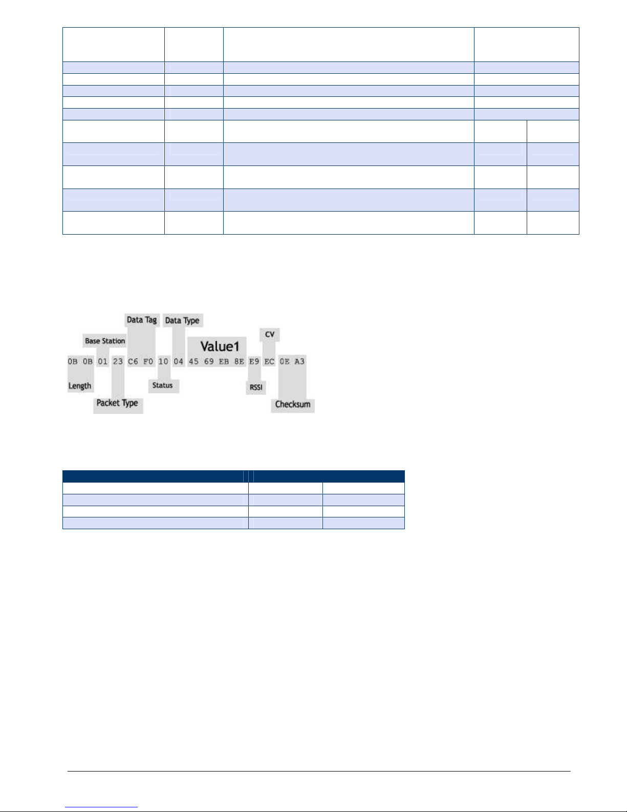
Mantracourt Electronics Limited T24 Technical Manual
28
Save 55 Save any changes made to parameters. Required
before power cycling or issuing a Reset command.
Requires 500mS recovery time after executing.
Command
Wake
50
Wake the module from sleep
Command
Sleep
56
Sends the
module to
Sleep
Command
Pause
57
Stops the output streaming to allow configuration
Command
Resume
59
Streamin
g continues.
Command
StayAwake
58
No function other than to reset SleepDelay timer
Command
SleepTrigger
120 Enter Data Tag to watch for that will trigger sleep
mode
UINT16
RW
PauseTrigger
121 Enter Data Tag to watch for that will trigger pause
mode
UIN
T16 RW
ResumeTrigger
123 Enter Data Tag to watch for that will trigger resume
mode
UINT16
RW
StayAwakeTrigger
122 Enter Data Tag to watch for that will reset SleepDelay
timer.
UINT16
RW
DoSystemZeroTrigger
125 Enter Data Tag to watch for that will reset
SleepDelay
timer.
UINT16
RW
NOTE: All changes require a SAVE command to enable them to survive through power cycle or RESET command.
Data Provider Format
At every TXInterval a Data Provider packet is transmitted that holds 1 value in FLOAT format (See Appendix A).
Measurement Resolution
The noise free resolution is dependant on the Sample Time (SampleTime)
Typical
Units
Noise free where Sample Time < 10mS
5,000 / 12.25
Resolution / Bits
Noise free where Sample Time < 100mS
8,000 / 13.0
Reso
lution / Bits
Noise free where Sample Time < 1000mS
11,000 / 13.5
Resolution / Bits
Noise free where Sample Time > 1000mS
15,000 / 13.75
Resolution / Bits
Power Supply
See Appendix B – Acquisition Module Power Supply
Battery Life
See Appendix B – Acquisition Module Battery Life – Non Strain Gauge Input
Antennas
See Appendix B – Antenna Installation

Mantracourt Electronics Limited T24 Technical Manual
29
T24-IA [4-20mA Current Acquisition]
Overview
The T24-IA is a current acquisition module. This allows wireless remote viewing of current information using
2.4GHz radio.
The T24-IA acquires the current value (scales and linearises it to user defined specification) and periodically
transmits it. Between transmissions the device is optionally in a power saving sleep mode to conserve batteries.
Communications
To configure the device you will use the Read and Write mechanisms described in the Data Packet Structures
section to read and write parameters and execute commands.
Parameter List
Parameter
Command
Number
Description
Native
Data
Type
Read /
Write
ID 3 Read the unique identifier ID for this device. (3 bytes)
BINARY 3
bytes
R
Version
53
Read the firmware version.
FLOAT
R
Channel
11
Radio Channel
UINT8
RW
EncKey
15
The radio encryption key to operate on. Requires
power cycle or Reset to enable. Not supported in this
release.
BINARY
16 Bytes
RW
Power
12
Set or read the output power level. (0
-
100%)
UINT8
RW
Name
10
Set or read a user defined name. (11 characters)
STRING
11 Bytes
RW
Model
51
Read the model number of the device.
STRING
11 Bytes
R
WakeC
hkInt
16
Set or read the interval in milliseconds that a sleeping
device will wake to request a full wake from the base
station. (default 3000)
UINT16
RW
UseCSMA
18
Select whether to use
Carrier Sense Multiple Access
techniques on transmission.
Value
Description
0 Disabled
The Carrier Sense Multiple Access will be
disabled. NOT RECOMMENDED
1 Enabled
The Carrier Sense Multiple Access will be
enabled.
See Unslotted CSMA/CA in Appendix A
UINT8
RW
BattLevel
69
The voltage measured on the battery.
FLOAT
R
BattLowLevel
110 Set or read the battery voltage at which the low
battery flag will be set in all received packets and in
the Status parameter).
FLOAT
RW
LowPowerMode
75
Defines power save mode.
0 = Awake all the time and transmit at TxInterval.
1 = Sleep. Wake at TXInterval, acquire value, transmit
value, sleep.
UINT8
RW
TxInterval
76
Time Interval between Transmissions. Set mS
INT32
RW
SampleTime
78
Set or read the SampleTime in milliseconds for
acquiring a reading at each TxInterval interval. The
larger the SampleTime the more accurate the reading
but at the expense of battery life. (Default 5)
UINT16
RW
SleepDelay
77
Time period before switching to low power sleep mode
if no StayAwake command or trigger received.
Setting to zero disables.
UINT16
RW
DataTag
119 Set or read the 2 byte Data Tag that is used when
transmitting the weight in a Data Provider Packet.
Note that default value is set to last 2 bytes of ID.
UINT16
RW
NumCalPoints
79
Number of calibration points required. Range 2 to 9
UINT8
RW
 Loading...