

Mantracourt T24-PR1 User Manual

T24
-
PR1
Printer
User Manual
www.mantracourt.co.uk

1
Introduction / Overview..................................................................................................... 2
Communications Overview ................................................................................................ 2
Configuration Overview .................................................................................................... 2
Getting Started ............................................................................................................. 3
Connecting Power ........................................................................................................ 3
Configuration .................................................................................................................. 3
Installation .................................................................................................................. 3
T24 Toolkit ................................................................................................................ 3
T24-BSu Base Station .................................................................................................... 3
T24 Toolkit .................................................................................................................. 4
General Pages ............................................................................................................ 4
Setup Base Station Communications ................................................................................ 4
Home .................................................................................................................... 5
Analyser ................................................................................................................ 6
Information ............................................................................................................ 7
Channel and Encryption .............................................................................................. 8
Save and Restore ...................................................................................................... 9
Input Settings ........................................................................................................ 10
Output Settings ...................................................................................................... 12
Output Scaling ....................................................................................................... 14
Output Design ........................................................................................................ 15
Zero Settings ......................................................................................................... 17
Zero Settings Advanced ............................................................................................ 18
Configuration Examples ................................................................................................... 19
Print Gross Sum of 2 Devices to Printer ............................................................................... 19
Customer Ticket from Handheld Device ............................................................................... 19
Printer Operation and Maintenance .................................................................................... 21
Paper Roll Fitting and Replacement ................................................................................... 21
Buttons and Indicators ................................................................................................... 21
Specifications ............................................................................................................... 22
General Radio ............................................................................................................. 22
T24-PR1 .................................................................................................................... 22
Printer ...................................................................................................................... 22
Mechanical Dimensions .................................................................................................. 23
Installation ................................................................................................................... 24
Overview ................................................................................................................... 24
Approvals .................................................................................................................... 25
CE ........................................................................................................................... 25
FCC ......................................................................................................................... 25
Industry Canada ........................................................................................................... 26
OEM / Reseller Marking and Documentation Requirements ........................................................ 26
FCC ......................................................................................................................... 26
IC ............................................................................................................................ 26
CE ........................................................................................................................... 26
Declaration of Conformity ................................................................................................ 28
Worldwide Regional Approvals ........................................................................................... 29
Important Note ......................................................................................................... 29
Warranty ..................................................................................................................... 29
Mantracourt Electronics Limited T24-PR1 User Manual

2
Introduction / Overview
ID Identifies each device
Data Tag
Identifies each Data Provider message
The T24-PR1 is a thermal printer module that can print a 57mm wide ticket which can include data from up to
8 devices and optionally sum them. The printout can be triggered from the arrival of data from a specific
device or alternatively by a handheld device which can also optionally supply the data value to print.
NOTE: Print triggering from an external button/switch option will be made available on future releases of the T24-PR1.
The actual printed output can be designed by the user using multiple lines which can include free text or
tokens which can represent real data. i.e. <V1> would be decoded as the value from input 1 when the print is
triggered or <TV> would reference the Trigger Value from an external handheld for example.
Communications Overview
The T24 range of telemetry devices each have a factory set unique ID.
Data is shared between devices using Data Provider messages. A device generates these messages which can
then be used by many other devices simultaneously.
These messages ( or packets ) of information contain a single value of data and each is identified by a Data
Tag.
The Data Tag should be unique for each message.
Each device has a unique ID that is factory set. This is represented as a 6 character hexadecimal
number consisting of the digits 0 to 9 and the letters A to F.
I.e.
FFD3BE
A Data Tag consists of a 4 character hexadecimal number consisting of the digits 0 to 9 and the
letters A to F. The Data Tag can be changed by the user but the factory default is to match the
last 4 characters of the device ID.
I.e. An acquisition device of ID
When a device consumes data (i.e. a handheld displaying data from an acquisition device) all it is doing is
listening to all of the Data Provider messages and selecting the one it wants to use. It then extracts the data
and displays it.
Some devices that use Data Provider messages also need to know the ID of the device providing the data. This
is necessary if that device needs to specifically wake the data providing device as opposed to using a broadcast
wake that will wake all devices on the same channel and using the same encryption key.
Pairing offers an automated method of hooking a provider and consumer of data together. However, some
devices may require you to manually enter Data Tag and ID information so it would be beneficial to the user to
understand the above mechanism.
FFC12B
would have a default Data Tag of
C12B
.
Configuration Overview
Once it has been determined how many devices are feeding data to this device you need to record the Data Tag
that each of these devices are attaching to their Data Provider packets.
These Data Tags are then entered into the ValueDataTagx parameters. Once the rate at which this data arrives
is known you can enter the Timeoutx values.
Leave unused ValueDataTagx parameters with a value of zero to ensure that they are not checked for timeouts
and do not contribute to gross or net sums.
When a data provider packet arrives whose Data Tag matches one of those in the ValueDataTagx parameters
the value it contains will be placed in the Valuex parameter.
If data does not arrive from a device within the Timeoutx period then any reference to either the individual Vx
tokens or one of the summing tokens will result in ------ rather than a numeric value.
The actual serial output can now be constructed using Line1 to Line25 (In the toolkit these are hidden and the
user simply creates the ticket on screen). These parameters take text into which you can insert tokens. When a
Mantracourt Electronics Limited T24-PR1 User Manual

3
'Print' is generated these lines are parsed and tokens replaced with the values they represent and the resulting
data sent to the serial port.
A 'Print' is generated by either issuing a DoPrint command, activating the switch input when SwitchMode is set
to zero or by receiving a Data Provider packet whose Data Tag matches the PrintDataTag parameter.
When a 'Print' is executed each of the parameters Line1 to Line 25 will be parsed. Every token will be evaluated
and replaced with the live value.
Getting Started
To get the T24-PR1 to print live data we need an external device. This can be one or more acquisition devices
or a handheld device which is already paired with an acquisition device.
To attach acquisition devices to the T24-PR1 we must first ensure that the appropriate devices are transmitting
their values at a suitable rate such as the default of 3 per second. Then we can configure the module to use
the data from these devices.
Configuration must be done with the T24 Toolkit software and a base station.
Connecting Power
You will need to connect a power supply to the T24-PR1 for it to operate and to enable configuration using a
base station and the appropriate toolkit software.
Power is supplied via a 2.5mm DC plug which plugs into, and locks with, a 2.5mm socket on the side of the
module. Voltage range is 9 to 36 Volts dc and requires approximately a one Ampere (1A) capable supply.
The tip of the connector is positive.
Configuration
This section explains how to install software and connect the required devices together. Please note that you
will need the T24 Toolkit software and a T24-BS base station to allow your computer to communicate with T24
telemetry devices.
Installation
T24 Toolkit
To configure the devices we must use the T24 Toolkit software application. This can be downloaded from our
web site or may be shipped with your products.
Install this on a PC or laptop.
Run setup.exe and follow the prompts to install the software.
T24-BSu Base Station
If you have a USB version of the base station (T24-BSu) then you just need to plug this into a USB socket on your
PC. If you are using an alternative base station then please refer to the appropriate manual.
Mantracourt Electronics Limited T24-PR1 User Manual
4
T24 Toolkit
The T24 Toolkit provides a means of simple configuration of the T24-PR1 and associated acquisition module
along with useful tools to aid integration. Calibration of the acquisition modules is also provided.
Run the T24 Toolkit software application.
General Pages
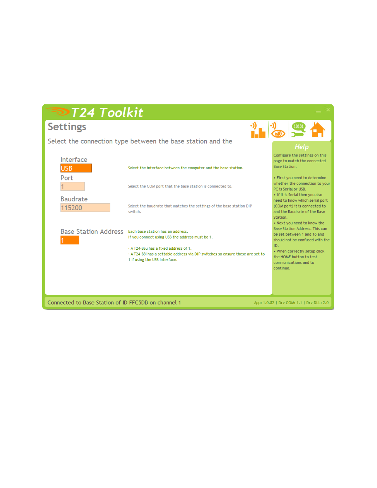
Setup Base Station Communications
Select USB as the interface and select 1 as the Base Station Address.
In the toolkit all items that can be changed by the user are coloured orange.
To change a value just click on the relevant orange item. You will then be presented with a new dialog window
allowing you to change the value.
This may use a slider, text box or list to allow your new value to be entered.
Click the Home button to attempt communications with the base station.
If no communications can be established the toolkit will remain on this page. You will need to check that the
base station is powered and that it is connected to the converter correctly.
Mantracourt Electronics Limited T24-PR1 User Manual

5
Home
We now have successful communications with the base station so we can now pair with our device or we can
select the Spectrum Analyser mode or Data Provider Monitor mode.
Pairing Procedure
• Remove power from the T24-PR1 module.
• Click the Pair button on the toolkit.
• You now have 10 seconds to re-apply power to the T24-PR module.
If you connect successfully the toolkit will change to the Information page.
If the pairing fails try again.
NOTE: The act of Pairing with the toolkit will not change the radio configuration settings of the connected
device. The settings will only change if you change them yourself within the toolkit.
Mantracourt Electronics Limited T24-PR1 User Manual
6
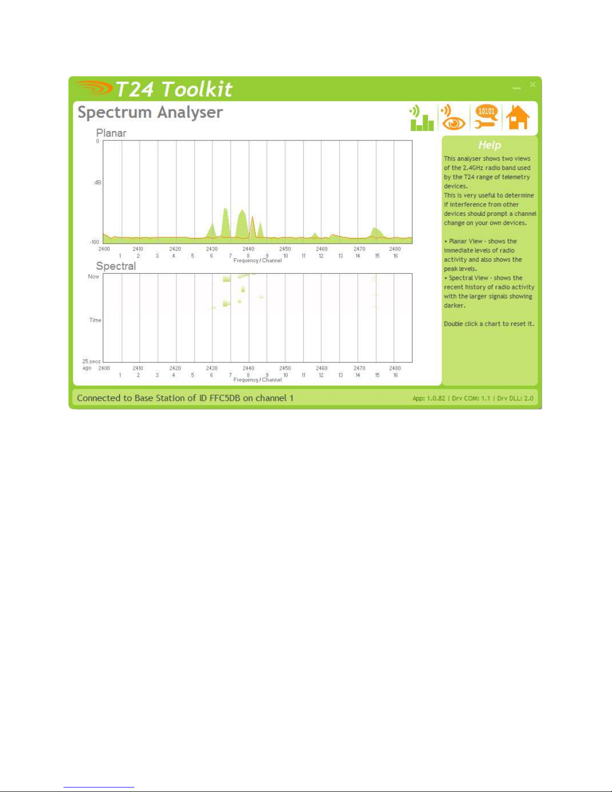
Analyser
The analyser page is provided as a tool and will not normally be needed unless you plan to change channels and
want to find the best channel to select, or to diagnose poor communications issues.
This page shows the radio signal levels detected across all the channels available to the T24 series of devices.
Using this tool may help in detecting noisy areas and allow you to decide on which channels you may want to
use.
The above charts show the traffic from a Wi-Fi network and it can be seen to be operating over channels 6 to 9
and it would be best (though not essential) to avoid using these channels.
Mantracourt Electronics Limited T24-PR1 User Manual
7
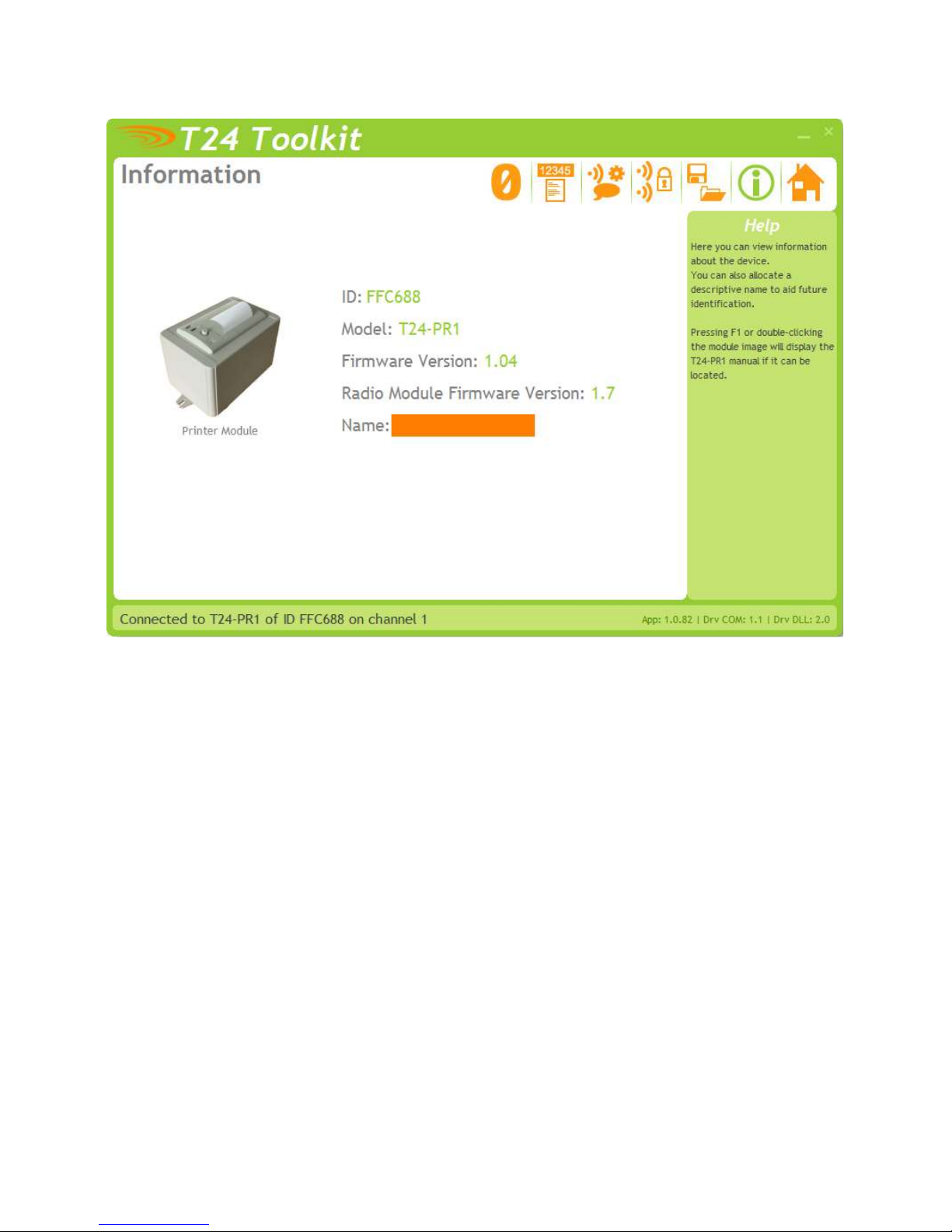
Information
Items you c
an change
:
Name
You can enter a short descript
ive name
(11 characters)
which may help you recognise this
This page shows you information about the connected device.
device in the future.
Mantracourt Electronics Limited T24-PR1 User Manual

8
Channel and Encryption
Items you can change
:
Channel
Select a channel between 1 and 16. The default is channel 1. You can use the
Encryption Key
Only devices with identical encryption keys can communicate. You can isolate
Here you can change the channel and encryption key for the module.
NOTE: Early acquisition module do not yet utilise the encryption keys so these should be left at all zeros.
Spectrum Analyser mode to determine a good clean channel to use.
NOTE: Channel 16 is used to negotiate pairing so avoid this channel if possible.
groups of devices on the same channel or just use the key to ensure the data
cannot be read by somebody else.
Mantracourt Electronics Limited T24-PR1 User Manual
 Loading...