

Mantracourt T24-ANTD, T24-ANTB, T24-ANTC, T24-BC1, T24-ANTE User Manual
...

1
Introduction / Overview .......................................................................................................................................... 16
Navigating This Manual .......................................................................................................................................... 17
Product Quick Locator ............................................................................................................................................. 17
T24 Telemetry Basic Principles............................................................................................................................... 18
Transmitters & Receivers ...................................................................................................................................................................... 18
Transmitters ........................................................................................................................................................................................... 18
Receivers ................................................................................................................................................................................................. 18
Radio Channel and Group Key ........................................................................................................................................................... 18
Radio Channel ...................................................................................................................................................................................... 18
Group Key ............................................................................................................................................................................................... 18
Configuring Multiple Modules to Use the Same Radio Settings .......................................................................................... 19
ID and Data Tags ...................................................................................................................................................................................... 19
Transmitter Module Modes of Operation ...................................................................................................................................... 19
Normal ..................................................................................................................................................................................................... 19
Configuration ........................................................................................................................................................................................ 19
Sleep ......................................................................................................................................................................................................... 19
Transmitter Module Sleep Delay Settings ...................................................................................................................................... 20
Pairing .......................................................................................................................................................................................................... 20
Pairing From T24 Toolkit .................................................................................................................................................................. 20
Pairing From a Receiver Module ................................................................................................................................................... 20
Soft Pairing ................................................................................................................................................................................................. 21
Configuring an Attached Base Station ............................................................................................................................................ 21
Asynchronous Operation and Logging ........................................................................................................................................... 21
Bandwidth ................................................................................................................................................................................................... 22
Repeaters and Repeater Subgroups ................................................................................................................................................ 22
T24 Toolkit ................................................................................................................................................................ 23
Common Toolkit Pages ........................................................................................................................................... 24
Setup Base Station Communications ............................................................................................................................................... 24
Analyser ....................................................................................................................................................................................................... 25
Channel Monitor ...................................................................................................................................................................................... 26
Home ............................................................................................................................................................................................................ 28
Connecting to a remote module ................................................................................................................................................... 28
Connecting to the attached base station module ................................................................................................................. 29
Manual Connection ............................................................................................................................................................................ 29
Information ................................................................................................................................................................................................. 30
Battery and Radio Levels ....................................................................................................................................................................... 31
Battery and Radio Levels Advanced ................................................................................................................................................. 32
Radio Settings ........................................................................................................................................................................................... 33
Radio Settings Advanced ...................................................................................................................................................................... 34
Save and Restore ..................................................................................................................................................................................... 35
Transmitter Modules ............................................................................................................................................... 36
T24-ACM-SA, T24-ACMi-SA, T24-ACMm-SA, T24-SAe, T24-SAi .......................................................................................... 36
Overview ................................................................................................................................................................................................. 36
Order Codes .......................................................................................................................................................................................... 36
T24-SAe .............................................................................................................................................................................................. 36
T24-SAi ................................................................................................................................................................................................ 36
T24-ACM-SA ..................................................................................................................................................................................... 36
T24-ACMi-SA .................................................................................................................................................................................... 36
T24-ACMm-SA ................................................................................................................................................................................. 36
Connections ........................................................................................................................................................................................... 37
T24-SAe, T24-SAi ............................................................................................................................................................................
37
Power .............................................................................................................................................................................................. 37
Sensor ............................................................................................................................................................................................. 37
T24-ACM-SA ..................................................................................................................................................................................... 38
Power .............................................................................................................................................................................................. 38
Sensor ............................................................................................................................................................................................. 38
Mantracourt Electronics Limited T24 Telemetry User Manual

2
T24-ACMi-SA .................................................................................................................................................................................... 39
Power .............................................................................................................................................................................................. 39
Sensor ............................................................................................................................................................................................. 39
T24-ACMm-SA ................................................................................................................................................................................. 40
Power .............................................................................................................................................................................................. 40
Connecting T24-BB1 ............................................................................................................................................................ 40
Sensor ............................................................................................................................................................................................. 40
Using Completion Resistors ................................................................................................................................................... 41
Full Bridge ............................................................................................................................................................................... 41
Half Bridge ............................................................................................................................................................................. 41
Quarter Bridge ........................................................................................................................................................................ 41
Strain Element in Compression ................................................................................................................................... 41
Strain Element in Tension .............................................................................................................................................. 41
Shield Connections (All Enclosures) .................................................................................................................................... 42
Configuration ........................................................................................................................................................................................ 43
Data Rates and Quality ................................................................................................................................................................. 43
Calibration ......................................................................................................................................................................................... 45
Calibration by Certificate ............................................................................................................................................................. 47
Calibration Advanced .................................................................................................................................................................... 48
Advanced Settings.......................................................................................................................................................................... 49
Enclosure & Mounting ...................................................................................................................................................................... 50
T24-SAe, T24-SAi ............................................................................................................................................................................ 50
T24-ACM-SA ..................................................................................................................................................................................... 50
T24-ACMi-SA .................................................................................................................................................................................... 50
T24-ACMm-SA ................................................................................................................................................................................. 50
Antennas ................................................................................................................................................................................................. 50
T24-SAi ................................................................................................................................................................................................ 50
T24-SAe .............................................................................................................................................................................................. 50
T24-ACM-SA, T24-ACMi-SA, T24-ACMm-SA ...................................................................................................................... 50
Specification .......................................................................................................................................................................................... 51
Radio Range ...................................................................................................................................................................................... 52
T24-ACM-SAf, T24-ACMi-SAf, T24-ACMm-SAf, T24-SAfe, T24-SAfi .................................................................................. 53
Overview ................................................................................................................................................................................................. 53
Order Codes .......................................................................................................................................................................................... 53
T24-SAfe ............................................................................................................................................................................................. 53
T24-SAfi .............................................................................................................................................................................................. 53
T24-ACM-SAf ................................................................................................................................................................................... 53
T24-ACMi-SAf .................................................................................................................................................................................. 53
T24-ACMm-SAf ............................................................................................................................................................................... 53
Connections ........................................................................................................................................................................................... 54
T24-SAfe, T24-SAfi ......................................................................................................................................................................... 54
Power .............................................................................................................................................................................................. 54
Sensor ............................................................................................................................................................................................. 54
T24-ACM-SAf ................................................................................................................................................................................... 55
Power .............................................................................................................................................................................................. 55
Sensor ............................................................................................................................................................................................. 55
T24-ACMi-SAf .................................................................................................................................................................................. 56
Power .............................................................................................................................................................................................. 56
Sensor ............................................................................................................................................................................................. 56
T24-ACMm-SAf ............................................................................................................................................................................... 57
Power .............................................................................................................................................................................................. 57
Connecting T24-BB1 ................................................................................................................................................................. 57
Sensor ............................................................................................................................................................................................. 57
Using Completion Resistors ................................................................................................................................................... 58
Full Bridge ............................................................................................................................................................................... 58
Half Bridge ............................................................................................................................................................................. 58
Mantracourt Electronics Limited T24 Telemetry User Manual

3
Quarter Bridge ........................................................................................................................................................................ 58
High Reference .................................................................................................................................................................. 58
Low Reference .................................................................................................................................................................... 58
Shield Connections (All Enclosures) .................................................................................................................................... 59
C
onfiguration ........................................................................................................................................................................................ 60
Battery Life ......................................................................................................................................................................................... 60
Zero Settings .................................................................................................................................................................................... 62
Data Provider Monitor .................................................................................................................................................................. 63
Advanced Settings.......................................................................................................................................................................... 64
Enclosure & Mounting ...................................................................................................................................................................... 65
T24-SAfe, T24-SAfi ......................................................................................................................................................................... 65
T24-ACM-SAf ................................................................................................................................................................................... 65
T24-ACMi-SAf .................................................................................................................................................................................. 65
T24-ACMm-SAf ............................................................................................................................................................................... 65
Antennas ................................................................................................................................................................................................. 65
T24-SAfi .............................................................................................................................................................................................. 65
T24-SAfe ............................................................................................................................................................................................. 65
T24-ACM-SAf, T24-ACMi-SAf, T24-ACMm-SAf .................................................................................................................. 65
Specification .......................................................................................................................................................................................... 66
Radio Range ...................................................................................................................................................................................... 66
T24-ACM-VA, T24-ACMi-VA, T24-ACMm-VA, T24-VAe, T24-VAi ........................................................................................ 67
Overview ................................................................................................................................................................................................. 67
Order Codes .......................................................................................................................................................................................... 67
T24-VAe .............................................................................................................................................................................................. 67
T24-VAi ............................................................................................................................................................................................... 67
T24-ACM-VA .................................................................................................................................................................................... 67
T24-ACMi-VA ................................................................................................................................................................................... 67
T24-ACMm-VA ................................................................................................................................................................................ 67
Connections ........................................................................................................................................................................................... 68
T24-VAe, T24-VAi ........................................................................................................................................................................... 68
Power .............................................................................................................................................................................................. 68
Sensor ............................................................................................................................................................................................. 68
T24-ACM-VA .................................................................................................................................................................................... 69
Power .............................................................................................................................................................................................. 69
Sensor ............................................................................................................................................................................................. 69
T24-ACMi-VA ................................................................................................................................................................................... 70
Power .............................................................................................................................................................................................. 70
Sensor ............................................................................................................................................................................................. 70
T24-ACMm-VA ................................................................................................................................................................................ 71
Power .............................................................................................................................................................................................. 71
Connecting T24-BB1 ............................................................................................................................................................ 71
Sensor ............................................................................................................................................................................................. 71
Shield Connections (All Enclosures) ........................................................................................................................................ 72
Configuration ........................................................................................................................................................................................ 73
Data Rates and Quality ................................................................................................................................................................. 73
Calibration ......................................................................................................................................................................................... 75
Calibration by Certificate ............................................................................................................................................................. 77
Calibration Advanced .................................................................................................................................................................... 78
Advanced Settings.......................................................................................................................................................................... 79
Enclosure & Mounting ...................................................................................................................................................................... 80
T24-VAe, T24-VAi ........................................................................................................................................................................... 80
T24-ACM-VA .................................................................................................................................................................................... 80
T24-ACMi-VA ................................................................................................................................................................................... 80
T24-ACMm-VA ................................................................................................................................................................................ 80
Antennas ................................................................................................................................................................................................. 81
T24-VAi ............................................................................................................................................................................................... 81
Mantracourt Electronics Limited T24 Telemetry User Manual

4
T24-VAe .............................................................................................................................................................................................. 81
T24-ACM-VA, T24-ACMi-VA, T24-ACMm-VA ..................................................................................................................... 81
Specification .......................................................................................................................................................................................... 82
Radio Range ...................................................................................................................................................................................... 82
T24-ACM-IA, T24-ACMi-IA, T24-ACMm-IA, T24-IAe, T24-IAi ................................................................................................ 83
Overview ................................................................................................................................................................................................. 83
Order Codes .......................................................................................................................................................................................... 83
T24-IAe................................................................................................................................................................................................ 83
T24-IAi ................................................................................................................................................................................................. 83
T24-ACM-IA ...................................................................................................................................................................................... 83
T24-ACMi-IA ..................................................................................................................................................................................... 83
T24-ACMm-IA .................................................................................................................................................................................. 83
Connections ........................................................................................................................................................................................... 84
T24-IAe, T24-IAi ............................................................................................................................................................................... 84
Power .............................................................................................................................................................................................. 84
Sensor ............................................................................................................................................................................................. 84
T24-ACM-IA ...................................................................................................................................................................................... 84
Power .............................................................................................................................................................................................. 84
Sensor ............................................................................................................................................................................................. 85
T24-ACMi-IA ..................................................................................................................................................................................... 86
Power .............................................................................................................................................................................................. 86
Sensor ............................................................................................................................................................................................. 86
T24-ACMm-IA .................................................................................................................................................................................. 87
Power .............................................................................................................................................................................................. 87
Connecting T24-BB1 ............................................................................................................................................................ 87
Sensor ............................................................................................................................................................................................. 87
Shield Connections (All Enclosures) ........................................................................................................................................ 88
Configuration ........................................................................................................................................................................................ 89
Data Rates and Quality ................................................................................................................................................................. 89
Calibration ......................................................................................................................................................................................... 91
Calibration by Certificate ............................................................................................................................................................. 93
Calibration Advanced .................................................................................................................................................................... 94
Advanced Settings.......................................................................................................................................................................... 95
Enclosure & Mounting ...................................................................................................................................................................... 96
T24-IAe, T24-IAi ............................................................................................................................................................................... 96
T24-ACM-IA ...................................................................................................................................................................................... 96
T24-ACMi-IA ..................................................................................................................................................................................... 96
T24-ACMm-IA .................................................................................................................................................................................. 96
Antennas ................................................................................................................................................................................................. 97
T24-IAi ................................................................................................................................................................................................. 97
T24-IAe................................................................................................................................................................................................ 97
T24-ACM-IA, T24-ACMi-IA, T24-ACMm-IA .......................................................................................................................... 97
Specification .......................................................................................................................................................................................... 98
Radio Range ...................................................................................................................................................................................... 98
T24-ACM-TA, T24-ACMi-TA, T24-ACMm-TA, T24-TAe, T24-TAi .......................................................................................... 99
Overview ................................................................................................................................................................................................. 99
Order Codes .......................................................................................................................................................................................... 99
T24-TAe .............................................................................................................................................................................................. 99
T24-TAi ................................................................................................................................................................................................ 99
T24-ACM-TA ..................................................................................................................................................................................... 99
T24-ACMi-TA .................................................................................................................................................................................... 99
T24-ACMm-TA ................................................................................................................................................................................. 99
Connections ......................................................................................................................................................................................... 100
T24-TAe, T24-TAi .......................................................................................................................................................................... 100
Power ............................................................................................................................................................................................ 100
Sensor ........................................................................................................................................................................................... 100
Mantracourt Electronics Limited T24 Telemetry User Manual

5
2 Wire ....................................................................................................................................................................................... 100
3 Wire ....................................................................................................................................................................................... 100
4 Wire ....................................................................................................................................................................................... 101
T24-ACM-TA ................................................................................................................................................................................... 101
Power ............................................................................................................................................................................................ 101
Sensor ........................................................................................................................................................................................... 101
T24-ACMi-TA .................................................................................................................................................................................. 102
Power ............................................................................................................................................................................................ 102
Sensor ........................................................................................................................................................................................... 102
T24-ACMm-TA ............................................................................................................................................................................... 102
Power ............................................................................................................................................................................................ 102
Connecting T24-BB1 .......................................................................................................................................................... 103
Sensor ........................................................................................................................................................................................... 103
Shield Connections (All Enclosures) ...................................................................................................................................... 104
Configuration ...................................................................................................................................................................................... 105
Data Rates and Quality ............................................................................................................................................................... 105
Calibration ....................................................................................................................................................................................... 107
Advanced Settings........................................................................................................................................................................ 108
Enclosure & Mounting .................................................................................................................................................................... 109
T24-TAe, T24-TAi .......................................................................................................................................................................... 109
T24-ACM-TA ................................................................................................................................................................................... 109
T24-ACMi-TA .................................................................................................................................................................................. 109
T24-ACMm-TA ............................................................................................................................................................................... 109
Antennas ............................................................................................................................................................................................... 109
T24-TAi .............................................................................................................................................................................................. 109
T24-TAe ............................................................................................................................................................................................ 109
T24-ACM-TA, T24-ACMi-TA, T24-ACMm-TA .................................................................................................................... 109
Specification ........................................................................................................................................................................................ 110
Radio Range .................................................................................................................................................................................... 110
T24-ACM-RA, T24-ACMi-RA, T24-ACMm-RA, T24-RAe, T24RAi ........................................................................................ 111
Overview ............................................................................................................................................................................................... 111
Order Codes ........................................................................................................................................................................................ 111
T24-RAe ............................................................................................................................................................................................ 111
T24-RAi ............................................................................................................................................................................................. 111
T24-ACM-RA................................................................................................................................................................................... 111
T24-ACMi-RA ................................................................................................................................................................................. 111
T24-ACMm-RA............................................................................................................................................................................... 111
Connections ......................................................................................................................................................................................... 112
T24-RAe, T24-RAi.......................................................................................................................................................................... 112
Power ............................................................................................................................................................................................ 112
Sensor ........................................................................................................................................................................................... 112
T24-ACM-RA................................................................................................................................................................................... 112
Power ............................................................................................................................................................................................ 112
Sensor ........................................................................................................................................................................................... 113
T24-ACMi-RA ................................................................................................................................................................................. 114
Power ............................................................................................................................................................................................ 114
Sensor ........................................................................................................................................................................................... 114
T24-ACMm-RA............................................................................................................................................................................... 115
Power ............................................................................................................................................................................................ 115
Connecting T24-BB1 .......................................................................................................................................................... 115
Sensor ........................................................................................................................................................................................... 115
Shield Connections (All Enclosures) ...................................................................................................................................... 116
Configuration ...................................................................................................................................................................................... 117
Data Rates and Quality ............................................................................................................................................................... 117
Input / Output Configuration .................................................................................................................................................. 119
Calibration by Certificate ........................................................................................................................................................... 121
Mantracourt Electronics Limited T24 Telemetry User Manual

6
Calibration Advanced .................................................................................................................................................................. 122
Advanced Settings........................................................................................................................................................................ 124
Enclosure & Mounting .................................................................................................................................................................... 125
T24-RAe, T24-RAi.......................................................................................................................................................................... 125
T24-ACM-RA................................................................................................................................................................................... 125
T24-ACMi-RA ................................................................................................................................................................................. 125
T24-ACMm-RA............................................................................................................................................................................... 125
Antennas ............................................................................................................................................................................................... 126
T24-RAi ............................................................................................................................................................................................. 126
T24-RAe ............................................................................................................................................................................................ 126
T24-ACM-RA, T24-ACMi-RA, T24-ACMm-RA ................................................................................................................... 126
Specification ........................................................................................................................................................................................ 127
Radio Range .................................................................................................................................................................................... 127
T24-ACM-PA, T24-ACMi-PA, T24-ACMm-PA, T24-PAe, T24-PAi ....................................................................................... 128
Overview ............................................................................................................................................................................................... 128
Order Codes ........................................................................................................................................................................................ 128
T24-PAe ............................................................................................................................................................................................ 128
T24-PAi ............................................................................................................................................................................................. 128
T24-ACM-PA ................................................................................................................................................................................... 128
T24-ACMi-PA .................................................................................................................................................................................. 128
T24-ACMm-PA ............................................................................................................................................................................... 128
Connections ......................................................................................................................................................................................... 129
T24-PAe, T24-PAi .......................................................................................................................................................................... 129
Power ............................................................................................................................................................................................ 129
Sensor ........................................................................................................................................................................................... 129
Relay & Volt Free Contact ................................................................................................................................................ 130
Voltage Source ..................................................................................................................................................................... 130
NP
N Open Collector........................................................................................................................................................... 130
PNP Open Collector 5V Powered Sensor ................................................................................................................... 130
T24-ACM-PA ................................................................................................................................................................................... 131
Power ............................................................................................................................................................................................ 131
Sensor ........................................................................................................................................................................................... 131
T24-ACMi-PA .................................................................................................................................................................................. 132
Power ............................................................................................................................................................................................ 132
Sensor ........................................................................................................................................................................................... 132
T24-ACMm-PA ............................................................................................................................................................................... 133
Power ............................................................................................................................................................................................ 133
Connecting T24-BB1 .......................................................................................................................................................... 133
Sensor ........................................................................................................................................................................................... 133
Shield Connections (All Enclosures) ...................................................................................................................................... 134
Configuration ...................................................................................................................................................................................... 135
Data Rates and Quality ............................................................................................................................................................... 135
Input / Output Configuration .................................................................................................................................................. 137
Advanced I/O ................................................................................................................................................................................. 138
Custom Output Type .............................................................................................................................................................. 138
Advanced Settings........................................................................................................................................................................ 139
Enclosure & Mounting .................................................................................................................................................................... 140
T24-PAe, T24-PAi .......................................................................................................................................................................... 140
T24-ACM-PA ................................................................................................................................................................................... 140
T24-ACMi-PA .................................................................................................................................................................................. 140
T24-ACMm-PA ............................................................................................................................................................................... 140
Antennas ............................................................................................................................................................................................... 141
T24-PAi ............................................................................................................................................................................................. 141
T24-PAe ............................................................................................................................................................................................ 141
T24-ACM-PA, T24-ACMi-PA, T24-ACMm-PA .................................................................................................................... 141
Specification ........................................................................................................................................................................................ 142
Mantracourt Electronics Limited T24 Telemetry User Manual

7
Radio Range .................................................................................................................................................................................... 142
T24-WSS .................................................................................................................................................................................................... 143
Overview ............................................................................................................................................................................................... 143
Order Codes ........................................................................................................................................................................................ 143
T24-WSS ........................................................................................................................................................................................... 143
Connections ......................................................................................................................................................................................... 144
Power ............................................................................................................................................................................................ 144
Configuration ...................................................................................................................................................................................... 144
Data Rates and Quality ............................................................................................................................................................... 145
Units ................................................................................................................................................................................................... 147
Advanced Settings........................................................................................................................................................................ 148
Enclosure & Mounting .................................................................................................................................................................... 149
Antennas ............................................................................................................................................................................................... 149
Specification ........................................................................................................................................................................................ 150
Radio Range .................................................................................................................................................................................... 150
Receiver Modules ................................................................................................................................................... 151
T24-HS ........................................................................................................................................................................................................ 151
Overview ............................................................................................................................................................................................... 151
Order Codes ........................................................................................................................................................................................ 151
T24-HS .......................................................................................................................................................................................... 151
Connections ......................................................................................................................................................................................... 151
Power ............................................................................................................................................................................................ 151
Quick Start............................................................................................................................................................................................ 152
Connecting Power ........................................................................................................................................................................ 152
T24-HS .......................................................................................................................................................................................... 152
Transmitter Module ................................................................................................................................................................ 152
Pairing ............................................................................................................................................................................................... 152
Operation ......................................................................................................................................................................................... 153
Keys ............................................................................................................................................................................................... 153
Modes ........................................................................................................................................................................................... 153
Indicators ..................................................................................................................................................................................... 153
Errors ............................................................................................................................................................................................. 153
Configuration ...................................................................................................................................................................................... 155
Zero Settings .................................................................................................................................................................................. 156
Display Format ............................................................................................................................................................................... 158
Display Format Advanced Settings ........................................................................................................................................ 159
Advanced Settings........................................................................................................................................................................ 160
Enclosure & Mounting .................................................................................................................................................................... 162
Antennas ............................................................................................................................................................................................... 162
Specification ........................................................................................................................................................................................ 163
Radio Range .................................................................................................................................................................................... 163
T24-HA ....................................................................................................................................................................................................... 164
Overview ............................................................................................................................................................................................... 164
Order Codes ........................................................................................................................................................................................ 164
T24-HA ......................................................................................................................................................................................... 164
Connections ......................................................................................................................................................................................... 164
Power ............................................................................................................................................................................................ 164
Operation ............................................................................................................................................................................................. 165
Item Mode ....................................................................................................................................................................................... 165
Keys ............................................................................................................................................................................................... 165
Result Mode .................................................................................................................................................................................... 166
Keys when viewing Result ................................................................................................................................................ 166
Keys when viewing an individual item ........................................................................................................................ 166
All Modes ......................................................................................................................................................................................... 168
Indicators ................................................................................................................................................................................ 168
Errors ........................................................................................................................................................................................ 168
Mantracourt Electronics Limited T24 Telemetry User Manual

8
Other Functions.................................................................................................................................................................... 168
Configuration ...................................................................................................................................................................................... 169
Mode and Communications ..................................................................................................................................................... 169
Prompts ............................................................................................................................................................................................ 171
Zero Settings .................................................................................................................................................................................. 172
Zero Settings Advanced ............................................................................................................................................................. 174
Display Format ............................................................................................................................................................................... 175
Display Format Advanced Settings ........................................................................................................................................ 177
Advanced Settings........................................................................................................................................................................ 178
Enclosure & Mounting .................................................................................................................................................................... 180
Antennas ............................................................................................................................................................................................... 180
Specification ........................................................................................................................................................................................ 181
Radio Range .................................................................................................................................................................................... 181
T24-HR ....................................................................................................................................................................................................... 182
Overview ............................................................................................................................................................................................... 182
Order Codes ........................................................................................................................................................................................ 182
T24-HR ......................................................................................................................................................................................... 182
Connections ......................................................................................................................................................................................... 182
Power ............................................................................................................................................................................................ 182
Operation ............................................................................................................................................................................................. 183
View readings ................................................................................................................................................................................. 183
Keys .................................................................................................................................................................................................... 183
Indicators ......................................................................................................................................................................................... 183
Errors .................................................................................................................................................................................................. 184
Special Modes ................................................................................................................................................................................ 184
Transmitter Module Configuration ........................................................................................................................................ 185
Configuration ...................................................................................................................................................................................... 186
Display Format ............................................................................................................................................................................... 186
Display Format Advanced Settings ........................................................................................................................................ 188
Settings ............................................................................................................................................................................................. 189
Example Installation Scenarios ..................................................................................................................................................... 190
Scenario 1 – 200 transmitter modules are spaced at 1 meter intervals along a bridge. .................................. 190
Scenario 2 – The operator has 3 rooms to monitor........................................................................................................ 190
Scenario 3 – 500 pallets are stored in a warehouse. ...................................................................................................... 190
Enclosure & Mounting .................................................................................................................................................................... 191
Antennas ............................................................................................................................................................................................... 191
Specification ........................................................................................................................................................................................ 192
Radio Range .................................................................................................................................................................................... 192
T24-AO1, T24-AO1i ............................................................................................................................................................................... 193
Overview ............................................................................................................................................................................................... 193
Order Codes ........................................................................................................................................................................................ 193
T24-AO1 ........................................................................................................................................................................................... 193
T24-AO1i .......................................................................................................................................................................................... 193
Connections ......................................................................................................................................................................................... 194
Power ................................................................................................................................................................................................. 194
T24-AO1....................................................................................................................................................................................... 194
T24-AO1i ..................................................................................................................................................................................... 194
Connections and Indicators ...................................................................................................................................................... 195
T24-AO1....................................................................................................................................................................................... 195
T24-AO1i ..................................................................................................................................................................................... 195
Output Range Setting ................................................................................................................................................................. 195
LED Indicators ................................................................................................................................................................................ 196
Configuration ...................................................................................................................................................................................... 197
T24 Toolkit ....................................................................................................................................................................................... 197
Input / Output ................................................................................................................................................................................ 198
Alarm Settings ................................................................................................................................................................................ 200
Mantracourt Electronics Limited T24 Telemetry User Manual

9
Zero Settings .................................................................................................................................................................................. 202
Advanced Settings........................................................................................................................................................................ 203
Enclosure & Mounting .................................................................................................................................................................... 204
T24-AO1 ........................................................................................................................................................................................... 204
T24-AO1i .......................................................................................................................................................................................... 204
Antennas ............................................................................................................................................................................................... 204
Specification ........................................................................................................................................................................................ 205
Radio Range .................................................................................................................................................................................... 205
T24-RM1 .................................................................................................................................................................................................... 206
Overview ............................................................................................................................................................................................... 206
Order Codes ........................................................................................................................................................................................ 206
T24-RM1 ........................................................................................................................................................................................... 206
Connections ......................................................................................................................................................................................... 207
Power ................................................................................................................................................................................................. 207
Connections & Indicators .......................................................................................................................................................... 207
LEDs .................................................................................................................................................................................................... 207
Inputs ................................................................................................................................................................................................. 207
Operation ............................................................................................................................................................................................. 208
Configuration ...................................................................................................................................................................................... 209
Input Settings ................................................................................................................................................................................. 209
Relay Operation Settings ........................................................................................................................................................... 210
Operation and Hysteresis Settings .................................................................................................................................... 211
R
elay Settings Advanced ........................................................................................................................................................... 212
Alarm Settings ................................................................................................................................................................................ 213
Enclosure & Mounting .................................................................................................................................................................... 214
Antennas ............................................................................................................................................................................................... 214
Specification ........................................................................................................................................................................................ 215
Radio Range .................................................................................................................................................................................... 215
T24-SO ....................................................................................................................................................................................................... 216
Overview ............................................................................................................................................................................................... 216
Order Codes ........................................................................................................................................................................................ 216
T24-SO .............................................................................................................................................................................................. 216
Connections ......................................................................................................................................................................................... 217
Power ................................................................................................................................................................................................. 217
Serial Settings ................................................................................................................................................................................. 217
SW1 Settings .............................................................................................................................................................................. 217
RS232 ................................................................................................................................................................................................. 218
Example connection to a PC 9 way D serial connector. ............................................................................................ 218
RS485 ................................................................................................................................................................................................. 218
Example connection ................................................................................................................................................................ 218
Serial Limitations ........................................................................................................................................................................... 218
Configuration ...................................................................................................................................................................................... 219
Getting Started .............................................................................................................................................................................. 219
T24 Toolkit ....................................................................................................................................................................................... 220
Input Settings ............................................................................................................................................................................ 220
Output Settings ........................................................................................................................................................................ 222
Output Scaling .......................................................................................................................................................................... 224
Output Design ........................................................................................................................................................................... 225
Zero Settings .............................................................................................................................................................................. 227
Zero Settings Advanced ........................................................................................................................................................ 228
Configuration Examples ............................................................................................................................................................. 229
LED Display from a Single Source ..................................................................................................................................... 229
Summed LED Display from Dual Source ......................................................................................................................... 229
Print Gross Sum of Two Modules to Printer .................................................................................................................. 230
Customer Ticket from Handheld Module....................................................................................................................... 231
Enclosure & Mounting .................................................................................................................................................................... 231
Mantracourt Electronics Limited T24 Telemetry User Manual

10
Antennas ............................................................................................................................................................................................... 231
Specification ........................................................................................................................................................................................ 232
Radio Range .................................................................................................................................................................................... 232
T24-GW1 ................................................................................................................................................................................................... 233
Overview ............................................................................................................................................................................................... 233
Order Codes ........................................................................................................................................................................................ 233
T24-GW1 ..................................................................................................................................................................................... 233
Connections ......................................................................................................................................................................................... 234
SW1 Settings .................................................................................................................................................................................. 234
Baud Rate .................................................................................................................................................................................... 234
Power ................................................................................................................................................................................................. 234
LED Indication ................................................................................................................................................................................ 235
RS232 ................................................................................................................................................................................................. 235
Example connection to a PC 9 way D serial connector. ............................................................................................ 235
RS485 ................................................................................................................................................................................................. 235
Example connection ................................................................................................................................................................ 235
Serial Limitations ........................................................................................................................................................................... 236
Communications Overview............................................................................................................................................................ 237
MODBUS Communication......................................................................................................................................................... 237
Control Registers ...................................................................................................................................................................... 237
Commands.................................................................................................................................................................................. 237
Data Tag Holding Registers ................................................................................................................................................. 238
Value & Status Registers ....................................................................................................................................................... 238
ASCII Communication ................................................................................................................................................................. 239
Commands.................................................................................................................................................................................. 240
Configuration ...................................................................................................................................................................................... 241
General Settings ............................................................................................................................................................................ 241
Define Inputs .................................................................................................................................................................................. 243
Enclosure & Mounting .................................................................................................................................................................... 244
Antennas ............................................................................................................................................................................................... 244
Specification ........................................................................................................................................................................................ 245
Radio Range .................................................................................................................................................................................... 245
T24-LD1 ..................................................................................................................................................................................................... 246
Overview ............................................................................................................................................................................................... 246
Order Codes ........................................................................................................................................................................................ 246
T24-LD1 ............................................................................................................................................................................................ 246
Connections ......................................................................................................................................................................................... 247
Logic Input Connections ............................................................................................................................................................ 248
Logic Input Front Panel indicators ......................................................................................................................................... 249
Configuration ...................................................................................................................................................................................... 250
Input Settings ................................................................................................................................................................................. 250
Output Scaling ............................................................................................................................................................................... 252
Zero Settings .................................................................................................................................................................................. 253
Zero Settings Advanced ............................................................................................................................................................. 254
Enclosure & Mounting .................................................................................................................................................................... 255
Suspended ....................................................................................................................................................................................... 255
Wall Mounted ................................................................................................................................................................................ 255
Antennas ............................................................................................................................................................................................... 256
Specification ........................................................................................................................................................................................ 257
Radio Range .................................................................................................................................................................................... 257
T24-PR1...................................................................................................................................................................................................... 258
O
verview ............................................................................................................................................................................................... 258
Order Codes ........................................................................................................................................................................................ 258
T24-PR1 ............................................................................................................................................................................................ 258
Connections ......................................................................................................................................................................................... 258
Power ............................................................................................................................................................................................ 258
Mantracourt Electronics Limited T24 Telemetry User Manual

11
Configuration ...................................................................................................................................................................................... 259
Input Settings ................................................................................................................................................................................. 260
Output Settings ............................................................................................................................................................................. 262
Output Scaling ............................................................................................................................................................................... 264
Output Design ............................................................................................................................................................................... 265
Zero Settings .................................................................................................................................................................................. 268
Zero Settings Advanced ............................................................................................................................................................. 269
Configuration Examples .................................................................................................................................................................. 270
Print Gross Sum of 2 Modules to Printer ............................................................................................................................ 270
Customer Ticket from Handheld Module ........................................................................................................................... 271
Printer Operation and Maintenance .......................................................................................................................................... 272
Paper Roll Fitting and Replacement ...................................................................................................................................... 272
Buttons and Indicators ............................................................................................................................................................... 272
Enclosure & Mounting .................................................................................................................................................................... 273
Antennas ............................................................................................................................................................................................... 273
Specification ........................................................................................................................................................................................ 274
T24-PR1 ............................................................................................................................................................................................ 274
Printer ................................................................................................................................................................................................ 274
Radio Range .................................................................................................................................................................................... 274
T24-RDC-1, T24-RDC-2, T24-RDC-5, T24-RDC-10, T24-RDC-200 ...................................................................................... 275
Overview ............................................................................................................................................................................................... 275
Order Codes ........................................................................................................................................................................................ 276
T24-RDC-1, T24-RDC-2, T24-RDC-5, T24-RDC-10, T24-RDC-200 ............................................................................ 276
Connections ......................................................................................................................................................................................... 277
Power ............................................................................................................................................................................................ 277
LED Indicators ............................................................................................................................................................................ 278
Digital Input ............................................................................................................................................................................... 279
Alarm Output ............................................................................................................................................................................. 279
Configuration ...................................................................................................................................................................................... 280
System Settings ............................................................................................................................................................................. 280
General Tab ................................................................................................................................................................................ 280
Status Tab ................................................................................................................................................................................... 282
GPRS Tab ..................................................................................................................................................................................... 283
Email Tab ..................................................................................................................................................................................... 284
Clock Tab ..................................................................................................................................................................................... 285
Silent Mode Tab ....................................................................................................................................................................... 286
Macros Tab
................................................................................................................................................................................. 287
POST Tab ..................................................................................................................................................................................... 288
Serial Tab ..................................................................................................................................................................................... 289
Inputs ................................................................................................................................................................................................. 290
Data Collection .............................................................................................................................................................................. 292
CSV File Format ......................................................................................................................................................................... 292
Power Mode Tab ...................................................................................................................................................................... 292
Schedules Tab ........................................................................................................................................................................... 294
Formatting Tab ......................................................................................................................................................................... 296
Destinations Tab ....................................................................................................................................................................... 298
SMS Reports ................................................................................................................................................................................... 300
SMS Configuration .................................................................................................................................................................. 302
Triggered Reports ......................................................................................................................................................................... 303
Trigger Tab ................................................................................................................................................................................. 303
Message Tab .............................................................................................................................................................................. 306
Destination Tab ......................................................................................................................................................................... 307
Tokens .......................................................................................................................................................................................... 308
Token List .................................................................................................................................................................................... 308
Time Date Formatting ............................................................................................................................................................ 311
Destinations ............................................................................................................................................................................... 312
Mantracourt Electronics Limited T24 Telemetry User Manual

12
Email ......................................................................................................................................................................................... 312
SMS Message ........................................................................................................................................................................ 312
FTP ............................................................................................................................................................................................. 312
TCP Socket (NOT YET IMPLEMENTED) ........................................................................................................................ 312
HTTP Post ............................................................................................................................................................................... 312
Battery Life ........................................................................................................................................................................................... 314
Scenario 1.................................................................................................................................................................................... 314
Scenario 2.................................................................................................................................................................................... 315
SIM Card Considerations ................................................................................................................................................................ 316
SIM Requirement .......................................................................................................................................................................... 316
Key Tariff Features: ....................................................................................................................................................................... 316
Pay As You Go SIM ....................................................................................................................................................................... 316
Contract SIM ................................................................................................................................................................................... 316
M2M Dedicated SIM ................................................................................................................................................................... 316
Service Provider Settings for T24-RDC ..................................................................................................................................... 317
Service Providers ........................................................................................................................................................................... 318
Service Provider Connection Details ..................................................................................................................................... 318
Simple Mail Transfer Protocol (SMTP) Servers ...................................................................................................................... 320
SMTP Server Options ....................................................................................................................................................................... 321
Mobile Service Provider SMTP Servers ................................................................................................................................ 321
Other “Free” SMTP Servers ....................................................................................................................................................... 321
Your SMTP server ......................................................................................................................................................................... 321
Web Based Relaying SMTP server.......................................................................................................................................... 321
SMTP Server Providers................................................................................................................................................................ 321
Enclosure & Mounting .................................................................................................................................................................... 322
Antennas ............................................................................................................................................................................................... 322
Specification ........................................................................................................................................................................................ 323
Radio Range .................................................................................................................................................................................... 323
Base Stations & Repeater Modules ..................................................................................................................... 324
T24-BSi, T24-BSu, T24-BSue .............................................................................................................................................................. 324
Overview ............................................................................................................................................................................................... 324
Order Codes ........................................................................................................................................................................................ 324
T24-BSu ............................................................................................................................................................................................ 324
T24-BSue .......................................................................................................................................................................................... 324
T24-BSi .............................................................................................................................................................................................. 324
Addressing ........................................................................................................................................................................................... 324
Connections ......................................................................................................................................................................................... 325
T24-BSu & T24-BSue ................................................................................................................................................................... 325
T24-BSi .............................................................................................................................................................................................. 325
SW1 Settings .............................................................................................................................................................................. 325
Address .................................................................................................................................................................................... 325
Serial/USB ............................................................................................................................................................................... 326
Power ............................................................................................................................................................................................ 326
LED Indication ........................................................................................................................................................................... 326
RS232 ............................................................................................................................................................................................ 326
RS485 ............................................................................................................................................................................................ 327
Serial Limitations ................................................................................................................................................................. 327
USB ................................................................................................................................................................................................ 327
Communications ...................................................................................................................................................................... 328
Configuration ...................................................................................................................................................................................... 329
Home ................................................................................................................................................................................................. 329
Radio Settings ................................................................................................................................................................................ 330
Advanced Settings........................................................................................................................................................................ 331
Enclosure & Mounting .................................................................................................................................................................... 332
T24-BSi .............................................................................................................................................................................................. 332
T24-BSue .......................................................................................................................................................................................... 332
Mantracourt Electronics Limited T24 Telemetry User Manual

13
T24-BSu ............................................................................................................................................................................................ 332
Antennas ............................................................................................................................................................................................... 332
T24-BSi, T24-BSu, T24-BSue ..................................................................................................................................................... 332
Radio Range .................................................................................................................................................................................... 332
Specification ........................................................................................................................................................................................ 333
T24-BSi .............................................................................................................................................................................................. 333
T24-BSu ............................................................................................................................................................................................ 333
T24-BSue .......................................................................................................................................................................................... 333
Radio Range .................................................................................................................................................................................... 333
T24-AR ........................................................................................................................................................................................................ 334
Overview ............................................................................................................................................................................................... 334
Order Codes ........................................................................................................................................................................................ 334
T24-AR .............................................................................................................................................................................................. 334
Connections ......................................................................................................................................................................................... 335
Power ................................................................................................................................................................................................. 335
Power Options ........................................................................................................................................................................... 335
Permanently Powered ....................................................................................................................................................... 335
Battery Powered ................................................................................................................................................................... 335
Getting Started ................................................................................................................................................................................... 336
Increase Range .............................................................................................................................................................................. 336
Span Obstacles .............................................................................................................................................................................. 336
Combined Solutions .................................................................................................................................................................... 337
Considerations ............................................................................................................................................................................... 338
Configuration ...................................................................................................................................................................................... 339
Settings ............................................................................................................................................................................................. 339
Enclosure & Mounting .................................................................................................................................................................... 340
Antennas ............................................................................................................................................................................................... 340
Specification ........................................................................................................................................................................................ 341
Power Supply Modules.......................................................................................................................................... 342
T24-BC1 ..................................................................................................................................................................................................... 342
Overview ............................................................................................................................................................................................... 342
Physical Connections ....................................................................................................................................................................... 342
Specification ........................................................................................................................................................................................ 342
Example Batteries .............................................................................................................................................................................. 343
VARTA LIP653450 ......................................................................................................................................................................... 343
VARTA LIC18650 ........................................................................................................................................................................... 343
UBC 581730 .................................................................................................................................................................................... 343
PP1 & SP1 ................................................................................................................................................................................................. 344
Overview ............................................................................................................................................................................................... 344
Order Codes ........................................................................................................................................................................................ 344
PP1 ...................................................................................................................................................................................................... 344
SP
1 ...................................................................................................................................................................................................... 344
Ge
tting Started ................................................................................................................................................................................... 345
Power Pack 1 Connections ........................................................................................................................................................ 345
Installation ....................................................................................................................................................................................... 345
Connecting Power Pack 1 ..................................................................................................................................................... 345
Solar Panel Orientation .......................................................................................................................................................... 346
Operation ......................................................................................................................................................................................... 347
Dimensions & Weight ..................................................................................................................................................................... 348
cifications ...................................................................................................................................................................................... 349
Spe
Appendices .............................................................................................................................................................. 350
Appendix A - Enclosures ..................................................................................................................................................................... 350
OEM Transmitter Modules............................................................................................................................................................. 350
Dimensions ...................................................................................................................................................................................... 350
Opening the Case ......................................................................................................................................................................... 350
Mounting Information ................................................................................................................................................................ 350
Mantracourt Electronics Limited T24 Telemetry User Manual

14
Antenna Position........................................................................................................................................................................... 351
Environmental Protection .......................................................................................................................................................... 351
ACM Type ............................................................................................................................................................................................. 352
Dimensions ...................................................................................................................................................................................... 352
Opening the Case ......................................................................................................................................................................... 352
Mounting Information ................................................................................................................................................................ 352
Antenna Position........................................................................................................................................................................... 352
Environmental Protection .......................................................................................................................................................... 353
ACMi Type ............................................................................................................................................................................................ 354
Dimensions ...................................................................................................................................................................................... 354
Opening the Case ......................................................................................................................................................................... 354
Mounting Information ................................................................................................................................................................ 354
Antenna Position........................................................................................................................................................................... 355
Environmental Protection .......................................................................................................................................................... 355
ACMm Type ......................................................................................................................................................................................... 356
Dimensions ...................................................................................................................................................................................... 356
Opening the Case ......................................................................................................................................................................... 356
Mounting Information ................................................................................................................................................................ 356
Antenna Position........................................................................................................................................................................... 356
Environmental Protection .......................................................................................................................................................... 356
Handheld Type ................................................................................................................................................................................... 357
Dimensions ...................................................................................................................................................................................... 357
Opening the Case ......................................................................................................................................................................... 357
Mounting Information ................................................................................................................................................................ 358
Antenna Position........................................................................................................................................................................... 358
Environmental Protection .......................................................................................................................................................... 358
Appendix B - Antennas ........................................................................................................................................................................ 359
Overview ............................................................................................................................................................................................... 359
Internal Chip Antenna (OEM Modules) .................................................................................................................................... 360
M
ounting ......................................................................................................................................................................................... 360
Specification ................................................................................................................................................................................... 360
T24-ANTA ............................................................................................................................................................................................. 361
Mounting ......................................................................................................................................................................................... 361
Specification ................................................................................................................................................................................... 361
T24-ANTB ............................................................................................................................................................................................. 362
Mounting ......................................................................................................................................................................................... 362
Specification ................................................................................................................................................................................... 362
T24-ANTC ............................................................................................................................................................................................. 363
Mounting ......................................................................................................................................................................................... 363
Specification ................................................................................................................................................................................... 363
T24-ANTD ............................................................................................................................................................................................. 364
Mounting ......................................................................................................................................................................................... 364
Specification ................................................................................................................................................................................... 364
T24-ANTE.............................................................................................................................................................................................. 365
Mounting ......................................................................................................................................................................................... 365
Specification ................................................................................................................................................................................... 365
Antenna Range ................................................................................................................................................................................... 366
Appendix C - Radio Specification .................................................................................................................................................... 367
Appendix D – Battery Selection ........................................................................................................................................................ 368
Considerations When Selecting Batteries ................................................................................................................................ 368
Re-chargeable or replacement ................................................................................................................................................ 368
Required battery life .................................................................................................................................................................... 368
Size of ................................................................................................................................................................................................ 368
Operating temperature range ................................................................................................................................................. 368
Self-discharge. ............................................................................................................................................................................... 368
Internal Resistance of battery .................................................................................................................................................. 368
Mantracourt Electronics Limited T24 Telemetry User Manual

15
Connections to battery ............................................................................................................................................................... 368
Environmental ................................................................................................................................................................................ 369
Optimising battery life ................................................................................................................................................................ 369
Battery Types ....................................................................................................................................................................................... 370
Appendix E – Approval Statements ................................................................................................................................................ 371
CE ............................................................................................................................................................................................................. 371
IC .............................................................................................................................................................................................................. 372
FCC .......................................................................................................................................................................................................... 373
Appendix F - OEM / Reseller Marking and Documentation Requirements ................................................................... 374
CE ............................................................................................................................................................................................................. 374
IC .............................................................................................................................................................................................................. 375
FCC .......................................................................................................................................................................................................... 376
Appendix G - Worldwide Regional Approvals ........................................................................................................................... 377
Important Note .................................................................................................................................................................................. 377
Appendix H - Declaration of Conformity ..................................................................................................................................... 378
EU DECLARATION OF CONFORMITY ...................................................................................................................... 378
Appendix I - Warranty .......................................................................................................................................................................... 379
Mantracourt Electronics Limited T24 Telemetry User Manual

16
Introduction / Overview
The T24 Telemetry range of products provide remote measurement of a variety of inputs allowing the results to
be relayed to a computer or PLC or to feed the data into other T24 modules that provide their own outputs such
as analogue, ASCII serial or LED display for example.
The radios operate on the licence free 2.4GHz band and are approved for FCC, IC and European use.
The flexible transmission rates and low power usage allows for long battery life for remote modules.
Free Toolkit software provides simplified configuration of modules and other free software provides logging and
visualisation functionality for Windows PCs.
Mantracourt Electronics Limited T24 Telemetry User Manual

17
Navigating This Manual
T24-ACM-SA
T24-ACMi-SA
T24-ACMm-SA
T24-SAe
T24-SAi
T24-ACM-SAf
T24-ACMi-SAf
T24-ACMm-SAf
T24-SAfe
T24-SAfi
T24-ACM-VA
T24-ACMi-VA
T24-ACMm-VA
T24-VAe
T24-VAi
T24-ACM-IA
T24-ACMi-IA
T24-ACMm-IA
T24-IAe
T24-IAi
T24-ACM-TA
T24-ACMi-TA
T24-ACMm-TA
T24-TAe
T24-TAi
T24-ACM-RA
T24-ACMi-RA
T24-ACMm-RA
T24-RAe
T24-RAi
T24-ACM-PA
T24-ACMi-PA
T24-ACMm-PA
T24-PAe
T24-PAi
T24-WSS
T24-BSi
T24-BSu
T24-BSue
T24-AR
T24-HS
T24-HA
T24-HR
T24-AO1
T24-AO1i
T24-RM1
T24-SO
T24-GW1
T24-LD1
T24-PR1
T24-RDC
T24-BC1
PP1
SP1
Antennas
T24-ANTA
T24-ANTB
T24-ANTC
T24-ANTD
T24-ANTE
When viewing this PDF manual the following tips will help you navigate.
Viewing bookmarks ( or ) to the left of the page, in the PDF viewer, will allow easy navigation to the relevant
chapters of this manual. Alt-left arrow is a useful shortcut back to the last page viewed after a hyperlink is clicked.
Hyperlinks are coloured green and are underlined.
Product Quick Locator
This section allows you to locate your product quickly to navigate to the correct section of the manual.
Strain Input
Strain Input Fast
Voltage Input
Current Input
Temperature Input
Resistance Potentiometer Input
Pulse Input
Wind Speed
Base Stations
Repeaters
Receivers
Power Supplies
Mantracourt Electronics Limited T24 Telemetry User Manual

18
T24 Telemetry Basic Principles
There are some basic radio settings and concepts that should be understood to effectively configure, deploy,
optimise and troubleshoot T24 telemetry systems.
Transmitters & Receivers
Although all of the T24 modules are in fact transceivers and transmit as well as receive, they tend to mainly
operate as either a transmitter or receiver so we will choose to describe them as Transmitters and Receivers.
The T24 system was designed so that Transmitters are configured to send out messages at a user defined rate.
Receivers can then use this data to analyse, display or perform other actions depending on their function.
A PC and base station are only required to configure the modules although they may be part of a data collection
system. Once configured the T24 modules operate autonomously and only minimal control over the Transmitter
modules is usually required, by Receiver modules, such as sleeping or waking.
Transmitters
These are the sensor modules that measure strain, voltage, temperature etc. and send messages containing the
sensor value and status information at regular intervals for use by Receiver modules or for delivering to a PC via a
base station.
Because these modules need to be very power efficient to operate on batteries they operate in three distinct
modes. See Transmitter Module Modes of Operation later.
Receivers
These modules use messages provided by Transmitters and have functionality such as handheld displays, large
displays, analogue outputs and relay modules. These modules may also offer control over Transmitter modules
such as sleeping or waking.
Radio Channel and Group Key
To be able to communicate, two radio modules must share some basic settings. There are ways to learn these and
to recover unknown settings and these are discussed later in the pairing section.
Radio Channel
This is the frequency that the radio operates on. T24 radio bandwidth is divided into 15 channels. Modules must
be on the same channel to be able to transfer messages.
Group Key
Group keys are a way of isolating groups of modules even if they are operating on the same radio channel. This
can improve efficiency and also offer security because no radio module can affect another or see their messages
unless they share the same group key.
A group key is defined by the user and is up to 15 alphanumeric characters.
Group keys were introduced in v3.0 radio firmware in March 2015. New radio modules will work with older radio
modules but group keys cannot be used.
Mantracourt Electronics Limited T24 Telemetry User Manual

19
Configuring Multiple Modules to Use the Same Radio Settings
Please note that when you pair to a remote module the base station adopts the radio channel and group key of
the remote module.
To set the group key for a set of remote modules you can either:
Pair to each one in turn and set their radio channel and group key
or
Configure the base station by holding the shift key and clicking the Pair button on the Home
configure the base station to the required radio settings then use the tool on the radio settings advanced
page to pair to each module in the set to configure their radio settings to match the base station.
page. Then
ID and Data Tags
To configure a module its ID is used in communications. This is a unique 6 character identifier, such as FF1234,
which is allocated at the factory. This ID is hexadecimal so can consist of numbers 0-9 and letters A-F.
If a module is a Transmitter it sends messages without broadcasting its ID. It identifies messages by using a Data
Tag. This tag is a 4 character hexadecimal number and can be configured by the user. When modules leave the
factory this data tag is set to the last 4 characters of its ID.
When Receiver modules or software want to use messages sent by Transmitter modules they identify the
message they want by this Data Tag.
The reason Transmitter module messages are identified by a Data Tag rather than the unique ID is that this allows
replacement of a Transmitter module without having to reconfigure the many Receiver modules that may be
using its messages. It is only necessary to configure the replacement Transmitter module with the same data tag,
radio channel and group key and the rest of the system will not notice the difference.
Transmitter Module Modes of Operation
Normal
Normal mode involves taking a reading and sending a message then entering into a very low power state before
taking the next reading to maximise battery life.
Because it is not possible to communicate with the Transmitter module during this low power state a
‘configuration’ mode is required.
Configuration
Configuration mode forces the modules to pause in sending their messages and to disable their low power state
to enable configuration to take place. This is easily achieved by ‘Pairing’ when using the T24 Toolkit software.
Once configuration is complete the modules will resume their ‘normal’ mode operation.
Sleep
The last mode is sleep. Modules can be sent to sleep by other modules or they can go to sleep themselves when
their messages are no longer being used. See Sleep Delay Settings
When sleeping, the modules can be awakened on demand by other modules or software via the base station.
later.
Mantracourt Electronics Limited T24 Telemetry User Manual

20
Transmitter Module Sleep Delay Settings
Transmitter modules have a Sleep Delay setting (set in seconds) which allows the modules to go into Sleep mode
when their data messages are no longer required. This allows much longer battery life to be achieved.
Setting Sleep Delay to zero disables this function in the Transmitter modules and they will only go into Sleep
mode when told to do so.
Most Receiver modules and T24 software send Stay Awake messages when they see messages arrive from
Transmitter modules. In the Transmitter modules, if the Sleep Delay time period has elapsed without a Stay
Awake message arriving then the module will enter Sleep mode.
Usually the Stay Awake messages are sent every 5 seconds so Sleep Delays should be set to at least 10 seconds
but can be set to anything up to an hour for situations where the Receiver is likely to be out of range for periods
of time but where the Transmitter module is required to stay awake and in normal operational mode during that
time. It is usual that Sleep Delays are set somewhere between 30 and 300 seconds when required.
Pairing
Because you need to know the radio settings configured in a module to be able to configure it, and there are no
visible clues to what those settings may be, there is a feature used by T24 modules that enable the radio settings
(i.e. the radio channel and the group key) to be determined and matched between two T24 modules.
Pairing is only required to determine and match radio settings and optionally to put T24 Transmitter modules in
configuration mode. Because in some installations the T24 modules can be buried deep inside other equipment
there had to be a way of indicating that a module has been selected to pair with without having physical access
to that module. Pairing was therefore designed to be activated by removing and re-applying the module’s power.
In some cases this is not practical so another possible solution is Soft Pairing see later.
Pairing From T24 Toolkit
When using the T24 Toolkit and a base station, pairing is used to connect to a module without having to know
anything about it beforehand. To pair, remove power from the required module, click a ‘Pair’ button in the
software and re-apply power to the module. The base station and module negotiate settings and the base
station is automatically configured to match the radio settings from the module and places the module into
configuration mode. Now the module can be configured and when complete it will return to normal operational
mode.
Pairing From a Receiver Module
Some Receiver modules allow pairing to a Transmitter module without requiring the T24 Toolkit. For example
some handheld readers offer this feature by turning them on while holding a certain key after which the power is
applied to the Transmitter module. The radio settings are then negotiated and the Transmitter module is
automatically configured to match the handheld radio settings. The handheld learns the ID and data tags
required to be able to use messages from the Transmitter module. In this case no configuration mode is required
so the Transmitter module simply continues to operate in normal mode but with altered radio settings.
Mantracourt Electronics Limited T24 Telemetry User Manual

21
Soft Pairing
Pairing by power cycling is absolute and will work under all circumstances. However, sometimes access to the
power supply of a module that you want to pair to can be restricted, a module 20 meters up a tower for example,
so the T24 Toolkit offers a way to soft pair.
To achieve this you need to know the radio channel and group key of the remote module and configure
the base station to match this. You must also know the unique ID of the module and armed with this you
can soft pair to the module. This works well with Receiver modules as they are not operating in low power modes
but the software does need to try and change Transmitter modules from their normal operation mode into
configuration mode therefore modules with transmission intervals greater than 5 seconds may be difficult to soft
pair to.
This may not always work reliably in high traffic or high noise environments because there are a lot of messages
that need to be sent between the base station and the remote module which can be upset by the presence of too
many other messages on the same radio channel. If a connection cannot be made then power cycle pairing may
be the only option.
Configuring an Attached Base Station
Because a base station is attached to your computer when you are using the T24 Toolkit you do not pair to it the
same way as with other T24 modules. To configure the base station using the Toolkit hold the shift key and click
the Pair button on the Home
page.
Asynchronous Operation and Logging
Transmitters send their messages at a fixed user defined interval regardless of whether anything is listening. This
message interval is timed from when the Transmitter has been woken or powered on so there is no
synchronisation of when the actual measurement is taken between different transmitters.
If you are logging information from multiple Transmitters using multiple channel logging software you should be
aware of how the software will store and record values.
The software stores the message values as they arrive from each Transmitter and when a log is to be recorded it is
the last value received by each Transmitter that is used.
This means that the values that are recorded could have been measured at any point during the Transmitter
message interval.
For example, if there are 10 Transmitters operating at 333ms message interval then when the values are recorded
to the log file you can only be sure that those values had been recorded within 333ms of each other.
So if there is a requirement that recorded sets of readings are within a certain time of each other, then that time is
the maximum message interval that should be set for the Transmitters regardless of the actual log interval of the
software (Which should always be greater than the Transmitter message interval).
Mantracourt Electronics Limited T24 Telemetry User Manual

22
Bandwidth
Each radio channel (1-15) has a finite ability to carry information. When modules do not need to communicate
with each other they can be configured on separate radio channels and do not affect each other.
However, when multiple modules are on the same radio channel, even if they use different group keys, they are
all contributing to filling the available bandwidth.
Each message transmitted takes up around 3 milliseconds so if everything worked perfectly and all modules
transmitted at just the right time and with no gaps between then there could only ever be 300 messages per
second being transmitted on any one radio channel.
In reality there are factors that reduce this capacity.
Each module uses a technique to detect whether anyone else is transmitting before it transmits itself and this
takes a finite time. There can also be interference from other sources that can delay module transmissions.
Because of the transmission rate flexibility of the T24 modules there could be a few modules transmitting
messages at fast rates or many modules transmitting messages at slow rates or any combination of these.
Practically there is a limit of around 200 messages per second available per radio channel.
It should be noted that as the number of Transmitter modules increases there is more chance of message
collisions and so more messages are lost (remember that the Transmitter modules are sending their messages
out at regular intervals) thus reducing the average number of messages per second arriving per module.
So, for example, 2 modules may transmit at 100 times per second or 100 modules at a rate of 1 per second.
Repeaters and Repeater Subgroups
Repeaters are able to retransmit messages so that the repeated signal is stronger than the original and so can
increase the range of systems or can bypass obstacles.
The repeater must be configured to operate on the same radio channel and use the same group keys as those
modules it is repeating.
Because the radio traffic is effectively doubled by a repeater there is a mechanism to reduce unnecessary
repetition of messages.
Sometimes a repeater will still see messages from modules that do not need to be repeated (Thus filling up
available bandwidth) so both repeaters and all other T24 modules have a setting called the repeater subgroup.
By default all subgroup settings are set to zero. A repeater will repeat a message from all modules whose
subgroup is either zero or matches its own subgroup. If a repeater subgroup is zero it will repeat messages from
all modules.
This is a simple way to break down modules into smaller groups and control what messages get repeated.
Changing the repeater subgroup is not normally necessary unless the bandwidth is very full due to either many
Transmitter modules being present or very fast transmissions from modules.
Mantracourt Electronics Limited T24 Telemetry User Manual

23
T24 Toolkit
To configure the modules you must use the T24 Toolkit software application. This can be downloaded from our
web site or may be shipped with your products.
The software is suitable for all versions of Windows.
Run setup.exe and follow the prompts to install the software.
In the Toolkit all items that can be changed or interacted with by the user are coloured green.
To change a value just click on the relevant green item. You will then be presented with a new dialog window
allowing you to change the value.
This may use a slider, text box or list to allow your new value to be entered.
A base station will also be required to configure the T24 modules. If you have a USB version of the base station
(T24-BSu or T24-BSue) then you just need to plug this into a USB socket on your PC. If you are using an
alternative base station then please refer to the appropriate section of this manual.
Mantracourt Electronics Limited T24 Telemetry User Manual
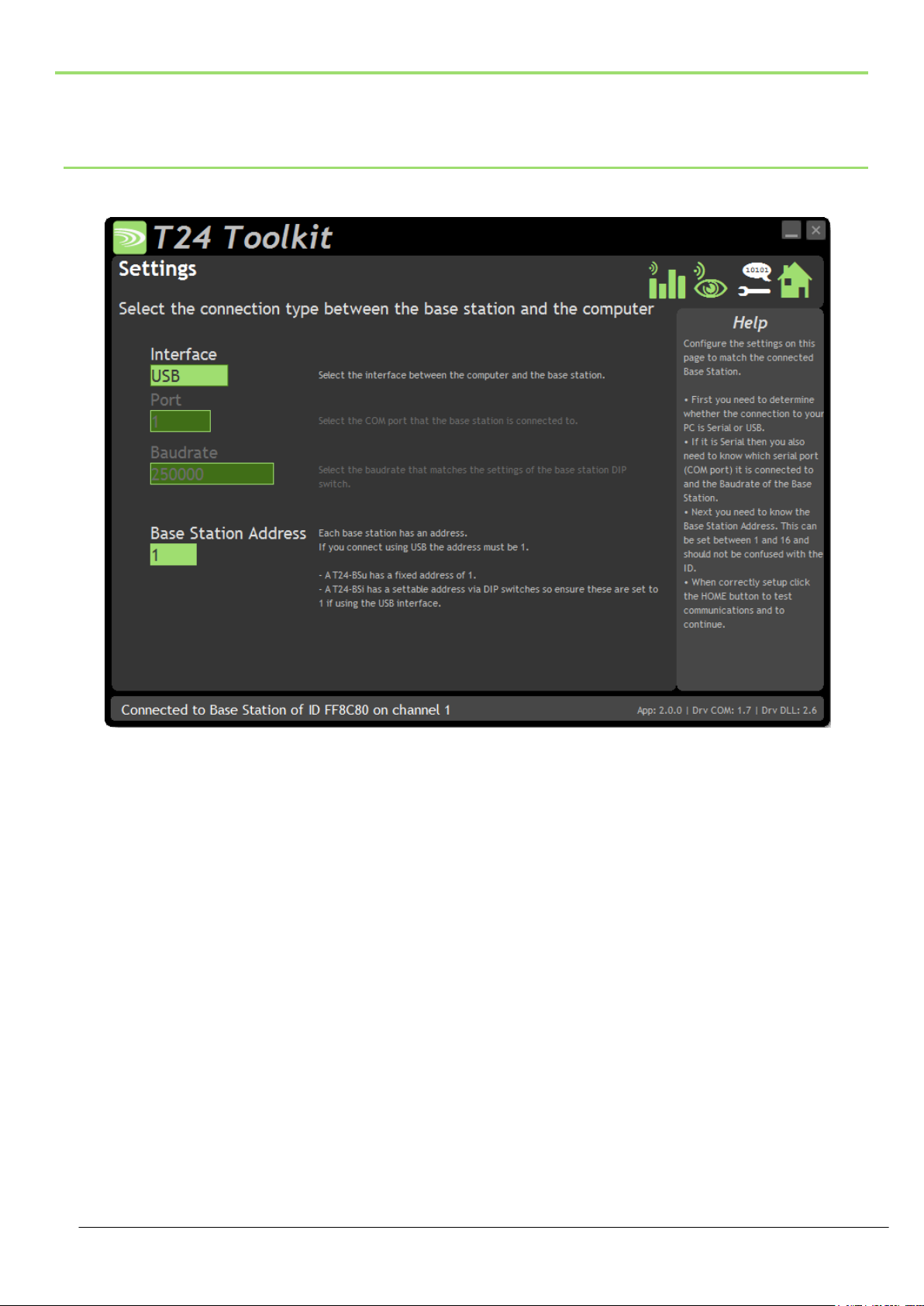
24
Common Toolkit Pages
These pages in the T24 Toolkit are applicable to all connected modules.
Setup Base Station Communications
Select the appropriate interface type for the connected base station. If the base station is connected via a serial
port then you will need to know the COM port it is connected to and the baud rate.
The Base Station Address is usually 1. This will only ever be different if it has been changed on base stations to
support multi base station configurations.
Click the Home button to attempt communications with the base station.
If no communications can be established the toolkit will remain on this page. You will need to check that the base
station is powered and that it is connected to any converters correctly.
Mantracourt Electronics Limited T24 Telemetry User Manual
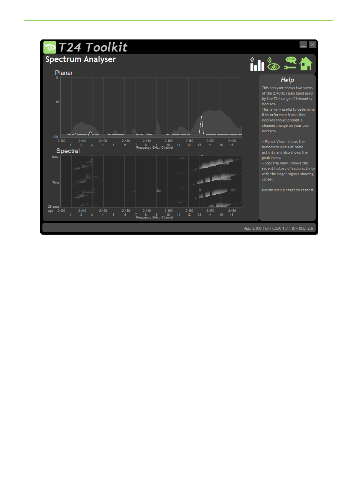
25
Analyser
The analyser page is provided as a tool and will not normally be needed unless you plan to change channels and
want to find the best channel to select, or to diagnose poor communications issues.
This page shows the radio signal levels detected across all the channels available to the T24 series of modules.
Using this tool may help in detecting noisy areas and allow you to decide on which channels you may want to
use.
The above charts show the traffic from a Wi-Fi network and it can be seen to be operating over channels 12 to 16
and it would be best (though not essential) to avoid using these channels.
Although 16 channels are shown the T24 modules operate over radio channels 1 to 15.
Mantracourt Electronics Limited T24 Telemetry User Manual
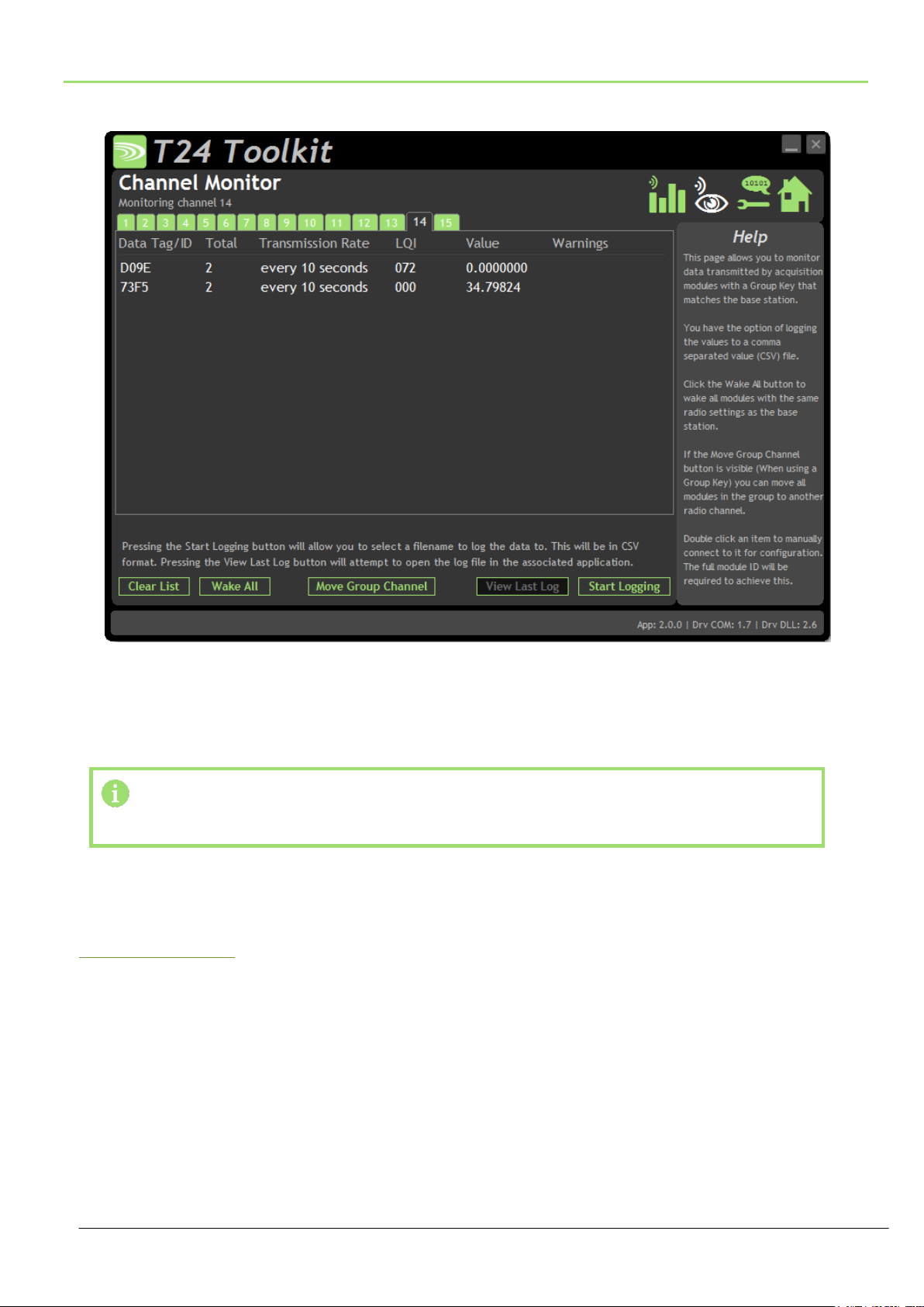
26
Channel Monitor
Items you can change or interact with:
Radio Channel Tabs
Click a tab to change the radio channel the base station is operating on
Clear List
Clear all detected messages from the list
Wake All
Wake all modules on the current radio channel
This page shows a summary of data sent by transmitter modules.
You can see the Data Tag of transmitted messages along with the total number of messages received, the
transmission rate, link quality, data value and any error messages.
Some base stations can also list modules that are sleeping. These will show an ID instead of a Data Tag.
To see any data the base station must be on the same radio channel as the transmitters
and must have a matching Group Key
The radio channel of the base station can be changed by clicking the channel tabs along the top of the page.
If you want to change the Group Key of the attached base station you need to configure its radio settings. See
Configure Base Station
Mantracourt Electronics Limited T24 Telemetry User Manual

27
Start Logging
Asks for a filename then logs the received data to a CSV file in the following
format:
Data Tag, Elasped ms, Value
View Last Log
Will launch the application associated with CSV files and open the last logged
file.
Move Group Channel
If the base station has a group key set then this button will be visible. Once at
least one module is present in the list this button will become enabled. Clicking
it will ask the user for a new radio channel then all detected transmitters, along
with all other modules on the same channel and group key such as handhelds,
will all be moved to the selected channel. Once this has been achieved the base
station itself will move and the list will start to fill again with messages on the
new radio channel.
You will only see a list of detected transmitters on this page
so you will need to ensure that any other receiver modules in
the group are available to be woken.
When this button is clicked all modules on the same radio
channel and group key will be woken before they are
changed to the target radio channel.
Mantracourt Electronics Limited T24 Telemetry User Manual
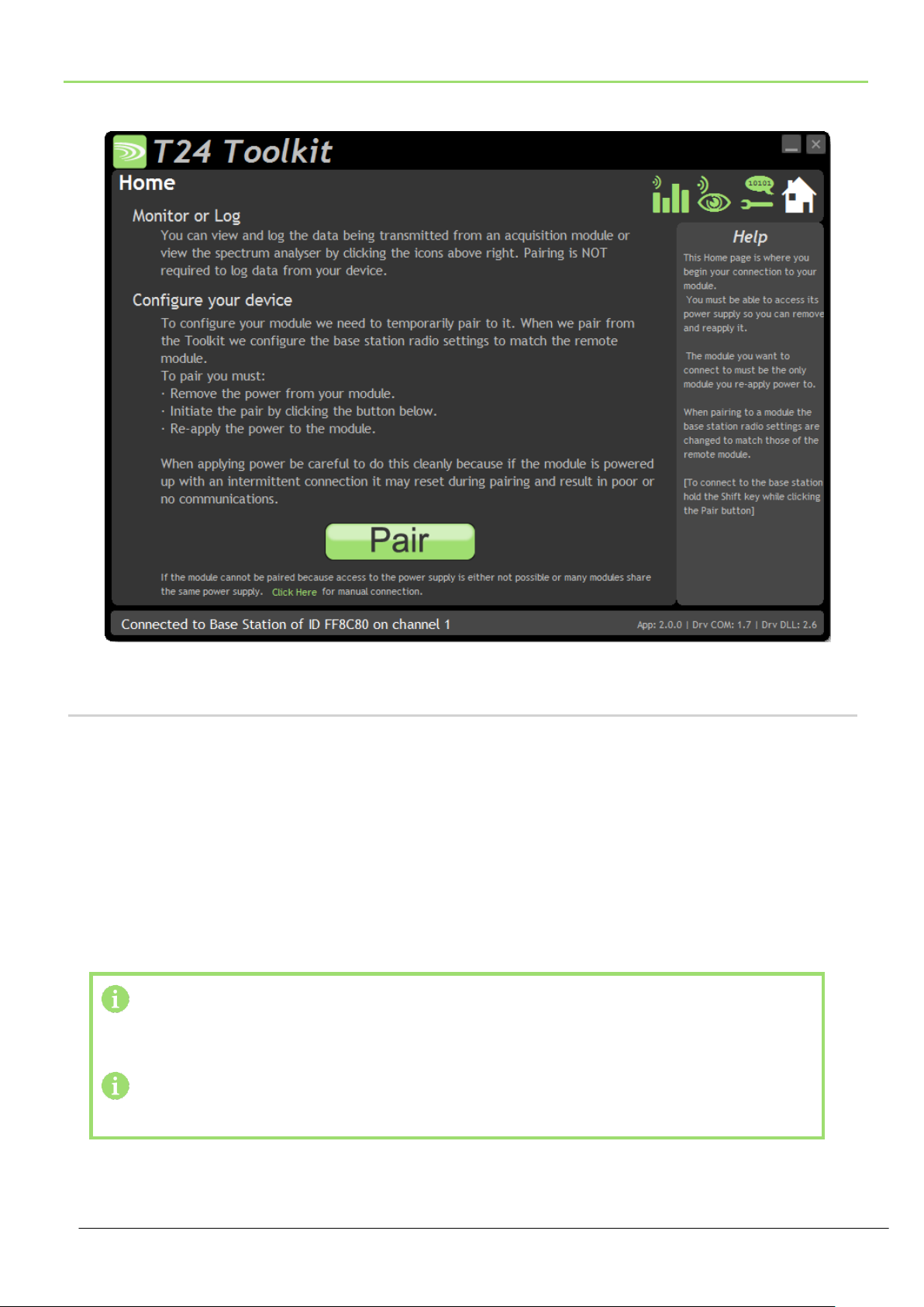
28
Home
You now have successful communications with the base station so you can now pair with our remote T24 module
or you can select the Spectrum Analyser mode or Data Provider Monitor mode.
Connecting to a remote module
To connect to a remote module you will pair. This is achieved by power cycling the module. Pairing removes the
need to know the radio settings of the module you are connecting to and also ensures that it is in a suitable state
for configuration.
Pairing Procedure
Remove power from the T24 module.
Click the Pair button on the Toolkit.
You now have 10 seconds to re-apply power to the T24 module.
If you connect successfully the Toolkit will change to the Information page. If the pairing fails try again.
Pairing with the toolkit will not change the radio configuration settings of the connected
module. The base station radio settings will be changed to match those of the remote
module.
When the toolkit connects to a remote module to enable configuration it will usually inhibit
the normal operational transmission of messages
Mantracourt Electronics Limited T24 Telemetry User Manual

29
Connecting to the attached base station module
To connect to and configure the connected base station, hold the shift key and click the Pair button.
Manual Connection
If you cannot get to the power supply of the remote module you can attempt to connect manually using Soft
Pairing. Click the ‘Click Here’ link at the bottom of the page and follow the prompts.
Mantracourt Electronics Limited T24 Telemetry User Manual
 Loading...