

Page 1
T24
-
ACMm & T24
-
BB1
Acquisition Connectivity Module
And Battery Box
User Manual
Page 2

Introduction / Overview ............................................................................................ 2
Getting Started ....................................................................................................... 2
Opening the Case ..................................................................................................... 2
Connecting Power..................................................................................................... 2
LED Indicator .......................................................................................................... 2
Connecting T24-BB1 toT24-ACMm .................................................................................. 3
Connecting Input Signals to T24-ACMm ............................................................................ 3
Using Completion Resistors ........................................................................................ 4
Half Bridge ............................................................................................................. 4
Quarter Bridge......................................................................................................... 5
Specifications ......................................................................................................... 5
General Radio ......................................................................................................... 5
T24-ACMi ............................................................................................................... 5
Approvals .............................................................................................................. 6
CE ....................................................................................................................... 6
FCC...................................................................................................................... 6
Industry Canada ....................................................................................................... 7
OEM / Reseller Marking and Documentation Requirements .................................................. 7
FCC...................................................................................................................... 7
IC ........................................................................................................................ 7
CE ....................................................................................................................... 7
Declaration of Conformity .......................................................................................... 9
Worldwide Regional Approvals .................................................................................... 10
Warranty............................................................................................................... 10
Page 3
2
Introduction / Overview
+
+
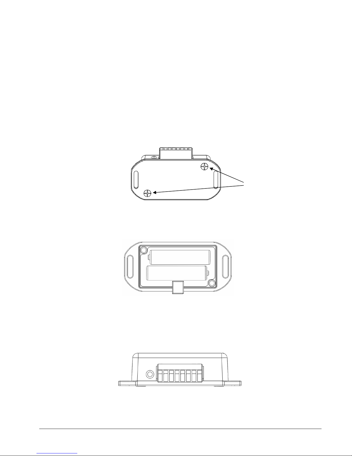
Remove these two screws
The T24-ACMm provides a convenient way to connect to one of the range of T24 acquisition modules. The T24ACMm also includes an LED for indicating when the device is transmitting.
The T24-BB1 provides 3V DC power to the T24-ACMm via a pair of ‘AAA’ cells.
Connecting an input to the acquisition module is also made easier by utilising 2 part screw terminals.
Getting Started
The T24-ACMm requires that the acquisition module is factory fitted therefore this requires specifying at the
time of ordering.
Opening the Case
The case lid is secured with 2 x Philips head screws, remove the screws and the case will come apart.
Connecting Power
Power is supplied by fitting 2 X ‘AAA’ cell 1.5 Volt batteries as directed inside the T24-BB1
Note there is no reverse polarity protection on the T24-BB1.
LED Indicator
The T24-ACMm is fitted with an LED to provide a visual indication of data transmission from the acquisition
module inside. The LED flashes when a data transmission occurs.
Mantracourt Electronics Limited T24-ACMm & T24-BB1 User Manual
Page 4
3
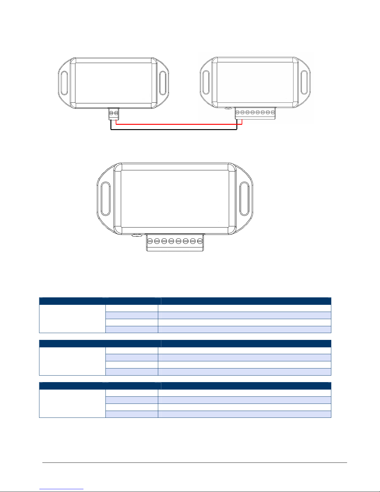
Connecting T24-BB1 toT24-ACMm
1 2 3 4 5 6 7 8
Connecting Input Signals to T24-ACMm
The connection of the input signals is dependent on what type of acquisition module is fitted. Please refer to
the table below. There may be additional input wiring requirements so please refer to the acquisition module
manual.
Acquisition Module Screw Terminal Function
5 -Excitation
T24-SAi, T24-SAFi
Acquisition Module Screw Terminal Function
T24-VAi
(0-10V)
Acquisition Module Screw Terminal Function
T24-IAi
(0-20mA 4-20mA
Calibrated)
Note Excitation Voltage 5V DC
6 -Signal
7 +Signal
8 +Excitation
5 -Excitation
6 -V in
7 +V in
8 + Excitation
5 -Excitation
6 -I in
7 +I in
8 +Excitation
Mantracourt Electronics Limited T24-ACMm & T24-BB1 User Manual
Page 5

4
R2
1 2 3 4 5 6 7 8
1 2 3 4 5 6 7 8
1 2 3 4 5 6 7 8
Using Completion Resistors
The T24-ACMm has the option for users to add up to three completion resistors, these can be used to enable
the T24-ACMm to accept half and quarter bridge strain input when a T24-SA (Strain Acquisition) module is
fitted. The three completion resistors are located as shown below:
If using a half bridge only R1 and R2 need to be fitted, we recommend low drift precision resistors to ensure
reading stability typically 0.1% 5ppm/oC. If using a quarter bridge R1,R2 and R3 must be fitted, R3 must be the
same resistance as the single gauge being used in the quarter bridge. The diagram below shows how you should
wire for full, half and quarter bridge configurations.
Full Bridge
Half Bridge
Mantracourt Electronics Limited T24-ACMm & T24-BB1 User Manual
Page 6

5
Quarter Bridge
1 2 3 4 5 6 7 8
1 2 3 4 5 6 7 8
High Reference
Low Reference
Specifications
General Radio
Min Typical Max Units
License License Exempt
Modulation method MS (QPSK)
Radio type Transceiver (2 way)
Data rate 250 K bits/sec
Radio Frequency 2.4000 2.4835 GHz
Power 1 mw
Range RAD24i (Integrated antenna) 100 (320) Metres (feet) *
Channels (DSSS) 16
* Maximum range achieved in open field site with T24-SA at a height of 3 metres above ground and T24-HS held
at chest height pointing towards the T24-SA.
T24-ACMm
Parameter Minimum Typical Maximum Units
Battery Supply Voltage 2.1 3 3.6 Volts dc
Operating Temperature Range* -40 - +65*
Storage Temperature Range -40 - +85
Environmental protection IP54
*Check operating temperature batteries intended for use.
The specifications for the actual fitted acquisition module are listed in the acquisition module manual.
°
C
°
C
Mantracourt Electronics Limited T24-ACMm & T24-BB1 User Manual
Page 7

6
Approvals
Suomalainen:
CE
Complies with EMC directive. 2004/108/EC
The Radio Equipment and Telecommunications Terminal Equipment (R&TTE) Directive,
1999/5/EC,
European Community, Switzerland, Norway, Iceland, and Liechtenstein
English: This equipment is in compliance with the essential requirements and other relevant provisions of
Directive 1999/5/EC.
Deutsch: Dieses Gerät entspricht den grundlegenden Anforderungen und den weiteren entsprecheneden
Vorgaben der Richtlinie 1999/5/EU.
Dansk: Dette udstyr er i overensstemmelse med de væsentlige krav og andre relevante bestemmelser i
Directiv 1999/5/EF.
Español: Este equipo cumple con los requisitos esenciales asi como con otras disposiciones de la Directive
1999/5/EC.
Français: Cet appareil est conforme aux exigencies essentialles et aux autres dispositions pertinantes de la
Directive 1999/5/EC.
Íslenska: Þessi búnaður samrýmist lögboðnum kröfum og öðrum ákvæðum tilskipunar 1999/5/ESB.
Italiano: Questo apparato é conforme ai requisiti essenziali ed agli altri principi sanciti dalla Direttiva
1999/5/EC.
Nederlands: Deze apparatuur voldoet aan de belangrijkste eisen en andere voorzieningen van richtlijn
1999/5/EC.
Norsk: Dette utstyret er i samsvar med de grunnleggende krav og andre relevante bestemmelser i EU-
directiv 1999/5/EC.
Português: Este equipamento satisfaz os requisitos essenciais e outras provisões da Directiva 1999/5/EC.
Tämä laite täyttää direktiivin 1999/5/EY oleelliset vaatimukset ja on siinä asetettujen muidenkin
ehtojen mukainen.
Svenska: Denna utrustning är i överensstämmelse med de väsentliga kraven och andra relevanta
bestämmelser i Direktiv 1999/5/EC.
This equipment is in compliance with the essential requirements and other relevant provisions of Directive
1999/5/EC.
FCC
Family: RAD24
Models: i and e for internal and external antenna variants. For antenna T24-ANTA and T24-ANTB
FCC ID:VHARAD24
This device complies with Part 15c of the FCC Rules. Operation is subject to the following two conditions: (1) this
device may not cause harmful interference, and (2) this device must accept any interference received, including
interference that may cause undesired operation.
CAUTION: If the device is changed or modified without permission from Mantracourt Electronics Ltd, the user
may void his or her authority to operate the equipment.
Mantracourt Electronics Limited T24-ACMm & T24-BB1 User Manual
Page 8

7
Industry Canada
Models: i and e for internal and external antenna variants. For antenna T24-ANTA and T24-ANTB
IC:7224A-RAD24
This apparatus complies with RSS-210 - Low-power Licence-exempt Radio communication Devices (All
Frequency Bands): Category I Equipment RSS.
OEM / Reseller Marking and Documentation Requirements
FCC
The Original Equipment Manufacturer (OEM) must ensure that FCC labelling requirements are met. This
includes a clearly visible label on the outside of the final product enclosure that displays the contents as
shown:
Contains FCC ID:VHARAD24
This device complies with Part 15 of the FCC Rules. Operation is subject to the following two conditions:
(1) this device may not cause harmful interference and
(2) this device must accept any interference received, including interference that may cause undesired operation.
The acquisition modules have been tested with T24-ANTA and T24-ANTB. When integrated in OEM products,
fixed antennas require installation preventing end-users from replacing them with non-approved antennas.
Antennas other than T24-ANTA and T24-ANTB must be tested to comply with FCC Section 15.203 (unique
antenna connectors) and Section 15.247 (emissions).
Acquisition modules have been certified by the FCC for use with other products without any further
certification (as per FCC section 2.1091). Changes or modifications not expressly approved by Mantracourt
could void the user’s authority to operate the equipment.
In order to fulfil the certification requirements, the OEM must comply with FCC regulations:
1. The system integrator must ensure that the text on the external label provided with this device is placed on
the outside of the final product.
2. The acquisition modules with external antennas may be used only with Approved Antennas that have been
tested by mantracourt.
IC
Labelling requirements for Industry Canada are similar to those of the FCC. A clearly visible label on the
outside of the final product enclosure must display the following text:
Contains Model RAD24 Radio (2.4 GHz), IC:7224A-RAD24
Integrator is responsible for its product to comply with RSS-210 - Low-power Licence-exempt Radio
communication Devices (All Frequency Bands): Category I Equipment RSS.
CE
The T24 series has been certified for several European countries.
If the acquisition module is incorporated into a product, the manufacturer must ensure compliance of the final
product to the European harmonized EMC and low-voltage/safety standards. A Declaration of Conformity must
be issued for each of these standards and kept on file as described in Annex II of the R&TTE Directive.
Furthermore, the manufacturer must maintain a copy of the T24 device user manual documentation and ensure
the final product does not exceed the specified power ratings, antenna specifications, and/or installation
requirements as specified in the user manual. If any of these specifications are exceeded in the final product, a
submission must be made to a notified body for compliance testing to all required standards.
OEM Labelling Requirements
The ‘CE’ marking must be affixed to a visible location on the OEM product.
Mantracourt Electronics Limited T24-ACMm & T24-BB1 User Manual
Page 9

8
The CE mark shall consist of the initials “CE” taking the following form:
If the CE marking is reduced or enlarged, the proportions given in the above graduated drawing must be
respected.
The CE marking must have a height of at least 5mm except where this is not possible on account of the
nature of the apparatus.
The CE marking must be affixed visibly, legibly, and indelibly.
Mantracourt Electronics Limited T24-ACMm & T24-BB1 User Manual
Page 10

9
Declaration of Conformity
We, Mantracourt Electronics Limited
The Drive
Farringdon
Exeter
Devon EX5 2JB
declare under our sole responsibility that our products in the T24 Radio Telemetry Product Range to which
this declaration relates are in conformity with the appropriate standard EN 300 328 following the provisions of
the Radio and Telecommunications Terminal Equipment Directive 1999/5/EC, FCC CFR Title 47 part 15c BS EN
61000-4-2 and BS EN 61000-4-3 following the provisions of the EMC Directive 2004/108/EC and Low Voltage
Directive 2006/95/EC.
December 2007
Brett James
Development Manager
Mantracourt Electronics Limited.
FCC ID:VHARAD24
Mantracourt Electronics Limited T24-ACMm & T24-BB1 User Manual
Page 11

10
Worldwide Regional Approvals
REGIS TERED FI RM
Region Product Conforms To
Europe CE
USA FCC
Canada IC
Australia To Be Determined
China To Be Determined
Japan To Be Determined
Important Note
Mantracourt does not list the entire set of standards that must be met for each country. Mantracourt customers
assume full responsibility for learning and meeting the required guidelines for each country in their distribution
market. For more information relating to European compliance of an OEM product incorporating the T24 range
of modules, contact Mantracourt, or refer to the following web site: www.ero.dk
Warranty
All Telemetry products from Mantracourt Electronics Ltd., ('Mantracourt') are warranted against defective
material and workmanship for a period of (1) one year from the date of dispatch.
If the 'Mantracourt' product you purchase appears to have a defect in material or workmanship or fails during
normal use within the period, please contact your Distributor, who will assist you in resolving the problem. If it
is necessary to return the product to 'Mantracourt' please include a note stating name, company, address,
phone number and a detailed description of the problem. Also, please indicate if it is a warranty repair.
The sender is responsible for shipping charges, freight insurance and proper packaging to prevent breakage in
transit.
'Mantracourt' warranty does not apply to defects resulting from action of the buyer such as mishandling,
improper interfacing, operation outside of design limits, improper repair or unauthorised modification.
No other warranties are expressed or implied. 'Mantracourt' specifically disclaims any implied warranties of
merchantability or fitness for a specific purpose. The remedies outlined above are the buyer’s only remedies.
'Mantracourt' will not be liable for direct, indirect, special, incidental or consequential damages whether based
on the contract, tort or other legal theory.
Any corrective maintenance required after the warranty period should be performed by 'Mantracourt' approved
personnel only.
ISO 900 1
In the interests of continued product development, Mantracourt Electronics Limited reserves the right to alter product specifications
without prior notice.
Code No. 517-924 Issue 1.0 04.05.11
Mantracourt Electronics Limited T24-ACMm & T24-BB1 User Manual
 Loading...