

Page 1
Instruction Sheet
Features
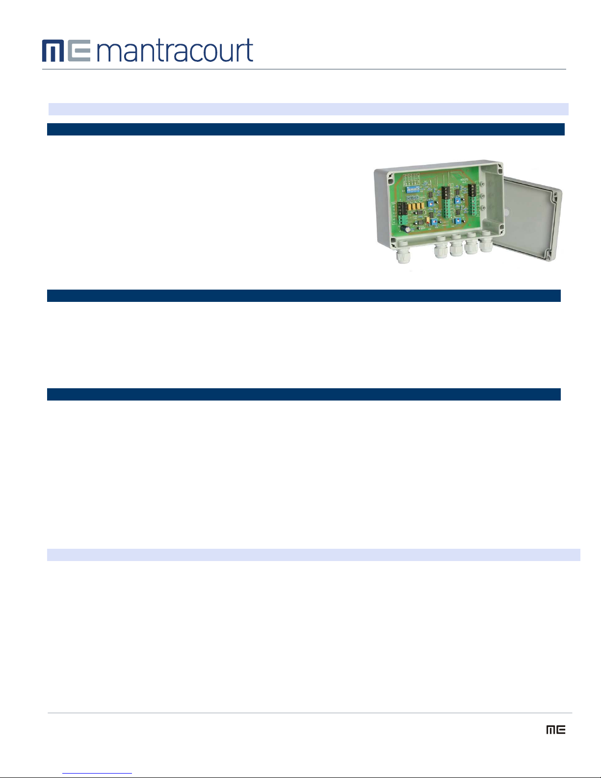
The Strain Gauge Junction Box is used to sum the outputs from up to
4 Strain Gauges to allow them to be connected to the LCA15/ADW15
Strain Gauge Indicator/Controller
The individual channel gains can be set up via DIL switches and
preset potentiometers to allow for 2, 3, or 4 Strain Gauges
Gain is not interactive and offset is preset, to speed up matching of
Strain Gauge gain
JBA
Load Cell Active Junction Box
Introduction
The load cell Junction Box is used to sum the outputs up to 4 load cells to allow them to be connected to an ADW15.
The individual channel gains can be set up via DIL switches and preset potentiometers to give an overall gain of unity when 1,
2, 3 or 4 load cells are connected (e.g. when 2 load cells are used each channel as a gain of 0.5)
The switch setting diagram inside the JBA assumes that the load cell channels are filled starting from No.1 through to No.4 as
required. Unused channels should be linked out (+IN to - IN).
Switch settings
Number of
Strain
Gauges
Connected
1
2
3
4
The unit is designed for 4 wire Strain Gauges, should 6 wire Strain Gauges be
used, their excitation and sense wires should be both connected to the
appropriate 'E' terminals.
The 4 channels can be matched by adjusting the 'Channel Gain' potentiometers
having first set the DIL switches for the number of Strain Gauges used.
If access to individual Strain Gauges is possible eg before the platform or hopper
is in position, then calibration can be carried out by placing a weight on one of
the cells, and noting the change in display reading on the ADW15.
SW1-1
ON
OFF
ON
OFF
SW1-2
ON
ON
OFF
OFF
SW1-3
OFF
OFF
ON
OFF
SW1-4
OFF
ON
OFF
OFF
SW1-5
OFF
OFF
ON
OFF
Repeat this for each remaining Strain Gauge, and adjust the ‘Channel Gain'
potentiometers, to give the same change in display reading for each cell used.
Should the platform already be in position it will be necessary to use a millivolt
source to carry out the calibration. Apply a voltage of 10 times the millivolt/volt
figure given for the appropriate Strain Gauge, to each channel in turn, adjusting
the 'Channel Gains' to give equal changes in display readings for each cell used.
SW1-6
OFF
OFF
OFF
OFF
SW1-7
OFF
OFF
OFF
OFF
SW1-8
OFF
OFF
OFF
OFF
Gain Range
(via preset)
x 1 – 0.5
x 0.33 – x 0.5
x 0.25 – 0.33
x 0.20 – 0.25
Specifications
Input
Channel Gain
Dimensions
Up to 20mV/V
x 1 to x 0.25 to allow for 1-4 load cells, DIL switch selectable with potentiometer for fine trim.
200 x 120 x 75mm ABS
JBA Instruction Sheet Issue 1.6 05.03.07 www.mantracourt.co.uk sales@mantracourt.co.uk tel +44 (0)1395 232020
Page 2

C
In the interests of continued product development, Mantracourt Electronics Limited reserves the right to alter product specifications without prior notice.
JBA Instruction Sheet Issue 1.6 05.03.07 www.mantracourt.co.uk sales@mantracourt.co.uk tel +44 (0)1395 232020
 Loading...