

Page 1
USER MANUAL
(May 2017)
FSU-SSBD
Fast USB Strain Gauge/Load Cell Digitiser Module
APPROVED DISTRIBUTORS OF:
Page 2

Mantracourt Electronics Limited – FSU User Manual
1
Contents
Chapter 1 Introduction ........................................................................................................................................................2
Overview ........................................................................................................................................................................... 2
LED Status Indication ...................................................................................................................................................... 2
Chapter 2 Getting Started ...................................................................................................................................................3
Communications Interface Information ...................................................................................................................... 3
FSU Toolkit ....................................................................................................................................................................... 3
What Can The Toolkit Do? ........................................................................................................................................................................... 3
Installing FSU Toolkit ...................................................................................................................................................................................... 3
Connecting the Module to the Computer ................................................................................................................... 5
Using the Found New Hardware Wizard ................................................................................................................................................ 5
Using the Software .......................................................................................................................................................................................... 6
Home Page .................................................................................................................................................................................................... 7
Information Page ......................................................................................................................................................................................... 8
Save and Restore Page ........................................................................................................................................................................... 10
Lock Page ..................................................................................................................................................................................................... 11
Calibration Page ........................................................................................................................................................................................ 12
System Zero ........................................................................................................................................................................................ 13
Auto Calibration ..................................................................................................................................................................................... 13
Table Calibration ............................................................................................................................................................................... 14
Engineering Units .............................................................................................................................................................................. 14
Capture Page .............................................................................................................................................................................................. 15
Review Page ................................................................................................................................................................................................ 17
Scope Page .................................................................................................................................................................................................. 20
FFT Page ............................................................................................................................................................................. 21
Chapter 3 Installation ....................................................................................................................................................... 23
Identifying Strain Gauge Connections ....................................................................................................................... 23
9 way D Connector Pin-outs ..................................................................................................................................................................... 23
4-wire load cell ............................................................................................................................................................................................... 23
6-wire load cell ............................................................................................................................................................................................... 23
Chapter 4 Specifications .................................................................................................................................................. 24
Technical Specifications ............................................................................................................................................... 24
Dimensions & Mounting .............................................................................................................................................. 25
External Dimensions ................................................................................................................................................................................. 25
LED Position ................................................................................................................................................................................................ 25
Mounting Holes ......................................................................................................................................................................................... 25
DIN Rail Mounting (Optional Kit)........................................................................................................................................................ 26
Cable Clearance ......................................................................................................................................................................................... 26
Cable Retention ......................................................................................................................................................................................... 27
Environmental Approvals ................................................................................................................................................ 27
CE Approvals .................................................................................................................................................................................................... 27
Warranty ............................................................................................................................................................................. 27
Page 3

Mantracourt Electronics Limited – FSU User Manual
2
Chapter 1 Introduction
This chapter provides an introduction to the FSU products, describing the product range and main features.
Overview
The FSU product family comprises of Digital Sensor Cards that connect strain bridge sensors to your PC via USB.
The FSU product is a compact, high-precision Strain Gauge Converter; converting a strain gauge sensor input to a
digital output and is connected to a PC via a USB port. They allow high precision measurements to be made and
communicated directly to a PC and is aimed at applications which require high-speed measurement.
Simply by plugging the device into a PC, data can be extracted from most strain gauge bridge input sensors and
acquired by software which allows data manipulation removing the need for amplifiers, filters & multimeters.
Free-standing module fitted with 9-way ‘D’ type socket for load cell.
Micro USB socket accepts a USB lead with type ’A’ connector at the PC end.
LED Status Indication
The module indicates status via a red Healthy LED.
When the FSU is placed in configuration mode the LED will be on solidly.
When the FSU is in recording mode and transmitting data the LED should flash ON for 100ms every 500ms (LED will
be OFF but flash on for a tenth of a second every half a second).
If the integrity of the load cell is in doubt the LED will flash OFF for 100ms every 500ms (LED will be ON but flash off
for a tenth of a second every half a second).
Page 4

Mantracourt Electronics Limited – FSU User Manual
3
Chapter 2 Getting Started
Install software (But do not run it)
Plug FSU module into USB port
Run software
This chapter explains how to connect to a FSU for the first time and how to get it working.
Communications Interface Information
FSU modules can connect to a PC by plugging into a USB port and do not require an external power supply as they
appear as a ‘single unit load’ i.e. they draw <100mA.
Appropriate USB drivers must be installed which are automatically installed with the FSU Toolkit software.
FSU Toolkit
The FSU Toolkit is a configuration and analytical tool designed specifically for configuring FSU modules.
This toolkit allows configuration, calibration, data recording and review and for parameter management of the
modules.
What Can The Toolkit Do?
Communications with a single module at a time to do the following:
Viewing of input with indication of integrity errors.
Two point auto calibration by application of known weight.
Two point table calibration from load cell calibration certificate.
Setting System Zero.
Engineering unit selection.
Save module settings including user calibration and ability to restore to same or different USB FSU modules.
Capture up to 30 minutes of data at 4800 Hz. Save data to CSV file. Navigate up to 30 minutes of data
captured from the FSU or loaded from a previously saved CSV file.
Trend chart view of live input. Exportable image and data.
FFT view to identify frequency components of input signal.
Simple oscilloscope view for wave based signals between 1 Hz and 500 Hz.
Easily switch to alternative engineering units (If module has been previously calibrated)
It should be noted that traditional logging (Where the user start and stops a log) is not required with the FSU Toolkit.
The FSU module operates in two modes. The first mode is where the measured value is being constantly transmitted
at 4800 Hz and the other mode is configuration mode where the Toolkit can talk to the module but the measured
value is not being constantly streamed. As will be seen later, the Toolkit allows capturing up to the last 30 minutes of
data as long as the user stays out of the configuration pages. This 30 minute block of data is easily and quickly
navigated to isolate data of interest.
Installing FSU Toolkit
Install the FSU Toolkit software by inserting the CD or USB storage device. This should start the ‘AutoRun’ process,
unless this is disabled on your computer.
(If the install program does not start of its own accord, run FSU Toolkit Setup.exe from the installation media.
Alternatively launch the installer executable file which may have been downloaded from a web site.
The installation software pre-installs the required USB drivers so that they can be automatically found when the
hardware is plugged in later on.
Page 5

Mantracourt Electronics Limited – FSU User Manual
4
After the software has been installed please connect the module to the PC and see the next
section before running the FSU Toolkit
Page 6
Mantracourt Electronics Limited – FSU User Manual
5
Connecting the Module to the Computer
Connect to a USB port on the Windows PC using the cable provided with the module.
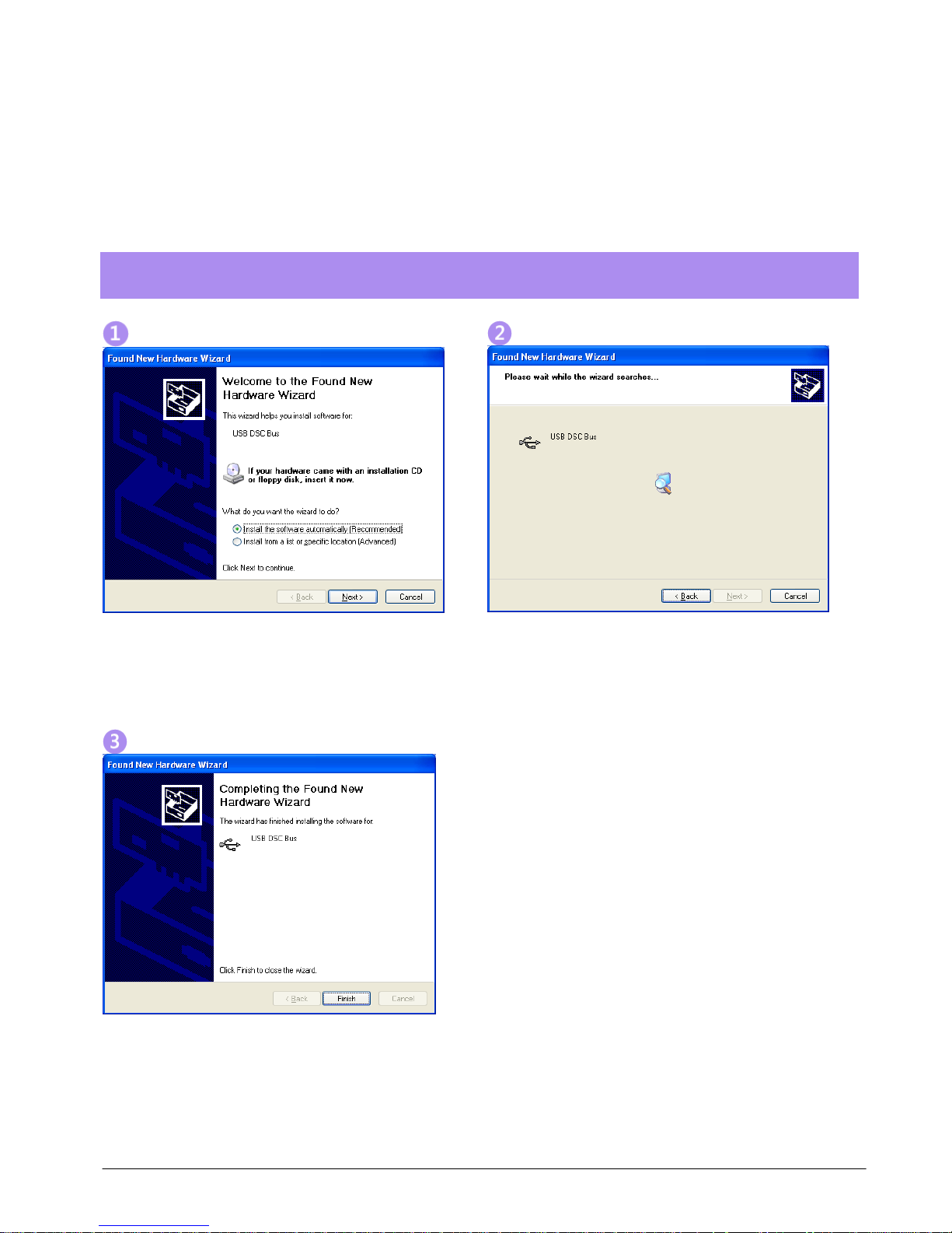
Using the Found New Hardware Wizard
Connecting the module will cause the following dialog windows to appear. NOTE: Different operating systems may
present different dialog windows but the dialogs shown below should allow you make the correct choices regardless
of operating system.
Note that the FSU shares the drivers with the DSC range of modules so the driver is described as
the USB DSC Bus.
The ‘Found New Hardware Wizard’ should now appear.
Select ‘No, not at this time’ if you are asked whether
the drivers should be searched for online.
Click ‘Next’.
Now the wizard will start searching for the drivers.
The wizard should then proceed with installing the
software drivers.
Page 7

Mantracourt Electronics Limited – FSU User Manual
6
Using the Software
You can now launch the FSU Toolkit software.
Only one FSU module at a time can be connected to a PC!
The FSU Toolkit automatically detects the connected FSU module.
If the FSU module is detected when you launch the FSU Toolkit it will be automatically selected and the
Information page will be displayed.
If the module is not detected you will see the Home page at which you can wait until the FSU module is connected.
Pressing the Detect button will start the detection process.
The Review page is also available at this point. See later in the manual for using the Review page. This will allow you
to review previously saved data.
Recording occurs continuously in the background while on any of the following pages:
Capture, Review, Scope, FFT
and will continue even while navigating between these pages.
However, switching to any of the other pages
Home, Information, Save & Restore, Lock, Calibration
will cause the recording to stop.
Page 8

Mantracourt Electronics Limited – FSU User Manual
7
Home Page
Click the icon to access the Information page.
After clicking the ‘Detect’ button and a module is detected you will then see the Information page.
Page 9
Mantracourt Electronics Limited – FSU User Manual
8
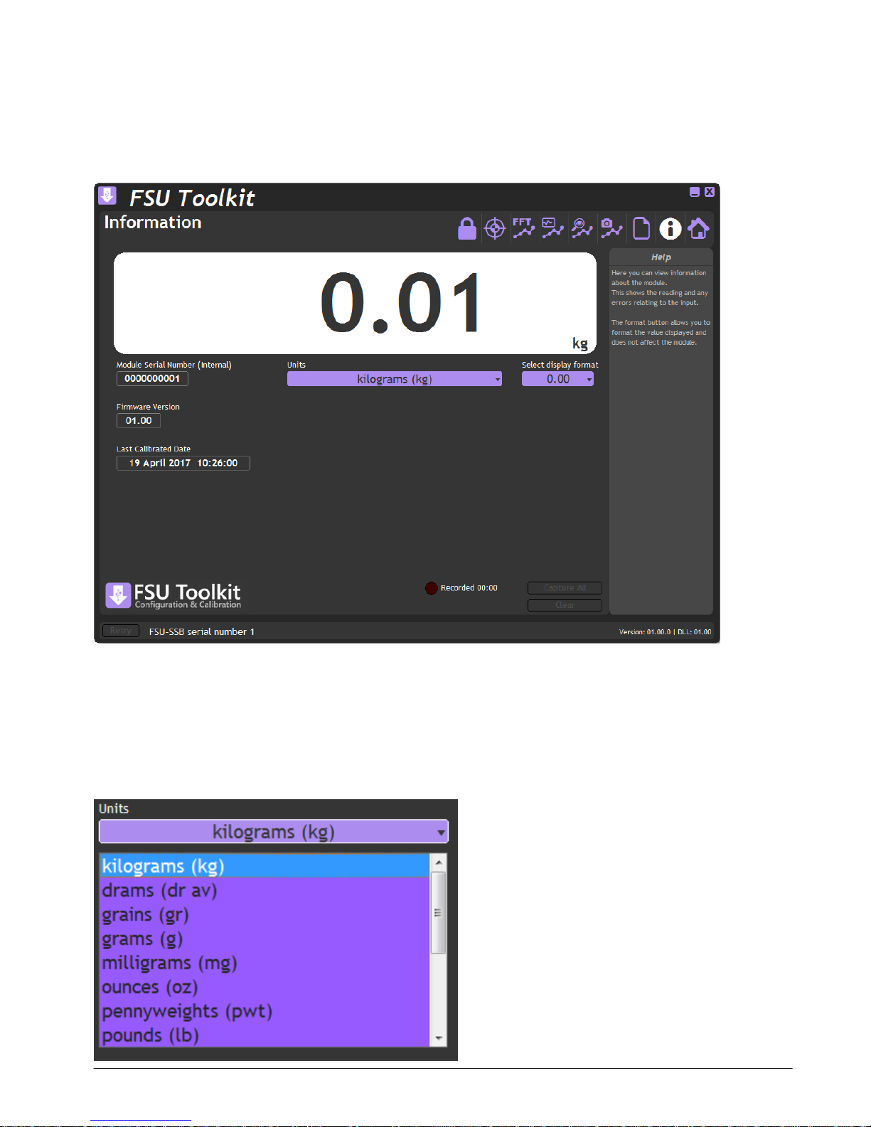
Information Page
Click the icon to access the Information page.
No data is recorded while on this page.
This simply shows a large display and indicates if any error conditions are present by displaying an information box.
The module serial number, firmware version and last calibration date are also shown.
If the module has been allocated engineering units these will be displayed in the lower right of the LCD display.
Units
If the calibrated units have been defined for this module then you can select from a list of alternative engineering
units to use.
Page 10

Mantracourt Electronics Limited – FSU User Manual
9
This feature may be locked on certain modules.
Format
Clicking the ‘Format’ button allows you to select a new format for the displayed value. By using this you can hide
unwanted decimal places.
Just click the required display format in the list.
Error Indication
If any errors are detected these will be shown under the main display. The following screenshot shows an Integrity
error present.
The error box will disappear once the error is no longer present.
Page 11

Mantracourt Electronics Limited – FSU User Manual
10
Save and Restore Page
Click on the icon to open the Save & Restore page.
No data is recorded while on this page.
Clicking the ‘Save’ buttons will allow you to specify a file to which the configuration of the connected module is
written.
Once saved this file can be selected, after clicking the ‘Restore’ button, and the settings restored to the same
module or to another module.
Page 12

Mantracourt Electronics Limited – FSU User Manual
11
Lock Page
Click on the icon to open the Lock page.
No data is recorded while on this page.
This page will allow the locking of certain functions. Once any item has been changed from Show to Hide or Allow to
Lock then subsequent attempts to open this page (And thus show the hidden functions again) will result in the user
being asked for a Passcode.
The Passcode entered must match the one entered on this page to grant access.
It is important to remember the Passcode before leaving this page after any of the options have
been set to Hide. You will need to contact Mantracourt to aid in Passcode recovery should the
Passcode be forgotten!
Calibration Page – Allows you to either Allow or Lock access to the calibration page.
System Zero Function – Locking this function will also force locking of the Calibration Page. This is useful if the
Calibration Page has been locked but you want to still offer the ability to set the System Zero. Just set this to Allow
after setting the Calibration Page to lock.
Display Units Change - Hiding this function will also force locking of the Calibration Page. This is useful if you want
to lock access to the Calibration Page but allow the user to change the displayed engineering units. Just set this to
Show after setting the Calibration Page to lock.
Page 13

Mantracourt Electronics Limited – FSU User Manual
12
Calibration Page
Click on the icon to open the Calibration page.
This page allows you to calibrate the module using various methods, perform system zero and set calibrated
engineering units.
mV/V Input – Shows the actual mV/V input as measured by the module.
Calibrated Value – Shows the calibrated value.
Defaults – Clicking the Defaults button will remove any user level calibration and return the module to its factory
calibrated state.
The page is separated by tabbed sections; Automatic Calibration, Table Calibration and Engineering Units. Click a tab
to change sections.
Page 14

Mantracourt Electronics Limited – FSU User Manual
13
System Zero
System Zero is used to remove permanent values from an installed system such as the weight of a vessel or weighing
platform to give a zero Gross value.
The value shown on this page is subtracted from the measured value.
You can either type a value in manually or click the Zero Now button to automatically fill in the value to give a zero
reading based on the current input.
This feature can be hidden on the Lock Page.
Auto Calibration
The automatic calibration requires that you apply two known (ascending) inputs in sequence. Just enter the required
engineering unit value for the two inputs in the fields marked 1 and 2.
Next, apply the low input and allow a settle time. Click the ‘Acquire’ button then apply the higher input. After
another settle time click the second ‘Acquire’ button and the calibration is complete.
Page 15

Mantracourt Electronics Limited – FSU User Manual
14
Table Calibration
This option lets you calibrate direct from the load cell manufacturers certificate without having to apply weights to
the input.
Choose 2 points from the load cell certificate and enter the mV/V values and the weights on the certificate (or
convert the certificate weight to any other engineering unit of your choice) click the ‘Calibrate’ button and the
calibration is complete.
Engineering Units
This allows you to specify the engineering units that the module was calibrated in. Changing this does not affect the
calibration. It simply assigns the engineering units to the calibrated value so that later the user can select different
engineering units and the module output value will be automatically converted to the selected units.
If you do not want the user changing the units you can hide access to that feature on the Lock Page.
If you do not want to display any engineering units then select Undefined from the list and no units will be displayed
next to the value on the Information Page and the user will not be able to select or change the displayed
engineering units.
Page 16

Mantracourt Electronics Limited – FSU User Manual
15
Capture Page
Click on the icon to open the Capture page.
This page helps you to see what is happening in real-time to the input of the module. All the other pages offer you
the options of Capture All to capture and review everything recorded so far. This page allows you to capture shorter
durations and to see the state of the input for those times when you can identify when to capture the input data.
View Window
Select the viewing window into the real-time data by selecting between 1 and 30 seconds using the slider. The input
data is displayed on the chart.
Transient Enhance
Selecting this option will enhance the display to better identify fast transient peaks. Because of the way a large
amount of data is subsampled to enable it to fit on the chart, fast peaks may not appear or may flash in and out of
visibility as the data flows past the chart. This feature will have the side effect of creating a slightly fuzzy edge on
slower moving data. This does not affect the way data is recorded, only the way it is shown on the chart. When used
in conjunction with the Show Min Max feature this can help stabilize the view of data.
Show Min Max
By default the chart auto scales as the data moves across it which means that if a transient occurs the chart will
rescale but once that transient leaves the viewport the chart will autoscale again based on the lower magnitude data
that follows. By selecting this feature the chart scaling will be locked to the minimum and maximum values detected
while the feature is active.
Also, when activated, the values of the detected min and max along with the difference between the two are
displayed in the lower right of the window in the Help pane.
Page 17

Mantracourt Electronics Limited – FSU User Manual
16
To deactivate the Min Max function set the switch to off. Next time it is switched on the min and max values will be
reset.
Capture Viewed
Although you are always able to Capture All data recorded so far, this Capture Viewed button gives you the options
of capturing only the data currently visible on the chart. Sometimes the data you are interested in can be recognised
from the chart so this avoids having to capture and review all of the recorded data which may be up to 30 minutes
worth.
Copy Chart Image
This feature is available by right-clicking on the chart and copies the chart image to the clipboard enabling pasting
into other applications.
Page 18

Mantracourt Electronics Limited – FSU User Manual
17
Review Page
Click on the icon to open the Review page.
This page can be selected by clicking the icon or it can be shown automatically by clicking the Capture All
button or the Capture Viewed button (Only available on the Capture Page).
This is where you can navigate through all the captured data, optionally discard unwanted data, view cursors and
load and save data).
The chart automatically enhances transient peaks so that there is no chance of missing important features in the
data. Once you have zoomed in enough so you can identify individual data points the enhancement is turned off
automatically.
Page 19

Mantracourt Electronics Limited – FSU User Manual
18
Navigation
The data navigation bar sits under the chart. The entire set of captured data is represented in the background
coloured purple. The lighter highlighted part shows the selected portion that is currently being displayed in the
chart. Thus the navigation control allows you to zoom in and out of the data as well as pan along through the data at
the current zoom level.
You can change the viewed data by dragging the highlighted portion as follows:
Expand or contract the highlight by clicking and dragging the cursor at the left-hand side of the highlight or
anywhere to the left of the highlight.
Expand or contract the highlight by clicking and dragging the cursor at the right-hand side of the highlight or
anywhere to the right of the highlight.
Or you can pan the highlight left and right by clicking and dragging in the middle of it.
Cursors
Left clicking on the chart will display the first cursor. The cursor snaps to the nearest data point and displays the data
and time and value of the data point in a box in the lower left of the chart.
The date is followed by the time in HH:MM:SS:mic ro seconds format then the value.
Cursors are turned off once the navigation control is used.
Page 20

Mantracourt Electronics Limited – FSU User Manual
19
Second Cursor
Turning this feature on will display a second cursor that can be positioned on the chart.
There is also some extra information displayed in the lower right of the window in the Help panel.
This displays the time difference between the two cursors (Plus the frequency if you had placed the cursors on two
adjacent features in a wave based signal) and the value difference.
Cursors are cleared once the navigation control is used.
Crop
When displaying large amounts of data (30 minutes of data equates to over 8.6 million data points) it is often only a
small portion that contains the actual data of interest. The crop button discards data that falls outside of the
currently viewed portion of the entire data set and resets the chart and navigation control to focus only on this data.
The newly focussed data can then be navigated, saved or again zoomed and cropped.
If a mistake is made during cropping, the entire data can be captured again.
Save
Save the entire data set to a CSV file. The file can be loaded again to be reviewed or loaded into a 3rd party program
for analysis. See CSV File Format later.
Load
Load a previously saved CSV data file back into the Toolkit for navigation and analysis.
Copy Chart Image
Page 21

Mantracourt Electronics Limited – FSU User Manual
20
This feature is available by right-clicking on the chart and copies the chart image to the clipboard enabling pasting
into other applications.
Scope Page
Click on the icon to open the Scope page.
This page offers a simple oscilloscope view of wave based input signal to help visualise what is happening.
From this page you have the ability to Clear the current recording or click Capture All to capture the entire recording
and display it in the Review page.
This page best allows viewing of frequencies of between 1 Hz and 500 Hz. You can view waveforms up to around 2
kHz but there will not be enough samples in the captured data to represent the proper waveform.
Auto Locate
Click this button to automatically select the best settings to view the current input waveform.
Trigger level
This selects the trigger level which is the value at which the left-hand side of the scope starts to draw the waveform.
Trigger
Turns the trigger on or off.
Edge Falling
Normally the trigger is set to detect a rising edge. Turn Edge Falling to On to detect the falling edge of the
waveform.
Copy Scope Image
This feature is available by right-clicking on the chart and copies the chart image to the clipboard enabling pasting
into other applications.
Page 22

Mantracourt Electronics Limited – FSU User Manual
21
FFT Page
Click on the icon to open the FFT page.
This page shows the relative magnitude of the frequency components of the input signal from 1 Hz to 2040 Hz.
A grey annotation will be displayed under the largest magnitude frequency detected. The above screenshot shows
50Hz detected.
Navigation
You can drag the thumbs at each end of the purple navigation bar to zoom into the frequency range of interest.
The purple bar can be panned as well as resized.
Peak Hold
When activated this simply holds the maximum for each frequency displayed until the feature is turned off.
Cursor
Click the chart to display the cursor. This can be dragged around the chart and displays the frequency of the point
under the cursor.
Page 23

Mantracourt Electronics Limited – FSU User Manual
22
Copy Chart Image
This feature is available by right-clicking on the chart and copies the chart image to the clipboard enabling pasting
into other applications.
Page 24

Mantracourt Electronics Limited – FSU User Manual
23
Chapter 3 Installation
This chapter gives detailed information on integrating the FSU into a production system – including mounting,
protection, adjustments, wiring and electrical requirements.
Identifying Strain Gauge Connections
9 way D Connector Pin-outs
4-wire load cell
6-wire load cell
Page 25

Mantracourt Electronics Limited – FSU User Manual
24
Chapter 4 Specifications
Technical Specifications
Parameter
Min
Typical
Max
Units
Strain Gauge Measurement
4 Wire
Strain Gauge Excitation Voltage
4. 5
5
5.25
VDC
Strain Gauge Drive Capability
80
-
5000
Ohms
Strain Gauge Sensitivity
-3
2.5 3 mV/V
Offset Temperature Stability
1 4
ppm/°C
Gain Temperature Stability
3 5
ppm/°C
Offset Stability with Time
20
90
ppm of FR (1)
Gain Stability with Time
30
ppm of FR (2)
Non Linearity before Linearization
5
25
ppm of FR
Internal Resolution
16 Million
Counts/divs
Resolution @ 4.8kHz readings (Noise stable) over 1s
8192
Counts/divs
Resolution @ 4.8kHz readings (Noise stable) over 1s
13 Bits
Measurement Sample Rate
4800
Per Second
Measurement Sample Rate Accuracy
±0.5
±1.1
%
Electrical
Min
Typical
Max
Units
Power Supply voltage
4.25
5
5.5
V dc
Power Supply current (350 Ohm Bridge)
68
75
mA
Data transmission
Min
Typical
Max
Units
Output cable length
5
m
Environmental
Min
Typical
Max
Units
Operating temperature range
-40
+85
°C
Storage temperature
-40
+85
°C
Humidity 0
95
%RH
Protection
IP50
Dimensions
Cased version
70.5 x 51 x 20mm excluding 9-way ‘D’ type socket
connector.
74.5 x 51 x 20mm including connector.
Notes.
1. From original offset at any time
2. 1st Year
Page 26

Mantracourt Electronics Limited – FSU User Manual
25
Dimensions & Mounting
The following diagrams show the case dimensions and mounting holes and optional DIN rail mounting kit.
External Dimensions
LED Position
Mounting Holes
Page 27

Mantracourt Electronics Limited – FSU User Manual
26
DIN Rail Mounting (Optional Kit)
A DIN rail mounting kit is available for top hat DIN rail EN 50022. Optional part DSCUSB-DIN consists of a pair of
screws and two DIN rail clips.
Remove the two screws on the rear of the FSU case and replace with the longer screws from the DSCUSB-DIN kit.
These longer screws secure the din rail clips which sit in the rectangular depressions around the screw holes.
NOTE: You may want to remove and replace one screw at a time to avoid the case coming apart.
Once fitted the top face of the FSU will be 31.4mm from the surface that the DIN rail is mounted on.
Cable Clearance
These are typical clearances but smaller mouldings or using a tighter cable radius can reduce this.
Page 28

Mantracourt Electronics Limited – FSU User Manual
27
Cable Retention
The 9 way ‘D’ socket can accept a mating plug that has screw retention functionality.
The micro USB socket does not have any form of cable retention and this must be taken into account if mounting
the FSU to ensure that the cable cannot disengage accidentally or through vibration.
Environmental Approvals
CE Approvals
European EMC Directive
2004/108/EC
BS EN 61326-1:2006
BS EN 61326-2-3:2006
Output shall not exceed the sum of uncertainties when subjected to an electric field of 10V/m over the frequency
range 80 to 600MHz
Warranty
All FSU products from Mantracourt Electronics Ltd., ('Mantracourt') are warranted against defective material and workmanship for a period of (3)
three years from the date of dispatch.
If the 'Mantracourt' product you purchase appears to have a defect in material or workmanship or fails during normal use within the period,
please contact your Distributor, who will assist you in resolving the problem. If it is necessary to return the product to 'Mantracourt' please include
a note stating name, company, address, phone number and a detailed description of the problem. Also, please indicate if it is a warranty repair.
The sender is responsible for shipping charges, freight insurance and proper packaging to prevent breakage in transit.
'Mantracourt' warranty does not apply to defects resulting from action of the buyer such as mishandling, improper interfacing, operation outside
of design limits, improper repair or unauthorised modification.
No other warranties are expressed or implied. 'Mantracourt' specifically disclaims any implied warranties of merchantability or fitness for a specific
purpose. The remedies outlined above are the buyer’s only remedies. 'Mantracourt' will not be liable for direct, indirect, special, incidental or
consequential damages whether based on the contract, tort or other legal theory.
Any corrective maintenance required after the warranty period should be performed by 'Mantracourt' approved personnel only.
Document Title:
FSU User Manual
Applies To:
FSU Product Range
Part Number:
517-941
Issue Number:
01.00
Dated:
23rd May 2017
In the interests of continued product development, Mantracourt Electronics Limited
reserves the right to alter product specifications without prior notice.
www.mantracourt.com
 Loading...