

Page 1

F6 SMART™
Echo
Volumetric Handheld Camera
User Guide
Revision: 0.1
For Echo™ Software Version: 1.2.0
Printed on: April 16, 2018
Confidential
Page 2
Legal Notice
Usage of this document, and all information (including product information) provided within, are subject to the following terms and
conditions, and all applicable laws.
This document contains highly confidential information, which is proprietary to Mantis Vision Ltd. Ltd. (MANTISVISION®) and/or its
affiliates (hereafter, "Mantis Vision Ltd."). No part of this document's contents may be used, copied in any form, disclosed or conveyed
rd
to any 3
document is intended for customers’ information and for negotiation purposes only. MANTISVISION® makes no implicit representations
or warranties with respect to such information. The information included in this document is subject to change without prior notice.
Any decision to rely on the information contained herein shall be at the reader’s sole discretion and accountability, and Mantis Vision
Ltd. will not accept any liability for such decision or for any damages resulting therefrom. Certain laws do not allow limitations on
implied warranties or the exclusion or limitation of certain damages. If such laws apply to the reader of this document, some or all the
above disclaimers, exclusions, or limitations may not be applicable.
All registered or unregistered trademarks, including but not limited to: MANTISVISION®, MV4D®, Echo™, F6 SMART™ as well as product
names, logos and other service marks mentioned within this document are the property of Mantis Vision Ltd.. Other trademarks
included in this document (and so marked) belong to their respective owners and are used for explanations only. Nothing contained
herein shall be construed as conferring by implication, estoppels, or otherwise any license or right, either express or implied, under any
patent or trademark of Mantis Vision Ltd. or any third party. Any use of Mantis Vision Ltd.-owned trademark may not be made without
the prior written authorization of Mantis Vision Ltd.. This document and all its contents are protected intellectual property of Mantis
Vision Ltd.. Any copying, reprinting, reuse, reproduction, adaptation, distribution or translation without the prior written permission of
Mantis Vision Ltd. is prohibited.
Please check your End User License Agreement (EULA) for terms and Conditions.
© Copyright Mantis Vision Ltd. Ltd. All rights reserved.
party in any manner whatsoever without prior written permission from Mantis Vision Ltd. The information included in this
Contacts
Mantis Vision Ltd. www.Mantis-Vision.com
24 Imber St., Kiryat Arie, Petach Tikva 49511, Israel Tel.: +972-3-5611660
Marketing: marketing@Mantis-Vision.com Tel.: 1-800-MANTISM
Support: support_team@Mantis-Vision.com Tel.: 1-800-MANTISS
Page 3

Table of Contents
F6 SMART™ Echo – Volumetric Handheld Camera – User Guide
3
Table of Contents
Chapter 1 Foreword .........................................................................................................9
About Mantis Vision Ltd. ............................................................................................... 9
About the F6 SMART™ System ...................................................................................... 9
Intended Audience ....................................................................................................... 11
Document Overview .................................................................................................... 11
Conventions used in this Document ........................................................................... 12
Chapter 2 Laser Safety Precautions ...............................................................................13
General .......................................................................................................................... 13
Engineering ................................................................................................................... 13
Classification Labels ..................................................................................................... 14
Additional Safety and Precautions .............................................................................. 14
Chapter 3 3D Scanning Technology Overview ..............................................................16
3D Scanning Technology .............................................................................................. 16
Mantis Vision’s 3D Scanning Technology ................................................................... 17
How does it Work? ...................................................................................................................... 18
The F6 SMART™ Handheld 3D Camera ....................................................................... 19
F6 SMART™ System Dataflow ..................................................................................................... 20
The Echo™ Software .................................................................................................... 21
Chapter 4 The F6 SMART™ Kit .......................................................................................22
Chapter 5 Installation of Echo™ Software ....................................................................24
Downloading the Latest Echo™ Software Version ..................................................... 24
Content of the USB Disk-on-Key Flash Drive.............................................................................. 24
Installing the Echo™ Software ..................................................................................... 25
Uninstalling the Echo™ Software ................................................................................................ 34
Updating/Upgrading the Echo™ Software ................................................................................. 35
Chapter 6 Setting up the F6 SMART™ System ..............................................................36
Setting the Database Repository ................................................................................. 36
Hierarchical Structure of the Database Repository ................................................................... 38
Connecting F6 SMART™ Camera to the Workstation ................................................ 38
Powering the F6 SMART™ Camera ............................................................................................. 39
Verification of Connection .......................................................................................................... 39
Uploading the Calibration Files ................................................................................... 40
Page 4

Table of Contents
4
F6 SMART™ Echo – Volumetric Handheld Camera – User Guide
Calibration Files’ Repository ....................................................................................................... 41
Uploading the Files ...................................................................................................................... 41
Chapter 7 Echo™ Software – Main Screen ....................................................................44
Foreword ...................................................................................................................... 44
The Main Menu Bar ..................................................................................................... 45
Overview of the Main Screen – Gallery View ............................................................ 45
Main Screen – Gallery View ........................................................................................ 46
The View Control Menu Bar ........................................................................................................ 47
The List View Command-Button ..................................................................................... 47
The Sort Command-Button ............................................................................................. 48
The Actions Window .................................................................................................................... 48
The Projects Window .................................................................................................................. 49
Main Screen – Scan View ............................................................................................ 49
Foreword ...................................................................................................................................... 49
The Scanning Views Control Bar ................................................................................................. 50
The Storage Meter ....................................................................................................................... 50
The Switch to Full Screen Command-Button ............................................................................. 50
The Rotate View Command-Button ........................................................................................... 51
The Settings Command-Button .................................................................................................. 51
The Settings Menu ........................................................................................................... 51
Settings Menu – Camera Command-Button .................................................................. 51
The Main Menu ............................................................................................................ 53
Chapter 8 Scanner Views & Settings .............................................................................54
Foreword ...................................................................................................................... 54
Infrared Red (NIR) camera View Mode ...................................................................... 54
2D camera View Mode ................................................................................................ 54
3D Single Frame View Mode ....................................................................................... 55
3D+ Multi Frame View Mode ...................................................................................... 55
Overview 3D model View Mode ................................................................................. 56
Chapter 9 MVX - Rendering Configuration ...................................................................57
Foreword ...................................................................................................................... 57
MVX Configuration ...................................................................................................... 57
Rendering Configuration ............................................................................................. 58
Switch to Full-screen During Scanning ....................................................................... 58
Rotate Camera Angle View ......................................................................................... 58
Page 5

Table of Contents
F6 SMART™ Echo – Volumetric Handheld Camera – User Guide
5
Chapter 10 Starting a New Project ..................................................................................59
Foreword ....................................................................................................................... 59
Creating a New Project ................................................................................................ 59
Start/Stop Recording .................................................................................................... 60
Exporting a Project ....................................................................................................... 61
Exporting as an MVX .................................................................................................... 62
Exporting a Point Cloud ............................................................................................... 62
Export MP4 ................................................................................................................... 63
Chapter 11 Import MVX / MPC .......................................................................................64
Foreword ....................................................................................................................... 64
Importing an MVX File ................................................................................................. 64
Importing an MPC File ................................................................................................. 65
Importing a Project Folder ........................................................................................... 65
Chapter 12 Navigate ........................................................................................................66
Foreword ....................................................................................................................... 66
X Axis Rotation .............................................................................................................. 66
Y Axis Rotation .............................................................................................................. 66
Drag………………………………………………………………………………………………………………………67
Zoom In/Out ................................................................................................................. 67
Chapter 13 Post Scan Editing Tools .................................................................................68
Foreword ....................................................................................................................... 68
HQ (High quality) Registration..................................................................................... 68
Rendering Mode ........................................................................................................... 68
Projection Mode ........................................................................................................... 69
Background Mode ........................................................................................................ 69
Widgets ......................................................................................................................... 70
Ground .......................................................................................................................................... 70
Center of Rotation ....................................................................................................................... 71
Center View .................................................................................................................. 71
Chapter 14 Selection Tools ..............................................................................................72
Foreword ....................................................................................................................... 72
Rectangle ...................................................................................................................... 72
Spray Brush ................................................................................................................... 73
Page 6

Table of Contents
6
F6 SMART™ Echo – Volumetric Handheld Camera – User Guide
Free Draw ..................................................................................................................... 74
Cylinder ......................................................................................................................... 74
Invert…………………………………………………………………………………………………………………….74
Accuracy ....................................................................................................................... 75
Range……………………………………………………………………………………………………………………75
Deselect ........................................................................................................................ 76
Undo/Redo ................................................................................................................... 76
Delete Selection ........................................................................................................... 77
Original Colors .............................................................................................................. 77
Chapter 15 Scan Viewer - Timeline .................................................................................78
Foreword ...................................................................................................................... 78
Single Frame ................................................................................................................. 78
Shadow Frame ............................................................................................................. 78
All Frames ..................................................................................................................... 79
Cumulative View .......................................................................................................... 79
Play/Pause .................................................................................................................... 79
Next/Previous Frame ................................................................................................... 80
Magnet ......................................................................................................................... 80
Highlight ....................................................................................................................... 81
Chapter 16 Measurement Tools ......................................................................................82
Foreword ...................................................................................................................... 82
Point……………………………………………………………………………………………………………………..82
Distance ........................................................................................................................ 83
Angle…………………………………………………………………………………………………………………….83
Point to Plane ............................................................................................................... 83
Point to Line ................................................................................................................. 83
Line to Line ................................................................................................................... 84
Measurement History.................................................................................................. 84
Chapter 17 Segments .......................................................................................................85
Foreword ...................................................................................................................... 85
HQ (High quality) Registration .................................................................................... 85
Remove Registration ................................................................................................... 85
Page 7

Table of Contents
F6 SMART™ Echo – Volumetric Handheld Camera – User Guide
7
Delete small Segments ................................................................................................. 86
Split Segments .............................................................................................................. 86
Group……………………………………………………………………………………………………………………87
group hierarchy – image (only) ................................................................................................... 87
Group tab management .............................................................................................. 87
Merge Groups ............................................................................................................... 88
Merge segments within Groups .................................................................................. 88
Manual registration...................................................................................................... 89
Automatic ..................................................................................................................... 90
Global Registration ....................................................................................................... 90
Chapter 18 Denoise - Noise Removal ..............................................................................91
Foreword ....................................................................................................................... 91
Cleaning algorithm – SOR (Statistical Outlier Removal) ............................................ 91
SOR Outlier Coefficient ................................................................................................................ 92
Smoothing algorithm - MLS (Moving Least Squares) ................................................. 92
MLS Radius search ....................................................................................................................... 92
Chapter 19 Spawn ............................................................................................................93
Foreword ....................................................................................................................... 93
Mesh…………………………………………………………………………………………………………………….93
Meshing method - ........................................................................................................ 94
Mesh options ................................................................................................................ 94
Textured ....................................................................................................................................... 94
Mesh Quality preset .................................................................................................................... 95
Custom mesh ................................................................................................................ 96
Spawn screen ................................................................................................................ 97
Align .............................................................................................................................................. 97
Texture.......................................................................................................................................... 97
Rendering mode .......................................................................................................................... 97
Rendering setup ........................................................................................................................... 97
Projection mode .......................................................................................................................... 98
Chapter 20 Saving & Exporting ........................................................................................99
Foreword ....................................................................................................................... 99
Save………………………………………………………………………………………………………………………99
Save As .......................................................................................................................... 99
Page 8

Table of Contents
8
F6 SMART™ Echo – Volumetric Handheld Camera – User Guide
Export ……………………………………………………………………………………………………………………99
Export MVX, MVX mobile, decimated MVX ............................................................. 100
Appendix 1 Comments ................................................................................................... 101
Appendix 2 Terms and Abbreviations............................................................................ 102
Appendix 3 Technical Specifications .............................................................................. 106
F6 SMART™ Camera Hardware Specifications ......................................................... 106
Power Management in the F6 SMART™ Camera .................................................... 107
Echo™ Software Specifications ................................................................................. 107
Workstation Specifications ....................................................................................... 107
Appendix 4 Certifications ............................................................................................... 109
Appendix 5 Certification and ID Labels .......................................................................... 112
Appendix 6 FTDI Devices Drivers’ License Agreement .................................................. 113
Page 9

Chapter 1 Foreword
About Mantis Vision Ltd.
Mantis Vision Ltd. brings high definition three-dimensional (3D) content to everyday
experiences.
The company empower consumers, application developers and industry professionals to
instantly capture and share high quality 3D content.
From 3D cameras on mobile devices to professional handheld 3D scanners and engines
for OEMs, Mantis Vision’s technology easily transforms objects, places and live people
into high resolution 3D digital content, in real-time.
Using structured light technology that blends digital and physical realities, the company’s
vision is to transform the communication medium of tomorrow – where everyone will
share 3D selfies, capture 3D volumetric content and document their lives in augmented
and virtual reality (VR).
About the F6 SMART™ System
Mantis Vision's F6 SMART™ Camera and its associated Echo™ software application
products (referred to, hereinafter, as the F6 SMART™ System) are components of the
Handheld 3D Cameras product line.
The F6 SMART™ is a market leading 3D handheld camera/scanner for fast scanning of big
objects and large areas from short to far ranges. Based on a patent algorithm of
innovative encoding, the F6 SMART™ Camera provides superb quality of data making it
the ultimate device for scanning complex scenes within seconds.
The F6 SMART™ Camera is driven by the Echo™ software – an advanced and easy-to-use
integrated software with high-end features such as:
● Advanced scanning modes with real time feedback.
● Special algorithm receives best performance of data quality vs. distance.
● Powerful 3D data editing tools.
● Post processing tools to enhance the quality of the scanned images:
Noise cleaning.
Meshing model and color projection.
Accuracy filtering.
Page 10

Foreword
10
F6 SMART™ Echo – Volumetric Handheld Camera – User Guide
Distance filtering.
Global registration.
● Live coverage indication:
Ability to examine quality of scan in real time.
Ability to detect flaws and correct them.
● Advanced meshing abilities for professional users with full color projection:
Auto set up: high, medium, low.
Professional set up: select parameters.
● Color projection – Export to all commonly used formats on the market:
Point cloud format: PTS, E57, XYZ, MPC, MVX.
Polygons/mesh: OBJ, MVX, STL, PLY.
● Optional live preview:
Point cloud.
On the fly registration model.
3D model.
● Data quality for controlling distances and accuracies.
● Flexible integration to 3
rd
-party software based on Mantis Vision’s Dynamic Link
Library (DLL) or Software Development Kit (SDK).
● Matching models from different scans.
● Multiple interfaces – tablet/laptop/Virtual Reality (VR).
● User interface: touch screen/ desktop.
The product provides solutions for large variety of application:
● Law Enforcement – forensics and car accident:
Crime scene documentation in record speed.
Without tampering the evidence on site.
Accessibility to concealed places.
Ability to observe the most delicate details.
● Automotive – Assessment tool for:
Crash Analysis in Safety Departments.
Quality Assurance/Production Line.
● Heritage:
Excellent mesh and color texture.
Scans fast and easily every detail.
Scans in any ambient light.
● Military:
Robust device for field use.
Performing in day light conditions.
Page 11

Foreword
F6 SMART™ Echo – Volumetric Handheld Camera – User Guide
11
● Reverse Engineering and Architectural, Engineering and Construction (EaC):
Integration with leading software companies such as 3D system (Geomatics –
design X).
Designing an object based on a scanned model.
Bridging the gap between As built and As planned.
● Oil and Gas, Maritime and Aerospace:
Periodically inspection of the infrastructure to detect changes.
Capturing 3D data on off-shore platforms while in motion.
Transportations of heavy devices inside a plant.
● Gaming and Simulations:
Ergonomic design based on hybrid models – containing static and dynamic data.
Human motion capturing (also by syncing multiple F6 devices).
Full flow to VR.
● Internal Designers and Architectures:
Visualization tool for renovation.
Full flow to VR.
● Education – Providing students flexible tool for capturing both static and dynamic for
their variable researches.
● Archeology:
Scanning capability also in complete darkness in places such as caves.
Accessibility to difficult locations.
Intended Audience
This F6 SMART™ User Guide document was developed for end-users of Mantis Vision’s F6
SMART™ Camera and its associated Echo™ software.
Document Overview
This document is built out of five (5) major parts:
1. Chapter 1 – Chapter 3 are introductory chapters dedicated to Mantis Vision and its
technology, 3D scanning and the F6 SMART™ Camera, its associated Echo™ software
as well as the structure of this document.
2. Chapter 4 – Chapter 6 deals with the content of the delivered F6 SMART™ System
and its installation, setup and activation.
3. Appendixes containing complementary data for the F6 SMART™ System’s users.
Page 12

Foreword
12
F6 SMART™ Echo – Volumetric Handheld Camera – User Guide
Conventions used in this Document
● Wherever applicable, Tips are provided within the text, to draw attention to some
practical aspects of doing things. For example:
TIP:
● Wherever applicable, Notes are provided within the text, to draw attention to
specific issues. For example:
NOTE:
● Wherever applicable, Warnings are provided within the text, to draw attention to
critical alarms. For example:
WARNING:
This icon points out useful information that does not affect the
integrity of your system.
This icon points out useful information that does not affect
the integrity of your system.
This icon alerts you to a situation that could cause a
loss of data if a certain action is performed or avoided.
Page 13

Laser Safety Precautions
F6 SMART™ Echo – Volumetric Handheld Camera – User Guide
13
Chapter 2 Laser Safety Precautions
General
The Mantis Vision’s F6 SMART™ Camera is designed and built to comply with the
American standard for laser products Title 21 CFR, 1040.10 and the International
standard for laser products IEC60825-1:2014 (Third Edition) as a Class 1 laser product
based on Class 4 lasers.
A Class 1 laser is safe under all conditions of normal use. This means the maximum
permissible exposure (MPE) cannot be exceeded when viewing a laser with the naked eye
or with the aid of typical magnifying optics, such as a telescope or microscope.
Class 4 laser beam is the highest and most dangerous class of laser, including all lasers
that exceed the Class 3B AEL. A class 4 laser can burn the skin, or cause devastating and
permanent eye damage because of direct, diffuse or indirect beam viewing.
These lasers may ignite combustible materials, and thus may represent a fire risk. These
hazards may also apply to indirect or non-specular reflections of the beam, even from
apparently matte surfaces – meaning that great care must be taken to control the beam
path.
Class 4 lasers must be equipped with a key switch and a safety interlock.
Most industrial, scientific, military, and medical lasers are in this category.
Medical lasers can have divergent emissions and require awareness of nominal ocular
hazard distance (NOHD) and nominal ocular hazard area (NOHA).
Engineering
The F6 SMART™ Camera is designed and built to follow the International standards for
laser products, including:
● Protective Housing – The internal Class 4 laser beam path is enclosed to prevent any
hazardous laser radiation leak.
In addition, the external protective housing prevents human access, during
operation, to laser radiation more than the AEL of Class 1.
● Controls – The controls are located so that operation does not require exposure to
radiation more than the AEL of Class 1.
Page 14

Laser Safety Precautions
14
F6 SMART™ Echo – Volumetric Handheld Camera – User Guide
Classification Labels
Please refer to Appendix 4 – Certifications and Appendix 5 – Certification and ID Labels at
the end of this document for detailed information regarding classifications, certifications
and labels.
Additional Safety and Precautions
The Mantis Vision’s F6 SMART™ Camera comprises a small video camera receiver and a
light emitter (projector). These are mounted at the ends of an anodized aluminum dowel,
fitted with an ergonomic hand grip.
The Mantis Vision’s F6 SMART™ Camera (MVC) projects near-infrared (NIR) light onto the
scene through a slide.
The light source of the Mantis Vision’s emitter is an 850nm Vertical Cavity Surface
Emitting Laser (VCSEL) ARRAY, whose beam is shaped and manipulated to achieve the
beam profile required for the F6 SMART™ Camera application.
The laser source itself emits a beam that has maximum optical peak power of 10 Watt
with Pulse duration up to 4ms.
When this light passes through the optical system, it is sufficiently diffused to be
classified as a Class 1 laser product.
The following basic safety guidelines must be adhered always:
Do not modify any of the F6 SMART™ Camera’s components.
Do not use a damaged F6 SMART™ Camera.
Do not remove the lens of the projector or camera.
Do not use the F6 SMART™ Camera while the workstation (PC, laptop, tablet or
smartphone) is connected to an AC power socket.
Do not aim the laser output through optical instruments, such as eye loupes,
magnifiers or microscopes within 100 mm (4”).
Do not remove the laser assembly access cover. There are no user-serviceable
parts inside.
Page 15

Laser Safety Precautions
F6 SMART™ Echo – Volumetric Handheld Camera – User Guide
15
WARNING:
Use of controls or adjustments, or performance of
procedures other than those specified herein may
result in exposure to hazardous radiation!!!
Failure to comply with these basic safety instructions
may result in personal injury or the injury of others!!!
Even moderately powered lasers can cause serious
irreversible injury to the human eye. High-power
lasers can burn skin, and reflected laser light can be
hazardous.
Remember that Mantis Vision’s laser emits NIR light,
which is not visible to the human eye. If you cannot
see it or feel it, it does not mean that it is not
potentially hazardous if misused!!!
Page 16

3D Scanning Technology Overview
16
F6 SMART™ – Volumetric Handheld Camera – User Guide
Chapter 3 3D Scanning Technology
Overview
3D Scanning Technology
Three-Dimensional (3D) scanners are devices which analyze real-world objects (or
environments) to collect data on their shape and appearance (e.g. color, texture, etc.).
The collected data can be used for:
● Construction of digital 3D models, 3D
graphics and 3D CAD.
● Virtual and Augmented Reality (VR
and AR) experience for the
entertainment industry and computer
games.
● Detailed models of organs in medical
applications.
● Highly detailed modeling of chemical
compounds.
● Reverse engineering and prototyping.
3D scanners perform much like cameras; they have a cone-like field of view, and can only
collect information about unhidden surfaces. Cameras record color data of the surfaces
within its field of view while 3D scanners collects distance information about surfaces
within its field of view. The image generated by the 3D scanners labels the distance to a
surface at each point which enables the identification of 3D position for each point in the
image.
● Demonstration of proposed buildings
and landscapes in architectonic
applications.
● Designs of new devices, vehicles and
structures for the engineering
community.
● 3D geological models for the earth
science community.
● Quality control and inspection.
● Digitization of cultural artifacts.
as well as other applications.
In most cases a single scan cannot produce a complete model of the subject. Multiple
scans are usually required, from many different directions, to obtain information about
all sides of the subject. These scans are brought into a common reference system, a
process usually called “alignment” or “registration”, and then merged together to create
a complete 3D model.
The whole process, from the single range map to the complete model, is known as the 3D
scanning pipeline.
There are several technologies for digitally acquiring the shape of a 3D object. These are
divided into two (2) types:
Page 17

3D Scanning Technology Overview
F6 SMART™ – Volumetric Handheld Camera – User Guide
17
Contact scanning.
Non-contact Scanning.
Non-contact solutions are further divided into two (2) main categories:
Active scanning.
Passive scanning.
There are several technologies that fall under each of these categories. Mantis Vision’s
solutions are classified as Non-Contact Active Scanning category and its Active scanners
emit light and detect its reflection passing through cameras to probe an object or
environment.
Mantis Vision employs Structured-light 3D scanning technique which projects a pattern
of light, formed by a patented filter, on the subject. An Near-Infra-Red (NIR) Sensor,
offset slightly from the pattern projector, examines the shape of the pattern and
calculates the distance of every point in the field of view.
The advantage of Structured-light 3D scanners is speed and precision. Compared to
scanning one point at a time, Structured-light scanners scan multiple points up to an
entire field of view at once. Scanning an entire field of view in a fraction of a second
reduces or eliminates the problem of distortion from motion.
Other Mantis Vision Ltd. systems are also capable of scanning moving objects in realtime.
Mantis Vision’s 3D Scanning Technology
Mantis Vision’s technology was developed to enable 3D capturing of highly dynamic
scenes for high-resolution model creation.
3D shapes and objects are captured during free motion, and tolerates operation from
moving platforms. This is achieved by projecting a single coded-light pattern, which
contains all the indexing information required by our Structured Light triangulation
algorithms. This way, a complete 3D range-image is captured by a single “camera
snapshot”.
Mantis Vision Ltd. developed a unique single pattern codification method allowing the
distinct identification of hundreds of times more points than any other method availably
in the market today. Despite the code’s “shortness” (i.e. made of a single pattern only), it
incorporates a powerful error detection/correction mechanism.
As a result, the technology provides several unique and highly beneficial attributes:
Page 18

3D Scanning Technology Overview
18
F6 SMART™ – Volumetric Handheld Camera – User Guide
● High accuracy levels of depth measurements.
● Ability to capture images while in free motion – the camera, the object and the
captured environment can both be freely moving.
● Dense sampling at high resolutions of hundreds of thousands of points per single
frame.
● No dependency on color or texture and the ability to project at invisible wavelengths
such as Infrared (IR).
● Operation under challenging lighting conditions.
● Ability to acquire challenging targets, such as shiny and largely contrasted surfaces.
How does it Work?
The complete Mantis Vision system includes two (2) components:
● A 3D acquisition unit (The Camera) and
● A software application to process, manipulate and visualize the 3D data.
The camera, which necessitates single hand operation, consists of dual video camera
channels (color and depth) and a light projector, all embedded into a single ergonomic
handheld device.
Capturing the 3D environment is like using a regular (2D) video camera. The only
difference between a 2D video camera and the Mantis’ 3D Camera is the type of flash
light (projector) used.
The system acquires the scene’s depth by projecting invisible (infrared) light onto the
environment through a mask containing one of Mantis Vision’s proprietary patterns.
Figure 1 – The Principle of Active Triangulation
This projected and distinctly-marked infrared light reflects from the surface of the scene
and absorbed by both the color and depth cameras.
Active triangulation is the common method for 3D coordinate data acquisition. The
“trick” is the use of stereoscopic parallax to get the information about the third
dimension.
Page 19
3D Scanning Technology Overview
F6 SMART™ – Volumetric Handheld Camera – User Guide
19
Hot Shoe
Thread
Color (RGB) Camera
Power/Scan Button
Hand Grip
The color (RGB) video Camera channel captures the video frames containing the light
reflected from the environment including color information with the pattern draped over
it.
Each video frame can be decoded in real time into a dense colored point-cloud of the
three-dimensional distance measurements.
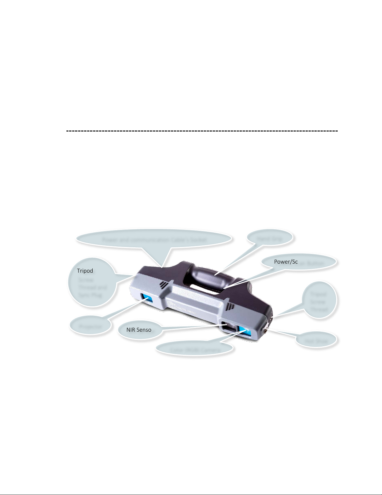
The F6 SMART™ Handheld 3D Camera
The handheld F6 SMART™ Camera combines two video cameras:
● A Color (RGB) Camera, and
● An Near-Infrared Camera (the NIR Sensor).
It also employs a laser-based infrared (IR) light emitter (the Projector).
The cameras and projector are mounted on the ends of an anodized aluminum dowel,
coated with an ergonomic rubberized hand grip.
Power and communication Cable’s Socket
Tripod
Screw
Thread and
Sync Plug
Projector
NIR Sensor
Tripod
Screw
Figure 2 – The F6 SMART™ Handheld 3D Camera
The Projector casts IR light (850nm in wavelength) onto the scene through a slide (mask)
containing Mantis Vision’s patented single-coded pattern.
The F6 SMART™ Camera has a working range of 60 cm to 4 m (24 " to 160").
The Power/Scan Button enables the user to power the device on and off as well as start
and stop scanning.
Page 20
3D Scanning Technology Overview
20
F6 SMART™ – Volumetric Handheld Camera – User Guide
Depth Sensor
(IR Camera)
Color (RGB)
Camera
The F6 SMART™ Camera has one socket (the power and communication connector) that
allows users to either connect it to a USB 3.0 port of the workstation, or charge its
battery by using a Power-Supply / Charger source.
The scanned images are stored on the workstation.
To operate the system, the F6 SMART™ Camera must be connected, via a USB 2.0 cable,
to a Windows-based workstation, on which the Echo™ application software is installed.
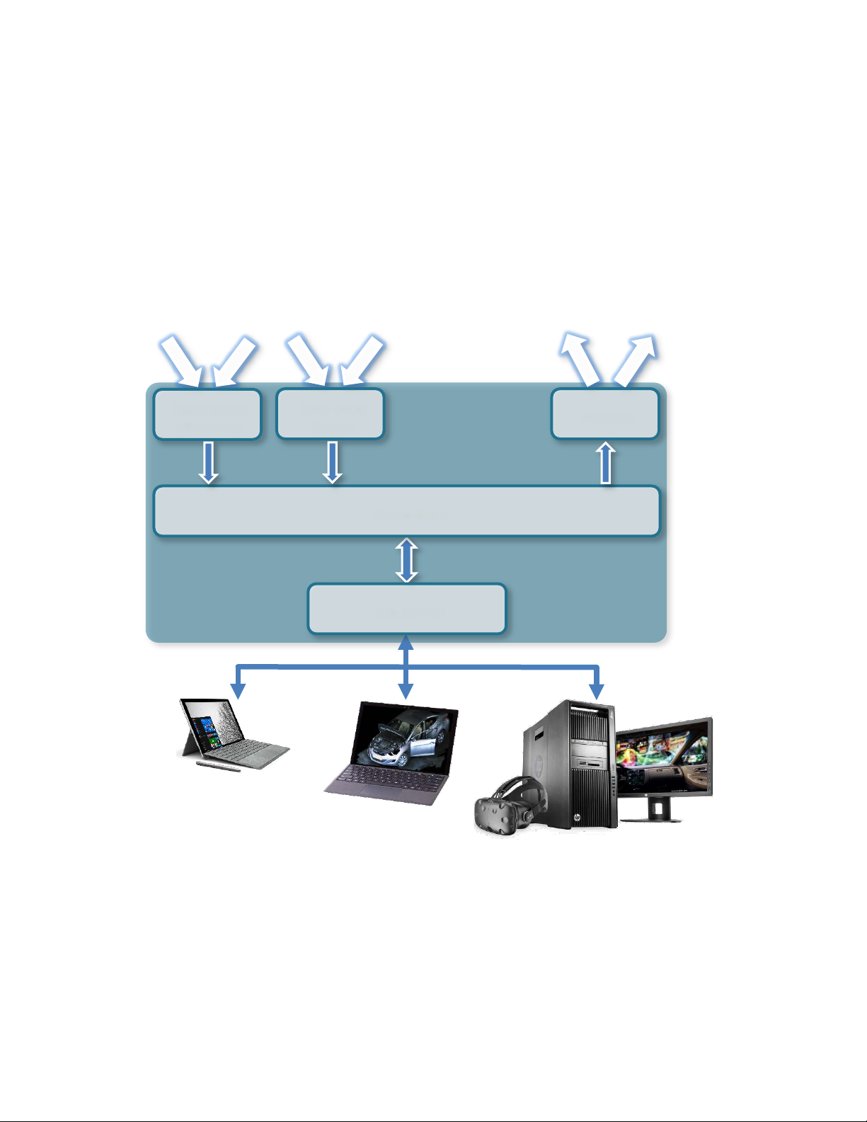
F6 SMART™ System Dataflow
Windows™ OS Devices
Driving Board
USB 2.0 Port
Projector
Figure 3 – F6 SMART™ System Dataflow
During acquisition, the video streams are recorded and processed on the workstation
while each video frame is decoded in real-time into a dense, color point-cloud of the
three-dimensional distance measurements (~ 60,000 points of data per frame). The
software automatically registers (aligns) the frames in the 3D video to recreate the 3D
geometry of the scene and its color information.
Page 21

3D Scanning Technology Overview
F6 SMART™ – Volumetric Handheld Camera – User Guide
21
Utilizing various tools in the software, users can work with and analyze the captured
scene, create 3D models of objects from the scene, and export them to 3D Computer
Aided Design (CAD) software applications for reverse engineering, manufacturing and
other applications.
Dimensions from the captured scenes can also be extracted using the advanced
measurement tool included in the software package.
The Echo™ Software
Mantis Vision’s Echo™ software optimizes the core sensing technology, by offering a full
3D processing pipeline.
This solution addresses depth sensing and processing needs such as auto-calibration,
high-quality registration, segmentation, Virtual-Reality / Mixed-Reality (VR/MR) shading,
and even data compression and streaming.
The result – any user can capture a static or dynamic object, person or scene of choice, in
different ambient light conditions and instantly edit, share and stream the real volumetric
content to any 2D/3D/MR/VR platform.
The Echo™ software serves, in fact, three (3) purposes:
● Control of the scanning processes.
● Editing of the scanned projects, including exporting its results.
● Setting up and configuring the equipment and software operation.
In other words – the scanning jobs could be done, in the field, with a light-weight laptop
where the Echo™ software is installed and serves as a control software for the scanning
operation, while the editing of the scanned results, up to the export of the outcoming
files, in the desired format, can be done on a workstation, where the very same Echo™
software is installed, and which serves as an editing station, in the office.
Page 22
The F6 SMART™ Kit
22
F6 SMART™ – Volumetric Handheld Camera – User Guide
Storage for workstation
and documentation
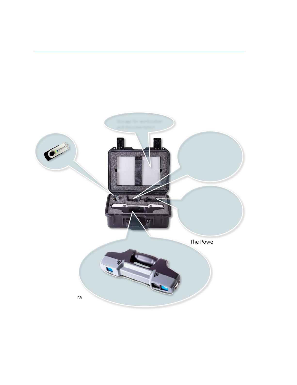
Chapter 4 The F6 SMART™ Kit
The F6 SMART™ System is shipped in a rugged plastic shipping case formed to contain:
● One (1) F6 SMART™ Camera
● One (1) USB Disk-on-Key Flash Drive
● One (1) special USB cable
● One (1) power supply
As presented in Figure 4 below.
The USB Flash Drive The USB Cable
The Power Supply
The
F6 SMART™ Camera
The shipping case also includes a cavity for storage of the workstation and
documentation.
Figure 4 – Content of the F6 SMART™ Kit
Page 23

The F6 SMART™ Kit
F6 SMART™ – Volumetric Handheld Camera – User Guide
23
NOTE:
Content of the USB Disk-on-Key Flash Drive is detailed in paragraph “Content of the USB
Disk-on-Key Flash Drive” on page 24 below.
The workstation (laptop) is not an integral part of the F6
SMART™ Kit.
Page 24

Installation of Echo™ Software
24
F6 SMART™ – Volumetric Handheld Camera – User Guide
SHOULD NOT
Chapter 5 Installation of Echo™ Software
The method of installing the Echo™ software resembles most other Windows™-based
applications’ installation processes and described thoroughly hereinafter.
NOTE:
During the process of installing the Echo™ software, the F6
SMART™ Camera
workstation!
be connected to the
Downloading the Latest Echo™ Software Version
The Echo™ software is encapsulated in the USB Flash Drive (Disk-on-Key) device included
in the F6 SMART™ Kit case (see Figure 4 on page 22 above).
It is suggested to check Mantis Vision’s website for availability of a more progressive
version.
If a more progressive version is available – download it onto the workstation for
installation instead of the USB-drive included version.
Content of the USB Disk-on-Key Flash Drive
The USB flash drive contains:
● The installation program –
●
Prerequisites
installation process.
●
Scanner Explicit Calibration Files
coloring.txt
config.ecfg
rig.txt
(RGB) Camera.
sub-directory containing a few directories and files associated with the
– a file containing calibration data for the Color (RGB) Camera.
– a file containing general F6 SMART™ configuration data.
– a file containing calibration data between the NIR Sensor and the Color
setup.exe
:
.
Page 25
F6 SMART™ – Volumetric Handheld Camera – User Guide
25
Installing the Echo™ Software
NOT
Installation of Echo™ Software
NOTE:
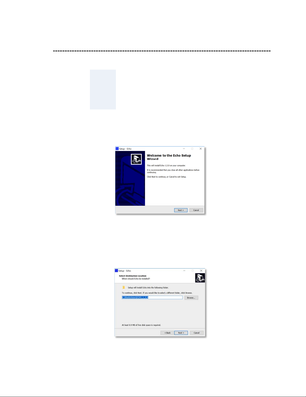
1. Double-click on the self-extracting installation file (
installation process. The “Welcome to the Echo Setup Wizard” Dialog-Box opens:
Prior to the installation of the Echo™ software, verify that the
workstation to be used meets the requirements detailed in
Table 3 in Appendix 2 on page 102 below) and that the F6
SMART™ Camera is
connected to the workstation.
Setup.exe
) to trigger the
Figure 5 – The “Welcome to the Echo Setup Wizard” Dialog-Box
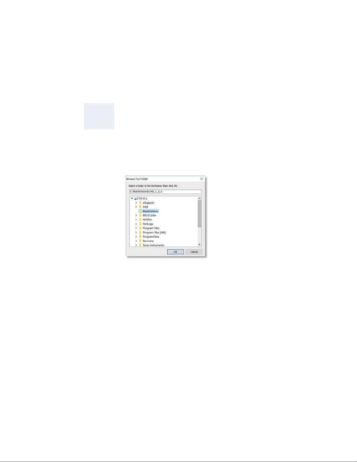
2. The
Cancel
install; click on the
Dialog-Box opens:
Command-Button allows immediate termination of the installation. To
Figure 6 – The “Select Destination Location” Dialog-Box
Next >
Command-Button. The “Select Destination Location”
Page 26
Installation of Echo™ Software
26
F6 SMART™ – Volumetric Handheld Camera – User Guide
This Dialog-Box allows manual settings of the folder where the Echo™ software
would be installed.
The default location is C:\MantisVision\ECHOxxx where xxx is the software version
number.
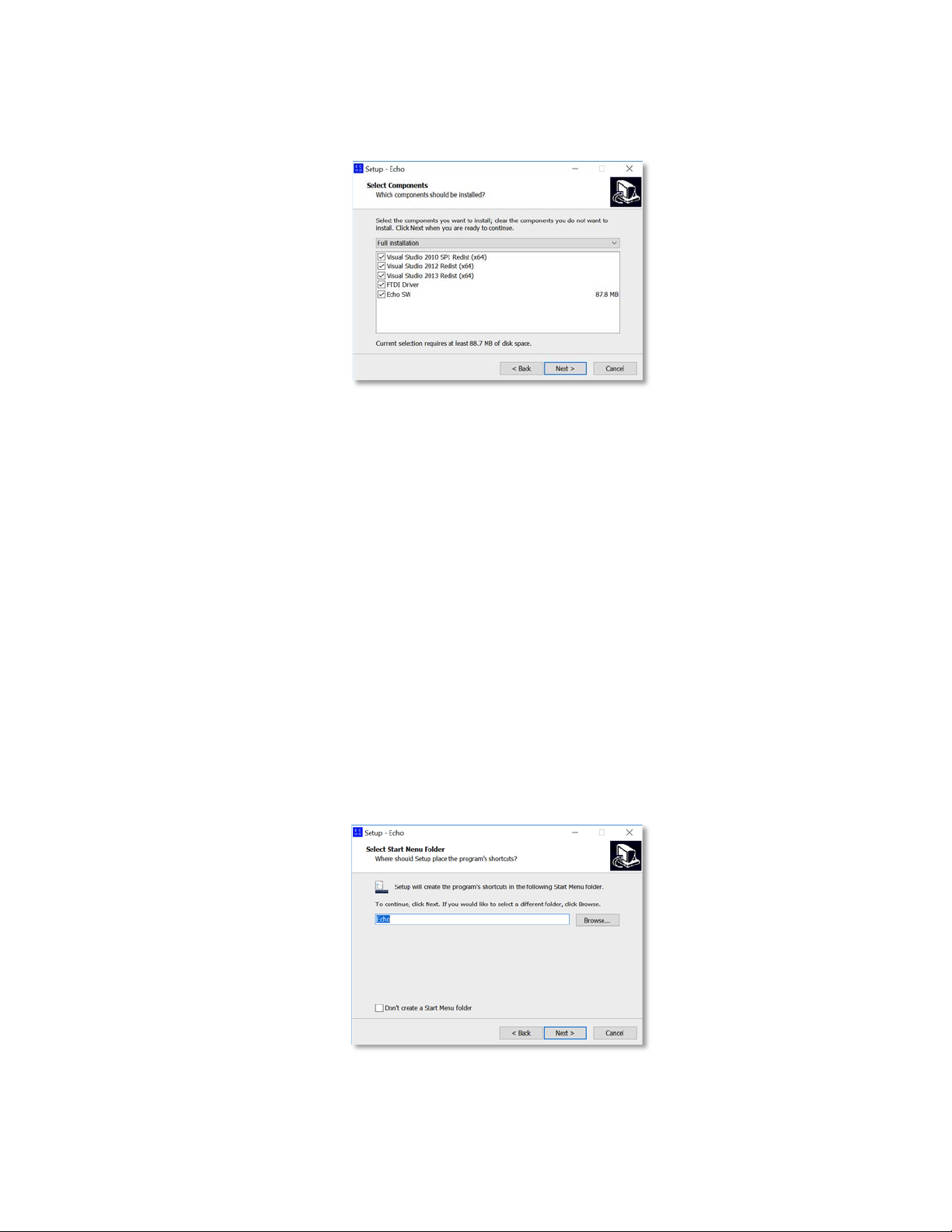
NOTE:
a. In case a different location is necessary, click on the
The “Browse For Folder” Dialog-Box opens:
It is recommended to preserve the default location to ease
the support tasks of this product.
Figure 7 – The “Browse For Folder” Dialog-Box
Browse…
Command-Button.
This Dialog-Box allows manual selection of another folder to install the Echo™
software onto, as well as setting-up a new folder.
Click on the OK Command-Button as soon as the installation folder is set, or on
the
Cancel
The “Browse For Folder” Dialog-Box closes and the “Select Destination Location”
Dialog-Box (see Figure 6 above) turns active again with the recently selected
installation directory presented in the address bar.
b. In case a step back in the installation process is required, click over the
Command-Button.
c. In case a termination of the installation is required, click over the
Command-Button.
3. To continue the installation, click on the
Command-Button to cancel the manual selection.
Next >
Command-Button.
Cancel
< Back
Page 27
Installation of Echo™ Software
F6 SMART™ – Volumetric Handheld Camera – User Guide
27
The “Select Components” Dialog-Box opens:
Figure 8 – The “Select Components” Dialog-Box
This Dialog-Box allows selection of which components (out of the options’ list) will be
installed.
♦ The
♦ The rest of the options (all are Microsoft™ Visual Studio™ Redistributable
The
Cancel
process, While the
installation process.
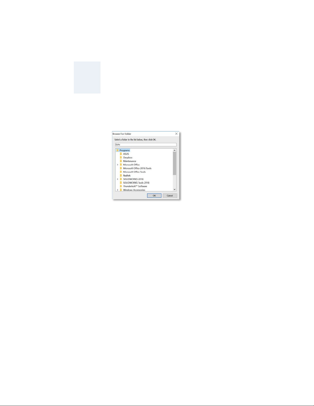
4. To continue the installation, click on the
Menu Folder” Dialog-Box opens:
Echo SW
installation.
Packages related) will be installed only if not found on the workstation’s
hard-disk.
Command-Button allows immediate termination of the installation
and
< Back
FTDI
(USB communication chip)
Command-Button revokes the previous step in the
Next >
Driver
are a MUST in this
Command-Button. The “Select Start
Figure 9 – The “Select Start Menu Folder” Dialog-Box
Page 28
Installation of Echo™ Software
28
F6 SMART™ – Volumetric Handheld Camera – User Guide
Start Menu’s default program name
Echo
This Dialog-Box creates the program’s shortcuts in Windows’s Start Menu.
NOTE:
a. In case a different name (or menu folder name) is required, click on the
Browse…
Explanations in this document, from this point onwards, will
refer to the
folder.
Command-Button to open another “Browse For Folder” Dialog-Box:
Figure 10 – The “Browse For Folder” Dialog-Box
(
) and
This Dialog-Box allows manual selection of another name and/or folder for the
installation of the Echo™ software, as well as setting-up a new name/folder.
Click on the OK Command-Button as soon as the installation name/folder is set,
or on the
The “Browse For Folder” Dialog-Box closes and the “Select Start Menu Folder”
Dialog-Box (see Figure 9 above) turns active again with the recently selected
installation name and folder presented in the address bar.
b. The “Select Start Menu Folder” Dialog-Box also allows complete elimination of
the Echo™ Strat Menu Folder by marking the “Don’t create a Start Menu folder”
Check-Box at the bottom-left side of the Dialog-Box.
c. In case a step back in the installation process is required, click over the
Command-Button.
d. In case a termination of the installation process is required, click over the
Command-Button.
5. To continue the installation, click on the
Cancel
Command-Button to cancel the manual selection.
Next >
Command-Button.
< Back
Cancel
Page 29
Installation of Echo™ Software
F6 SMART™ – Volumetric Handheld Camera – User Guide
29
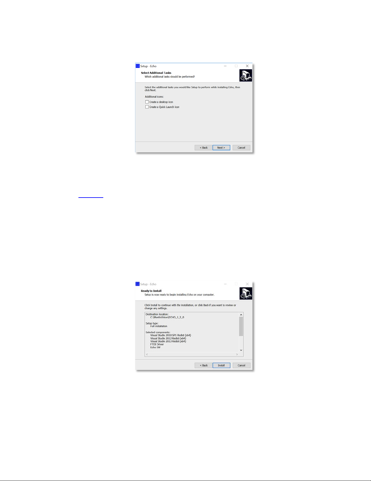
The “Select Additional Tasks” Dialog-Box opens:
Figure 11 – The “Select Additional Tasks” Dialog-Box
This Dialog-Box allows creation of a Desktop Icon and a Quick Launch Icon (in the
Task Bar, at the bottom of the screen, between the Windows™ Start Button and the
active programs), by marking the relevant check-box in the Dialog-Box.
Same as in previous Dialog-Boxes; the
previous Dialog-Box while the
Cancel
< Back
Command-Button is used to terminate the
installation process.
6. To continue the installation, click on the
The “Ready to Install” Dialog-Box opens:
Figure 12 – The “Ready to Install” Dialog-Box
Command-Button is used to invoke the
Next >
Command-Button.
This Dialog-Box details all previously provided installation parameters/components
for verification purpose.
Page 30
Installation of Echo™ Software
30
F6 SMART™ – Volumetric Handheld Camera – User Guide
As in previous Dialog-Boxes; the
previous Dialog-Box while the
< Back
Cancel
Command-Button is used to terminate the
installation process.
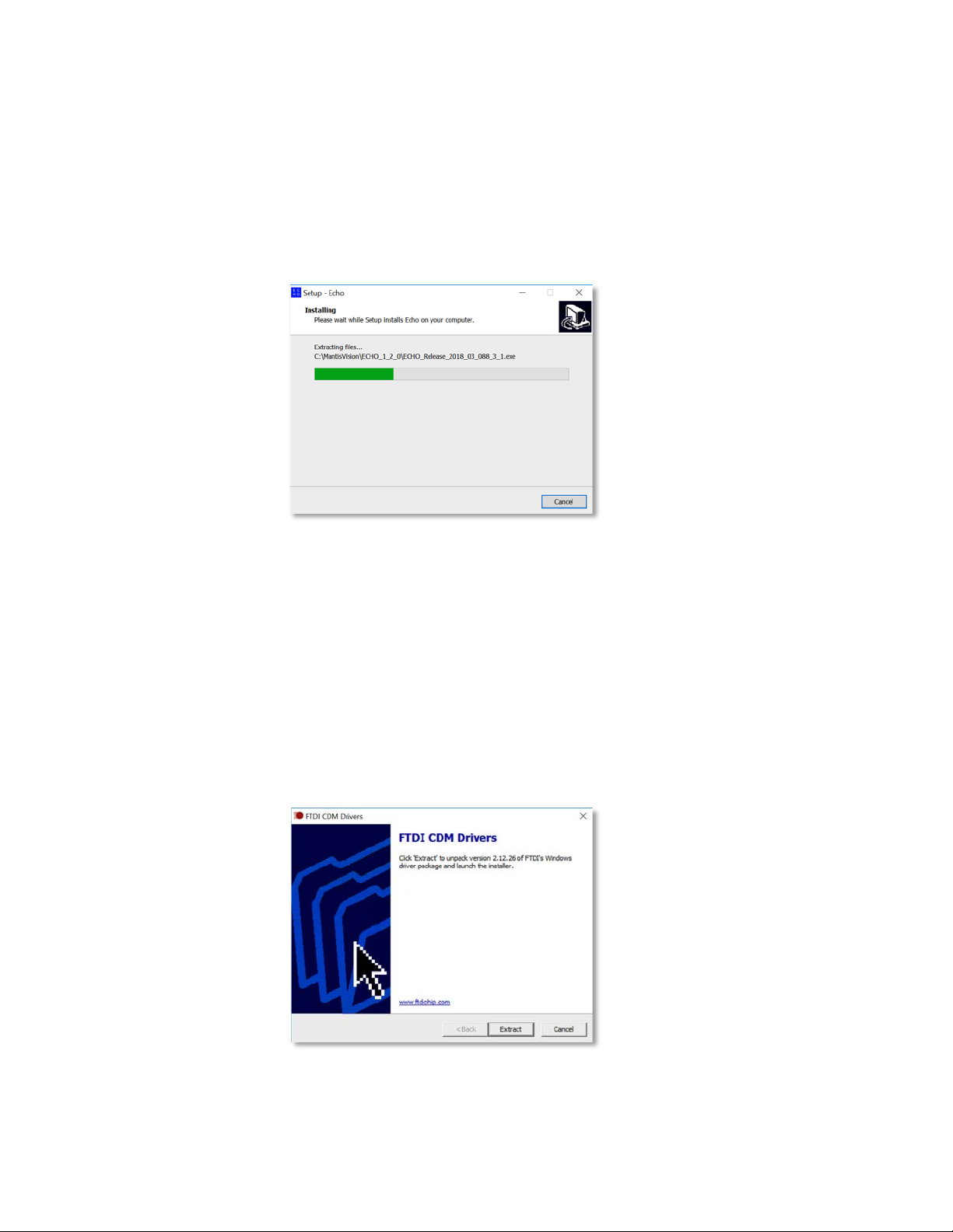
7. To continue the installation, click on the
The “Installing” Dialog-Box opens:
Figure 13 – The “Installing” Dialog-Box
Command-Button is used to invoke a
Install
Command-Button.
This Dialog-Box informs about the installation progress by presenting a Progress
Meter.
There is an option, during this step of the installation, to terminate the process by
clicking on the
Cancel
Command-Button.
If the FTDI Driver option was marked in the “Select Components” Dialog-Box (see
Figure 8 above), the FTDI CDM Drivers Dialog-Box will open during this installation
progress presentation:
Figure 14 – FTDI CDM Drivers Dialog-Box
Page 31

Installation of Echo™ Software
F6 SMART™ – Volumetric Handheld Camera – User Guide
31
The
the
Cancel
Extract
Command-Button terminates the FTDI Drivers’ installation process while
Command-Button allows extraction of the FDTI Drivers’ file required for
the installation.
The “Extracting Files” Dialog-Box opens to present, by means of a progress meter, the
progress of the extraction procedure.
Figure 15 – The “Extracting Files” Dialog-Box
As soon as the FTDI Drivers’ installation files are extracted and installed, the
“Welcome to the Device Driver Installation Wizard” Dialog-Box opens:
Figure 16 – The “Welcome to the Device Driver Installation Wizard” Dialog-Box
This Dialog-Box allows the installation of the recently extracted FTDI Device Drivers.
Click on the
Cancel
Drivers while a click on the
promotes the process to the next step of installing the Echo™ software.
8. Once the installation of the FTDI Drivers is complete, and with accordance to FTDI’s
Terms and Conditions, the drivers’ License Agreement Dialog-Box opens:
Command-Button terminates the installation of the FTDI Device
Next >
Command-Button allows the installation and thus
Page 32

Installation of Echo™ Software
32
F6 SMART™ – Volumetric Handheld Camera – User Guide
Figure 17 – The License Agreement Dialog-Box
In this Dialog-Box:
♦ FTDI’s License Agreement for the Device Drivers may be saved to a local
storage by clicking on the
on the
Print
Command-Button.
Save As
Command-Button, or printed by clicking
A copy of this License Agreement is attached to this document in Appendix
6 on page 113 below.
♦ There is a need to mark I accept this agreement (or I don’t accept this
agreement) radio-button.
Marking the I don’t accept this agreement button will cancel and
terminate the installation process.
♦ As soon as one of the above radio-buttons is marked, all three (3)
Command-Buttons at the bottom of the Dialog-Box turn active and allow:
▬ Invocation of the previous Dialog-Box, by clicking on the
Command-Button.
▬ Move to the next step of the installation process, by clicking over the
Next >
▬ Terminating and cancellation of the installation, by clicking over the
Cancel
9. Once the
Installation Wizard” Dialog-Box opens:
Next >
Command-Button.
Command-Button.
Command-Button is clicked upon, the “Completing the Device Driver
< Back
Page 33

Installation of Echo™ Software
F6 SMART™ – Volumetric Handheld Camera – User Guide
33
Figure 18 –The “Completing the Device Driver Installation Wizard” Dialog-Box
This Dialog-Box is provided for verification purposes only.
Clicking on the
Device Driver.
Clicking on the
procedure and the installation of the FTDI Device Drivers.
Progress of this process is displayed utilizing a Dialog-Box with a progress meter:
Figure 19 – Progress Meter of the Extraction and Installation of the FTDI Drivers
This Dialog-Box also allows:
Cancel
Finish
Command-Button terminates the installation of the FTDI
Command-Button completes the execution of the extraction
♦ Execution of the extraction procedure and installation of the FTDI Device
Drivers in the background by clicking on the
♦ Halting the progress of the extraction procedure and installation of the FTDI
Device Drivers by clicking on the
♦ Terminating the extraction procedure and installation of the FTDI Device
Drivers by clicking on the
Cancel
Background
Pause
Command-Button.
Command-Button.
Command-Button.
Page 34

Installation of Echo™ Software
34
F6 SMART™ – Volumetric Handheld Camera – User Guide
10. If no action is taken (none of the Command-Buttons mentioned above is clicked
upon) during the last installation step (9), the procedure of installing the Echo™
software ends up with the following “Completing the Echo Setup Wizard” Dialog-Box:
Figure 20 – The “Completing the Echo Setup Wizard” Dialog-Box
To conclude the installation of the Echo™ software, the workstation MUST be
restarted.
The decision whether to perform it straightaway or delay it for a later stage is left for
the installer by letting him mark one (1) of the two (2) following radio-buttons:
♦
♦
Followed by a click on the
Yes, restart the computer now
, or
No, I will restart the computer later
Finish
Command-Button.
.
Uninstalling the Echo™ Software
The procedure of uninstalling the Echo™ software is done in a similar way to the
uninstalling of any other Windows™ application program:
1. Click on the Control Panel Menu option from Windows’s Main Menu.
2. From the All Control Panel Items Window that opens, click on the Programs and
Features option.
3. Search for the Echo™ xxx (where xxx is the version number) line-item in the Programs
and Features window that opens and right-click on it with the mouse.
4. A roll-down menu opens. Click on the Uninstall option and follow the uninstall
procedure’s instructions provided therein.
Page 35

Installation of Echo™ Software
F6 SMART™ – Volumetric Handheld Camera – User Guide
35
\MantisVision
also delete the
Projects’ data files!
WARNING:
If the scanning data files’ repository was set within the
directory (see paragraph “Setting the
Database Repository” on page 36 below), uninstalling
the Echo™ software application will
Make sure these data files are backed-up prior to the
execution of an uninstall procedure.
Updating/Upgrading the Echo™ Software
WARNING:
Since complete removal of the Echo™ software
application also deletes the Projects’ data files,
update/upgrade of new versions need to be done as
explained on page 26, where each new version
installed under a separated directory, each carrying
the software version number.
Based on the assumption that settings of the Database Repository, as well as the
Calibration Files’ Repository, were executed, in the preceding installation, as described in
paragraph Setting the Database Repository (see page 36 below), the procedure of
updating/upgrading the Echo™ software is done in a similar way to the initial installation
of the Echo™ software (described in Chapter 5 – Installation of Echo™ Software on page
24 above), except that:
● There is no need to re-install the FTDI CDM Device Drivers (see page 27 above).
● There is no need to re-install the Visual Studio™ Redistributable Packages (see page
27 above).
● The Destination Location (see page 25 above) will be different since the software
version number is different (to the previously installed Echo™ software).
Page 36

Setting up the F6 SMART™ System
36
F6 SMART™ – Volumetric Handheld Camera – User Guide
Chapter 6 Setting up the F6 SMART™
System
Following the installation of the Echo™ software, there are three (3) more things to do to
make the F6 SMART™ System a complete and integrated working system:
1. Setting the Database Repository.
2. Connecting F6 SMART™ Camera to the Workstation.
3. Uploading the Calibration Files.
Setting the Database Repository
Upon initial activation of the Echo™ software, the following “First Start” Message-Box
opens to indicate that Database Repository is not set:
Figure 21 – The “First Start” Message-Box
If setting of the Database Repository is to be put off for a later stage, click on the
Command-Button.
To set the Database Repository click on the
The “Select Folder” Dialog-Box opens (see Figure 22 – The “Select Folder” Dialog-Box
below).
The “Select Folder” Dialog-Box allows selection of an existing directory (i.e.
C:\MantisVision\Database
follows:
1. Right-clicking over an empty space on the right window of the Select Folder Dialog-
Box.
2. Select the
3. Select the
New
option from the drop-down menu that opens.
Folder
) to be used as the repository, or, creation of a new one as
option from the drop-down sub-menu that opens.
Browse
Command-Button.
Quit
Page 37

Setting up the F6 SMART™ System
F6 SMART™ – Volumetric Handheld Camera – User Guide
37
C:\MantisVision
NOT
Database
Main Menu
Settings
Error! Reference source not found.
4. Type-in the new folder’s name and click on the
Figure 22 – The “Select Folder” Dialog-Box
TIP:
Use (or create) a repository location/directory within the Echo™
installation directory (
specific version included therein as these might be deleted
during removals of installations.
Select Folder
) but
Command-Button.
under any
In the example (see Figure 22 above), the repository was set to a
newly created directory called “
The new repository folder will be created and registered in the system as the default
repository for ALL scanning projects.
NOTE:
The process of setting the default repository for scanning
data may also be done (or modified) manually, at a later
stage, utilizing the Echo™
See paragraph “
Error! Bookmark not defined. Error! Reference source not
found..
’s
”.
option.
” on page
Page 38

Setting up the F6 SMART™ System
38
F6 SMART™ – Volumetric Handheld Camera – User Guide
Hierarchical Structure of the Database Repository
Following the setup of the Database Repository as recommended, the hierarchy tree of
the whole Echo™ installation on the workstation’s hard-disk would look like:
Figure 23 – Hierarchical Structure of the Database Repository
Connecting F6 SMART™ Camera to the Workstation
NOTE:
TIP:
Connect the cable included in the F6 SMART™ Kit (see Figure 4 – Content of the F6
SMART™ Kit on page 22 above) where:
This phase in the setup procedure need to be done while the
workstation is powered ON.
The electrical connection of the F6 SMART™ Camera to the
workstation is required now for the next steps of verification and
uploading the calibration files.
● The standard USB connector side is connected to a free USB socket of the
workstation, and,
Page 39

Setting up the F6 SMART™ System
F6 SMART™ – Volumetric Handheld Camera – User Guide
39
The red LED will only turn on following a USB protocol
● The 12-pin Bayonet-Lock Miniature connector – to the F6 SMART™ Camera (below
the Hand Grip).
Powering the F6 SMART™ Camera
Turn the F6 SMART™ Camera’s power ON by briefly holding down the Power/Scan Button
(inner side of the F6 SMART™ Camera’s Hand Grip) for 3-4 seconds until:
● The red LED indicator (at the outer top end of the Hand Grip) turns on, and,
● The workstation sounds a typical notification beep sound.
As per USB standard, the workstation will automatically identify the newly connected F6
SMART™ Camera and embed it into the workstation’s supported devices’ list.
NOTE:
handshake between the F6 SMART™ Camera and the
workstation.
The F6 SMART™ Camera will not power on with no proper
connection between the F6 SMART™ Camera and the
workstation.
Verification of Connection
One other type of verification to the connection between the F6 SMART™ Camera and
the workstation (on top of the above-mentioned LED) utilizes Window’s Device Manager
mechanism, as follows (see Figure 24 – Verification of F6 SMART™ Camera Connection
below).
1. Activate Windows’ Control Panel and select Device Manager from the menu.
The Device Manager Window opens (see Figure 24 below.)
2. Expand the Universal Serial Bus Controllers Directory and check to see that “
Serial Converter A
below) were added.
” and “
USB Serial Converter B
” items (highlighted in Figure 24
USB
Page 40

Setting up the F6 SMART™ System
40
F6 SMART™ – Volumetric Handheld Camera – User Guide
Figure 24 – Verification of F6 SMART™ Camera Connection
Uploading the Calibration Files
To complete the installation and setting up of the system for operation, one more step is
mandatory – the upload of the F6 SMART™ Camera’s explicit calibration files.
These are provided, from the manufacturing line, for EACH scanner device, following an
optical calibration procedure.
These calibration files are included in the USB Disk-on-Key Flash Drive, part of the F6
SMART™ Kit (see Chapter 4 – The F6 SMART™ Kit on page 22 above).
The calibration files are:
● The “
● The “
● The “
rig.txt
” – a file containing calibration data between the Projector and the NIR
Sensor.
coloring.txt
Color (RGB) Camera, and,
config.ecfg
” – a file containing calibration data between the NIR Sensor and the
” – a file containing general system calibration data.
Page 41

Setting up the F6 SMART™ System
F6 SMART™ – Volumetric Handheld Camera – User Guide
41
Calibration Files’ Repository
Same as with the Database Repository, there is a need to setup a repository for the
calibration files and the same rules applys – select (or create) a repository location within
the Echo™ installation directory (
versions included there as these might be deleted during removals of installations.
C:\MantisVision
) but NOT under any of the different
NOTE:
Since more than one F6 SMART™ Camera may be connected
to a single workstation, there will be more than one
Calibration Files’ Repository.
Uploading the Files
The process of uploading these calibration files is done as follows:
1. Activate the Echo™ software by clicking over its desktop icon (or Windows’ Main
Menu’s option) to invoke the Echo™ Main Screen.
2. Set the Echo™ software to Scan View Mode by clicking on the Scan Command-Button
in the Main Menu Bar:
Figure 25 – Scan Command-Button in the Echo™ Main Menu Bar
Since the calibration files are not uploaded yet, a “Recording Initialization Failed”
message box opens:
Figure 26 – The “Recording Initialization Failed!” Message-Box
Page 42

Setting up the F6 SMART™ System
42
F6 SMART™ – Volumetric Handheld Camera – User Guide
Click on the OK Command-Button to close the Message-Box.
3. Click on the Settings Command-Button at the bottom-left corner of the screen:
Figure 27 – the Settings Command-Button
4. The Settings Menu opens next to the Settings Command-Button:
Figure 28 – The Settings Menu
5. Click on the Camera Command-Button.
The Cameras Dialog-Box opens:
Figure 29 – The Cameras Dialog-Box
This Cameras Dialog-Box includes three (3) main parts:
Page 43

Setting up the F6 SMART™ System
F6 SMART™ – Volumetric Handheld Camera – User Guide
43
♦ A New bar with its associated Add path Command-Button, at the top.
♦ A center window listing all F6 SMART™ Cameras assigned to the
workstation.
♦ Three (3) Command-Buttons – Delete, Choose and Close.
For the initial uploading of the calibration files focus is made on the following steps
only. Other parts of this Dialog-Box are detailed in paragraph Settings Menu –
Camera Command-Button on page 51 below.
6. Type into the New bar a sub-directory name for storage of the calibration files of the
new F6 SMART™ Camera.
The new sub-directory’s name to be used should be the F6 SMART™ Camera’s
unique Serial Number (S/N).
This serial number can be found on the barcode label attached to the bottom end of
the F6 SMART™ Camera’s body:
Figure 30 – F6 SMART™ ID Barcode Label
7. Click on the Add path Command-Button.
The newly created sub-directory is added to the center window listing all F6 SMART™
Cameras assigned to the workstation.
8. Copy-paste the three (3) calibration files from the Flash Drive into this sub-directory.
9. Click on the newly added F6 SMART™ Camera name and then click on the Choose
Command-Button to set it as the system’s active F6 SMART™ Camera.
The Cameras Dialog-Box will close and the system has its F6 SMART™ Camera’s
calibration files uploaded and set for operation.
The initial setup of the system is completed.
Other setups will also be required for well-tuned scanning. These will be detailed
throughout the process of scanning below.
Page 44

Echo™ Software – Main Screen
44
F6 SMART™ – Volumetric Handheld Camera – User Guide
Chapter 7 Echo™ Software – Main Screen
Double clicking on the Echo™ icon, available on the workstation’s desktop (or its Quick
Launch Bar, pending parameters selected during installation; see page 29 above), will
launch the Echo™ software application.
The Echo™ is always launched with the Splash Screen presented in Figure 31 below:
Figure 31 – The Echo™ “Cover Page” Screen
The Splash Screen will be automatically followed by the Echo™ Main Screen which will
open, by default, in the Gallery View mode (see paragraph “Main Screen – Gallery View”
on page 46 below).
Foreword
The Echo™ Main Screen is the focal point for all scanning and editing operation of the
whole system. The Echo™ software’s navigation is performed by selecting one of the
three menu items (Command-Buttons) available in the Main Menu Bar:
● The Main Menu, ● The Scan View, ● The Gallery View
Page 45

Echo™ Software – Main Screen
45
F6 SMART™ – Volumetric Handheld Camera – User Guide
The Main Menu Bar
On the top-left corner of the Echo™ Main Screen resides the Main Menu Bar:
Figure 32 – The Main Menu Bar – Gallery View Active
The Main Menu Bar is common to all Echo™ screens.
NOTE:
The default Main Screen at Echo™ launch is the Gallery View.
Overview of the Main Screen – Gallery View
The Main Screen – Gallery View represents the scanning projects in a hierarchical fashion
where:
1. The Actions Window is, in fact, a Command-Button initiating new Projects.
2. Scanning Jobs of these Projects are detailed in the Projects’ Window. Under each of
these Projects’ Jobs there will be one or more:
♦ Raw Data Files – the originally scanned raw data files (point clouds, IR and
color RGB video), untouched, and
♦ Editable Data Files – the above files following the initial processing
procedures (Online Registration, HQ Registration, Edit and Merge, Global
Registration), and
♦ Spawn Data Files – the above files following Denoise and Meshing
processes.
These are all represented in Window’s File Explorer fashion.
Page 46

Echo™ Software – Main Screen
46
F6 SMART™ – Volumetric Handheld Camera – User Guide
The above can be described as follows:
Project 1
Project 2
Project 3 Raw Data Files File 1
File 2
File 3
Editable Data Files File A
File B
File C
Spawn Data Files File I
File II
File III
Figure 33 – Hierarchical, File Explorer Style Presentation
Main Screen – Gallery View
Figure 34 – Main Screen – Gallery View
Page 47

Echo™ Software – Main Screen
F6 SMART™ – Volumetric Handheld Camera – User Guide
47
The Main Screen – Gallery View include:
● The above-mentioned Main Menu Bar (see paragraph The Main Menu Bar on page
45 above) which controls the navigation between the three (3) main functions of the
Echo™ software.
● The View Control Bar which controls the views available in the Main Screen – Gallery
View, on the top-right end of the screen.
● The Actions Command-Button which activates/adds new projects processed by the
Echo™ software.
● The Projects Window which details each of the projects generated by the above-
mentioned Action Command-Button.
The View Control Menu Bar
The View Control Menu Bar is a Command-Buttons’ bar controlling the way Gallery View
is presented.
It has three Command-Buttons:
Figure 35 – The View Control Bar
● List View Command-Button
● Sort Command-Button, and
● Import Project Command-Button
The List View Command-Button
The List View Command-Button switches the display mode of the Gallery View between
the default thumbnail display and the classic file-list display (see Figure 36 below).
The button’s name is List View while in the default display mode of thumbnails and
changes to Icon View when in file-list view mode (see Figure 36 below):
Page 48

Echo™ Software – Main Screen
48
F6 SMART™ – Volumetric Handheld Camera – User Guide
Figure 36 – List View of the Main Screen’s Gallery View
The Sort Command-Button
The Sort Command-Button allows setting of a viewing mask where the
scanned/processed files are presented in a user-defined
The Actions Window
Figure 37 – The Actions Window
Page 49

Echo™ Software – Main Screen
F6 SMART™ – Volumetric Handheld Camera – User Guide
49
The Projects Window
Figure 38 – The Projects Window
Clicking on a project in the Projects Window, drills into the projects Data Files to
separately show their recorded evolution:
● Raw Data Files
● The Editable Data Files, and
● The Spawn Data Files.
Main Screen – Scan View
Selecting Scan View by clicking on the Main Menu Bar’s Scan Command-Button turns the
Echo™ software into the F6 SMART™ Camera control software thus allowing the scanning
operation:
Figure 39 – The Main Menu Bar – Scan View Active
Foreword
The Scan View represents the 2nd purpose of the Echo™ software – control of the
execution of 3D scan operations.
The purpose of scanning includes control of all possible viewing modes, control of the NIR
Sensor and the Color (RGB) Camera,
Page 50

Echo™ Software – Main Screen
50
F6 SMART™ – Volumetric Handheld Camera – User Guide
The Scanning Views Control Bar
The Scanning Views Control Bar controls and configures the five (5) different camera
viewing modes: IR, 2D, 3D, 3D+ and 3D Overview.
Figure 40 – The “Scanning Views” Control Bar
The Storage Meter
Figure 41 – The Storage Meter
The Switch to Full Screen Command-Button
Figure 42 – The Switch to Full Screen Command-Button
Page 51

Echo™ Software – Main Screen
F6 SMART™ – Volumetric Handheld Camera – User Guide
51
The Rotate View Command-Button
Figure 43 – The Rotate View Command-Button
The Settings Command-Button
The Settings Command-Button at the bottom-left side of the Main Screen – Scan View
screen activates the Setting Menu to enable control over the cameras and decoder.
Figure 44 – The Settings Command-Button
Clicking on the Settings Command-Button opens the Settings Menu.
The Settings Menu
Figure 45 – The Settings Menu
Settings Menu – Camera Command-Button
Clicking on the Settings Menu’s Camera Command-Button opens the Cameras Dialog-Box
discussed previously in paragraph “Uploading the Calibration Files” (see page 40 above).
Page 52

Echo™ Software – Main Screen
52
F6 SMART™ – Volumetric Handheld Camera – User Guide
Figure 46 – The Cameras Dialog-Box
The use of the New Bar and its associated Add path Command-Button for integration of a
new F6 SMART™ Camera to the system was discussed in the above-mentioned
paragraph.
The three (3) additional Command-Buttons at the bottom of this Dialog-Box are:
● The Delete Command-Button – used for deletion of previously added F6 SMART™
Cameras which are not further needed.
To delete such a F6 SMART™ Camera – select the F6 SMART™ Camera from the
Center Window by clicking on its name and click on the Delete Command-Button.
The F6 SMART™ Camera will disappear from the list in the Center Window and all its
associated calibration files will be deleted from the Calibration Files Repository.
NOTE:
Since the Echo™ software need to have at least one F6
SMART™ Camera defined in the F6 SMART™ System, the last
remaining F6 SMART™ Camera on the list cannot be deleted!
Page 53

Echo™ Software – Main Screen
F6 SMART™ – Volumetric Handheld Camera – User Guide
53
● The Choose Command-Button used for selecting a single F6 SMART™ Camera out of
the list of pre-set F6 SMART™ Camera provided in the Center Window.
To select a F6 SMART™ Camera off the list – click over the F6 SMART™ Camera’s
name to highlight it and then click over the Choose Command-Button to set it as the
system’s F6 SMART™ Camera.
NOTE:
● The Close Command-Button – used for closing the Cameras Dialog-Box and saving all
changes made with it.
The F6 SMART™ Camera will remain highlighted (and thus –
connected) as long as no other F6 SMART™ Camera replaces
it as the system’s F6 SMART™ Camera.
The Main Menu
Figure 47 – The Main Menu
Page 54

Scanner Views & Settings
54
F6 SMART™ – Volumetric Handheld Camera – User Guide
Chapter 8 Scanner Views & Settings
Foreword
There are five different camera viewing modes: IR, 2D, 3D, 3D+ and 3D Overview.
Infrared Red (NIR) camera View Mode
Use the IR mode to check Mantis Vision unique pattern on the object, the pattern should
cover as much territory as possible on an object and space as F6 decoder will turn only
the pattern covered areas to point cloud. Use the IR settings to adjust NIR camera to an
optimal configuration.
These are the IR settings, with Manual and Auto settings available. You can adjust the
Gain & Exposure according to light environment conditions The Laser Current can be
adjusted according to the device specs.
2D camera View Mode
The 2D camera mode is used for video capture during scanning, providing an image
projection of the object that you are scanning; this is the projection that will be available
for mesh textures.
Page 55

Scanner Views & Settings
F6 SMART™ – Volumetric Handheld Camera – User Guide
55
The color camera affects the quality of the mesh texture, not
of the data.
White Balance
There are Manual and Auto settings for 2D Color. Use the Manual mode to adjust the
Exposure (the amount of light) and Gain (the amount of signal amplification).
To perform White Balance - the process of removing unrealistic color casts, so that
objects which appear white in person are rendered white in your photo - point the
scanner to a white wall or blank sheet of paper and click on the White Balance button.
This is especially important when working outdoors, as the scanner must consider the
"color temperature" of the light source, i.e. the relative warmth or coolness
of white light.
NOTE:
3D Single Frame View Mode
In the 3D camera mode, you will see the point cloud decoding of a single frame. F6 single
frame may contain approximately ~70,000 points with a field of diagonal view 80 °
3D+ Multi Frame View Mode
The 3D+ camera mode is used for online registration (real time model stitching), showing
the correct frame + all other frame which decoded during scanning.
We recommend remaining in this mode when performing and viewing scanning, this
mode will help you understand if your scene is still registered or broken for more
segments.
When losing registration 3D+ view will start new group of segmentation and frame
registration will start again.
Page 56

Scanner Views & Settings
56
F6 SMART™ – Volumetric Handheld Camera – User Guide
Overview 3D model View Mode
The 3D Overview mode provides a real-time view of the model being built.
Additional camera angle of the online registration, you can rotate the model during the
canning process to see the model been built and to see where you are missing data to
complete it during your scanning.
Users can use this mode to check their scanning object status, and in case they are
finding missing data they can go back and complete it by scanning the missing area.
Page 57

MVX - Rendering Configuration
F6 SMART™ – Volumetric Handheld Camera – User Guide
57
Chapter 9 MVX - Rendering Configuration
Foreword
In this chapter, we will show you how to configure MVX and Rendering, and explain how
to switch to full screen view and rotate the camera angle view.
MVX Configuration
Raw MVX is the proprietary Mantis Vision Echo scanning file format. RAW MVX serves as
a “container” that embeds the different scan layers - 2D, 3D and video (IR and color) as
well as the embedded and rig files.
MVX settings include frames per second and Data Layer settings.
We recommend scanning at 8 fps.
These are the default Data Layer settings.
If you are working with a less powerful computer, by disabling 3D Point Cloud and/or Live
Registration, less memory and system resources are required.
Page 58

MVX - Rendering Configuration
58
F6 SMART™ – Volumetric Handheld Camera – User Guide
Rendering Configuration
Click on Rendering to define the post-scan rendering viewer configuration. Use the
available sliders to adjust the point cloud intensity (brightness) and saturation (distance
from being neutral/pure gray), and zoom the particle size and camera distance.
Switch to Full-screen During Scanning
To enter Fullscreen view, click on the following button in the upper right-hand corner of
the screen.
Click again to exit Fullscreen view.
Rotate Camera Angle View
To rotate the camera angle view, click on the following button at the bottom right-hand
corner of the screen.
Page 59

Starting a New Project
F6 SMART™ – Volumetric Handheld Camera – User Guide
59
If you do not create a new project before starting, scans will
Chapter 10 Starting a New Project
Foreword
In this chapter, we introduce the proper workflow for a new scan, including creating a
new project, start/stop recording and exporting a project.
Creating a New Project
The first thing to do before scanning is to create/name a new project. This organizes your
project scans, edits and spawns into one repository. All scans are first saved as RAW files,
after which they can be edited and spawned.
NOTE:
be unattached without any definitions or organizational
hierarchy, so make sure not to skip this important step.
Page 60

Starting a New Project
60
F6 SMART™ – Volumetric Handheld Camera – User Guide
Start/Stop Recording
With the F6 SMART scanner connected to the computer via the USB communication
cable, enter the Scan mode.
There are two ways to begin scanning:
briefly hold down the Scan (Power) button on the F6 SMART scanner, or
click the round Record button in the middle-left of the screen. It will turn red to
indicate that scanning has been started.
To end scanning, either click on the red Recording button, or briefly hold down the F6
SMART Record (Power) button.
Page 61

Starting a New Project
F6 SMART™ – Volumetric Handheld Camera – User Guide
61
Exporting a Project
In Gallery mode, right-click on the project that you want to export. Click on Export a
Project.
You will then see the following screen, in which you are asked to browse the file location
and give a name to the exported (.db) file.
See Chapter Nine for details on how to import a new project.
Page 62

Starting a New Project
62
F6 SMART™ – Volumetric Handheld Camera – User Guide
Exporting as an MVX
When exporting to the MVX file format, select MVX from the file format type. The default
MVX Export Settings will show Merge Frames Within Groups as deselected. This is
because MVX is the native file format inside of the Echo software, and it already
recognizes all groups and segments of the scan. If you do not deselect Merge Frames
Within Groups, it will not be possible to edit the MVX later.
All other actions for saving the exported scan are the same.
Exporting a Point Cloud
The Echo software lets you export your scanning data point cloud to numerous file
formats. Outside of the proprietary Mantis Vision MVX format, supported file formats
include:
.ply point cloud & ply mesh (color data & texture)
.obj (color data & texture)
.e57 point cloud (color data)
.pts point cloud (color data)
.xyz point cloud (color data)
.stl (color data & texture)
Page 63

Starting a New Project
F6 SMART™ – Volumetric Handheld Camera – User Guide
63
To Export point cloud, go to Menu Export chose file format, you can chose
exporting each file format as frame by frame or multi frame.
Export MP4
Echo allow you to export video taking during scanning process.
To Export point cloud, go to Menu Export chose file format
Page 64

Import MVX / MPC
64
F6 SMART™ – Volumetric Handheld Camera – User Guide
Chapter 11 Import MVX / MPC
Foreword
In this chapter, we show you how to import MVX, MPC and project files.
MPC is the previews Mantis-Vision unique file format.
Importing an MVX File
To import an MVX file, begin by creating a new project. Next, click on the Import MVX
button, select the file from its location and then click Open.
Page 65

Import MVX / MPC
F6 SMART™ – Volumetric Handheld Camera – User Guide
65
Importing an MPC File
To import an MPC file, begin by creating a new project. Next, click on the Import MPC
button, select the file location and then click Open. Please note that although you will be
able to apply the advanced editing tools available inside the Echo software app, currently
it is not possible to create a mesh with texture.
Importing a Project Folder
To import a project, click on Import Project from the Gallery home screen. Select the
project folder then click Open.
Page 66

Navigate
66
F6 SMART™ – Volumetric Handheld Camera – User Guide
Please note that the F6 SMART scanning data is not aligned
Chapter 12 Navigate
Foreword
In this chapter, we show you how to rotate, drag and zoom objects using mouse options
when viewing a scan in the 3D viewing mode. As this is a 3D scan, rotation can be done
along the X, Y and Z axes.
NOTE:
X Axis Rotation
Click on the image, and while holding down left the mouse button slide the mouse
horizontally
Y Axis Rotation
Click on the image, and while holding down the mouse button slide the mouse vertically.
Page 67

Navigate
F6 SMART™ – Volumetric Handheld Camera – User Guide
67
Drag
Click on the image. While holding down both the left and right mouse buttons, drag it to
the desired position.
Zoom In/Out
Click on the image, and while holding down the mouse button use the scroll wheel to
zoom in and zoom out on the image.
Page 68

Post Scan Editing Tools
68
F6 SMART™ – Volumetric Handheld Camera – User Guide
Chapter 13 Post Scan Editing Tools
Foreword
In this chapter, we show you how to use the advanced editing tools built into the Echo
software application. This includes registration, rendering, projection, widgets, views and
backgrounds.
HQ (High quality) Registration
When editing your scan, we recommend that you first click on HQ Registration. HQ
Registration is an algorithm layer that that corrects the misalignment that occurs during
the scanning decoding process. Even if there is no visible misalignment, we recommend
performing HQ Registration after every scan.
In case fixing misalignment… will not work the HQ registration will bark the segment
group to more groups
Rendering Mode
The Rendering Mode helps find the proper blend between the geometry and texture of
the scan. Sliders are used adjust the point intensity, point size and point saturation.
Page 69

Post Scan Editing Tools
F6 SMART™ – Volumetric Handheld Camera – User Guide
69
To use these Projection Modes properly, first align the
Projection Mode
There are four options in Projection Mode: Perspective, Perspective Direction,
Orthogonal and Top/Left/Right.
NOTE:
scan to ground using the Ground widget
Background Mode
Use Background Mode to select your desired background view.
Click Custom to define your own background color. Click on the desired color, or create
your own color using the Color/Hue/Saturation sliders, then click Go.
Page 70

Post Scan Editing Tools
70
F6 SMART™ – Volumetric Handheld Camera – User Guide
Widgets
Available widgets include Ground and Center of Rotation
Ground
Setting the Ground plane helps simplify your work in the 3D environment. Select the
desired scan from the Gallery to open it in the Compose mode.
Click on the Edit button to select the segment. Then click on the Ground widget.
Click once to select the ground and click again to remove the ground from view. To
define the ground, hold down the left and right mouse buttons to drag the image. Along
with the Shift button, the ground plane will move as well.
Page 71

Post Scan Editing Tools
F6 SMART™ – Volumetric Handheld Camera – User Guide
71
Center of Rotation
Defining the Center of Rotation helps find the optimal rotation between the points.
To use the center of rotation press Ctrl + right+left mouse.
Center View
Clicking on the Center View icon takes you to the exact center point of the scan.
Page 72

Selection Tools
72
F6 SMART™ – Volumetric Handheld Camera – User Guide
Chapter 14 Selection Tools
Foreword
In this chapter, we show you the broad array of Selection Tools available in the Echo app.
These include Rectangle, Spray Brush, Free Draw, Cylinder + Ground, Invert, Accuracy,
Range, Deselect, Original Colors, Decimation, Mark for Registration, Delete Selection and
Scan Viewer options.
After clicking on a tool to select it, it will appear (highlighted in blue) where the Selection
Tools icon is situated. For example, here is the Rectangle Selection Tool after it has been
selected.
Rectangle
Use the Rectangle Selection Tool to select a rectangular area of the scan for deletion.
After clicking on the Rectangle Selection Tool, highlight the area that you want to delete
and then click on the Delete button to the left.
Page 73

Selection Tools
F6 SMART™ – Volumetric Handheld Camera – User Guide
73
Spray Brush
Use the Spray Brush Selection Tool to selectively “spray” certain areas of the scan for
deletion.
After clicking on the Spray Brush Selection Tool, spray the area you want to delete and
then click on the Delete button.
Page 74

Selection Tools
74
F6 SMART™ – Volumetric Handheld Camera – User Guide
Free Draw
Use the Free Draw Selection Tool to free draw a shape to delete a uniquely shaped area
of the scan for deletion.
After clicking on the Free Draw Selection Tool, draw on the area you want to delete and
then click on the Delete button.
Cylinder
The Cylinder Selection Tool is used to highlight a cylindrical area of a scan for deletion.
This is useful, for example, to highlight a standing person in a room.
After clicking on the Cylinder Selection Tool, draw a cylinder on the area you want to
delete and then click on the Delete button.
Invert
Invert is used to highlight the entire scan in red. This is useful to see how the scan
appears after using the aforementioned tools to delete certain sections.
Page 75

Selection Tools
F6 SMART™ – Volumetric Handheld Camera – User Guide
75
Accuracy
Accuracy tool selects points by their accuracy level across percentage range on the
accuracy bar, this option allows removing inaccurate points and removing them from
scene. After selecting the accuracy range approve your selection.
Range
Use the Range tool to adjust the distance of the points that appear post-scan. Begin by
clicking on the Range Selection Tool:
After clicking on Range, the following screen appears:
Page 76

Selection Tools
76
F6 SMART™ – Volumetric Handheld Camera – User Guide
Use the slider to adjust the point viewing range from a minimum of 400 mm to a
maximum of 4500 mm, F6 Smart effective range.
Deselect
Use the Deselect Selection Tool to undo the selection you have made using other
selection tools.
Undo/Redo
Use the Undo button to undo the most recent action.
Page 77

Selection Tools
F6 SMART™ – Volumetric Handheld Camera – User Guide
77
Delete Selection
After using one of the above Selection Tools, click on Delete Selection to remove the
highlighted selection.
Original Colors
Original Colors shows the scan view with its original color perspective. Clicking again on
the Original Colors button converts the scan segments to a representative color for each
group, this is additional relation to a specific segment while editing it.
Page 78

Scan Viewer - Timeline
78
F6 SMART™ – Volumetric Handheld Camera – User Guide
Chapter 15 Scan Viewer - Timeline
Foreword
Echo editor based on time line, as each of the take taking by F6 Smart contains 2D/ color
video as well as decoded point cloud. In this chapter we will elaborate on the deferent
decoded preview modes based on the scene timeline.
Single Frame
View an individual frame of the scan.
Shadow Frame
Provides a shadow view of an individual frame.
Page 79

Scan Viewer - Timeline
F6 SMART™ – Volumetric Handheld Camera – User Guide
79
All Frames
Shows the scan in its entirety.
Cumulative View
show the scan being constructed frame by frame. Use this view to check for
misalignments in scene.
Play/Pause
Click to play the entire scan recording. This is a toggle button with Pause. The view is a
function of the Frame View that you have selected.
Page 80

Scan Viewer - Timeline
80
F6 SMART™ – Volumetric Handheld Camera – User Guide
Next/Previous Frame
Takes you to the next frame.
Magnet
Magnet the preview screen to the camera angle for both 2D and 3D view.
Page 81

Scan Viewer - Timeline
F6 SMART™ – Volumetric Handheld Camera – User Guide
81
Highlight
Highlighted the correct camera frame at the time of scanned, move the timeline to see
the current camera frame.
Page 82

Measurement Tools
82
F6 SMART™ – Volumetric Handheld Camera – User Guide
Chapter 16 Measurement Tools
Foreword
In this chapter, we show you the range of Measurement Tools available in the Echo app.
These include Point, Distance, Angle, Point to Plane, Point to Line and Line to Line.
Measurements are recorded and available for viewing in the Measurement History.
Point
Click on the Point tool, which will then appear highlighted in blue next to the scan.
Double-click on the point you want to measure to mark it for measurement. The XYZ
coordinates will appear above the point.
The point position and XYZ coordinates appear in the Measurement History.
Page 83

Measurement Tools
F6 SMART™ – Volumetric Handheld Camera – User Guide
83
Distance
To measure the distance between two points, click on the Distance button, which will
then appear highlighted in blue next to the scan. Double-click on the first point location,
then double-click on the second point location. The distance between the two points
appears in the Measurement History.
Angle
To measure an angle, click on the Angle button, which will then be highlighted in blue
next to the scan. Double click on the first location, then double-click on the second
location; green X’s appear at each of the two points. The angle between the two points
appears in the Measurement History.
Point to Plane
To measure the distance between a point and a plane, click on the Point to Plane button,
which will then be highlighted in blue next to the scan. Double click on the first location,
then double-click on the second location and again on the third location. The angular
point vertex will be shown. When you double-click a fourth time, the distance from the
point to the plane appears in the Measurement History.
Point to Line
To measure the distance between a point and a line, click on the Point to Line button,
which will then be highlighted in blue next to the scan. Double click on the first location,
then double-click on the second location to create the line. When you double-click a third
time to mark the point, the distance from the point to the line appears in the
Measurement History.
Page 84

Measurement Tools
84
F6 SMART™ – Volumetric Handheld Camera – User Guide
Line to Line
To measure the distance between two lines, click on the Line to Line button, which will
then be highlighted in blue next to the scan. Double click on the first location, then
double-click on the second location to create the first line. Double-click again to mark the
first point of the second line, and one final time to create the second line. The distance
between the two lines appears in the Measurement History.
Measurement History
Clicking on the Close button closes the measurement that you were performing, saving it
in the Measurement History. Conversely, clicking on Clear clears the entire Measurement
History.
Page 85

Segments
F6 SMART™ – Volumetric Handheld Camera – User Guide
85
Chapter 17 Segments
Foreword
In this chapter, we show you how to work with segments. Segments are portions of a
scan - a single frame or a number of frames - that are missing data in the flow and
therefore do not succeed in connecting to the main scene.
If Allow Multi-segment is enabled in the Settings of the Main Menu, then depending on
the scanning environment, your scan may or may not contain multiple segments. The
Echo software decodes the scan and assembles the 2D and 3D scan data as coherently as
possible.
HQ (High quality) Registration
High quality registration is a progress recommend performing after scanning completion,
this is a complementary process for the online registration which taking place during
scanning.
HQ registration performing – Sequential, segment and global registration, in order to fix
misalignments and connect unattached segments based on object geometry. The process
can take several minutes, depending on the number of frames and the number of points
Remove Registration
Removing Sequential registration from Raw files after online registration. Using remove registration allow
users to break existing registration to start register again as HQ registration.
Page 86

Segments
86
F6 SMART™ – Volumetric Handheld Camera – User Guide
Delete small Segments
Use Cleanup Segments to delete segments containing a minimal number of frames that do not connect to
the main scene. After clicking on delete small segments, define the minimum number of frames for
segments that you want to remove, then click Go. Any complying segments will be deleted.
The maximum value will be group with highest amount of frames.
Split Segments
If you want to split a scan into multiple segments, open the scan for editing , Go to the
scan timeline at the bottom of the screen, right-click the mouse at the position that you
want to split, then click on Split Segment, make sure time line handle is at the same
frame location
use case – when misalignment in the registration is spotted, change to cumulative view
to verify the actual misaligned frame(see figure 102) use split segment on the misaligned
frame, this action will split the segment into 2 separated segments in their original group,
in order to ungroup the chosen segment press on the “ungroup” icon- this will create a
new group with new segment.
Page 87

Segments
F6 SMART™ – Volumetric Handheld Camera – User Guide
87
Group
Each group will contain joined and merged registrated segments, that will help editing
the scanned point cloud.
group hierarchy – image (only)
1. Edit
2. Checking Box
3. Merge
4. Ungroup
5. Visible
6. Delete
Group tab management
Under each group the following options are available:
It is possible hide/show each group/segment individually by pressing on the eye icon
(toggle visible) next to the relevant segment group
It is possible to delete the entire group or either delete each of the segments by pressing
on the delete icon next to it- this action will delete the group/segment indefinitely
To view or edit only the chosen group press on the pencil icon, once pressed you will be
able to manipulate the chosen point cloud data in the 3D space and only the relevant
timeline will be displayed
It is possible to split grouped segments by pressing the ungroup button (2 squares icon),
this will divide the segments inside the group to multiple groups.
Page 88

Segments
88
F6 SMART™ – Volumetric Handheld Camera – User Guide
Merge Groups
It is possible to force groups into registration, this can be done by checking the relevant
groups and press on merge groups in Group Action Buttons.
To merge groups, two groups must be selected first.
Merge segments within Groups
To Merge segments within Groups, select the frames that you want to merge, then click
Merge Frames within Groups.
To merge few segments into a group, select the relevant segments by checking the box
next to their frame count and then press merge next to the total frame count. (when one
or less segments will be checked the merge, option will be grayed out).
Page 89

Segments
F6 SMART™ – Volumetric Handheld Camera – User Guide
89
Manual registration
to registrar manually between 2 groups, manipulate them into overlapping geometry
while pressing the edit icon on the relevant group and manipulate it with the following
actions:
To rotate the scene (change its perspective), hold down the left mouse button
while moving the mouse.
To rotate the scene around an axis, hold down the right mouse while moving the
mouse.
To zoom in/out use the mouse wheel.
To zoom in/out only one group hold down the left mouse button + Ctrl while
moving the mouse.
To move/pan (translate), hold down the left and right mouse buttons while
moving the mouse.
After aligning two segments together, press the check box of the 2 relevant groups and
press Manual.
once the registration has passed correctly the two groups will merge into one, if there is
not enough alignment/overlapping geometry and the registration is not optimal you will
get the following message: ‘registration is not optimal’
Decide whether you are sufficient with the result and then press register or press cancel
to have another attempt.
For a color view of different groups press original colors to have different color for each
group, the color is also shown near the group name.
Page 90

Segments
90
F6 SMART™ – Volumetric Handheld Camera – User Guide
Automatic
Automatic registration performing, segment registration. Register multi groups without
segment alignment.
Global Registration
Global Registration has always been one of the most resource-intensive operations in
data processing. This algorithm converts all 3D frames (or shots taken during scanning)
into a single coordinate system using information on the frames’ positions relative to
each other. Each frame is registered in the global coordinate system. uses both the
geometry and texture of the object to find the optimal position of each frame, we ensure
the highest accuracy of positioning and fix misalignment that hard to spot by the naked
eye. Global registration can be performed on one group of segments only, so please
make sure to register and align all segments to one group before running global
registration.
Page 91

Denoise - Noise Removal
F6 SMART™ – Volumetric Handheld Camera – User Guide
91
Chapter 18 Denoise - Noise Removal
Foreword
In this chapter, we show you to use the available Denoise tools. Denoising is used to
remove sparse statistical outliers that can distort a point cloud in 3D scanning. There are
two Denoise algorithm options in the Echo software: MLS and SOR. You can use both
Denoising tools simultaneously, though it will take more time to process the model.
Each of the existing algorithm work in a different way and may serve a different propose.
NOTE:
Denoising option will start functioning only after all scene
groups merged in to one group only
Cleaning algorithm – SOR (Statistical Outlier Removal)
Statistical Outlier Removal of the PCL library. It computes first the average distance of
each point to its neighbors, then it rejects the points that are farther than the average
distance plus a number of times the standard deviation (second parameter).
Page 92

Denoise - Noise Removal
92
F6 SMART™ – Volumetric Handheld Camera – User Guide
SOR Outlier Coefficient
SOR perform as a noise cleaner by outlier coefficient, outlier is an observation point that
is distant from other observations. An outlier may be due to variability in the
measurement excluded from the data set.
the coefficient parameter removes outlier points based on distance from the tangent
plane, and doesn't change the position of existing points.
SOR outlier coefficient bar work as 1 will be closest to target and 10 will be farther to
target, for large scale scanning such as rooms it is better to use far number such as 6 or 8
as noise point will be far from plane.
Smoothing algorithm - MLS (Moving Least Squares)
Moving least squares is a method of reconstructing continuous functions from a set of
unorganized point samples via the calculation of a weighted least squares measure
biased towards the region around the point at which the reconstructed value is
requested.
Moving least squares method is useful for reconstructing a surface from a set of points,
by finding the average of the center, often it is used to create a 3D surface from a point
cloud through either down sampling or up sampling. MLS algorithm fits the
neighborhood of each point to a surface and projects the point on it.
MLS is not removing points but find a closest surface to each point and bring it closer to
the center of the surface and by that its smoothing the point cloud for a sharper mesh
results.
MLS Radius search
To approximate the point to surface defined by a local neighborhood of points p1, p2 …
pk at a point q we use a bivariate polynomial height function defined on a on a robustly
computed reference plane, the distance from those planes is the radius of the point
interpolation being performed.
Page 93

Spawn
F6 SMART™ – Volumetric Handheld Camera – User Guide
93
Chapter 19 Spawn
Foreword
Spawning is the creation of a new child process. This is done by calling an operating
system function, and the OS does all the work of setting up the new process, and
managing it along with all the other processes currently running. In Echo when you can
choose to spawn a file in ether mesh or point cloud, this new file will no longer contains
MVX file content such as RGB / IR video and rig data but will remain point cloud
coordinate system.
To create a spawn file, click on the spawning icon than name the new spawn file you
want to create.
Chose the type of spawn file you like create – Mesh or Point Cloud.
Mesh
While point clouds can be directly rendered and inspected, point clouds are often
converted to polygon mesh or triangle mesh models, NURBS surface models, or CAD
models through a process commonly referred to as surface reconstruction.
There are many techniques for converting a point cloud to a 3D surface. Mantis-Vision
approaches for mesh, is to convert the point cloud into a volumetric distance field and
reconstruct the implicit surface so defined through a marching cubes algorithm.
Point clouds can also be used to represent volumetric data, as is sometimes done in
AR/VR imaging. Using point clouds, multi-sampling and data compression can be
achieved.
In this chapter, we show you how to spawn scans inside the Echo app.
Page 94

Spawn
94
F6 SMART™ – Volumetric Handheld Camera – User Guide
Meshing method -
In Echo we use Poisson Surface Reconstruction algorithm to convert point cloud to mesh
surfaces. Surface reconstruction, can only take place on a point cloud with normal and to
obtain good results, the normals of the cloud must be clean, correct/consistent and not
too noisy.
Mesh options
Tex tured
In Echo there are two ways to use F6 smart color camera for texturing your scanned
object:
Image projection mesh - UV mapping using F6 smart RGB camera output. This process of
projecting a 2D image to a 3D model's surface for texture mapping.
UV texturing permits polygons that make up a 3D object to be painted with color (and
other surface attributes) from an ordinary image. The image is called a UV texture/image
map. Image projection mapping process involves assigning pixels in the image to surface
mappings on the polygon, usually done by "programmatically" copying a triangular piece
of the image map and pasting it onto a triangle on the object, it only maps into a texture
space rather than into the geometric space of the object. But the rendering computation
Page 95

Spawn
F6 SMART™ – Volumetric Handheld Camera – User Guide
95
uses the UV texture coordinates to determine how to paint the three-dimensional
surface. Image projection Mesh provide a captivating, hyper realistic texture for the
scanned model.
Color vertex mesh – using the F6 Smart RGB camera Echo decoder sample color value
(RGB) for each point, then we can use it to paint the meshed model.
The benefits of using this option are:
No mapping is necessary, all objects are inherently paintable without the need for
defining texture coordinates.
without mapping, there are no mapping discontinuities
An intrinsic one-to-one correspondence is maintained between the 3D surface and the
color data (no duplicated color data)
Models can be edited, after coloring, without resampling
They do not require any precomputation; the procedure is compatible with the current
real-time graphics pipeline.
Since mesh colors can be implemented to satisfy all the above criteria with high
performance and low memory use, the approach is ideal for many high-end applications
like 3D texture painting, and for storing precomputed data, such as ambient occlusion,
light maps, and global illumination, on a 3D surface.
Mesh Quality preset
There are 3 Mesh presets which users can chose from, each of the presets predefining
Poisson depth, Poisson accuracy, trim mesh and color equalization in 3 deferent levels.
The main difference between the 3 mesh presets Low, Medium and High is in the Poisson
depth value.
Poisson depth or octree depth help organize the points of a 3D object very efficiently.
The octree responsible for dividing the point cloud into a voxel grid by matching through
the point cloud and analyzing which points define the isosurface of our object. By
detecting which edges of the voxel are intersected by the model’s isosurface the
algorithm creates the triangles of the mesh.
The higher the value for the octree-depth is chosen the more detailed results you will
get. This is because the deeper the marching cubes algorithm goes the finer gets the
granularity of the voxel grid. On the other hand, with noisy data (like scanned point
clouds) it keeps vertices in the generated mesh that are outliners but the algorithm
Page 96

Spawn
96
F6 SMART™ – Volumetric Handheld Camera – User Guide
doesn’t detect them as such. So, a low value (maybe between 5 and 7) provides a
smoothing but you will lose detail. The higher the depth-value the higher is the resulting
number of vertices of the generated mesh.
The samples per node parameter defines how many points the marching cubes algorithm
puts into one node of the resulting octree. A high value like 10 means that the algorithm
takes 10 points and puts them into the node of the octree. If you have noisy data a high
sample per node value provides a smoothing with loss of detail while a low value
(between 1.0 and 5.0) keeps the detail level high. A high value reduces the resulting
count of vertices while a low value remains them high.
Custom mesh
Custom mesh, allow you full control over meshing options.
Page 97

Spawn
F6 SMART™ – Volumetric Handheld Camera – User Guide
97
Spawn screen
Align – click align button on the top right screen to allow rotating the spawned (Mesh /
point cloud) object, to align the mesh object before exporting it.
Tex ture – click texture button on the top right screen to remove the texture from
mesh model, allow viewing the mesh object without texture.
Rendering mode – another view option of the 3D model, wireframe (polygon),
normal + wireframe to see how the 3D model construct by Echo mesh.
Rendering setup – removing the color from texture and changing the blending
mode by changing the surfaces intensity.
Page 98

Spawn
98
F6 SMART™ – Volumetric Handheld Camera – User Guide
Projection mode – camera view
Page 99

F6 SMART™ – Volumetric Handheld Camera – User Guide
99
Chapter 20 Saving & Exporting
Foreword
Saving and exporting scanned scans into a variety of formats.
Save
Menu save, save the spawn model under the same name.
Save As
Saving & Exporting
Menu save as, save the spawn model in a new name or location.
Export
Menu Export supported format
SUPPORTED FILE FORMAT
Echo support exporting several of popular file formats such as:
.ply point cloud & ply mesh (color data & texture)
.obj (color data & texture)
.e57 point cloud (color data)
.pts point cloud (color data)
.xyz point cloud (color data)
.stl (color data & texture)
Page 100

Saving & Exporting
100
F6 SMART™ – Volumetric Handheld Camera – User Guide
Export MVX, MVX mobile, decimated MVX
Echo gives you the options to export your spawn model to MVX to use it on other
computers with Echo.
Moreover, we can decimate (reduce number of polygons) MVX file and by that reduce
the exported object size,
Menu MVX uncheck Export for mobile chose Decimate Max number of faces.
Or exporting MVX for mobile (usually for AR applications).
Menu MVX check Export for mobile chose texture size (pixels size) chose
Decimate Max number of faces.
 Loading...