


F5 3D Imaging System User Manual
1
D Imaging System User
Manual
F5 3
Version 1.0
F5-B 3D Imaging System
User Manual

F5 3D Imaging System User Manual
2
Important Notice
Copyright © 2016 by Mantis Vision LTD. All rights reserved.
All intellectual property rights in this publication are owned by Mantis Vision LTD.
and protected by applicable copyright laws and international treaty provisions.
Mantis Vision LTD. retains all rights not expressly granted. No part of this
publication may be reproduced in any form whatsoever or used to make any
derivative work without prior written approval by Mantis Vision LTD.
Mantis Vision LTD. reserves the right to revise this publication, and/or make
improvements or changes in the product(s) and/or the program(s) described in
this documentation at any time without prior notice. The information in this
document is provided in good faith. However, it is provided without any warranty
that it is accurate or complete and on the express understanding that Mantis
Vision LTD. shall have no liability whatsoever to other parties in any way arising
from or relating to the information or its use.
Any product described in this publication is furnished under its own license
agreement.
All other trademarks or registered trademarks are the property of their respective
owners.

F5 3D Imaging System User Manual
3
About This User Manual
This user manual contains the following chapters:
Chapter 1, Introducing the F5-B 3D Imagining System, page 11, introduces the
components of the F5-B 3D Imaging system and provides an overview of the
workflow for using it.
Chapter 2, Getting Ready to Scan, page 28, describes how to assemble the
scanning equipment (3D camera) in order to prepare for scanning.
Chapter 3, KaplaVision Application, page 32, describes the various options
provided by the KaplaVision application for decoding the video scanned by the
F5-B Scanner, in order to produce 3D point cloud files (MPC files). KaplaVision
also enables you to stitch, visualize and export the captured 3D data.
Chapter 4, Advanced – Stitching Tool, page 53, describes how to use the
advanced KaplaVision Manual Stitching Tool.
Chapter 5, Advanced – Measurement Tool, page 75, describes how to use the
MVP Measurement Tool to take precise measurements in a 3D point-cloud.
Appendix A, Installing KaplaVision, page 113, describes how to install the
KaplaVision application on a Windows-based workstation.
Appendix B, Calibrating the F5-B Scanner, page 117, describes how to
calibrate the F5-B.

F5 3D Imaging System User Manual
4
Table of Contents
About This User Manual ..........................................................................................................................3
Table of Contents ....................................................................................................................................4
Documentation Conventions ...................................................................................................................7
Laser Safety Precautions ...................................................................................................................... 8
General ....................................................................................................................................................8
Engineering .............................................................................................................................................9
Labels .......................................................................................................................................................9
Additional Safety and Precautions .....................................................................................................10
1 INTRODUCING THE F5-B 3D IMAGING SYSTEM ............................................... 11
Introducing Mantis Vision ...................................................................................................................11
Technical Specifications and System Requirements .............................................................................12
Specifications.........................................................................................................................................12
System Requirements ...........................................................................................................................13
F5-B 3D Imaging System Overview ......................................................................................................14
3D Camera Imager .................................................................................................................................15
The KaplaVision Application .................................................................................................................17
Workflow – Using the F5-B 3D Imaging System ...................................................................................18
2 GETTING READY TO SCAN ........................................................................................ 28
Scanning Technique Guidelines ...........................................................................................................28
Preparing for Your First Scan ...............................................................................................................31
Disassembling After Scanning .............................................................................................................31
3 KAPLAVISION APPLICATION ................................................................................... 32
Live View / Player View .......................................................................................................................34
Live View ................................................................................................................................................34
KaplaVision Live View Toolbar ...............................................................................................................36
Recording Information ..........................................................................................................................37
Player View ............................................................................................................................................38
KaplaVision Player View Toolbar ...........................................................................................................41
File Explorer ........................................................................................................................................42
Searching for a Folder/File ....................................................................................................................42
File Explorer Toolbars ............................................................................................................................43
File Explorer Toolbar (Top) ....................................................................................................................43

F5 3D Imaging System User Manual
5
File Explorer – File Toolbar (Bottom) .....................................................................................................44
Processing Files ......................................................................................................................................44
File Explorer – Right-click Menu ............................................................................................................45
Exporting from KaplaVision .................................................................................................................47
Denoising ............................................................................................................................................49
Surfacing (Meshing) ............................................................................................................................50
Defining KaplaVision Configuration Settings .......................................................................................51
4 ADVANCED – STITCHING TOOL .............................................................................. 53
Introducing the Stitching Tool .............................................................................................................53
Why Stitch Together Multiple MPC Files? .............................................................................................53
Why Stitch Together Multiple Point Cloud Segments? .........................................................................53
Opening the Stitching Window ............................................................................................................54
Tabs and Options ...................................................................................................................................55
Stitching Window Toolbar .....................................................................................................................56
Main Tab ................................................................................................................................................56
Edit Segment Tab ...................................................................................................................................57
Segment Registration Tab .....................................................................................................................57
Point Filter Tab ......................................................................................................................................58
Point Removal Tab .................................................................................................................................58
Point Cloud Viewing Area ......................................................................................................................58
Controlled Stitching .............................................................................................................................62
Starting Automatic Registration ............................................................................................................63
Segment Registration ............................................................................................................................63
Deleting Segments by Minimum Frame Size .........................................................................................70
Additional Features tab .......................................................................................................................72
Denoise ..................................................................................................................................................72
Mesh ......................................................................................................................................................73
Measurement tool .................................................................................................................................73
5 ADVANCED – MEASUREMENT TOOL ..................................................................... 75
Introducing the Measurement Tool .....................................................................................................75
Measurement Tool User Interface .......................................................................................................76
Toolbars .................................................................................................................................................77
Defining Snap Planes and Lines Used for Reference in Measurements ................................................81
Defining a Snap Plane Using Point Sets .................................................................................................81
Defining a Snap Plane Using an Existing Plane ......................................................................................83
Defining a Cut Plane ..............................................................................................................................84

F5 3D Imaging System User Manual
6
Defining a Cut Plane Using an Existing Plane.........................................................................................86
Defining a Cut Plane Perpendicular to Two Planes ...............................................................................87
Defining a Snap Line by Two Points .......................................................................................................90
Defining a Snap Line Perpendicular to Two Planes ...............................................................................91
Using Previously Defined Planes............................................................................................................94
Measuring Elements ............................................................................................................................94
Measuring the Distance from a Point and a Plane ................................................................................94
Measuring the Distance between Two Points .......................................................................................96
Measuring the Distance from a Line to a Point .....................................................................................98
Measuring the Angle Between Two Lines .......................................................................................... 100
Measuring the Angle Between Two Planes ........................................................................................ 101
Defining a Point at a Specific Angle from a Projected Line ................................................................. 102
Measuring the Diameter of a Projected Circle or Cylinder ................................................................. 104
Measuring the Diameter of a Free-form Circle .................................................................................. 106
Defining Missing Geometry (Points, Lines and Planes) ...................................................................... 108
Finding Missing Points ........................................................................................................................ 108
Finding Missing Lines .......................................................................................................................... 109
Finding Missing Planes ........................................................................................................................ 109
Managing Measurements and Views ................................................................................................ 110
Defining a Coordinate System ........................................................................................................... 111
Installation Introduction ................................................................................................................... 113
Installing – How To ............................................................................................................................ 113
Step 1: Camera Calibration ................................................................................................................ 121
Step 2: Wall (EPI) Calibration ............................................................................................................. 123
Step 3: RIG Calibration ...................................................................................................................... 123

F5 3D Imaging System User Manual
7
Documentation Conventions
Notes provide additional important information.
Tips provide shortcuts or special guidance that may
enable optimal performance.
Warnings indicate conditions or practices that could
result in death or serious injury. It may also describe
potential serious adverse reactions and safety hazards.
Caution indications relate to conditions or practices
that are potentially hazardous that may result in minor
or moderate injury to the user or damage to the
equipment or other property. Caution indications may
also be used to indicate practices necessary for
effective use of the device

F5 3D Imaging System User Manual
8
CLASS 1M LASER PRODUCT
Laser Safety Precautions
General
The Mantis Vision Camera model F5-B is designed and built to comply with the
American standard
for laser
products Title 21 CFR, 1040.10 and the International
standard for laser products IEC60825-1:2007-03 as a Class 1M laser product based
on Class 3B lasers.
Beginning with models produced from June 2013, the Mantis Vision Camera
model F5 is designated as Class 1M. All systems produced before this date are
classified as Class 1.
A Class 1 laser is safe under all conditions of normal use. This means the
maximum permissible exposure (MPE) cannot be exceeded when viewing a laser
with the naked eye or with the aid of typical magnifying optics, such as a telescope
or microscope.
A Class 1M laser product does not pose any risk for the naked eye, but may cause
retinal injury for people using optical magnifiers (M). As the use of the MVC is in
areas where magnifiers are not intended to be used, there is no eye hazard and no
need for protective eyewear.
In order to prevent any misunderstanding, never use an optical magnifier in the
area where the F5-B is working.
A Class 3B laser beam is normally hazardous when intrabeam ocular exposure
occurs, including accidental short-time exposure. Staring directly into a Class 3B
laser beam may result in serious retinal injury. Viewing a diffuse reflection of Class
B is normally safe. Protective eyewear must be used when direct Class B is
accessible.

F5 3D Imaging System User Manual
9
Engineering
The F5-B Scanner is designed and built to follow the International standards for
laser products, including:
Protective Housing: The internal Class B laser beam path is enclosed to
prevent any hazardous laser radiation leak. In addition, the external
protective housing prevents human access, during operation, to laser
radiation in excess of the AEL of Class 1M.
Controls: The controls are located so that operation does not require
exposure to radiation in excess of the AEL of Class 1M.
Labels
The MVC F5 carries the following identification and classification labels:
Identification: The figure below shows the identification label and its
location on the F5-B device.
Figure 1: Location of the Identification Label on the F5-B Scanner
Classification: The figure below shows the content of the classification
label. This label is not included on the product.
Figure 2: Classification Label

F5 3D Imaging System User Manual
10
Additional Safety and Precautions
The Mantis Vision F5-B 3D Imaging System’s handheld 3D Camera Imager (Imager)
comprises a small video camera and a light projector. The video camera and light
projector are mounted at the ends of an anodized aluminum dowel, fitted with an
ergonomic hand grip. The Mantis Vision Camera (MVC) projects infrared light onto
the scene through a slide. The light source of the Mantis Vision projector is an
808nm VCSEL ARRAY Laser, whose beam is shaped and manipulated to achieve
the beam profile required for the F5-B application. The laser source itself emits a
beam that has maximum power of QCW 30 Watt (Class 3B).
When this light passes through the optical system, it is sufficiently diffused to be
classified as a Class 1 laser product.
The following basic safety guidelines must be adhered to at all times:
Do not modify any F5-B components.
Do not use a damaged Imager.
Do not remove the lens of the projector or camera.
Do not aim the laser output through optical instruments, such as eye
loupes, magnifiers or microscopes within a distance of 100 mm (4”).
Do not remove the laser assembly access cover. There are no user-
serviceable parts inside.
Use of controls or adjustments, or performance of procedures other than
those specified herein may result in exposure to hazardous radiation.
Failure to comply with these basic safety instructions may result in personal
injury or the injury of others. Even moderately powered lasers can cause
serious irreversible injury to the human eye. High-power lasers can burn skin,
and reflected laser light can be hazardous. Remember that Mantis
Vision’s laser emits IR light, which is not visible to the human eye. If you
cannot see it or feel it, it does not mean that it is not potentially hazardous if
misused.

F5 3D Imaging System User Manual
11
1 Introducing the F5-B 3D
Imaging System
This chapter introduces the components of the F5-B 3D Imaging system and
provides an overview of the workflow for using it.
Introducing Mantis Vision
Mantis Vision is the international leading developer and producer of user-centric
3D model creation solutions.
Mantis Vision has a vision of a world enhanced through the use of 3D technology,
in which everyone has the access and tools to imagine, create and experience in
3D.
Mantis Vision was founded in 2005 by a team of experts in 3D imaging, graphics,
digital video, animation, computer graphics and algorithms.

F5 3D Imaging System User Manual
12
Technical Specifications and System Requirements
Specifications
F5-B Weight:
Imager: 1.7 kg (~3.75 lb)
F5-B Size:
Imager (Outer Boundary Dimensions): 33 cm x 16 cm x 6 cm
(13” x 6.3” x 2.4”)
Field of View (FOV):
Vertical: 38°
Horizontal: 44°
Diagonal: 56°
Camera Sensor: CMOS (E2V – EV76C560ABT)
2D Camera Resolution: 1.3 Megapixels
3D Resolution: ~ 58,000 points per frame
Projector Wavelength: 808 nm (Infrared)
Projector Light Source: VCSEL ARRAY Laser (Class 3B Laser)
Product Eye Safety Rating: Class 1M Laser Product (see the Laser Safety
Precautions section on page 8 for more details)
Ambient Operating Temperature Range: (-)10° Celsius to 50° Celsius (14°
to 122° Fahrenheit)*
Ambient Charging Mode Range: (: (-)10° Celsius to 40° Celsius (14° to
104° Fahrenheit)*
Lighting Conditions: Total darkness through direct sunlight (range
degrades in the presence of IR light sources)
Simultaneous scanning Range: 60 cm – 4 m (24” – 157")
Single Frame Accuracy: Up to 0.5 mm at a range ≤ 1 m

F5 3D Imaging System User Manual
13
Continuous Acquisition:
Minimum Data Storage Capacity: 1 hour (normally ~2 hours)
Minimum Battery Life: 1 hour (normally ~2 hours)
NOTE
the internal battery can be replaced only at a manufactory certified
labs
.
* Pending Testing.
System Requirements
The following are the minimum system requirements for the KaplaVision
workstation:
Windows 8 and above, 64-bit
16 GB RAM
Intel Quad Core Processor (i7 recommended)
The following are the minimum system requirements for a Measurement Tool
standalone installation:
Windows XP 32-bit / Windows 7 32-bit / Windows 7 64-bit / Windows 8
64-bit (Beta)
Any resolution monitor
4 GB RAM
Any x86 / x64 processor
GPU (Graphic card) with 1GB memory − NVIDIA/ATI (Intel not supported)

F5 3D Imaging System User Manual
14
F5-B 3D Imaging System Overview
Mantis Vision’s proprietary technology enables 3D model capturing of highly
dynamic scenes. At its core is a breakthrough single frame coding method for
structured light imaging. The F5-B Handheld Imager is capable of automatically
capturing a dense 3D point-cloud model of the environment in each frame. Tens
of thousands of points are decoded while maintaining high accuracy.
Figure 3: F5-B 3D Imaging System Suitcase
Rugged Case
Imager
Power Supply
USB Imager Cable
Diffuser

F5 3D Imaging System User Manual
15
Mantis Vision’s F5-B 3D Imaging System consists of the following components:
3D Camera Imager on page 15 is a 3D acquisition (scanning) unit for
capturing 3D scenes in field environments.
KaplaVision Software on page 17 is a software application for processing
and visualizing the acquired 3D data.
Mantis Vision Measurement Tool on page 75 is a software application for
taking precise measurements of a 3D point-cloud or a single 3D frame.
3D Camera Imager
The 3D Camera Imager is a handheld 3D scanning unit for capturing 3D scenes.
Figure 4: Imager
The handheld Imager combines a small video camera (1.3 Megapixel, angular field
of view 38° x 44° (H x W)) and a laser-based infrared light projector. The camera
and projector are mounted on the ends of an anodized aluminum dowel, coated
with an ergonomic rubberized hand grip.
The light projector casts infrared light (808nm wavelength) onto the scene
through a slide (mask) containing Mantis Vision’s patented single-coded pattern.
Laser Projector
Laser Button
Video Camera
Rec/Stop Trigger
Thumb Button

F5 3D Imaging System User Manual
16
The Imager has a simultaneous working range of 60 cm to 4 m (24 " to 160").
The Rec/Stop Trigger button (also called the Index Finger button) enables you to
start and stop scanning.
The Thumb button enables you to navigate through the scanner calibrating
process (see pg. 117).
The Laser button allow you to enable/disable the connection between the
scanner and the KaplaVision software (see figure 4)
The F5-B Imager has one socket that allows you to either connect it with USB 3.0
to the workstation, or charge it to using a power source. The scanned videos are
stored on the workstation.
In order to operate, it must be connected via a USB 3.0 cable to a Windows-based
workstation, on which the KaplaVision application is installed.

F5 3D Imaging System User Manual
17
The KaplaVision Application
The KaplaVision application allows you to process and visualize the raw 3D data
scanned by the F5-B in order to achieve the required 3D point cloud model.
The KaplaVision application simplifies the creation, viewing, analysis and export of
3D data models. It includes color and infrared data processing and visualizations
of 3D point cloud models.
The various KaplaVision tools allow you to:
“Fly” through the captured scene, viewing the 3D data from all angles.
Create 3D point cloud models of objects from the scene and export them to
various file formats compatible with standard third-party 3D processing
software tools.
Figure 5: KaplaVision – Main Window
The KaplaVision application also includes the following:
Mantis Vision Advanced Stitching Tool, page 53, which allows you to
combine (align, register and merge) various 3D point cloud pieces into a single
point cloud in order to recreate the 3D structure of the scanned scene.
Mantis Vision Measurement Tool, page 75, which is a software application
for taking precise measurements of a 3D point cloud or a single 3D frame.

F5 3D Imaging System User Manual
18
Workflow – Using the F5-B 3D Imaging System
The following diagram shows an overview of how to use the F5 3D Imaging
System followed by a short description of each step and a reference to where this
procedure is described in detail:
Step 1 Connecting Scanning Equipment
Step 2 Scanning
Step 3 reviewing the scan in KaplaVision
Step 4 Registration (Various)
Step 5 Point Cloud Processing
Step 6 Additional Options
Step 7 Exporting
Figure 7: Workflow – Using the F5-B 3D Imaging System
1. Connecting Scanning Equipment:
Connect the handheld Imager to the windows based Workstation on which the
KaplaVision application has been installed.
2. Scanning:
Before you start scanning, we highly recommend that you read the Scanning
Technique Guidelines section on page 28.

F5 3D Imaging System User Manual
19
3. Double-click the KaplaVision desktop icon shown below:
Figure 1: KaplaVision Desktop Icon
The KaplaVision main window is displayed, showing the view seen by the F5-B 3D
Camera Module. For example, as shown below:
Figure 2: KaplaVision Main Window
4. If this is the first time you are using KaplaVision or the first time you are using a
specific F5-B Imager, then you must check that the correct path to the
configuration file and the calibration files is specified, as described on page 51.
5. Click the Live Decoding button in the KaplaVision toolbar to select whether
the images scanned by the F5-B are decoded immediately or not.
Figure 3: KaplaVision Toolbar

F5 3D Imaging System User Manual
20
▪ Live Decoding: When this button is selected (highlighted as shown
above), the images scanned by the F5-B will be decoded immediately and
can be displayed in the KaplaVision window, as they are scanned frameby-frame, as described in the Live View section on page 38.
▪ No Live Decoding: When the Live Decoding button is not highlighted, the
images scanned by the F5-B are not decoded immediately. You can
decode these files later (Offline), as described on page 26.
6.
A. Select the required Decoding Mode from the dropdown list in the top center of
the KaplaVision window to specify the type of decoding that the F5-B performs,
as shown below:
Figure 4: Selecting the Decoding Mode
▪ Point Cloud: The F5-B scanner records the captured object as a point cloud in
the specified option from the decoding list.
▪ Depth Map: The F5-B scanner records the captured object as a depth map in
the specified option from the decoding list - only relevant if the recording
modes are Recording 2D, 3D, 2D+3D
▪ Mesh: Specifies that the F5-B scanner records the captured object as a mesh
in the specified option from the decoding list.
B. Select the required Recording Mode from the dropdown menus in the top
center of the KaplaVision window to specify the type of recording that the F5-B
scanner performs, as shown below:
Figure 9.1: Selecting the recording mode

F5 3D Imaging System User Manual
21
▪ Recording 2D: Specifies that the F5-B scanner only records the raw 2D data of
the color and infrared scanned images, and does not perform any decoding.
This option generates an infrared image file (Output0.mis) and its associated
color image file (Output1.mis). You can start the decoding after you finish
recording by right-clicking one of these files and selecting Decode.
Figure 5: Recording 2D – Decoding
▪ Recording 3D: The F5-B scanner records the raw 2D data of the color and
infrared scanned images, and as you finish recording KaplaVision
automatically decodes the scanned video. This option generates an mpc file
(name.mpc). You can start the registration after you finish recording by rightclicking the MPC file and selecting registration.

F5 3D Imaging System User Manual
22
Figure 10.1 recording 3D - registration
▪ Recording 2D+3D: Specifies that the F5-B scanner records the raw 2D data of the
color and infrared scanned images. This option generates an infrared image file
(Output0.mis) and its associated color image file (Output1.mis) and in addition a
decoded MPC file.
▪ Sequential point cloud: Specifies that the F5-B scanner records the scanned raw
2D data of the color and infrared scanned images and as you finish recording,
KaplaVision automatically decodes the scanned video and then stitches its
frames/segments together. This option generates a MPC file.
▪ Point Cloud: Specifies that the F5-B scanner records the raw data of the color and
infrared scanned images. After you finish scanning, KaplaVision automatically
decodes, stitches and runs global registration on the captured scene. This option
generates a MPC_stitched file.
▪ Clean Point Cloud: The F5-B scanner records the raw data of the color and infrared
scanned images. After you finish scanning, KaplaVision automatically decodes it,
stitches it and removes the noise. This option operates in the same way as the
Point Model (option described above) with the addition of denoising at the end.
This option generates a MPC_denoised file.

F5 3D Imaging System User Manual
23
NOTES
All of the color associated options are disabled as the F5-B only produces IR image.
The last three options stitch a single MPC file. To stitch multiple MPC files together,
you may refer to Chapter 4, Advanced –Stitching Tool, page 53.
You can also use the Advanced Stitching tool if the result of automatic stitching does
not provide sufficient quality. In this case, open the MPC file (without the _stitched
extension) in the Advanced Stitching tool.
Some of these Recording options perform a sequence of tasks, such as decoding,
stitching and then denoising using default settings. Each of these tasks can be
performed separately (and with more control) using the relevant tools, as described
in the Toolbars section on page 56.
7. Click the Rec recording button at the bottom of the KaplaVision window to
start scanning, according to the selected Recording Mode.
Alternatively, you can press the F5-B Record/Stop Trigger once to start scanning.
Figure 6: Start / Stop Button
While the Imager is recording, the Record/Stop button on the screen changes to
show a square .
As soon as you start recording, a folder is automatically created in the File
Explorer containing the Output0.mis (infrared image) and Output1.mis (color
image) files.
Record/Stop
Button

F5 3D Imaging System User Manual
24
8. Move the Imager around the object, as described in the Scanning Technique
Guidelines section on page 28. You do not have to keep holding the Rec/Stop
button to continue recording.
9. When you are ready to stop (pause) scanning, click the Rec/Stop Recording
button on the screen or press the Imager’s Rec/Stop button again.
NOTES
If you want to start scanning again, you can simply press one of these buttons
again to restart scanning, as needed. When you start again, a new folder is
automatically created in the File Explorer.
TIP
When scanning large objects, you may want to capture the object in a few
scanning sessions instead of a single, large session. For example, you can scan
one side, stop recording and then scan another side. This method may improve
scanning quality.
NOTE
Each time the Imager is stopped, a new video file is created. These files are
viewable in the KaplaVision application and can later be stitched together, as
described in Chapter 4, Advanced – Stitching Tool on page 53. This option
provides both manual and automatic stitching functions.
Each time the Imager is stopped, a new video folder is created and stored on the
KaplaVision workstation. A new video folder appears in the left pane of the
KaplaVision window, as shown below:

F5 3D Imaging System User Manual
25
Figure 7: KaplaVision 3D Image Folder Pane
Each folder is automatically named according to the timestamp of when it
stopped recording. For example, .
10. Processing (Decoding) – This step is only relevant if you selected 2D Recording
mode, as described on page 20.
Each video created by the F5-B scanner must be processed in order to create a
point cloud.
If you selected one of the following recording modes, then this process has
already been automatically performed. In this case, you can skip this step and go
directly to step 11:
▪ Recording 3D
▪ Point Model
▪ Clean Point Cloud
▪ Sequential point cloud

F5 3D Imaging System User Manual
26
► To decode the recorded files and create an MPC file:
Right-click the Output0.mis or the Output1.mis file in the File Explorer and
select the Decode option.
Figure 8: Recording 2D – Decoding
11. Stitching – Stitching is the process by which the various 3D pieces are combined
(aligned, registered and merged) to re-create the 3D structure of the scanned
scene.
If you selected one of this recording modes:
▪ Point cloud
▪ Sequential Point Cloud
▪ Clean Point Cloud
then this process is performed automatically. In this case, you can skip this step
and go directly to step 12.
► To stitch an MPC file in KaplaVision:
Right-click the MPC file in the File Explorer and select the Registration option.
A new file is created in the same folder as the MPC file and the string_stitched
is appended to the end of the file name.

F5 3D Imaging System User Manual
27
You may refer to Chapter 4, Advanced – Stitching Tool on page 53 for
instructions on how to use the T4 application, which provides more advanced
stitching tools. For example, to stitch multiple videos together or to stitch
multiple video segments together.
12. [Optional] Denoising – You can decrease the noise level of MPC file by Right
clicking the MPC file in the File Explorer and select the Denoise option.
A success message is displayed after the process is completed. This can also be
done even after the file has been stitched. A new file is created in the same
folder as the MPC file and the string _denoise is appended to the end of the file
name.
If you selected the Clean Point Cloud Recording mode, then the denoising process
is performed automatically. In this case, you can skip this step and go directly to
step 13.
13. [Optional] Surfacing (Meshing) – You can surface an MPC file by clicking the
Surfacing (Meshing) button .This can also be done even after the file has been
stitched. A new file is created in the same folder as the MPC file and the string
_surfaced is appended to the end of the file name. You may refer to the Surfacing
(Meshing) section on page 49 for more information.
14. [Optional] Exporting – You can export a KaplaVision point cloud to a variety of
external formats, as described on page 47.

F5 3D Imaging System User Manual
28
2 Getting Ready to Scan
Scanning Technique Guidelines
We highly recommend reading this section, before you start scanning in order to
ensure the best scanning technique for achieving optimal results.
This section describes the proper techniques for achieving the best scanning
results using the Imager:
Co-coverage
Both ends of the Imager (camera and projector) must have a clear line-ofsight to the subject at all times. Video frames that do not contain the
projected pattern cannot be developed into 3D point-clouds. For
example, 3D data cannot be reconstructed from a video taken while the
projector is turned off or blocked.
Angles
Rotate the Imager around the object to cover it from all sides and
directions. Try to include shots where the Imager is parallel to the object’s
surfaces from all angles (for optimal accuracy). Avoid covering any facet
with only acute- angled shots.
Distance
Record specific objects from a distance of 1.0 m – 1.5 m (40” − 60”) for
the best accuracy.
Do not film at distances of less than 0.5 m (20”) or greater than 4 m
(13’).
For larger scenes, increase the range to 1.5 m (60”) or up to 2 m (80”)
to capture more of the scene per frame of video.
Speed
Move the Imager around the subject at a speed of approximately
50−75 cm/sec (20−30 inches/sec). This is similar to the recording speed
of a home camcorder. Moving too fast may cause motion blur, which
reduces the quality.

F5 3D Imaging System User Manual
29
At the same time, hovering or covering the object very slowly results in
very large files of unnecessary overlapping data that may decrease
model accuracy and require more work (processing time) to achieve
the desired result
Plan the Shot
Before beginning to record a scene, visually look around the area. Plan the
positions of symmetrical/planar patches, obstacles and obstructed objects in
the scene. Then, determine the best path for the Imager to cover the scene
from all sides (meaning, the fly-through path of the Imager).
Symmetry
Avoid recording sections of empty walls and tabletops (flat surfaces), and
strive to capture frames that contain several angles. Frames containing
minimal 3D geometry are very hard to combine accurately later.
Smaller amounts of 3D geometry within the recorded frames make it more
difficult in later stages for the software to determine the correct alignment
between frames during the stitching process.
Scene Size
The Imager was designed to work optimally for objects between the size of a
computer mouse and a small room, meaning approximately 3m x 3m x 3m
(10’ x 10’ x 10’). Such scenes may be acquired in up to a minute. As scenes
become larger, they become more complicated to stitch and may require
more user intervention to produce accurate 3D models.
Dynamic Scenes
Individual 3D video frames (point-cloud video) of objects and people in
motion, may be viewed and measured. However, only static scenes may be
stitched (aligned) into a consistent (Euclidean) 3D point-cloud model.
Materials
Some objects are made of materials that are difficult to sample, such as:
Wires: Thin wires and nets (where holes are wider than the threads) are
difficult to capture when the width is less than approximately 6 mm
(approximately ¼ of an inch). When capturing such objects, take longer
shots and vary the recording angles frequently.

F5 3D Imaging System User Manual
30
IR Absorbers or High Reflectors: Some materials absorb infrared light
from almost any angle and thereby resist sampling. Furthermore, scenes
containing intermingled IR-reflecting and non-reflecting objects are a
challenge to the camera’s gain adjustment mechanism (AGC) and may
decrease image quality. If many of the images are over-exposed on the
screen (for example, with whiteouts), try increasing the Imager’s distance
from the object and take several separate shots of the scene using
different paths around the object.
Transparency: The system can capture objects through glass windows,
but cannot capture transparent or translucent objects (for example,
bottles, windows and so on). However, some transparent materials reflect
IR light at certain angles, and may yield some limited results.
Lighting Conditions
The system can operate under any lighting condition, including direct sunlight,
but works best in darkness or low-light conditions. Performance is decreased
in direct sunlight.
Therefore, the maximum recording distance is limited for objects with lower
IR reflectivity. This is due to competing ambient IR light sources. The sun
produces large amounts of the projector’s wavelength used by the system.
Thus, some lighting fixtures also interfere with the system results on some
level.
NOTE
Light that emits heat usually produces large amounts of IR energy. Fluorescent bulbs
and CFLs are cold, and therefore produce much lower levels of IR.

F5 3D Imaging System User Manual
31
Preparing for Your First Scan
Perform the following before you scan for the first time using the F5-B 3D
Scanner. These steps are typically required only once or as-needed in order to
make changes.
► To prepare for your first scan:
1 Install the KaplaVision application on your workstation (PC, laptop or tablet),
as described in Appendix A, Installing KaplaVision on page 113.
2 Configure the KaplaVision decoding process using the Configuration button
in the toolbar, as described on page 51.
NOTE
The F5-B Scanner is provided pre-calibrated. Typically, there is no need to calibrate it
again unless you notice that KaplaVision has produced a few bad point clouds (meaning
when point clouds that do not properly represent the shape of the scanned
object/environment are produced).
To calibrate the F5-B Scanner, click the Calibration button at the top right of
the KaplaVision window and follow the simple displayed instructions.
You may refer to Appendix B, Calibrating the F5-B Scanner on page 117 for calibration
instructions.
Disassembling After Scanning
In order to ensure the integrity and proper operation of the Imager, we highly
recommend putting it properly back into the suitcase after you have finished
scanning.

F5 3D Imaging System User Manual
32
3 KaplaVision Application
This chapter describes the various options provided by the KaplaVision application
for decoding the video scanned by the F5-B scanner in order to produce 3D point
cloud files (MPC files). KaplaVision also enables you to stitch, visualize and export
the captured 3D data.
Figure 9: KaplaVision Main Window
This chapter describes the following parts of the main KaplaVision window:
Viewers, page 34, describes the two views: Live View and 3D View that
appear in center of KaplaVision’s main window.
Start Recording Button , page 23, describes how to start recording.
Toolbar, page 41, describes the buttons in the various KaplaVision toolbars.
Calibration
Licensing
Toolbar
2D Color
A new
folder is
created
each time
you stop
recording
2D IR
3D Live

F5 3D Imaging System User Manual
33
File Explorer, page 42, describes the File Explorer pane that appears on the
left side of the KaplaVision window.
Configuration Button, page 51, describes how to configure KaplaVision
decoding.
Run Live 3D View Button: Click this button to display what is currently seen
by the F5-B 3D Camera Module (Live). In this mode, you can start recording.
Calibration Button: Click this button to calibrate the F5-B scanner, as
described in Appendix B, Calibrating the F5-B scanner on page 117.

F5 3D Imaging System User Manual
34
Live View / Player View
The center of KaplaVision’s main window enables you to display either live images
or recorded images. Both the Live View (below) and the Player View (page 38)
each have various display options.
NOTE
To display an image in full screen, simply double-click it in the viewer. To return to
the previous view, simply double-click the image again.
Live View
The Live View is the default view that shows what is currently seen by the F5-B
Camera Module.
Figure 10: Live View
The right side of Live View displays the live Infrared image.
The left side of Live View displays either the live 2D image or the live decoded
frame-by-frame 3D image, as shown in Figure 10.
Live 3D Image
Live Infrared Image F5-B

F5 3D Imaging System User Manual
35
NOTE
As the F5-B scanner only takes black and white image, the left side of the
live view will be black
► To display the Live View seen by the camera:
Live View is the display view.
If the Player View is displayed, then click the Run Live 3D View button at the
top-right corner of the window, as shown below:
Figure 11: Displaying Live View
► To zoom in and out:
Click the image and scroll the mouse forward or backwards.
► To rotate the color and infrared image 90°:
Click one of the rotation buttons in the toolbar to rotate the displayed
infrared and color image 90° left or right.

F5 3D Imaging System User Manual
36
► To display the live frame-by-frame 3D View:
When the Live Decoding button (at the top of the window) is selected,
KaplaVision decodes the video into 3D as it is received from the Imager.
A small window showing the frame-by-frame 3D point cloud is then displayed on
the 2D View. You can click it to display it larger in the entire left pane of the
window.
Figure 12: Small Frame-by-Frame 3D Point Cloud View
KaplaVision Live View Toolbar
The following toolbar is displayed in Live View (which is described on page 34).
Figure 13: KaplaVision Live View Toolbar
Rotate : Each click of one of these buttons rotates the displayed color
and infrared image 90° left or right.
AWB (Auto White Balance) : White balance is a Camera Module setting
that adjusts for lighting in order to make white objects appear white in photos
and video. (this feature is not relevant for the F5-B Scanner)
C-3D : Resets the center and orientation of the displayed 3D image so
that it is the same as is currently seen by the Imager (Live) or as was seen
when the Imager was recording (Offline).
RGB : automatically sets the colored camera configuration setting
relative to the captured object. (can be done manually by changing the values
in camera configurations setting)
NIR : automatically sets the IR camera configuration setting relative to the
captured object. (can be done manually by changing the values in camera
configurations setting)

F5 3D Imaging System User Manual
37
LIVE :
When selected, the video scanned by the F5-B scanner is decoded
immediately and displayed in the KaplaVision window, as it is scanned
frame-by-frame.
When not selected, the images scanned by the F5-B scanner and the
scanned raw data are saved by KaplaVision and displayed in the
KaplaVision window.
Recording Mode : Select the required Recording Mode from the
dropdown menu in the top center of the KaplaVision window, in order to
specify the type of recording that the F5-B Sacnner performs, as described on
page 20.
Decoding mode : Select the required Decoding Mode from the
dropdown menu in the top center of the KaplaVision window, in order to
specify the type of decoding that the F5-B scanner performs, as described on
page 20.
Configuration : page 51, This option enables you to specify the path to the
files that define KaplaVision decoding configuration and device calibration
files.
Camera Configuration Settings : This option enables you to control
camera parameters.
About : This option displays the software version.
Licensing : This option displays the license key and machine key.
Calibration : Enables you to calibrate the F5-B scanner, as
described in Appendix C, Calibrating the F5-B scanner on page 117.
Recording Information
The bottom right of the live frame-by-frame 3D View displays information about
the recording, as follows:
Figure 14: Recording Information

F5 3D Imaging System User Manual
38
C FPS: Color frames per second – specifies the number of frames per second
in the color image.
Current: Current status of the laser.
L FPS: Laser frames per second – specifies the number of frames per second in
the infrared image.
Voltage: Voltage of the laser.
: Indicates that the F5-B scanner is ready to scan or is scanning.
Player View
The F5-B Scanner Player View displays either a:
Previously recorded 2D video.
– OR –
Previously recorded 3D model or video as either a:
3D Model.
Frame-by-frame 3D image.
► To play a 2D recorded video:
1 Double-click Output0.mis (infrared image) or its associated Output1.mis (color
image) in the File Explorer.
2 Click the Play button to play the recorded video showing the scenes as
they were scanned.

F5 3D Imaging System User Manual
39
Figure 15: Player View – 2D Recorded Video
► To display a 3D model:
This option enables you to view all aspects of a 3D model that was decoded from
a F5-B scanner recording.
1 Double-click an MPC file in the File Explorer. Any file in which MPC is part of
the file extension can be played.
2 Move/flip the 3D data as needed using the mouse.
Live Infrared Image
Live Infrared Image

F5 3D Imaging System User Manual
40
Figure 16: Player View – 3D Model
► To rotate the 3D Model:
Hold down the left mouse button while moving it over the model.
► To move/pan:
Hold down both mouse buttons and move the mouse.
► To zoom in/out:
Click the right mouse button while moving the mouse or roll the mouse
wheel. The center of the point cloud always remains in the center of this view
window.
holding ALT and roll the mouse wheel will enable you to enlarge/reduce the
size of the pixels which create the pointcloud.
► To center the display of the 3D image in the window:
This option resets the center and orientation of the displayed 3D image so that it
is the same as was seen when the Camera Module was recording (Offline).
Click the C-3D button.

F5 3D Imaging System User Manual
41
► To play a frame-by-frame 3D recorded video:
This option enables you to display the progress of the creation of the point cloud
while it was being recorded.
1 Double-click an MPC file in the File Explorer. Any file in which MPC is part of
the file extension can be played.
2 Click the Display as Film button in the bottom right of the window .
3 Click the Play button to play the recorded video showing the scenes as
they were scanned.
NOTE
You can click the Display as Model button at the bottom right of the window to
return to viewing the 3D model.
KaplaVision Player View Toolbar
The following toolbar is displayed in Player View (which is described on page 38).
To display the toolbar, double-click output0.mis or output1.mis.
Figure 17: KaplaVision 2D Live View Toolbar
Convert to AVI : Converts the video recorded in the selected infrared
image file (Output0.mis) and its associated color image file (Output1.mis) into
AVI video format. Simply select either the Output0.mis or the Output1.mis file
and then click this button.
Decode : Processes an infrared image file (Output0.mis) and its
associated color image file (Output1.mis) in order to create a point cloud
(MPC file format).
NOTE
Decoding can be done without the color image (Output1.mis) if it does not
exist. It then produces a point cloud without color.
Run Live 3D View Button : Click this button to display what is
currently seen by the F5-B Imager (Live). In this mode, you can start
recording.

F5 3D Imaging System User Manual
42
File Explorer
Each time the F5-B scanner stops recording, a new video file is created and stored
on the KaplaVision workstation and a new video folder appears in
the left pane of the KaplaVision window, as shown below:
Figure 18: KaplaVision 3D Image Folder Pane
Each folder is automatically named according to the timestamp of when it
stopped recording.
Searching for a Folder/File
► To search for a KaplaVision folder/file:
In the Search field at the top of the File Explorer, enter any part of the name
of the folder/file for which you are searching. A list of the folders/files that
match the specified string then displays. For example, as shown below:

F5 3D Imaging System User Manual
43
Figure 19: Searching for KaplaVision Folders/Files
File Explorer Toolbars
The File Explorer has two toolbars, one general toolbar on the top of the File
Explorer and another toolbar on the bottom that affects the selected file, as
shown below:
Figure 20: File Explorer Toolbars
File Explorer Toolbar (Top)
Figure 21: File Explorer – General (Top) Toolbar
Open file: Enables you to import any MPC file to 3D live viewer.
Detailed View: Enables you to view the files along with their details.
Large Icon View: Displays the files using large icons.

F5 3D Imaging System User Manual
44
File Explorer – File Toolbar (Bottom)
The following describes the tools provides at the bottom of the File Explorer.
Figure 22: File Explorer – File Toolbar
: Opens the Windows File System folder in which the selected file is
located.
O: Opens the selected file in the KaplaVision Player View.
R: Enables you to rename the selected item.
T4: Opens the Stitching application window, as described on page 53.
M: Surfaces the selected file, as described on page 49.
MT: Opens the Measurement Tool application window, as described in
Chapter 5, Advanced – Measurement Tool on page 75.
Delete : Deletes the selected item.
Processing Files
You can open a KaplaVision folder to display its files. You can then view the file,
play the file or process (decode, stitch or denoise) the file.
► To process a file:
1 Double-click a folder in the File Explorer. The folder expands to show the
KaplaVision files that it contains:
Output0.mis – Infrared Video: Mantis Vision’s proprietary format,
representing the scanned infrared video before it has been decoded.
Output1.mis – Color Video: Mantis Vision’s proprietary format,
representing the scanned color video before it has been decoded.
MPC: MPC is Mantis Vision’s proprietary file format for representing a
3D point cloud. This file format is produced by the KaplaVision
application. You also have the option to export an MPC file to a variety
of formats, as described on page 47.
An icon is displayed to represent each file in that folder, as shown below:

F5 3D Imaging System User Manual
45
Figure 23: File Explorer Files
NOTE
Only one folder can be selected at a time.
The name of each file in the folder appears underneath each icon. You can
hover over the icon to see its full name.
2 You can double-click an icon to display it in the center of the KaplaVision
window
– OR –
Right-click a file icon to display a menu of options that can be executed on
this file, as described on page 45.
Figure 24: File Explorer Right-click Menu Options
File Explorer – Right-click Menu
The File Explorer enables you to right-click any file or folder icon to display a menu
of options, as shown below:

F5 3D Imaging System User Manual
46
Figure 25: File Explorer – File Right-click Menu
Mis-Avi: Converts the video recorded in the selected infrared image file
(Output0.mis) and its associated color image file (Output1.mis) into AVI video
format. This option is only available for MIS files.
Decode: Converts the video recorded by the F5-B scanner into a 3D point
cloud. During this process, each video frame is converted into a dense point
cloud of three-dimensional distance measurements. This option is only
available for MIS files.
Open: Opens the selected file:
For MIS files, this opens the color and infrared image.
For MPC files, this opens the point cloud.
Open in T4: Opens the selected file in the Stitching window, as described in
the Chapter 4, Advanced – Stitching Tool. This option is only available for MPC
files, meaning files that have already been decoded by KaplaVision.
Open in Measurement Tool: opens the selected file in measurement tools as
described in chapter 5, Advanced -Measurement tool. This option is only
available for MPC files, meaning files that have already been decoded by
KaplaVision.
Open Folder: Opens the selected folder and displays an icon for each file in
this folder.
Rename: Enables you to rename a folder or file to a more recognizable name
for easy identification.
Export: Enables you to export stitched MPC files from the KaplaVision
database in a variety of formats, as described on page 47.

F5 3D Imaging System User Manual
47
Mesh: Enables you to apply a surface onto a point cloud (MPC file). This
option is only available for MPC files. You may refer to the Surfacing
(Meshing) section on page 49 for more information.
Delete: Enables you to select one or more (using the Ctrl key) files and delete
them.
Exporting from KaplaVision
The Mantis Vision Point cloud proprietary file format is called MPC.
The KaplaVision application enables you to export stitched MPC files from the
KaplaVision database to one of the following formats:
XYZ: The XYZ Point cloud file format is a data directory, which is the simplest
format for logging points in 3D space. It is the most widely supported file
format for 3D Imager data, and can be opened by most 3D applications
currently on the market. XYZ exports are available in two modes: Simple
mode, which contains only X, Y and Z coordinates, and Full mode, which
contains X, Y, Z, Nx, Ny, Nz, R, G and B. Each scene can be exported as a single
XYZ file containing all frames or as an XYZ file for each frame, for dynamic
motion and registration in third-party software packages.
PTS: The PTS is a Point cloud file format designed to simply store point clouds.
Each point is stored as several values in one line of the PTS file. One line
contains at least three values that represent the X, Y and Z positions of the
point in a 3D Cartesian Coordinate system. If one line has six or more values,
it is assumed that the last three values represent color information as eightbit values in an RGB color space. Additional information may be stored behind
the first set of values. KaplaVision exports in the RapidForm format of PTS.
Both Leica and Geomagic PTS files are supported.
PLY Points: A binary or ASCII format that contains both points and meshes.
The KaplaVision exports the points version of PLY.
► To export an MPC file:
1 Right-click the folder into which to import the file in the File Explorer and
select the Export option. The following window displays:

F5 3D Imaging System User Manual
48
Figure 26: Setting of the Exporting Configuration
2 Fill out the fields of this window, as follows:
Select Source MPC File: Specify the MPC file to be exported.
Select path to export to: Specify the destination to which to export
the MPC file.
Select base file name: specify the name of the altered file
Export MPC File to: Select the format to which to export the MPC file.
Fill in the other fields in the window. These fields differ according to the
format to which you are exporting.
Camera space: saves each point in the dimensions taken by the
camera.
Single File per Frame: when checked generate for each frame a single
file
Ignore normal-less points
3 Click the Start button to start exporting the file. A message displayed at the
bottom of the window when exporting is completed.
4 Click the Close button.

F5 3D Imaging System User Manual
49
Denoising
The following describes how to denoise a point cloud (MPC file).
1 Right-click the file which you would like to denoise in the File Explorer and
select the Denoise option. The following window displays:
Figure 36a: Denoise Dialog window
2 the following parameters can be changed in order to minimize the noise
around the captured scene:
Neighbor Number: set the number of proximate points for each point in
the captured scene.
Denoise Percent: adjusts the percentage of points to be included in the
point cloud model
Apply Average: adjusts point positions according to the average point
distances for its neighbor group.
Cast Average to Normal: setting the mesh cast for matching according to
normal of the surface.
Erosion Number: sets the number of points to be removed within each
point's neighbor group.

F5 3D Imaging System User Manual
50
Distance in mm: limits erosion within a neighbor group to set a distance.
3 Click the Denoise button to start denoising the file. A message displayed at
the bottom of the window when process is completed.
Surfacing (Meshing)
The following describes how to create a mesh (STL) from a point cloud (MPC file).
► To surface a point cloud:
1 Click the Meshing button at the bottom of the File Explorer. The following
window displays:
Figure 27: Setting the Meshing Configuration
2 Fill out the fields of this window, as follows:
Select Location for Mesh Files: Specify the destination to which to
save the message file.
Select base file name: specify the name of the altered file.
N Weights: Creates mesh by applying Normal to the surface of the
captured surface.
Verbose

F5 3D Imaging System User Manual
51
Polygon Mesh: Creates a mesh by creating surfaces with polygon
technique.
3 Click the Start button to start surfacing the file. A message is displayed at the
bottom of the window when surfacing is completed. The string _PC is
appended to the end of the file name.
NOTE
The STL file will be created at the location folder and can be found as
explained in page 42.
4 Click the Close button.
Defining KaplaVision Configuration Settings
The following describes how to configure KaplaVision decoding. This window is
automatically displayed when KaplaVision is launched the first time.
If this is the first time you are using KaplaVision or the first time you are using a
specific F5-B scanner, then you must check that the correct path is specified to the
decoding configuration file and the calibration files. These files will be provided to
you.
KaplaVision is provided with a configuration file in ZIP format that contains an RIG
file suited to your specific F5-B device. Typically, there is no need to modify the
fields pointing to these files.
NOTE
a new calibration RIG file can be created. These procedures are described in
Appendix C, Calibrating the F5-B scanner on page 117.
► To configure KaplaVision:
1 Click the Configuration button at the top center of the KaplaVision window.
The following window displays:

F5 3D Imaging System User Manual
52
Figure 28: Setting the Decoding Configuration
2 Fill out the fields of this window, as follows:
Output Root Folder: Specify the root folder into which all KaplaVision
files are saved. A subfolder is created for each F5-B 3D video. All
subsequent processing of this raw data is saved in the same
subfolder. You can leave the default value.
Import: Each device is provided by Mantis Vision preinstalled with
this decoding configuration file. navigate to the ZIP that was provided
by Mantis Vision
Config: choose the correct imager number from the dropdown list
3 Click the OK button to save this configuration, which is implemented the next
time an MPC file is processed.

F5 3D Imaging System User Manual
53
4 Advanced – Stitching Tool
This chapter describes how to use the advanced KaplaVision Manual Stitching
Tool.
Introducing the Stitching Tool
Stitching is the process by which the F5-B Scanner software combines (aligns,
registers and merges) various 3D point cloud pieces into a single point cloud in
order to recreate the 3D structure of the scanned scene.
Stitching can be done automatically by either KaplaVision and/or the T4
application or manually in the T4 application.
Automatic Stitching: KaplaVision can automatically stitch together various
segments of a single video that you scanned using the F5-B Scanner into a
single 3D point cloud. Automatic stitching is triggered or not according to the
Recording Mode that you select, as described on page 20.
Manual Stitching: KaplaVision provides an advanced Stitching Tool for
manually stitching together various MPC files and/or segments of the 3D point
cloud (that could not be stitched automatically by KaplaVision).
Why Stitch Together Multiple MPC Files?
Each time the F5-B Scanner is stopped, a new video file is created. These files are
viewable in the KaplaVision application and can later be stitched together using
the Stitching tool, as described in this chapter. For example, you may want to
stitch together multiple MPC files, if you pressed the Stop Recording button while
scanning when you took a break or moved around the object.
Why Stitch Together Multiple Point Cloud Segments?
During the Automatic Stitching process, KaplaVision aligns each frame to the
frame preceding it. A separate Segment (grouping) of your 3D point cloud is
created each time KaplaVision recognizes a possible misalignment between
frames. After decoding, this may result in multiple video Segments.

F5 3D Imaging System User Manual
54
If the Automatic Stitching process has achieved a single Segment and the
displayed 3D point cloud model looks complete and correct, then you may not
need to do any stitching.
However, if stitching is needed, the Stitching window provides a rich variety of
options, such as Segment Registration, which is the process of manipulating the
position of two point cloud Segments into alignment for registration.
Opening the Stitching Window
► Use one of the following options to open the Stitching
window:
Right-click a 3D video that has already been decoded, meaning an MPC file or
a saved stitch file in the File Explorer (as described on page 42) and select the
Open T4 option. You must specify the path of the T4 the first time you use this
option.
Select an MPC file in the File Explorer and click the T4 tool in the toolbar at the
bottom of the File Explorer, as shown below:
Figure 29: Launching Stitching Window from File Toolbar
To stitch together a composition of multiple MPC files into a single point
model, use the Ctrl key to select multiple files in the File Explorer and then
select the T4 tool in the toolbar at the bottom of the File Explorer.

F5 3D Imaging System User Manual
55
The following window displays:
Figure 30: Stitching Window (T4) Interface
The Stitching window consists of the following areas:
Tabs and Options: page 55, Provides a variety of features for stitching.
Point cloud Viewing Area: page 58, Displays the point cloud scene and
enables you to manipulate it.
Side Panel: page 62, Displays the files, segments and frames of the 3D video
files being stitched.
Tabs and Options
The Stitching window provides the following tabs and features.
Figure 31: Stitching Window – Tabs and Options
Stitching Window Toolbar, page 56
Main Tab, page 56
Edit Segment Tab, page 57
Point Cloud
Viewing Area
Tabs and Features
View Options
Toolbar
Side Panel

F5 3D Imaging System User Manual
56
Segment Registration Tab, page 57
Point Filter Tab, page 58
Point Removal Tab, page 58
Additional Features Tab, page 62
Measurement tool, page 76
Stitching Window Toolbar
The top left of the Stitching window provides the following tools:
Open : Opens an MPC file in the Stitching window.
Save : Saves the changes made to the current file.
Save As : Saves the changes made to the current file to a new/different
file.
Save As PLY : saves the changes made to the current file as a PLY file.
Main Tab
The Main tab is the default viewing tab in which you can activate the Automatic
Registration process.
Figure 32: Stitching Window − Main Tab
The Main tab provides the following options:
Sequential Registration: Activates the automatic stitching process of the
current scene.
Sequential devel Registration: Activates the automatic stitching process.
Segment registration: Activate the automatic stitching irrelative to the
starting point.
Global registration: Activates a refine stitching process of the current scene.
Only works when having one segment.

F5 3D Imaging System User Manual
57
Complete registration: Activate all of the registration as the above, and also
removing particular segments.
NOTE
The removed segment are segments which contain less than 3% from the
entire scene
Delete Segment: Deletes segments that contain fewer frames than the
specified number. This option cannot be undone. Click the Delete button to
delete the segments.
Clear Transformations: clear all transformation made on the scene (including
sequential registration).
Edit Segment Tab
The Edit Segment tab is used to view/toggle between frames in the scene, to split
segments and to re-register frames within a segment.
Figure 33: Stitching Window − Edit Segment Tab
The Edit Segment tab provides the following options:
Frame Counter: Use the arrows to move through the scene or selected
segment, frame by frame.
Split Segment: Enables you to split a segment manually (for example, where
frames are misaligned).
Frame Selection Slider: Enables you to easily browse through the frames in
the scene.
Segment Registration Tab
The Segment Registration tab enables you to align two segments for registration.
For more details about Segment Registration, you may refer to the Segment
Registration section on page 63.

F5 3D Imaging System User Manual
58
Figure 34: Stitching Window − Segment Registration Tab
The Segment Registration tab provides the following options:
Register Segment: Enables you to use the arrow buttons to toggle between
frames and select two segments for registration.
Three Point Alignment: Enables you to align segments according to three
pairs of corresponding points. For more details, you may refer to the
Three-point Alignment section on page 67.
Point Filter Tab
The Point Filter tab enables you to filter out unwanted points in the frames by
adjusting distance and accuracy thresholds.
Figure 35: Stitching Window − Point Filter Tab
Point Removal Tab
The Point Removal tab enables you to manually delete unwanted points within a
selected area.
Square noise removal selection: allow you to surround the unwanted points
and delete them.
Eraser noise removal selection: allow you to erase specific points with a
chosen size eraser.
Figure 36: Stitching Window − Point Removal Tab
Point Cloud Viewing Area
The Point Cloud Viewing area in the Stitching window provides the following
options for controlling how the point cloud is displayed in the Viewing Area.

F5 3D Imaging System User Manual
59
Figure 37: Stitching Window − View Options Toolbar
The toolbar contains the following groups of tools:
Selection, page 59
Camera Settings, page 60
Viewer Settings, page 61
Selection Tools
The Selection tool group controls how segments and frames are displayed in the
viewing area.
Figure 38: View Options Toolbar − Selection − All Segments
The title of the Selection segment of the toolbar changes to indicate which
segments are currently selected and displayed in the viewing area, as shown
below:
Figure 39: Selection Display
The Selection segment includes the following viewing options:
Show Selected Frame : Displays a single frame, as selected in the frame
selection counter/slider in the Edit Segment tab or in the Side Panel Frame
tab.
Show Selection and Previous : Displays a single frame, as selected in the
frame selection counter/slider in the Edit Segment tab or in the Side Panel
Frame tab, plus the frame preceding it (the frame to which it is sequentially
registered). The selected point cloud is blue, and can be manipulated
separately. The previous frame is displayed in gray.

F5 3D Imaging System User Manual
60
Show First to Selection : Displays the current frame, as selected in the
frame selection counter/slider in the Edit Segment tab or in the Side Panel
Frame tab, and all frames preceding it. The selected point cloud is blue, with
all previous frames displayed in gray.
Show All : Displays all frames of the scene, before and after the selected
frame.
NOTE
To toggle between the above display modes, use the Left/Right keyboard
arrow keys. To toggle between frames (in addition to the above options), use
the Up/Down keys.
Show Segment Colors : Displays all the frames of the file in color groups
based on segments. The colors of each segment are displayed in the Segments
tab of the Side Panel.
Camera Settings Tools
The Camera Settings tool group provides the following options:
Figure 40: View Options Toolbar − Camera Settings
Camera View (toggle): Two camera view modes are provided, as follows:
Free Camera View Mode (default): Enables you to change the current
perspective or fly through the scene:
To rotate the scene (change its perspective), hold down the left mouse
button while moving the mouse.
To zoom in/out, hold down the right mouse button while moving the
mouse, or zoom in/out using the mouse wheel.
To move/pan (translate) objects, hold down the left and right mouse
buttons while moving the mouse.
Embedded Camera View Mode: Enables you to view the scene from the
position and perspective of the camera (per individual frame selected in
the counter/slider). In this mode, the point cloud cannot be controlled by
mouse movements.

F5 3D Imaging System User Manual
61
To enter/exit the Embedded Camera mode, select the Camera View
toggle button or press TAB on the keyboard.
Display Perspective/Orthographic (toggle):
In Perspective mode, objects further away appear smaller than those in
the foreground.
In Orthographic mode (the default), all points are displayed using the
same scale.
Zoom All : Zooms in/out of the scene to fit the screen.
Front View : Views the point cloud from the front, with the Y Axis pointing
up, the X Axis pointing to the right and the Z Axis pointing away.
Side View : Views the point cloud from the side, with the Y Axis pointing
left, the X Axis pointing up and the Z Axis pointing away.
Top View : Views the point cloud from above, with the Y Axis towards the
viewer, the X Axis pointing to the right and the Z Axis pointing up.
Isometric View : Views the point cloud so that the angles between the
projection of the X, Y and Z axes are all the same or 120°.
Viewer Settings Tools
The Viewer Settings tool group provides the following options:
Figure 41: View Options Toolbar − Viewer Settings
Point Size Up/Down : The visible size of the individual points (pixels) of
the point cloud can be adjusted using the Up/Down arrows. This number
represents the current point-size value. This option is useful while viewing
sparse areas of a point cloud or while removing unwanted points.
Blend Between Geometry and Texture Slider : Enables you to control
the amount of geometry vs. texture.
Control Intensity of Light Slider : Enables you to control the light
intensity.

F5 3D Imaging System User Manual
62
Select Background Color : Changes the background color.
Display Center of Rotation (toggle): Displays the center of rotation.
Show Axis (toggle): Displays the axis for the point cloud display (X, Y and
Z).
Show Application Log : Opens the Application Log window to view stitching
events.
Full Screen (toggle): Views the Viewing Area in full screen mode.
Side Panel
The Side Panel in the Stitching window provides additional options for viewing
and working with files, frames and segments.
This panel provides the following tabs:
Files: Displays a numbered list of composite files included in the point cloud
model, including the number of frames in each file.
Frames: Displays a numbered list of all frames in the point cloud, their
associated segment number and number of points included in each frame.
Segments: Displays a numbered list of all segments in the point cloud, the
number of frames included in each segment and display color.
Figure 42: Side Panel – Segments Tab
Controlled Stitching
Stitching is the process by which the various 3D pieces are combined (aligned,
registered and merged) to recreate the 3D structure of the scanned scene. This
can be done automatically (as described on page 53) or in a controlled manner (as
described below).

F5 3D Imaging System User Manual
63
Controlled stitching enables you to perform parts of the stitching process
semi-manually in the KaplaVision user interface, such as segment alignment,
editing, segment or frame deletion.
Open the file in the Stitching window, as described on page 54.
Starting Automatic Registration
After the 3D video file has been opened in the Stitching window, start the
Automatic Registration process by clicking the Sequential Registration button in
the Main tab.
Figure 43: Stitching Window − Automatic Registration
in case that the sequential registration didn’t provide the sufficient result, you can
click the Segment Registration button.
Segment Registration
During the Automatic Registration (stitching) process, the KaplaVision aligns each
frame to the frame preceding it. When the KaplaVision recognizes a possible
misalignment between frames, it breaks into a new segment (grouping). This
results in one or more segments.
Segment Registration is the process of manipulating the position of two-point
cloud segments into alignment for registration. The following sections describe
the steps of the process, including the various options offered in the Stitching
window for registration.
► To select two segments for registration:
1 In the Stitching window, select the Segment Registration tab.
Figure 44: Stitching Window – Segment Registration Tab

F5 3D Imaging System User Manual
64
Figure 55: Register with Next Option
2 Use the toggle buttons to select the two overlapping segments.
Figure 45: Segment Registration Toggle Buttons
3 Now, align the chosen segments using either the Manual Alignment or
Three-point Alignment mode. For more details about Manual mode, you may
refer to the Manual Alignment section on page 65. For more details about
Three-point Alignment mode, you may refer to the Three-point Alignment
section on page 67.
Adjusting Point Filters
The adjustment of point filters is optional.
► To discard unwanted or problematic points before starting
Segment Registration:
1 In the Stitching window, select the Point Filter tab.
2 Set the preferred values in the Distance (in millimeters) and Accuracy
Thresholds by either entering a number in the field or dragging the relevant
scroll bar.
NOTE
The Reference Segment point cloud is displayed in Blue.
The Selected Segment point cloud is displayed in Light Yellow.

F5 3D Imaging System User Manual
65
3 Click Apply. Applying the filter reduces the number of points. You can see the
reference of the original value, as well as the amount left after filtering.
NOTE
Accuracy Thresholds refers to the actual distance between the location of
each 3D point and the calculated P polar pattern which is produced by the
imager camera
You can continue with Segment Registration using either the Manual Alignment
mode or the Three-point Alignment mode. For more details about Manual mode,
you may refer to the Manual Alignment section on page 65. For more details
about Three-point Alignment mode, you may refer to the Three-point Alignment
section on page 67.
NOTE
Once a file is saved, the point filters are saved with it and cannot be
changed or removed.
Manual Alignment
Sometimes it is necessary to manually manipulate (position) two segments into
alignment for registration.
► To perform manual alignment:
1 Manipulate the selected segment (Blue) using the Ctrl button and the mouse
to roughly align it with the reference frame. The Shift button moves the
selected segment (Yellow) and the Ctrl button moves the reference segment
(Blue).
When Ctrl is pressed, transformation is performed only on the selected
segment. Mouse-manipulation controls operate as follows:
Rotate the segment by holding down the left mouse button while
moving it over the scene.
Move/pan segments in the scene by holding down both mouse
buttons and moving the mouse.
Zoom in/out by clicking the right mouse button while moving the
mouse or with the mouse wheel.

F5 3D Imaging System User Manual
66
2 Double-click inside the Viewing Area, or click Register on the Segment
Registration toolbar to register the frames.
The Running Segment Registration window opens and closes.
Figure 46: Running Segment Registration Window
3 If the Merge icon on the toolbar is green (as shown below), click Merge to
complete the registration and combine the segments.
Figure 47: Merge − Ready
If the Merge icon on the toolbar is yellow (as shown below), align the
segments more precisely and try again.
Figure 48: Merge – Try Again
If the Merge icon on the toolbar is red (as shown below), align the segments
more precisely and try again or try to register different segments.
Figure 49: Segment Registration Failed
TIP
You can try to click Register again. Each click performs a minor adjustment
and possibly fixes the misalignment. In this case, the Merge icon may turn
green.

F5 3D Imaging System User Manual
67
NOTE
An override option enables you to merge two segments if segment
registration fails. If Not Registered is displayed, but you want to merge
segments anyway, click Merge. A window opens. Click Yes to continue
or No to cancel.
Figure 50: Segment Registration Failed
4 Repeat steps 1 through 3 until all segments in the Segments tab are merged
into a single segment.
Three-point Alignment
KaplaVision offers an additional method of registering segments by selecting three
pairs of corresponding points on each segment and aligning the segments based
on these user-defined points.
► To perform three-point alignment:
1 Manipulate the reference segment (Blue) using the Ctrl button and the mouse
and the selected segment (Yellow) using the Shift button and the mouse so
that the two segments are placed side by side (not overlapping).
Mouse-manipulation controls operate as follows:
Rotate a segment by holding down the left mouse button while
moving it over the scene.
Move/pan segments in the scene by holding down both mouse
buttons and moving the mouse.
Zoom in/out by clicking the right mouse button while moving the
mouse or the mouse wheel.
2 After the segments are placed side by side, middle-click the mouse on a
unique recognizable feature in one segment, and then middle-click the same
(corresponding) feature in the other segment. A red point in each segment
and a line between them visually confirms the position of the clicks:

F5 3D Imaging System User Manual
68
Correct the selections by middle-clicking repeatedly on either
segment, as needed.
If the segments are not sufficiently separated, selections may be
problematic. Move them apart so that relevant corresponding regions
are not overlapping.
3 Click the second (green) dot on the Segment Registration toolbar and repeat
the previous step of this procedure for the second corresponding pair of
points.
4 Repeat with the third (blue) dot.
Figure 51: Stitching Window – Three-point Alignment
5 To clear all selections, click Clear.
6 Click Align to align the two point clouds based on the six defined points.
7 Double-click within the Viewing Area or click Register on the Segment
Registration toolbar to register the frames.
Figure 52: Stitching Window – Three-point Alignment Icons

F5 3D Imaging System User Manual
69
The Running Segment Registration window opens and closes.
Figure 53: Running Segment Registration Window
8 If Registered is displayed on the toolbar, click Merge to complete the
registration and combine the segments.
If Not Registered is displayed, align the segments more precisely and try
again.
Figure 54: Toolbar Display – Registered vs. Not Registered
NOTE
An override option enables you to merge two segments should segment
registration fail. If Not Registered is displayed, but you want to merge
segments anyway, click Merge. A window opens. Click Yes to continue or
No to cancel.
Figure 55: Segment Registration Failed
9 Repeat this procedure until all segments in the Segments tab are merged into
a single segment.

F5 3D Imaging System User Manual
70
Deleting Segments by Minimum Frame Size
NOTE
Auto-registration may produce more than one segment. Some of the
segments may each have many frames and few segments may each have
only a few frames (for example, one frame). We recommend not using use
the segments that contain only a few frames because it is almost impossible
to register them manually. We recommend deleting them.
► To delete segments by frame size:
1 Select the Main tab of the Stitching window.
2 To delete segments smaller than X frames, adjust the number by clicking the
up/down icons until reaching the required minimum frame size.
3 Click Delete.
Figure 56: Segment Deletion by Frame Size
4 Click Yes to proceed or No to cancel. This action cannot be undone.
Figure 57: Deleting Segments Smaller Than X
The segment disappears from the point cloud model and the Segment tab of
the Side Panel.

F5 3D Imaging System User Manual
71
Figure 58: Stitching Window and Side Panel Segment Tab

F5 3D Imaging System User Manual
72
Additional Features tab
The segment processing tab enables you to denoise and creating a mesh file of the
captured scene.
Denoise
Figure 46a: Denoise options window
the following parameters can be changed in order to minimize the noise around
the captured scene:
Neighbor Number: set the number of proximate points for each point in
the captured scene.
Denoise Percent: adjusts the percentage of points to be included in the
point cloud model
Apply Average: adjusts point positions according to the average point
distances for its neighbor group.
Cast Average to Normal: setting the mesh cast for matching according to
normal of the surface.
Erosion Number: sets the number of points to be removed within each
point's neighbor group.
Distance in mm: limits erosion within a neighbor group to set a distance.

F5 3D Imaging System User Manual
73
Mesh
Enables you to create a Mesh file from the finalized captured scene. The mesh file
will be saved as a STL file and will be located at the initial file folder.
Figure 46b: Mesh creating options
Recon. Depth: sets the desire depth of the reconstruction of the point
cloud model.
Octree Depth: sets the number of model analyzed frames.
The higher the number the Octree Depth parameter is set the more
importance is put on each point. This will also mean exponentially longer
mesh times. The lower the Octree Depth number, the less importance
each individual point has.
Surface Trim: Cut and delete selected portions of the captured scene.
Measurement tool
The Measurement tool tab enables you to measure the distance or the angle
between several geometric options and also review your measuring history.
The distance can be shown in different units by selecting from the drop list

F5 3D Imaging System User Manual
74
Figure 46c: measurement tools and history viewer
Measurements can be done inside the T4 program in 5 different options:
Measure the distance between two points: by pressing double click on
the desire points in the shape
Measure the shortest distance between point and plane: by pressing
double click on three desire points in order to define a plane, and another
double click to the designated point.
Measure the shortest distance between point and plane: by pressing
double click on two desired points in order to define a line, and another
double click to the designated point.
Measure the angle between two lines: by pressing double click on two
desired points in order to define a line, and another double click to
another point, measure the angle between the line and the point.
Measure the angle between two planes: by pressing double click on
three desire points in order to define a plane, and another double click on
three points to make another plane, measure the angle between those
two planes.

F5 3D Imaging System User Manual
75
5 Advanced – Measurement Tool
This chapter describes how to use the Advanced KaplaVision Measurement Tool
to take precise measurements in a 3D point cloud.
Introducing the Measurement Tool
The Measurement Tool enables you to take precise measurements in a 3D point
cloud (meaning in a saved stitch or composite file) or in a single 3D frame of a file.
This tool can be used together with the KaplaVision software package or as a
standalone application.
3D point clouds from the KaplaVision application can be opened in the
Measurement Tool in order to analyze various types of measurements. You can
use it of the measure distances, angles and diameters of planes, cross-sections,
circles, points and so on.
► To open the Measurement Tool:
Select an MPC file in the File Explorer and click the MT tool in the toolbar at
the bottom of the File Explorer, as shown below:
Figure 59: Launching Stitching Window from File Toolbar

F5 3D Imaging System User Manual
76
Figure 60: Measurement Tool
Measurement Tool User Interface
The Measurement Tool consists of five parts:
Figure 61: Measurement Tool – User Interface
Main Viewing Area: Enables you to view and navigate through the scene in
the Main Viewing Area. Points, lines, planes and angles can be measured in
this area.
Toolbar: The Measurement Tool toolbars provide various tools for viewing
and measuring the point cloud.
Figure 62: Measurement Tool Toolbars

F5 3D Imaging System User Manual
77
Primitives Pane: The Primitives pane lists the subparts of the various
measurements performed on the point cloud (MPC file).
History Pane: The History pane lists all the measurements performed on the
point cloud (MPC file).
Info Pane: The Info pane provides information about the current
measurement, and the coordinates of the selected points in the Main Viewing
window.
Toolbars
The Measurement Tool toolbars provide various tools for viewing and measuring
the point cloud.
Open : Opens the Open File window.
Measurement Units : Selects a measurement unit from the dropdown
list (mm/in).
Measurement
The Measurement toolbar provides various tools for measuring:
Figure 63: Measurement Toolbar
Measures the distance between a point and a plane
Measures the distance between two points
Measures the distance between a point and a line
Measures the angle between two lines that are defined by three points
Measures the angle between two planes
Measures the angle to a projected line
Measures the diameter of a circle on a plane
Measures the diameter of a selected circle

F5 3D Imaging System User Manual
78
Point Toolbar
Figure 64: Point Toolbar
Chooses a point according to the current selection
Chooses a point by three planes
Line Toolbar
Figure 65: Line Toolbar
Creates a line by two points
Creates a line by two planes
Plane Toolbar
Figure 66: Plane Toolbar
Creates a plane by point sets
Creates a plane with two planes
Radius
Defines the preferred radius of point selections.
Offset
Adjusts a selected plane’s position.
Circle Toolbar
Figure 67: Circle Toolbar
Selects a circle by three points
Selects a circle by a point and a diameter
Defines the diameter of a circle using the Circle field
Angle

F5 3D Imaging System User Manual
79
Figure 68: Angle
Defines the preferred angle for various measurements.
Snap Toolbar
Defines the characteristics of geometries to be used for measurements (free, Snap
Plane or Snap Line). When defining geometries used in measurements, the Snap
toolbar is used to select the option for creating them.
Figure 69: Snap Toolbar
Free : When this option is selected, points selected and measurements
taken are not projected on, or in relation to, a snap plane or snap line.
Snap Plane : When this option is selected, a permanent snap plane is
created using the Define Snap Plane option. Therefore, all measurements are
made in relation to this specific plane.
NOTE
Selecting this option automatically accesses the last plane defined using
the Define Snap Plane tool. To reset the snap plane, create a new one
using the Define dropdown list (refer to the Defining a Snap Plane
Using Point Sets section on page 81 for details).
Snap Line : When this option is selected, a permanent line is created using
the Define Snap Line option. Therefore, all measurements are made in
relation to this specific line.
NOTE
Selecting this option automatically accesses the last line defined using
the Define Snap Line tool. To reset the snap line, create a new one
using the Define dropdown list (refer to the sections below for
instructions).
Point in Coordinate System / Flip Coordinate System Dropdown List
Enables you to view the point cloud axis point and flip the X, Y or Z coordinates.
Cut Plane / Flip Cut Plane Dropdown List

F5 3D Imaging System User Manual
80
Toggles the cut plane view off and on and flips a cut plane view.
Define Dropdown List
Defines the geometries and coordinate systems used for measurements, as
follows:
Defines a snap plane
Defines a snap line
Defines a coordinate system
Defines a cut plane
Point Size
Defines the size of the points in the point cloud display.
Show Frames Toolbar
Figure 70: Show Frames Toolbar
Shows all frames
Views a single frame
Shows the Frame field
Texture Toolbar
Figure 71: Texture Toolbar
Adjusts the contrast mixer
Adjusts the brightness mixer
Toggles the Texture button
Reset View
Re-centers the point cloud in the Viewing Area.
File Dropdown List
Loads or saves a file.

F5 3D Imaging System User Manual
81
Views Dropdown List
Selects the preferred view (X, Y, Z, Free, Show View).
Defining Snap Planes and Lines Used for Reference in Measurements
Perform the procedures in this section to define snap planes and lines used as a
reference points for projecting measurements from objects to other surfaces. The
same instructions apply for creating free-form (non-snap) planes and lines for use
in measurements.
Defining a Snap Plane Using Point Sets
► To define a snap plan using point sets:
1 Click the Define button and select Define Snap Plane. If you are creating
a free-form, non-snap plane for a measurement, then skip this step and begin
with step 2.
2 Select the Choose Plane by Point Set option on the Plane toolbar.
3 Double-click a point in the point cloud from which to start defining the plane.
The software automatically detects and highlights neighboring co-planar
points in the plane located at a distance smaller than defined in the Radius
field (refer to the Managing Measurements and Views section on page 110).
–OR–
Instead of defining a new point, select a previously defined point by
double-clicking the entry in the Primitives or History panes.

F5 3D Imaging System User Manual
82
Figure 72: Selecting a Point to Define a Snap Plane
Figure 73: Selecting an Existing Point in the Primitives Pane
4 Press Shift + Enter to accept the co-planar selection.
5 Repeat steps 3 and 4 over different regions of the plane until the required
points are selected.
NOTE
The minimum number of selections is two. More selections result in
a more accurate plane.
If the preferred plane is very small, decrease the value of the Radius
parameter to ensure that the highlighted points are within the plane.
Including points that are not located on the plane reduces accuracy.

F5 3D Imaging System User Manual
83
6 Press Enter. The plane is defined. The application finds and displays the snap
plane connecting the highlighted selections. The entry is recorded in the
Primitives Plane.
Figure 74: Defining the Plane
Defining a Snap Plane Using an Existing Plane
► To define a snap plane using an existing plane:
1 Click the Define button and select Define Snap Plane. If you are creating
a free-form, non-snap plane for a measurement, skip this step and begin with
step 2.
2 Select a previously defined plane by double-clicking its entry in the Primitives
or History panes. The plane is displayed in the Viewing Area.
Figure 75: Selecting an Existing Plane in the Primitives Pane
3 Press Enter. The snap plane is defined.

F5 3D Imaging System User Manual
84
Defining a Cut Plane
A cut plane hides part of the point cloud to make another portion more visible and
more accessible. The cut plane hides all the points of the stitch behind it.
► To define a cut plane:
1 Click the Define button and select Define Cut Plane.
Figure 76: Define Cut Plane Option
2 Select the Choose Plane by Point Set option on the Plane toolbar.
3 Double-click a point in the point cloud from which to start defining the plane.
The software automatically detects and highlights neighboring co-planar
points in the plane located at a distance smaller than defined in the Radius
field (refer to the Managing Measurements and Views section on page 110).
– OR –
Instead of defining a new point, select a previously defined point by
double-clicking the entry in the Primitives or History panes.
4 Press Shift + Enter to accept the co-planar selection.
5 Repeat steps 3 and 4 of this procedure over different regions of the plane
until the required points are selected.
NOTE
The minimum number of selections is two. More selections result in
a more accurate plane.
If the preferred plane is very small, decrease the value of the Radius
parameter to ensure that the highlighted points are within the plane.
Including points that are not located on the plane reduces accuracy.

F5 3D Imaging System User Manual
85
Figure 77: Defining the Cut Plane
6 Press Enter. The cut plane is defined and all points behind it are hidden. The
cut plane is recorded in the Primitives Plane.
Figure 78: Cut Plane View
7 To flip the cut plane so that all points in front of the plane are hidden, select
the Flip Cut Plane option in the Cut Plane dropdown list.

F5 3D Imaging System User Manual
86
Figure 79: Flipped Cut Plane View
8 Click the icon to toggle the cut plane view on and off.
Defining a Cut Plane Using an Existing Plane
► To define a cut plane using an existing plane:
1 Click the Define button and select Define Cut Plane.
2 Select a previously defined plane by double-clicking its entry in the Primitives
or History panes. The plane is displayed in the Viewing Area.
Figure 80: Selecting an Existing Plane in the Primitives Pane
3 Press Enter. The cut plane is defined and displayed in the Main Viewing Area.
4 To flip the cut plane so that all points in front of the Plane are hidden, select
the Flip Cut Plane option in the Cut Plane dropdown list.

F5 3D Imaging System User Manual
87
5 Click the icon to toggle the cut plane view on and off.
Defining a Cut Plane Perpendicular to Two Planes
This option defines a cut plane that is perpendicular to two other planes.
Using Points to Create the Planes
► To use points to create the planes:
1 Click the Define button and select Define Cut Plane.
2 Begin setting the first plane by double-clicking a point in the point cloud. The
software automatically detects and highlights neighboring co-planar points in
the plane located at a distance smaller than defined in the Radius field (refer
to the Managing Measurements and Views section on page 110).
– OR –
Instead of defining a new point, select a previously defined point by
double-clicking the entry in the Primitives or History panes.
3 Press Shift + Enter to accept the co-planar selection.
Figure 81: Defining the First Plane
4 Repeat steps 2 and 3 over different regions of the plane until the required
points are selected.

F5 3D Imaging System User Manual
88
NOTE
The minimum number of selections is two. More selections result in
a more accurate plane.
If the preferred plane is very small, decrease the value of the Radius
parameter to ensure that the highlighted points are within the plane.
Including points that are not located on the plane reduces accuracy.
Figure 82: Defining the Second Plane
5 Press Enter to define the second plane. The new cut plane is defined and
displayed in the Main Viewing Area, and all points behind it are hidden. The
entry is recorded in the Primitives Plane.
Figure 83: Cut Plane View

F5 3D Imaging System User Manual
89
6 To flip the cut plane so that all points in front of the plane are hidden, select
the Flip Cut Plane option in the Cut Plane dropdown list.
7 Click the icon to toggle the cut plane view on and off.
Figure 84: Flipped Cut Plane View
Using Previously Defined Planes
► To use previously defined planes:
1 Click the Define button and select Define Cut Plane.
2 Click the Choose Plane by Two Planes option on the Plane toolbar.
3 Select a previously defined plane by double-clicking the entry in the Primitives
or History panes (the plane appears in the Viewing Area).
4 Press Enter to define the first plane.
5 Select another previously defined plane by double-clicking the entry from the
Primitives or History panes.

F5 3D Imaging System User Manual
90
Figure 85: Selecting the Plane in the Primitives Pane
6 Press Enter to define the second plane. The new cut plane is defined and
displayed in the Main Viewing Area, and all points behind it are hidden. The
entry is recorded in the Primitives Plane.
7 To flip the cut plane so that all points in front of the plane are hidden, select
the Flip Cut Plane option in the Cut Plane dropdown list.
8 Click the icon to toggle the cut plane view on and off.
NOTE
You can combine the two options described in the preceding sections.
For example, you can create one plane by points and the second plane
using a previously defined plane.
Defining a Snap Line by Two Points
► To define a snap line by two points:
1 Click the Define button and select Define Snap Line. If creating a
free-form, non-snap line for a measurement, skip this step and begin with
step 2.
2 Select the Choose Line by 2 Points option on the Line toolbar to define the
relevant line.
3 Double-click a point in the scene (the line’s start point).

F5 3D Imaging System User Manual
91
– OR –
Instead of defining a new point, select a previously defined point in the
Primitives pane.
4 Double-click a different point in the scene (the measurement’s end point) to
display the line.
– OR –
Instead of defining a new point, select a previously defined point in the
Primitives pane.
NOTE
Double-click repeatedly until the required points are selected.
5 Press Enter. The line is defined and entered into the Primitives pane.
Figure 86: Defining a Snap Line
Defining a Snap Line Perpendicular to Two Planes
This option defines a snap line that intersects between two planes.
Using Points to Create the Planes

F5 3D Imaging System User Manual
92
► To use points to create the planes:
1 Click the Define button and select Define Snap Line. If creating a
free-form, non-snap line for a measurement, skip this step and begin with
step 2.
2 Select the Choose Line by Two Planes option on the Plane toolbar.
3 Begin setting the first plane by double-clicking a point in the point cloud. The
software automatically detects and highlights neighboring co-planar points in
the plane located at a distance smaller than defined in the Radius field (refer
to the Managing Measurements and Views section on page 110).
– OR –
Instead of defining a new point, select a previously defined point by
double-clicking the entry in the Primitives or History panes.
4 Press Shift + Enter to accept the co-planar selection.
Figure 87: Defining the First Plane
5 Repeat steps 2 and 3 over different regions of the plane until the required
points are selected.
NOTE
The minimum number of selections is two. More selections result in
a more accurate plane.

F5 3D Imaging System User Manual
93
If the preferred plane is very small, decrease the value of the Radius
parameter to ensure that the highlighted points are within the plane.
Including points that are not located on the plane reduces accuracy.
Figure 88: Defining the Second Plane
6 Press Enter to define the second plane. The intersection between the two
planes is defined as a line that is displayed in the main Viewing Area. The
entry is recorded in the Primitives Plane.
Figure 89: Defining a Snap Line by Two Planes

F5 3D Imaging System User Manual
94
Using Previously Defined Planes
► To use previously defined planes:
1 Click the Define button and select Define Snap Line. If creating a
free-form, non-snap line for a measurement, skip this step and begin with
step 2.
2 Select the Choose Line by Two Planes option on the Line toolbar.
3 Select a previously defined plane by double-clicking the entry in the Primitives
or History panes. (The plane appears in the Viewing Area).
4 Press Enter to define the first plane.
5 Select another previously defined plane by double-clicking the entry from the
Primitives or History panes.
6 Press Enter to define the second plane. The intersection between the two
planes is defined as a line that is displayed in the Main Viewing Area. The
entry is recorded in the Primitives Plane.
NOTE
You can combine the two options described in the preceding sections.
For example, you can create one plane by points and the second plane
using a previously defined plane.
Measuring Elements
Perform the procedures in this section to measure distances, angles, diameters
and points in the point cloud.
Measuring the Distance from a Point and a Plane
► To measure the distance from a plane to a point:
1 Make sure the Free Snap option is selected. The measurement
returns a value of zero if used with the Snap Line or Snap Plane options.

F5 3D Imaging System User Manual
95
2 Select the icon from the Measurement toolbar.
3 Define a plane using the Plane toolbar options (refer to the Defining a Snap
Plane Using Point Sets section on page 81 and the Defining a Snap Plane Using
an Existing Plane section on page 83.
– OR –
Select a previously defined plane by double-clicking the plane in the Primitives
pane, and then press Enter.
Figure 90: Defining a Plane for a Point Plane Measurement
4 Double-click a point not on the plane by double-clicking repeatedly until the
preferred point is selected.
– OR –
Instead of defining a new point, select a previously defined point in the
Primitives pane.
5 The (perpendicular) distance from the defined plane is displayed in the Main
Viewing window and in the Information pane.
When necessary, the application automatically extends the plane to ensure
that the line from the measured point intersects with the plane at a correct
angle.

F5 3D Imaging System User Manual
96
Figure 91: Point-to-plane Measurement
6 Press Enter. The Plane-to-point measurement is defined. The measurement is
entered into the History pane and the subparts are entered into the Primitives
pane.
Measuring the Distance between Two Points
► To measure the distance between two points:
1 Select the icon on the Measurement toolbar.
2 Double-click a point in the scene (measurement’s start point).
– OR –
Instead of defining a new point, select a previously defined point in the
Primitives pane by double-clicking the point in the Primitives pane.
3 Double-click a different point in the scene (measurement’s end point).
– OR –
Instead of defining a new point, select a previously defined point in the
Primitives pane by double-clicking the point in the Primitives pane.
The distance appears in the Viewing Area and Information pane in the
selected measurement unit.
NOTE
Double-click repeatedly until the required points are selected.

F5 3D Imaging System User Manual
97
Figure 92: Distance Between Two Points
4 Press Enter. The Plane-to-Point measurement is entered into the History pane
and the subparts are entered into the Primitives pane.

F5 3D Imaging System User Manual
98
Figure 93: Primitives and History Panes
Measuring the Distance from a Line to a Point
► To measure the distance between a line and a point:
1 Make sure that either the Free Snap or Snap Plane option is
selected. The measurement returns a value of zero if used with the Snap Line
option.
2 Click the icon on the Measurement toolbar.
3 Double-click a point in the scene (line’s start point).
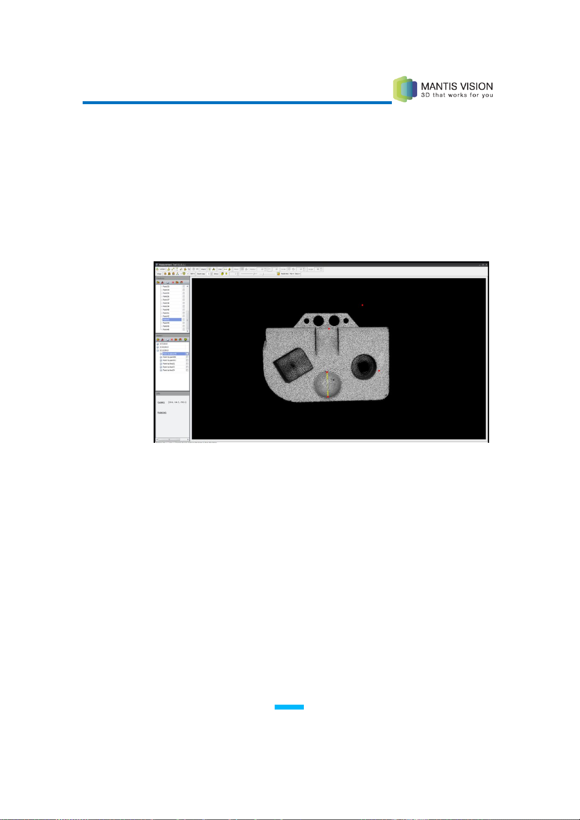
F5 3D Imaging System User Manual
99
4 Double-click a different point in the scene (line’s end point).
5 Click a different point to change the second point. Press Enter to define the
line.
– OR –
Instead of defining a new line, select a previously defined line by
double-clicking the line in the Primitives pane. The line appears in the Viewing
Area.
Figure 94: Defining the Line
6 Double-click a point.
– OR –
Instead of defining a new point, select a previously defined point by
double-clicking the point in the Primitives pane. The line appears in the
Viewing Area.
The perpendicular distance from the line appears in the selected
measurement unit.

F5 3D Imaging System User Manual
100
Figure 95: Distance from a Line to Points
7 Select additional points to display their distance from the line.
8 Press Enter. The Plane-to-point measurement is entered into the History pane
and the subparts are entered into the Primitives pane.
Measuring the Angle Between Two Lines
► To measure the angle between two lines:
1 Make sure that either the Free or Snap Plane option is selected.
2 Click the icon on the Measurement toolbar.
3 Double-click a point in the scene (vertex point).
– OR –
Instead of defining a new point, select a previously defined point in the
Primitives pane.
4 Double-click another point in the scene (first line’s end point).
– OR –
Instead of defining a new point, select a previously defined point in the
Primitives pane.
 Loading...