

Page 1

© 2006 Mantis, Div. of Schiller-Pfeiffer Inc. All Rights Reserved.
© 2006 Mantis, Division de Schiller Pfeiffer Inc. Tous droits réservés.
© 2006 Mantis, Division von Schiller Pfeiffer Inc. Alle Rechte vorbehalten.
Owners manual and safety instructions
Manuel d’utilisation et consignes de sécurité
Benutzerhandbuch und Sicherheitshinweise
Pruner E System
Élagueur E System
E-System-Astsäge
Page 2
1
Table of contents
Important information
A. Introduction
This attachment is designed for trimming light to medium size
branches.
B. Pruner attachment specification.
C. Contents of the package
1. Pruner attachment assembly with plastic gear case cover
2. Chain guide
3. Saw chain
4. Chain Guide cover
D. Service information contact
If you have questions about any topic in this manual,contact
your local authorised Mantis dealer.
WARNING DANGER
ATTENTION: THIS SYMBOL POINTS OUT
IMPORTANT SAFETY INSTRUCTIONS
WHEN YOU SEE THIS SYMBOL
HEED ITS WARNING! STAY ALERT!
WARNING DANGER
READ & UNDERSTAND THIS MANUAL BEFORE
ATTEMPTING TO OPERATE THIS MACHINE.
TO REDUCE THE POTENTIAL FOR ACCIDENTS,
COMPLY WITH THE SAFETY INSTRUCTIONS IN
THIS MANUAL. FAILURE TO COMPLY MAY RESULT
IN SERIOUS PERSONAL INJURY AND OR
EQUIPMENT AND PROPERTY DAMAGE.
Important information
Introduction . . . . . . . . . . . . . . . . . . . . . . . . . . . .1
Special safety information . . . . . . . . . . . . . . . .1
Safety and warnings
Safety labels . . . . . . . . . . . . . . . . . . . . . . . . . . .2
General safety rules . . . . . . . . . . . . . . . . . . . . .3
Assembly instructions . . . . . . . . . . . . . . . .5
Operation . . . . . . . . . . . . . . . . . . . . . . . . . .7
Maintenance . . . . . . . . . . . . . . . . . . . . . . .8
Sharpening the blade . . . . . . . . . . . . . . .10
Warranties policy . . . . . . . . . . .Back cover
E. Special safety information
MODEL SHAFT TOTAL OIL TANK
LENGTH WEIGHT VOLUME
330106 75 cm 1.8 kg
(4.1 oz)
122 ml
Page 3

2
Safety and warnings
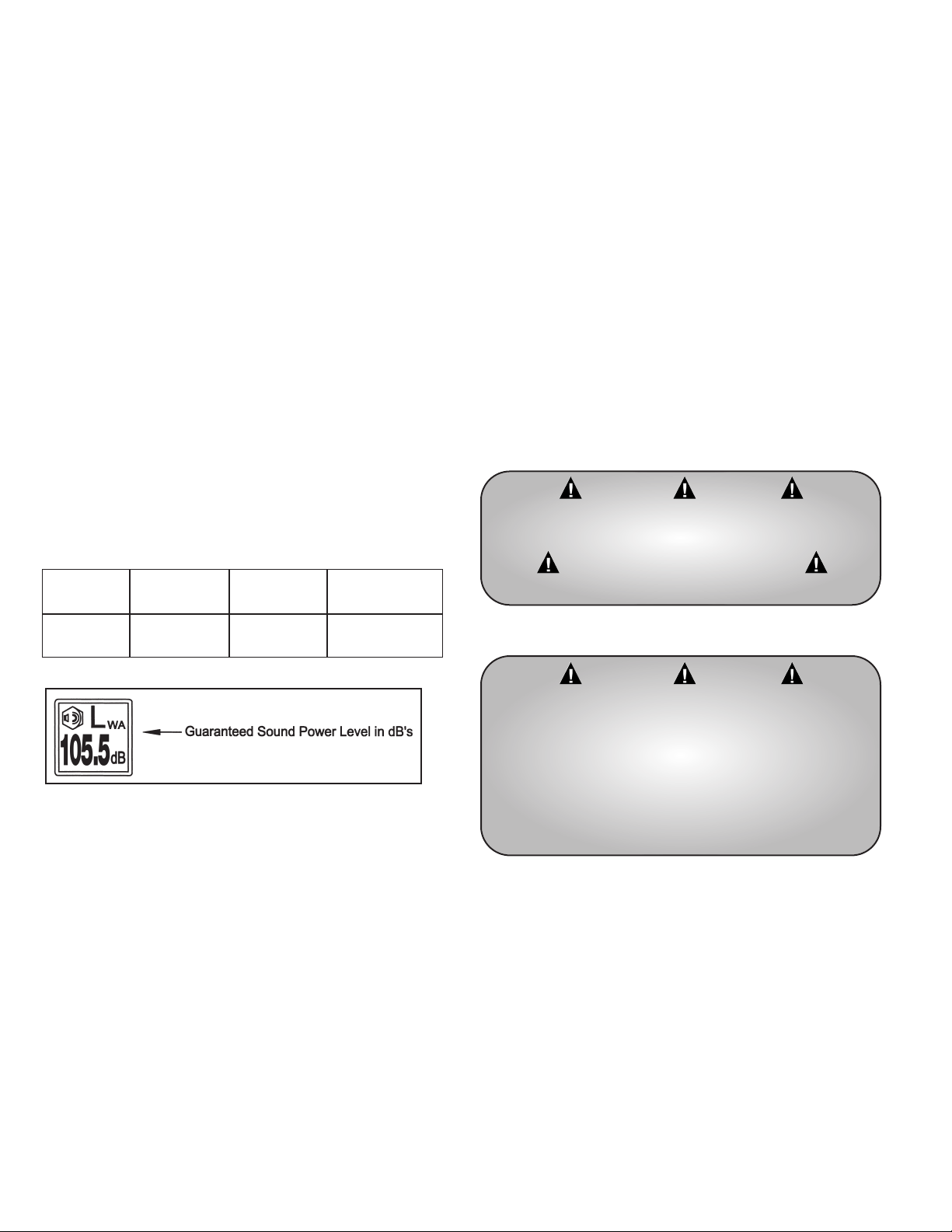
A. Safety labels
Please pay particular attention to the warning and information
labels found on various parts of this pruner attachment unit.
They are an important part of the safety system. These labels
must be replaced in time due to abrasion, etc. It is your
responsibility to replace the labels when they become hard to
read. The location of these labels and their part numbers for
ordering are shown below.
WARNING – DANGER
IMPROPER USE OR CARE OF THIS PRUNER,
OR FAILURE TO WEAR PROPER PROTECTION
CAN RESULT IN SERIOUS INJURY.
READ AND UNDERSTAND THE RULES FOR
SAFE OPERATION AND ALL INSTRUCTIONS
IN THIS MANUAL.
WEAR EYE AND HEARING PROTECTION,
HELMET AND PROPER CLOTHING.
READ AND
UNDERSTAND
OPERATOR’S MANUAL
BEFORE USING!
WARNING! WEAR
HELMET. DANGER OF
FALLING BRANCHES
WARNING! WEAR SLIP-
RESISTANT FOOTWEAR.
MAINTAIN FOOTING
AND BALANCE AT ALL
TIMES.
DO NOT STAND
ON SLIPPERY, UNEVEN
OR UNSTABLE
SURFACES. DO NOT
WORK IN ODD
POSITIONS OR ON A
LADDER. DO NOT
OVER REACH.
WARNING! DANGER
FROM OVERHEAD
ELECTRIC POWER
LINES. KEEP SAFE
DISTANCE!
KEEP BYSTANDERS AT
A SAFE DISTANCE
WARNING! WEAR EYE
AND EAR PROTECTION
WARNING!
Oilier control label
P/N 331178
P/N 331177
Page 4

3
General safety rules
1. Remove branches in sections. Maintain safe operating
positions, to avoid risk of being struck by falling branches
or by those that rebound after hitting the ground
2. Cover saw chain with guard during transport and storage.
3. Do not hit rocks, stones, tree stumps, and other foreign
objects with the working unit. If saw chain strikes an
obstruction, stop engine immediately, unplug unit and
inspect saw chain for damage.
4. Do not operate with a dull, fractured or damaged saw
chain.
WARNING
WHEN USING ELECTRIC TOOLS, BASIC SAFETY
PRECAUTIONS, INCLUDING THE FOLLOWING,
SHOULD ALWAYS BE FOLLOWED TO REDUCE
THE RISK OF FIRE, ELECTRIC SHOCK AND
PERSONAL INJURY.
Pay particular attention to all sections regarding safety.
Read and understand all these instructions before operating this
product and save these instructions. Be familiar with the
controls and the proper use of equipment.
For safe operations:
1. Keep work area clean.
Cluttered areas and benches invite injuries.
2. Consider work area environment.
Do not expose power tools to rain. Do not use power tools
in damp or wet locations. Keep work area well lit. Do not
use power tools where there is risk of fire or explosion.
3. Guar
d against electric shock.
Avoid body contact with earthed or grounded surfaces,
e.g. pipes, radiators, stoves, ovens, refrigerators.
4. K
eep children away.
Do not let visitors touch the tool or extension cord. All
visitors should be kept away from area. Local regulations
may restrict the age of the operator.
5. Store idle tools.
When not in use, tools should be stored in a dry, high or
locked up place, out of reach of children.
6. Do not force the tool.
It will do the job better and safer at the rate for which it
was intended. Walk, never run.
7. Use the right tool.
Do not force small tools or attachments to do the job of a
heavy duty tool. Do not use tools for purposes not
intended; for example, do not use chain saw attachment to
cut tree limbs or logs.
8. Dr
ess properly.
Do not wear loose clothing or jewellery that can be caught
in moving parts. Long trousers, non-slip gloves and sturdy
work shoes with non-skid soles are recommended when
working outdoors. Wear protective hair covering to contain
long hair.
9. Use protective equipment.
To avoid injury, wear ear, eye protection, face or dust mask
if the operation is dusty. To avoid injury from falling
branches, wear helmet. Eye protection must meet
applicable CE requirements.
10. Do not abuse the cord.
Never carry the tool by the cord or yank it to disconnect it
from the socket. Keep the cord away from heat, oil and
sharp edges.
11. Maintain tool with car
e.
Keep cutting tools sharp and clean for better and safer
performance. Follow instructions for lubrication and
changing accessories. Inspect tool cord periodically and if
damaged, have it repaired by an authorised service facility.
Inspect extension cords periodically and replace, if
damaged. Keep handles dry, clean and free from oil and
grease.
12. Disconnect tools.
When not in use, before servicing and when changing
accessories such as blades, bits and cutters.
13. Remove adjusting keys and spanners.
Form the habit of checking to see that keys and adjusting
spanners are removed from the tool before turning it on.
14. A
void unintentional starting
.
Do not carry a plugged in tool with a finger on the switch
trigger. Ensure switch is off when plugging in.
15. Use outdoor e
xtension leads.
When tool is used outdoors, use only extension cords
intended for outdoor use.
16. Important extension cord information:
a. Make sure the extension cords are in good condition
before use.
b. Based on the total length of cord that you are going
to use, check the chart to make sure the cord meets the
correct minimum cord gauge (AWG) requirements.
IMPORTANT NOTE:
Using an undersized cord or a larger number cord gauge
(AWG) than recommended in the chart, will cause a loss in
power and overheating of the unit. Using a smaller number
cord gauge (AWG) than recommended in the chart, is
acceptable.
Page 5
4
Extension cord chart (minimum cord gauge (AWG)
17. Stay aler
t
.
Watch what you are doing. Use common sense. Do not
operate tool when you are tired, ill or under the influence
of alcohol or other drugs.
18. Chec
k damaged par
ts.
Before further use of the tool, a guard or other part that is
damaged should be carefully checked to determine that it
will operate properly and perform its intended function.
Check for alignment of moving parts, free running of
moving parts, breakage of parts, mounting and any other
conditions that may affect its operation. A guard or other
part that is damaged should be properly repaired or
replaced by an authorised service centre unless otherwise
indicated in this instruction manual. Have defective
switches replaced by an authorised service facility. Do not
use the tool if the switch does not turn it on and off.
Don’t operate the machine with a damaged or excessively
worn cutting device.
Length (metres)
.3 to 7.8 7.9 to 15.5 15.6 to 30.6 30.7 to 45.7
Cord gauge (AWG) 18 16 14 12
WARNING – DANGER
LITTLE WONDER WILL NOT BE RESPONSIBLE
FOR THE FAILURE OF CUTTING DEVICES OR
ACCESSORIES THAT HAVE NOT BEEN TESTED
AND APPROVED FOR USE WITH THIS UNIT.
USE ONLY MANUFACTURER-RECOMMENDED
REPLACEMENT PARTS.
19. The use of any accessory or attachment, other than those
recommended in this instruction manual, may present a
risk of personal injury.
20. Have your tool repaired by a qualified person.
This electric tool conforms to relevant safety requirements.
Repairs should only be carried out by qualified persons
using original spare parts, otherwise this may result in
considerable danger to the user.
21. Keep in mind that the operator or user is responsible for
accidents or hazards occurring to other people or their
property.
22. Work only in daylight or in good artificial light.
23. Keep all guards attached at all times when unit is operated.
24. Always use the shoulder strap.
Adjust the strap for comfort before starting the engine.
25. Secur
e unit dur
ing tr
ansport to prevent damage or injury.
26. Machine should not be used in any position that causes
any part to come within 3 metres of overhead electrical
lines. Always be aware of overhead power lines.
27. Always keep a firm grip on both handles when motor is
running: one hand grasps the front “loop” handle while the
other hand grasps the rear handle. Severe injuries can
result if you try to use this machine with only one hand or
with an insecure grip.
28. Thoroughly inspect the area where equipment is to be
used and removed all objects, which can be thrown by the
machine.
29. Always keep area clear of children, pets, and bystanders.
30. Always inspect your unit before each use and ensure that
all handles, guards and fasteners are secure, operating, and
in place. Be sure that all electrical cords are not damaged
or broken.
31. Always maintain and examine your attachments with care.
Follow maintenance instructions given in manual.
32. Don’t attempt to repair any part of the extended reach
“E” system. Have repairs made by a qualified repairman.
See that only original “Mantis” parts are used.
33. Maintain a firm footing and good balance, do not
overreach while trimming. Before you start to trim, check
the work area for obstacles that might cause you to lose
your footing, balance or control of the machine. While
operating the machine always be sure of a safe and secure
operating position especially when using steps or a ladder.
Always be sure of your footing on slopes.
WARNING – DANGER
IMPROPER ASSEMBLY OF THIS EQUIPMENT
CAN RESULT IN SERIOUS INJURY. MAKE SURE
TO FOLLOW ALL INSTRUCTIONS CAREFULLY.
IF YOU HAVE ANY QUESTIONS, CONTACT YOUR
LOCAL AUTHORISED MANTIS DEALER.
34. Always disconnect power cord from power source:
a. Before cleaning blockages.
b. Before checking, cleaning or working on the
cutting portion of the unit.
c. After striking a foreign object: inspect the cutting
part for damage and make repairs before restarting
and operating the unit.
d. If machine starts to vibrate abnormally (check
immediately).
e. Whenever you leave the unit.
Page 6

5
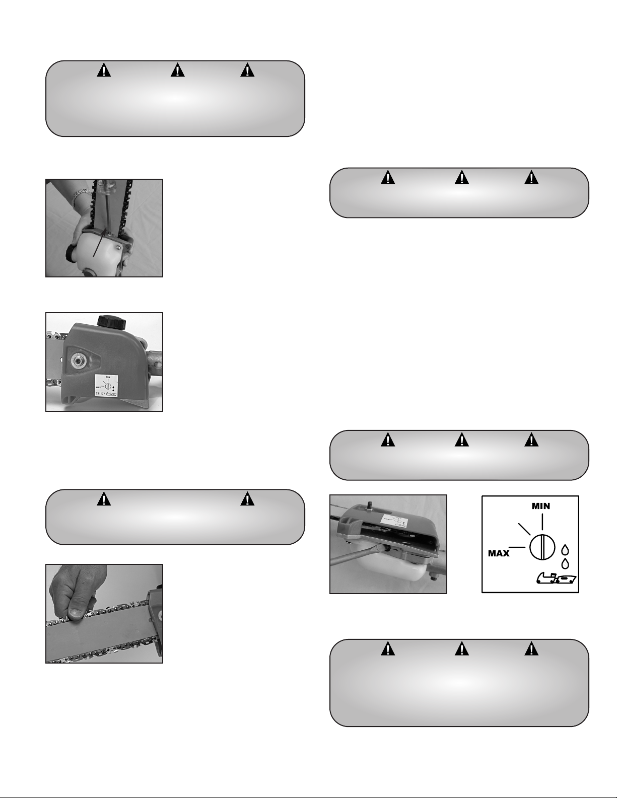
1. Unscrew the mounting nut from the gear case cover. Open
the cover. (Picture 3)
2. Mount the chain guide. Be sure that threaded pin fits into
the opening in the guide bar. (Picture 4)
3. Fit the saw chain into the groove in the chain guide bar,
and around the sprocket.
4. Be sure that pin of the chain tensioner fits into the lower
hole of the guide bar. (Picture 4)
5. Be sure the orientation of the chain is correct.
(Pictures 5 and 6)
6. Hold it in place, and put gear case cover over the threaded
pin. Attach mounting nut. Do not tighten. (Picture 7)
7. Adjust the tension of the chain and tighten the nut.
(Picture 8)
Assembling the Pruner (installing the saw chain)
With a basic understanding of kickback, you will reduce or
eliminate the element of surprise that may contribute to an
accident.
Kickback may occur when the moving saw chain at the nose of
the guide bar touches an object, or when the wood closes in
and pinches the saw chain in the cut. In some cases, this may
cause fast reverse action, kicking the unit up and back or down
and back towards the operator. The operator can lose control of
the device, and that could result in serous personal injury.
Kickback
WARNING DANGER
CHAIN HAS A VERY SHARP EDGE, HANDLE WITH
CARE. ALWAYS WEAR GLOVES; OTHERWISE
SERIOUS PERSONAL INJURY MAY RESULT!
Picture 3
Picture 7 Picture 8
WARNING DANGER
PAY ATTENTION TO THE CORRECT DIRECTION
OF THE CHAIN SAW TEETH
Keep a firm grip on the pruner handles at all time!
Picture 6
Direction of the chain movement
35. Securing the e
xtension cor
d.
Bend the extension cord about 40 cm from the plug end.
Push that bend through the oblong opening, then loop the
bend under the
cord retaining clips as
shown. This will prevent
the extension cord from
detaching from the hedge
trimmer plug.
Picture 4
Threaded pin
Opening in guide bar
Pin of
the chain
tensioner
Picture 5
Correct direction
of chain links
Page 7
6
1. Loosen mounting nut and adjust the chain tension by
turning the tensioner screw
2. Hold unit vertically, and tighten mounting nut
3. Move saw chain backwards on guide bar by hand. Saw
chain should move freely on guide bar if it is in proper
mesh with the sprocket. If saw chain is difficult to rotate or
binds on guide bar, it is too tight. Re-adjust if necessary.
Adjusting saw chain tension
1. Power pruning mechanism is equipped with the automatic
oiling system that can be adjusted in the field. The saw
chain bar, and chain are lubricated when chain rotates. The
pump is set at the factory to a minimum flow rate.
2. Remove oil fill cap and fill reservoir with a quality, low
viscosity guide bar and saw chain oil. Tighten the cap
securely.
3. After starting the motor, run the chain at medium speed
and check the saw chain. Very little visible oil on the saw
chain will provide sufficient lubrication.
4. The oil tank will provide about 40 min. of cutting time
(when set to a minimum flow rate). Refill the oil tank as
needed.
5. A temporary increase in oil flow is recommended when
cutting hardwood or wood showing a large amount of sap.
This will speed oil consumption, and require more frequent
oil tank refills.
6. To adjust oil pump to max, the control screw must be
pressed in slightly prior to turning. Failure to do so
could damage the pump or screw.
7. Wipe debris from around the oil fill cap prior to re-filling
the oil reservoir.
Lubricating the guide bar and chain
WARNING DANGER
IT IS VERY IMPORTANT TO MAINTAIN THE
PROPER CHAIN TENSION. RAPID WEAR OF THE
GUIDE BAR OR THE CHAIN COMING OFF EASILY
CAN BE CAUSED BY IMPROPER TENSION.
WARNING DANGER
NEVER FILL THE OIL TANK OR ADJUST THE OIL
FLOW WHILE MOTOR IS RUNNING.
DISCONNECT POWER CORD FROM THE
POWER SOURCE FIRST.
WARNING DANGER
THE OIL FLOW RATE ADJUSTING SCREW HAS 3
INCREMENTAL SETTINGS.
WARNING DANGER
TO PREVENT PLASTIC DETERIORATION, DO NOT
USE SYNTHETIC OR SILICONE BASED OIL.
WARNING – DANGER
BE SURE UNIT IS UNPLUGGED BEFORE
MAKING ANY ADJUSTMENTS.
Page 8

7
Check the balance of the assembled unit. The handles and
shoulder harness have been assembled at the factory and set
according to the average size person. This can be adjusted to
the operator’s preference by simple loosening the screws and
sliding handles up or down the shaft. Re-tighten the screws.
Balancing the unit
If you need to cut 7-10 cm diametre branches use the
following technique:
1. Start cutting from the bottom of the branch moving pruner
up. (Fig 1)
2. Finish the cut by starting from the top of the branch and
moving down. (Fig. 2)
How to cut thicker branches
No tools are required to attach the pruner to the power head.
1. Pull the spring pin up on the adapter of the power head
shaft assembly. (Picture 7)
2. Carefully fit pruner drive shaft into adapter, making sure
that male spline of the inner drive shaft engages into the
female spline socket of the power head shaft.
3. When the drive shaft is properly aligned, the spring pin
will drop into the hole on the shaft of the pruner
attachment. A click should be heard when completed.
4. Insure two shaft parts are fully engaged by twisting them.
Full engagement will prevent shaft rotation.
5. Secure assembly by tightening the knob. (Picture 8)
6. Unit handles can be re-adjusted to the operator’s
preference by simple loosening the screws and sliding
handles up or down the shaft.
Attaching the Pruner to the Power
Head Assembly
1. Check direction branch will fall.
2. If branch is long, remove it in several pieces.
3. Do not stand directly under the branch being cut.
4. With both hands on the handles, push lockout trigger
button with your thumb and squeeze trigger. Start cutting
when chain rotates at full RPM.
5. Proper cutting position of the pruner:
Hold the pruner against the branch as shown above. This
position will reduce branch movement.
Pruning techniques
Picture 6
Picture 7
Picture 8
branch
Lockout trigger button
Trigger
Page 9

8
Service maintenance guide
Area Maintenance procedure Frequency
Spline male/female connection of the
inner drive shaft
Lubricate 20-25 hrs
Gear case
Use a grease gun to insert lubricant
into the grease nipple of the gear case.
Use EP2 lithium grease
20-25 hrs
Guide bar
Inspect/clean/replace
The guide bar opening should be always
a square. When it’s worn, the chain tilts.
Check for wear of the guide bar opening.
Worn bar needs to be repaired or replaced.
Keep lubrication opening of the
guide bar clean from sawdust
Before each use
Remove
Lubricate
Grease nipple
Remove sawdust
from the groove
Guide bar lubrication opening
GOOD
WORN
GUIDE BAR SECTION
Page 10

9
Area Maintenance procedure Frequency
Oiling port
Inspect/clean
Before each use
Nose sprocket
Clean/lubricate Before each use
Saw chain Inspect/clean/sharpen/lubricate/replace Before each use
Screws/nuts/bolts Inspect/tighten/replace Before each use
Service maintenance guide
Oiling port
Grease port of the nose
sprocket
Area Maintenance Before Every 25 Every 50 Every 100 Note
use hours hours hours
Cutting Parts Replace if
something is wrong
Screws, nuts Tighten, replace Not adjusting
bolts screws
IMPORTANT: Time intervals shown are maximum. Actual use and your experience will determine the frequency of
required maintenance.
Page 11
10
• A Low-kickback
Chain
• Low-vibration Chain
• Narrow-kerf Chain
FILING
TOOLS FOR FILING
Saw chain sharpening procedure
Square-ground Filing
WHO SHOULD PERFORM SQUARE-GROUND FILING?
Most chain saw users will probably never need to use square
ground chain, nor learn to perform square ground filing. But in
areas where the timber is larger and the guide bars used are
longer, the performance advantages of square-ground chain can
outweigh the fact that square-ground filing is more difficult
and much less forgiving of filing errors.
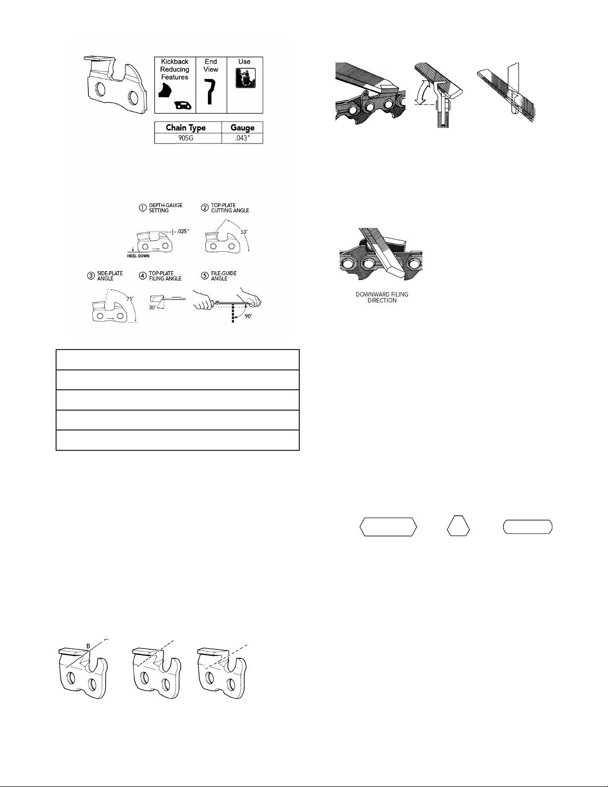
FILE POSITIONING
The file will sharpen the top plate, and the side plate,
simultaneously. This creates a line, (A), where the top plate
cutting angle meets the side-plate angle. For best results, file so
that the line joins the cutting corner (B).
CORRECTLY INCORRECT INCORRECT
FILED CORNER TOO HIGH TOO LOW
To properly sharpen the cutter, use the correct filing position,
as shown here from three different points of view:
FILE DIRECTION
The chain manufacturer
recommends that square-ground
chain be filed from the outside in
(in a downward direction). This
leaves a better edge on the
chromed cutting surfaces and
makes it easier to keep the file’s
position, and the resulting cutting
edges, in correct alignment as
shown in the preceding “File positioning” section. Filing from
the outside in will wear out your file faster, however. Some
square-ground chain users may prefer to file from the inside
out (in an upward direction). You should be aware that insideout filing is much more difficult. But whichever direction you
choose, be sure your file and your cutting edges stay
positioned as shown in the preceding “File positioning”
section. File all cutters on one side of the chain, then reverse
the chain and repeat the process. Use the same file positions
for cutters on the opposite side of the chain.
TOOLS
Only use files specially designed for square-ground chisel
cutters, available from your chain saw dealer.
DOUBLE BEVEL HEXAGON “GOOFY”
SIDE VIEW END VIEW TOP VIEW
Description
4.5 mm Round file
4.5 mm Assembled file guide
.025 inch Drop-centre depth-gauge tool
Depth-gauge file (flat)
Page 12

11
GULLET FILING
Approximately every 5th sharpening, clean out gullets
with a 7/32" round file. File gullets from the inside out (the
side opposite from sharpening). Leave a 1/8 inch (3.175 mm)
shelf behind the gullet.
The depth-gauge setting for all square-ground chisel chain is
.025 inch (0.64 mm).
1. Drain the oil tank.
2. Remove sawdust.
3. Lubricate for rust prevention
4. Use chain cover.
5. Store indoor.
Storage
Page 13

12
48
2
4
3
6
5
8
7
9
5
12
13
1
1
14
15
16
17
16
18
19
20
21
22
23
25
24
26
27
28
29
30
31
32
33
34
36
37
35
39
38
44
40
43
41
42
47
47
46
45
46
50
49
51
Pruner “E” System exploded view
13
51
24
25
39
38
7
12
8
48
5
9
2
26
14
20
49
21
23
22
6
3
4
19
18
15
16
17
16
1
5
1
50
27
28
29
30
31
35
44
32
37
36
34
33
43
47
46
41
45
46
40
42
47
Page 14

KEY # DESCRIPTION PART # QTY
1 GEAR CASE COVER 3331100 1
2 BEARING 6001-2Z 331101 1
3 GEAR CASE 331102 1
4 BEARING 627 331103 1
5 BOLT M5X12 331500 5
6 GREASE FITTING 331104 1
7 SCREW, TENSIONER 331501 1
8 CHAIN TENSIONER 331105 1
9 BOLT M6X30 331502 1
10 SHIM 331106 1
11 BOLT M5X25 331503 1
12 PLASTIC CHAIN COVER 331107 1
13 FLANGE LOCK NUT M6 331504 1
14 WORM GEAR 331108 1
15 OIL PUMP ASS’Y 331109 1
16 BOLT M4X10 331505 2
17 GASKET 331110 1
18 OIL PIPE ASS’Y 331111 1
19 OIL PIPE 331112 1
20 FILTER 331113 1
21 OIL TANK ASS’Y 331114 1
22 VALVE 331115 1
23 SCREW W/WASHER M5X12 331506 2
24 OIL CAP ASS’Y 331116 1
25 GASKET OIL CAP 331117 1
26 GEAR SHAFT 331118 1
KEY # DESCRIPTION PART # QTY
27 BEVEL, PINION 331119 1
28 BEARING 609 331120 1
29 BEARING 609-2Z 331121 1
30 SNAP RING 331122 1
31 SNAP RING 331123 1
32 CULLER 331124 1
33 SPROCKET 331125 1
34 COVER 331126 1
35 OILIER CONTROL LABEL 331177 1
36 WASHER 06 331507 1
37 BOLT M6X14 331508 1
38 GUIDE BAR 12” 331127 1
39 CHAIN 3/8”X0,042” 331128 1
40 OUTER SHAFT O24X750MM 331129 1
41 INTERNAL SHAFT 755X7MM 331130 1
42 INTERNAL SHAFT ADAPTER 331131 1
43 SPACER 331132 1
44 WARNING LABEL 331178 1
45 GRIP 331133 1
46 SCREW M3X12 331509 2
47 CLAMP 331134 2
48 GEAR CASE SUB-ASSEMBLY 331135 1
49 GEAR 331136 1
50 LOCK WASHER 331561 1
51 CHAIN SAFETY COVER 331270 1
13
Pruner “E” System parts list
Page 15

Specifications, descriptions, and illustrative material in this literature are as accurate as known at the time of publication, but are subject to change without notice.
MANTIS
1028 Street Road
Southampton , PA 18966
+ (215) 355-9700
2 YEAR LIMITED SERVICE & WARRANTY POLICY
FOR PRUNER ATTACHMENT
MANTIS extends this limited warranty against defects in material and workmanship for a period of
two years from the date of purchase, to the first retail purchaser and each subsequent owner during
the warranty period. This warranty covers all portions of the Mantis Pruner Attachment.
MANTIS will repair or replace, at its option, any part or parts of the product proven to be
defective in material or workmanship under normal usage during the warranty period. Warranty
repairs and replacements will be made without charge for parts or labor. All parts replaced under
warranty will be considered as part of the original product, and any warranty on the replaced
parts will expire coincident with the original product warranty. In the event of a defect or
malfunction, the purchaser must send the product, postage paid to:
Mantis
2800 Turnpike Dr.
Suite #1
2800 Commerce Centre
Hatboro, PA 19040
MANTIS assumes no responsibility in the event that the product was assembled or used in
noncompliance with any assembly, care, safety, or operating instructions contained in the Owner’s
Manual; was not used with reasonable care; or was misused, used for other than normal or
intended purposes. This warranty does not extend to parts affected or damaged by normal wear
and tear.
MANTIS MAKES NO EXPRESS OR IMPLIED WARRANTIES OR REPRESENTATIONS
EXCEPT THOSE CONTAINED HEREIN. THE DURATION OF ANY IMPLIED WARRANTY,
INCLUDING MERCHANTABILTY AND FITNESS FOR A PARTICULAR PURPOSE, IS
LIMITED TO THE DURATION OF THIS WRITTEN LIMITED WARRANTY. MANTIS
DISCLAIMS ALL LIABILITY FOR INDIRECT AND/OR CONSEQUENTIAL DAMAGES.
SOME
STATES DO NOT ALLOW LIMITATIONS ON
HOW LONG AN IMPLIED WARRANTY
LASTS AND/OR DO NOT ALLOW THE EXCLUSION OR LIMITATION OF INCIDENTAL OR
CONSEQUENTIAL DAMAGES, SO THAT ABOVE LIMITATIONS AND EXCLUSIONS MAY
NOT APPLY TO YOU. THIS WARRANTY GIVES YOU SPECIFIC LEGAL RIGHTS, AND YOU
MAY ALSO HAVE OTHER RIGHTS WHICH VARY FROM STATE TO STATE.
Page 16

DE Wir erklären in alleiniger Verantwortung, dass die elektrische 230-V-, 50-Hz-E-System-Astsäge mit einer installierten Nettoleistung von 0,95 kW:
FR Nous, déclarons sous notre seule responsabilité que l’élagueur électrique « E System » 230 V, 50 Hz d'une puissance installée nette de 0,95 kW :
GB We, declare on our sole responsibility that the 230V, 50Hz “E System” Electric Pruner with net installed power of 0.95kW:
NL Wij,
verklaren als enige verantwoordelijke dat de "E System" elektrische snoeikettingzaag van 230 V, 50 Hz met netto geïnstalleerd vermogen van 0,95 kW:
ES Nosotros,
declaramos por responsabilidad exclusiva que la motosierra podadora eléctrica “E System” de 230 voltios, 50 Hz con una potencia neta instalada de 0,95 kW:
IT Noi,
dichiariamo sotto la nostra unica responsabilità che la potatrice a sega elettrica “E System” da 230 V, 50 Hz con potenza netta all'installazione di 0,95 kW:
SE Vi, förklarar på eget ansvar att elektriska grenskärare “E System”, 230 V, 50 Hz, med installerad nettoeffekt på 0,95 kW:
DK Vi, erklærer under eneansvar, at den elektriske 230V, 50 HZ “E System” beskærer med nettoinstalleret effekt på 0,95 kW:
NO Vi, erklærer på eget ansvar at den elektriske 230-volts, 50 Hz “E System” besskjæreren med netto installeret effekt på 0,95 kW:
FI Me, ilmoitamme omalla yksinomaisella vastuullamme, että “E-Systemin” puutarhaleikkuri, 230 V, 50 Hz, jonka asennettu nettoteho on 0,95 kW:
DE Modell: Seriennummer(n): siehe auf dem Gerät Konstruktionsjahr: siehe auf dem Gerät
FR Modèle: Numéro(s) de série: voir sur l'appareil Année de construction: voir sur l'appareil
GB Model: 330112/ Serial number(s): see tool Year of manufacture: see tool
NL model: 330106 serienummer(s): zie op het apparaat constructiejaar: zie op het apparaat
ES Modelo: Número(s) de serie: véase en la máquina Año de fabricación: véase en la máquina
IT Modello: Numero(i) di serie: vedi la targhetta sull'apparecchio Anno di costruzione: verdi la targhetta sull'apparecchio
SE modell: serienummer: se apparat konstruktionsår: se apparat
DK model: serienummer: se apparatet konstruktionsår: se apparatet
NO model: seriennummer: se apparatet konstruksjonsår: se apparatet
FI Malli: Sarjanumero/-numerot: ks. työkalua Valmistusvuosi: ks. työkalua
DE …beschrieben in der beigelegten Dokumentation, mit den grundlegenden Gesundheits- und Sicherheitsanforderungen der Maschinenrichtlinie 98/37/EG, der Richtlinie zur
elektromagnetischen Kompatibilität 89/336/EWG und ihrer derzeit geltenden Nachträge und der Lärmschutzrichtlinie 2000/14/EG (das Konformitätsbewertungsverfahren ist
in Anhang V beschrieben) übereinstimmt.
FR ... décrite dans les documents ci-joints est conforme aux exigences essentielles de santé et de sécurité de la directive sur les machines 98/37/CE, à la directive de
compatibilité électromagnétique 89/336/CEE et amendements en vigueur et à la directive sur les niveaux sonores 2000/14/CE (La procédure d’évaluation de conformité est
incluse à l’annexe V).
GB described in the accompanying documentation conforms to the Essential Health and Safety Requirements of the Machinery Directive 98/37/EC, Electromagnetic
Compatibility Directive 89/336/EEC and current amendments, Sound Directive 2000/14/EC (conformity assessment procedure is Annex V).
NL …beschreven in de bijgevoegde documentatie voldoet aan de Essentiële gezondheids- en veiligheidsvereisten van de EG-machinerichtlijn, 98/37/EG, de EG-
elektromagnetische compatibiliteitsrichtlijn 89/336/EEG, en huidige wijzigingen daarvan, EG-geluidsrichtlijn, 2000/14/EG (conformiteitsbeoordelingsprocedure is Bijlage V).
ES …según se describe en la documentación anexa cumple con los requisitos esenciales de la Directriz 98/37/EC de Salubridad y Seguridad de la Maquinaria, Directriz
89/336/EEC de Compatibilidad Electromagnética, y sus enmiendas actualizadas, Directriz 2000/14/EC de Nivel de Ruido, (en el proceso de evaluación de su conformidad
es el anexo V).
IT ...descritta nella documentazione in dotazione, è conforme a quanto prescritto in materia di Sicurezza e Sanità dalla Direttiva sui macchinari 98/37/EC, dalla Direttiva sulla
compatibilità elettromagnetica 89/336/EEC e relativi emendamenti e dalla Direttiva sulle emissioni acustiche 2000/14/EC (la procedura di accertamento della conformità
è indicata nell’Allegato V).
SE ... som beskrivs i bifogade dokumentation överensstämmer med väsentliga hälso- och säkerhetskrav i maskindirektivet 98/37/EG, direktivet för elektromagnetisk
kompatibilitet 89/336/EEG och aktuella ändringar, ljuddirektivet 2000/14/EG (och bedömning av överensstämmelse görs enligt Bilaga V).
DK …beskrevet i den medfølgende dokumentation overholder betinget sundheds- og sikkerhedskrav i maskineridirektivet 98/37/EU, direktivet for elektromagnetisk
kompatibilitet 89/336/EEU og aktuelle ændringer, lyddirektivet 2000/14/EU (procedure for overensstemmelsesvurdering er Tillæg V).
NO ...beskrevet i vedlagte dokumentasjon, samsvarer med viktige krav til helse og sikkerhet i maskindirektiv 98/37/EU, direktiv for elektromagnetisk kompatibilitet 89/336/EEC
og gjeldende endringer, støydirektiv 2000/14/EU (vurderingsprosedyre for overensstemmelse er vedlegg V).
FI …joka on kuvattu oheisissa asiakirjoissa, täyttää koneita koskevan direktiivin 98/37/EY ja sähkömagneettista yhteensopivuutta koskevan direktiivin 89/336/ETY olennaiset
terveys- ja turvallisuusvaatimukset, mukaan lukien nykyiset muutokset, ja ulkona käytettävien laitteiden melupäästöjä koskevan direktiivin 2000/14/EY vaatimukset
(vaatimustenmukaisuuden arviointimenetelmä on liite V).
DE EG-KONFORMITÄTS-ERKLÄRUNG ES DECLARACION DE CONFORMIDAD CEE
FR DÉCLARATION DE CONFORMITÉ CE IT DICHIARAZIONE DI CONFORMITÀ CEE
GB EC DECLARATION OF CONFORMITY SE EG FÖRSÄKRAN OM ÖVERENSSTÄMMELSE
NL EG CONFORMITEITSVERKLARING DK EU OVERENSSTEMMELSESERKLÆRING
NO EU OVERENSSTEMMELSESERKLÆRING FI EY-VAATIMUSTENMUKAISUUSVAKUUTUS
MANTIS
®
Mantis
1028 Street Rd.
Southampton,
PA 18966
USA
Page 17

DE
FR
GB
NL
ES
IT
SE
DK
NO
FI
Modell
Modèle
Model
Model
Modelo
Modello
Modell
Model
Modell
Malli
330112/
330106
Schalldruckpegel
an Bedienerposition
dB (A)
Pression sonore au poste de
l’opérateur dB (A)
Sound Pressure at the
operator position dB (A)
Geluidsdruk bij de plaats van
de operator dB (A)
Presión del ruido en la
posición del operario dB (A)
Pressione acustica presso
l’operatore dB (A)
Ljudtryck vid
användarposition dB (A)
Lydtryk ved
førerposition dB (A)
Lydtrykk ved brukerposisjon dB (A)
Äänenpaine
käyttäjän asemassa dB (A)
N/A
Schalleistungspegel
(gemessen) dB (A)
Niveau sonore (mesuré)
en dB (A)
Sound Power Level
(measured) dB (A)
Geluidsvermogenniveau
(gemeten) dB (A)
Nivel de potencia del ruido
(medido) dB (A)
Livello di potenza acustica
(misurato) dB (A)
Ljudeffektnivå (mätvärde)
dB (A)
Lydeffektniveau (målt)
dB (A)
Støy fra strøm
Nivå (målt)
dB (A)
Äänitehotaso
(mitattu)
dB (A)
102.5
Schalleistungspegel
(garantiert) dB (A)
Niveau sonore (garanti)
en dB (A)
Sound Power Level
(guaranteed) dB (A)
Geluidsvermogenniveau
(gegarandeerd) dB (A)
Nivel de potencia del ruido
(garantizado) dB (A)
Livello di potenza acustica
(garantito) dB (A)
Ljudeffektnivå (garanterad)
dB (A)
Lydeffektniveau (garanteret)
dB (A)
Støy fra strøm
Nivå (garantert)
dB (A)
Äänitehotaso
(taattu)
dB (A)
105.5
Schwingungsmessungen
m/s
2
Bügelgriff Hinterer
Griff
Mesure des vibrations
en m/s
2
Poignée Poignée
annulaire arrière
Vibration measurements
m/s
2
Loop Rear
Handle Handle
Trillingmetingen m/s
2
Lus-hendel Achter-
hendel
Medición de la
vibración m/s
2
Mango Mango
semicular trasero
Misura delle
vibrazioni m/s
2
Impugnatura Impugnatura
circolare posteriore
Vibrationsmätningar
m/s
2
Öglehandtag Bakre handtag
Vibrationsmål
m/s
2
Bøjlehåndtag Bageste
håndtag
Vibrasjonsmåling
m/s
2
Håndtak Håndtak
foran bak
Tärinän mittaukset
m/s
2
Silmukkakahva
Takakahva
3.37 3.47
DE Name, Vorname: Onraet, Bob DE Stellung: Prasident
FR Nom, Prénom: Onraet, Bob FR Position: President
GB Surname, First Name: Onraet, Bob GB Position: President
NL Naam, Voornaam: Onraet, Bob NL Positie: President
ES Apellido, Nombre: Onraet, Bob ES Posición: Presidente
IT Cognome, Nome: Onraet, Bob IT Posizione: Presidente
SE Namn, Fornamn: Onraet, Bob SE Position: President
DK Navn, Fornavn: Onraet, Bob DK Stilling: Direktor
NO Navn, Fornavn: Onraet, Bob NO Stilling: President
FI Sukunimi, etunumi: Onraet, Bob FI Asema: Toimitusjohtaja
Doc REV B 7/26/06 Declaration of Conformity-331706
DE Ort. Dautm, Unterschrift GB Place, Date, Signature ES Lugar y fecha, Firma SE Ort, datum, Underskrift
FR Lieu, Date, Signature NL Plaats, Datum, Handtekening IT Luogo e date, Firma DK Sted, dato, Underskrift
NO Sted, og, Underskrift FI Paikka, Päivämäärä, Allekirjoitus
SOUTHAMPTON,
PA. USA July 26, 2006 Onraet, Bob
Page 18

P/N 331706
7/06 REV B
MANTIS
1028 Street Road
Southampton , PA 18966
+ (215) 355-9700
 Loading...