

Page 1

Tiller/Cultivator
MAN 430159
Rev. C 10-5-16
MODEL 7268
OPERATOR’S/PARTS MANUAL
Operator’s Manual and Safety Instructions for
Tiller/Cultivator
Page 2

Welcome to the World of Mantis Gardening
Here’s your new MANTIS Tiller . . . the lightweight wonder that’s Changing the
Way Americans Garden.
Unlike big tillers, your MANTIS Tiller weighs only 21 lbs. (Model 7268). So it lifts
easily, handles smoothly, tills and weeds precisely. And, unlike other small tillers,
it features serpentine tines that churn soil to ten inches deep. It creates a soft,
®
ATTENTION MANTIS PRODUCT OWNERS!
Get maintenance tips for your Mantis
product on our web site
at www.mantis.com
smooth seed bed, even in problem soil.
Once you know how to use your tiller correctly, we guarantee you’ll love it. So rst, please read this manual. It shows, step by
step, how to use your tiller safely.
IMPORTANT MESSAGE
Thank you for purchasing this Schiller Grounds Care, Inc. product. You have purchased a world class product, one of the best designed and built anywhere.
This machine comes with Operation and Safety instructions, Parts and Service instructions and Engine instructions. The useful life and good service you receive
from this machine depends to a large extent on how well you read and understand these manuals. Treat your machine properly , lubricate and adjust it as instructed,
and it will give you many years of reliable service.
Your safe use of this Schiller Grounds Care, Inc. product is one of our prime design objectives. Many safety features are built in, but we also rely on your good
sense and care to achieve accident-free operation. For best protection, study the manuals thoroughly. Learn the proper operation of all controls. Observe all
safety precautions. Follow all instructions and warnings completely. Do not remove or defeat any safety features. Make sure those who operate this machine
are as well informed and careful in its use as you are.
See a Schiller Grounds Care, Inc. dealer for any service or parts needed. Schiller Grounds Care, Inc. service ensures that you continue to receive the best
results possible from Schiller Grounds Care, Inc. products. You can trust Schiller Grounds Care, Inc. replacement parts because they are manufactured with
the same high precision and quality as the original parts.
Schiller Grounds Care, Inc. designs and builds its equipment to serve many years in a safe and productive manner. For longest life, use this machine only as
directed in the manuals, keep it in good repair and follow safety warnings and instructions. You’ll always be glad you did.
Schiller Grounds Care, Inc.
1028 Street Road
Southampton, PA 18966-4217
PHONE (800) 366-6268 • FAX (215) 956-3855
TABLE OF CONTENTS
SAFETY RULES & WARNINGS
Special Safety Information .................................................3
Safety & Warnings .............................................................3
Safety Decal Information ...................................................3
Warning Dos ......................................................................4
Warning Don’ts ..................................................................5
Engine/Fuel Warning Dos ..................................................5
Engine/Fuel Warning Don’ts ..............................................5
ASSEMBLY ............................................................................6
Lower Handle ....................................................................7
Upper Handle Assembly ....................................................8
Tines ...............................................................................8-9
Kickstand ...........................................................................9
This Operator’s / Parts Manual is part of the machine. Suppliers of both new and
second-hand machines must make sure that this manual is provided with the machine.
FUELING & STARTING
4-Cycle Fueling & Oil Only ..............................................10
4-Cycle Corrective Action ................................................10
4-Cycle Starting Only .......................................................10
OPERATION ....................................................................11-12
TRANSPORTATION .............................................................13
STORAGE ............................................................................13
MAINTENANCE ..............................................................14-16
TROUBLESHOOTING .........................................................17
MANTIS TILLER ASSEMBLY & PARTS LIST .................18-19
LIMITED WARRANTY INFORMATION ................BACK PAGE
2 Operator’s Manual
Page 3
Safety Rules & Warnings
You will notice throughout this Operator’s Manual Safety Rules and Important Notes. Make sure you understand and obey these
warnings for your own protection.
I. SPECIAL SAFETY INFORMATION
Attention: This symbol points out our
important safety instructions.
When you see this symbol,
heed it’s warning!! Stay alert!!
To reduce the potential for accidents, comply
with the safety instructions in this manual.
Failure to comply may result in serious
personal injury, and/or equipment
and property damage.
II. SAFETY & WARNINGS
Improper use or care of this tiller or failure to wear
proper protection can result in serious injury.
Read and understand the rules for safe
operation and all instructions in this manual.
Wear hearing and eye protection.
The engine exhaust from this product contains
chemicals known to the State of California to cause
cancer, birth defects or other reproductive harm.
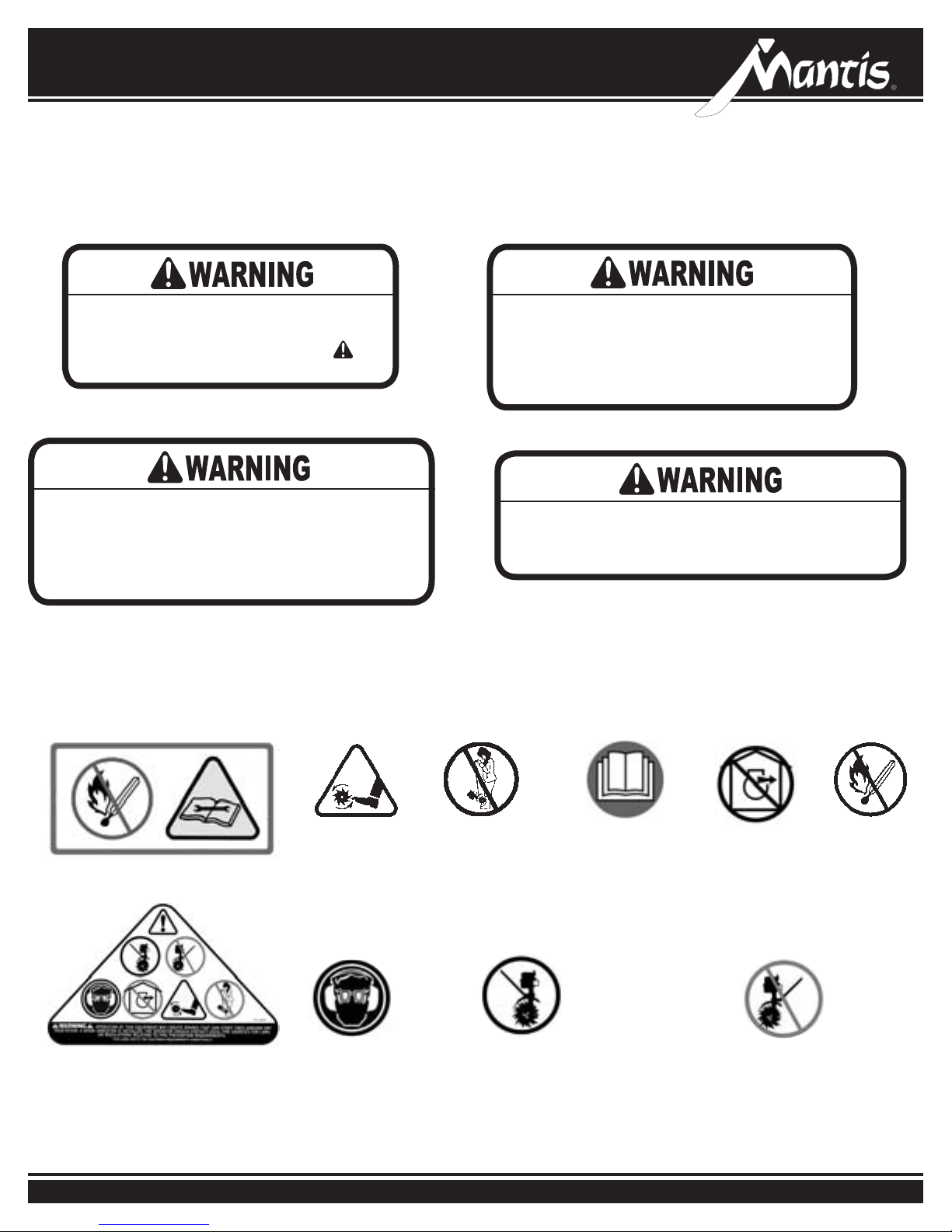
III. SAFETY DECAL INFORMATION
An important part of the safety system incorporated in this tiller are the warning and information decals found on various parts of
the tiller. These decals must be replaced in time due to abrasion, etc. It is your responsibility to replace these decals when they
become hard to read.
Cutting hazard; keep
feet and hands away
P/N 430057
P/N 400631
from rotating tines.
Do not carry the
tiller in this position.
Wear ear
and eye
Protection.
Read owner’s manual before
using tiller, or performing any
repair or maintenance. Keep
owners manual in a safe place.
Caution: when assembling
the handles, make sure
fuel tank faces away from
operator. This is the rear of
the tiller, refer to assembly
instruction on page 8-9.
Don’t operate
indoors
Don’t fuel, refuel,
or check fuel while
smoking, or near an
open ame or other
ignition source.
Incorrect assembly.
3Contact us at www.mantis.com
Page 4

If the tiller is used improperly or safety precautions
are not followed, the users risk serious injury
to themselves and others.
Read and understand this manual before
attempting to operate this tiller.
IV. WARNINGS - DOS
Read and understand the owner’s manual.
Pay particular attention to all sections
regarding safety.
1. Always keep a rm grip on both handles
while the tines are moving and/or the
engine is running. BE AWARE!! The
tines may coast after throttle trigger is
released. Make sure tines have come to
a complete stop and engine is off before
letting go of the tiller.
2. Always maintain a rm footing and
good balance. Do not overreach while
operating the tiller. Before you start to
use the tiller check the work area for
obstacles that might cause you to lose
your footing, balance or control of the
machine.
3. Thoroughly inspect the area where
equipment is to be used and remove
all objects, which can be thrown by the
machine.
4. Always keep area clear of children,
pets, and bystanders.
5. Always stay alert. Watch what you are
doing and use common sense. Do not
operate unit when fatigued.
6. Always dress properly. Do not wear
loose clothing or jewelry, they might
get caught in moving parts. Use sturdy
gloves. Gloves reduce the transmission
of vibration to your hands. Prolonged
exposure to vibration can cause
numbness and other ailments.
7. While working, always wear substantial
footwear and long trousers. Do not
operate the equipment when barefoot or
wearing open sandals.
8. Always wear ear and eye protection.
Eye protection must meet applicable CE
requirements. To avoid hearing damage,
we recommend hearing protection be
worn whenever using the equipment.
9. To reduce re hazard, keep the
engine, and petrol/gas storage area free
of vegetative material and excessive
grease.
10. Start the engine carefully, according to
the manufacturer’s instructions and with
feet well away from tool(s).
Keep all nuts, bolts and screws tight
11.
to be sure the equipment is in safe
working condition.
Use extreme caution when reversing
12.
or pulling the machine towards you.
13. Work only in daylight or good
articial light.
Operation of this equipment may create sparks
that can start res around dry vegetation. A spark
arrestor is installed. The operator should contact
local re agencies for laws or regulations relating
to re prevention requirements.
14. Always be sure of your footing on
slopes.
15. Exercise extreme caution when
changing direction on slopes.
16. Always keep a safe distance between
two or more people when working
together.
17. Always inspect your unit before each
use. Keep all knobs, nuts, bolts and
screws tight to be sure the equipment is
in safe working condition.
18. Always visually inspect to see that
the tools are not worn or damaged.
Before using your tiller, replace worn or
damaged elements and bolts in sets to
preserve balance.
19. Always maintain and examine your
Tiller with care. Follow maintenance
instructions given in manual.
20. Always store tiller in a sheltered area
(a dry place), not accessible to children.
The tiller as well as fuel should not be
stored in a house.
21. Always keep in mind that the operator
or user is responsible for accidents or
hazards occurring to other people or
their property.
4 Operator’s Manual
Page 5

V. WARNINGS - DON’TS
Don’t use tiller with one hand. Keep
both hands on handles with ngers and
thumbs encircling the handles, while
tines are moving, and engine
is running.
Don’t run with the machine, walk.
Don’t work on excessively steep slopes.
Don’t attempt to clear tines while they
are moving. Never try to remove jammed
Handle fuel with care, it is highly ammable. Fueling a hot engine or near an ignition source can
cause a re and result in serious personal injury and/or property damage.
material before switching the engine off
and making sure the tines have stopped
completely.
Don’t allow children or people unfamiliar
with these instructions to use the
machine. Local regulations can restrict
the age of operator.
Don’t let others operate tiller without
proper training.
VI. ENGINE/FUEL WARNINGS - DOS
Always use fresh gasoline. Stale gasoline
can cause damage.
Always store fuel in containers
specically designed for this purpose.
Always add fuel before starting
the engine.
Always replace all fuel tank and
container caps securely.
Always pull starter cord slowly until
resistance is felt to avoid kickback and
prevent arm or hand injury.
Always operate engine with spark
arrestor installed and operating properly.
Safety Rules & Warnings
Don’t operate while under the inuence
of alcohol or drugs.
Don’t attempt to repair this tiller. Have
repairs made by a qualied dealer or
repairman. See that only original Mantis
parts are used.
Don’t overreach. Keep a good footing at
all times.
Don’t stand in front of tiller when tines
are rotating.
Stop the engine whenever you leave
the machine and before refueling. Allow
the engine to cool before storing in any
enclosure. Replace worn or damaged
parts for safety.
If the fuel tank needs to be drained, this
should be done outdoors.
VII. ENGINE/FUEL WARNINGS - DON’TS
Never pick up or carry a machine while
the engine is running.
Don’t fuel, refuel or check fuel while
smoking, or near an open ame or other
ignition source. Stop engine and be sure
it is cool before refueling.
Don’t leave the engine running while the
tiller is unattended. Stop the engine when
carrying out maintenance and cleaning
operations, when changing tools and
when being transported by means other
than under its own power.
Never remove the cap of the fuel tank or
add fuel while the engine is running or
when the engine is hot.
Don’t refuel, start or run this tiller indoors
or in an improperly ventilated area.
Don’t run engine when electrical system
causes spark outside the cylinder. During
periodical checks of the spark plug, keep
plug a safe distance from cylinder to
avoid burning of evaporated fuel from
cylinder.
Don’t check for spark with spark plug
or plug wire removed. Use an approved
tester.
Don’t crank engine with spark plug
removed unless spark plug wire is
disconnected. Sparks can ignite fumes.
Don’t run engine when the odor of gasoline
is present or other explosive conditions exist.
Do not attempt to start the engine if
fuel is spilled, but move the machine
away from the area of spillage and avoid
creating any source of ignition until fuel
vapors have dissipated.
Don’t operate your tiller if there is an
accumulation of debris around the
mufer, and cooling ns. To reduce the
re hazard, keep the engine and fuel
storage area free of vegetative material
and excessive grease.
Don’t touch hot mufers, cylinders
or cooling ns as contact may cause
serious burns.
Don’t change the engine governor
setting or over speed the engine.
Don’t attempt to remove spark plug while
engine is hot. Removing a spark plug
from a hot engine can cause irreparable
damage to the engine and will void your
warranty.
Don’t use starter uids as they will cause
permanent engine damage.
5Contact us at www.mantis.com
Page 6

Assembly
Picture of Model 7268
T9
T21
T20
T46
T12
T1
T39
T3
T42
T40
T41
T11
T4
T7
T15
T14
WHAT COMES IN THE BOX
Key Qty. Part No. Description
T1 1 Upper Handle Throttle Side Assembly
T2 1 Upper Handle Assembly, Left
T3 2 Lower Handles W/Plug
T4 1 Handle Brace Assembly
T10 1 Plastic Carrying Handle
T21, T20,
T46
T39/T40 1 Pair Tiller/Cultivator Tines
T7 2 Handle Clamps
T9 1 Throttle Clip
T11 2 Bolts (3” long)
T12 2 Knobs
T14 4 Lock Nuts
T15 2 Cap Screws
T41 2 Tine Retaining Pins
T42 2 Carriage Bolts
Not
Shown
1 Engine Assembly (includes Fender Guard &
Worm Gear Transmission)
1 Bag of Hardware
1 4-Cycle Oil
T2
T10
Improper assembly of this tiller can result in serious injury. Make
sure to follow all instructions carefully. If you have any questions,
contact our factory at 1-800-366-6268 or an authorized Mantis dealer.
Bag Contents
T12
T9
T7
T42
T15
T41
T11
T14
WHAT YOU WILL NEED
TO ASSEMBLE THE TILLER
Prior to removing the contents and assembling, it is
important to:
• Have a clean work area.
• Make sure all necessary tools are handy.
• You will need two 7/16” wrenches. (Power tools may
be required)
6 Operator’s Manual
Page 7
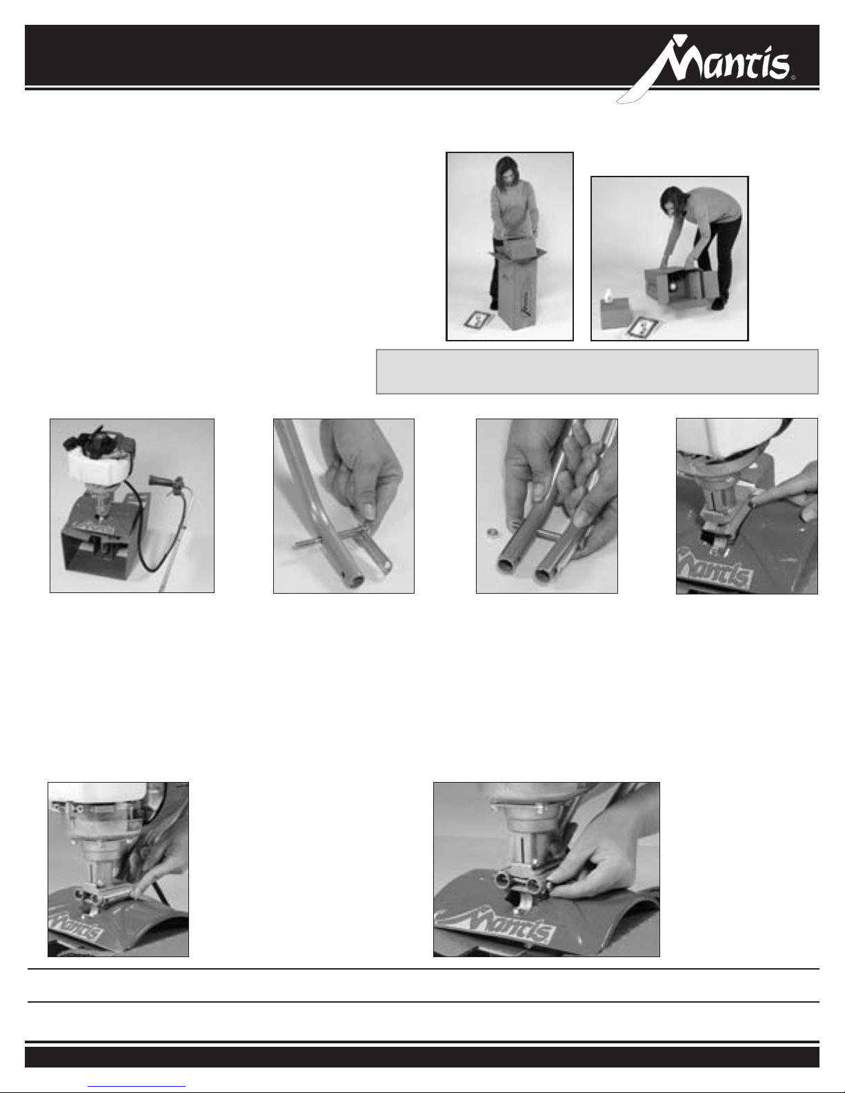
LET’S BEGIN
• With the box upright, open the box and remove the
tine box and the loose parts that are at the top of the
tiller box. Do not remove any other parts in the box.
• Lay the box on one side and open the bottom aps.
• Return the box to an upright position (as shown) and
pull the box straight up.
• Leave the engine and throttle handle in the cradle to
assist in the assembly.
• Lay everything out so you can easily identify the
parts (see parts image and list on page 6).
LOWER HANDLE ASSEMBL Y
To identify part numbers see page 6.
Assembly
NOTE: Some of the photos in this manual do not represent your
tiller engine. They are for assembly purposes only.
1
• For ease of assembly and
stability it is important that you
keep the engine assembly in its
cardboard cradle.
5
2
• Lay the handle parts within easy
reach. You’ll need one of the
handle clamps (T7) and one of
the lower handles (T3). Note that
the lower handles have a short
leg on one end.
• Fit the handle clamp along the
outside of the short leg. Line
up the holes on the clamp and
the leg.
• Take the lower handles that
you’ve just put together.
Slide them into the two
recessed channels.
• Make sure you insert them
from the rear of the tiller
(gasoline tank faces away
from the operator)... so
that the bolt ts along the
back of the housing.
6
3
• Choose one of the two 3-inch
bolts (T11). Slide it through the
rst set of holes — near the
elbow where the lower handle
curves. (Pictures 2 & 3)
• Now slide the other lower
handle onto the 3-inch bolt. Fit
the other
handle’s short leg. Add a lock
nut (T14) and tighten nger tight.
(Picture 3)
clamp onto the other
4
• Locate recessed channels
below the engine.
• Slide the second 3-inch
bolt (T11)through the
second set of holes in
the short legs. Add a
nut (T14)
nger tight until you’ve
completed assembly.
and tighten
lock
NOTE: THE LOCK NUTS ARE STAMPED. FINGER TIGHT IS APPROXIMATELY 1/2 TO 1-1/2 TURNS UNTIL YOU’VE COMPLETED ASSEMBLY.
7Contact us at www.mantis.com
Page 8
Assembly (Continued)
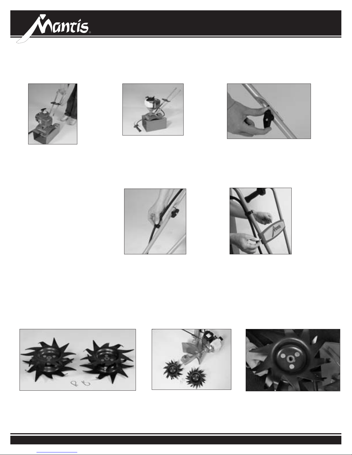
UPPER HANDLE ASSEMBLY
7a
• Lightly squeeze the lower
handles (T3) toward one another
so that they line up with the two
smaller holes on the carrying
handle (T10). Then slide the
carrying handle over and down
the lower handles. It will rest
about four to six inches above the
fender.
• Gently pull the lower handles out
to their original position.
7b
• Your Mantis Tiller will look like
this when the lower handle
assembly is complete.
9
8
• Lift the upper handle until it lines up
with the lower handle.
•
Insert carriage bold (T42) from outside in.
• Screw on knob (T12) and fully tighten
the knob at the pivot point.
10
• Follow the same steps to install the
other upper handle onto the other
lower handle.
• Use the clip (T9) to secure the throttle
cable and wire in place on the lower
handle.
TINE ASSEMBLY
• Now install the handle brace. Line it up with
the holes on the upper handles. Then insert a
cap screw (T15) and a lock nut (T14) on either
side.
• Use a wrench to tighten cap screws and lock
nuts.
• Now use wrench to tighten all nuts and bolts
rmly and securely. (Power tools may be
required)
1 2 3
• You’ll need the 2 Tines and the
2 retaining pins.
8 Operator’s Manual
• Remove the unit from the
cardboard cradle and lay the
unit on its side.
• You will notice that one side of the
Tine has a circular hole while the
other has a “D” shaped hole.
Page 9
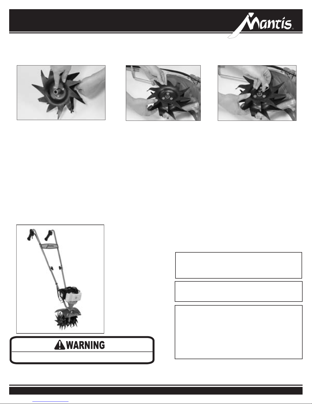
TINE ASSEMBLY (Continued)
Assembly (Continued)
4 5
• Attach the Tine so that the circular hole
slides onto the axle rst.
• When the axle protrudes from the
other side it will line up perfectly
with the “D” shaped hole.
6
• Slide a retaining pin (T41) through
the hole in the axle to secure the
Tine.
• Repeat steps for the other side.
7268
Improper Throttle installation can cause tines to rotate unexpectedly.
IMPORTANT NOTE:
Make sure you have installed the handles properly.
When you stand behind your tiller, holding the handles,
the fender warning label should face you.
IMPORTANT NOTE:
Before you use your MANTIS Tiller, read the
Safety Rules & Warnings on pages 3-5
IMPORTANT NOTE:
Be sure you have proper throttle movements and that
the throttle cable is not wrapped or twisted around the
handle bar. Hold the lockout button, fully squeeze the
throttle trigger and let go. The throttle triangle must
click in both directions. If there is any doubt, remove
air lter and visually check that the throttle triangle hits
both the idle screw and the full open stop. THIS MUST
BE DONE BEFORE STARTING THE ENGINE.
9Contact us at www.mantis.com
Page 10
4-Cycle Tiller Fueling & Starting
4-CYCLE TILLER FUELING AND OIL ONLY
IMPORTANT!
It is normal for your 4 stroke engine to smoke for the rst
minute or two of operation, however it is not necessary
for this to occur every time. This is a result of the oil being
pulled through the engine for lubrication.
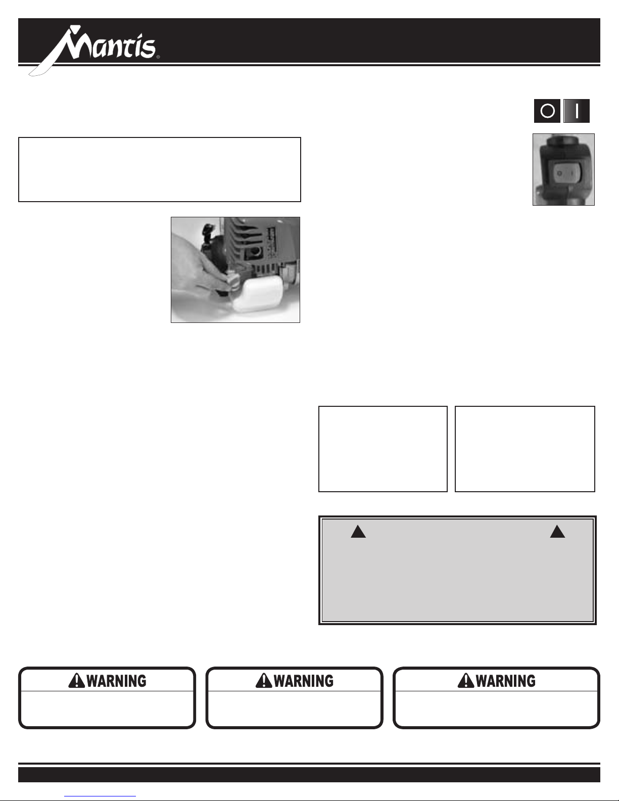
• Rock the tiller forward so that it
rests on the fuel tank.
• It is important to position the
Mantis 4-Cycle Tiller as shown in
Figure 1 so the oil will properly
ll the crankcase. Failure to do so
will cause engine damage.
• Remove the oil plug.
• Pour in 2.7 . oz. of approved,
4-cycle engine oil.
• Always check the oil level before each use. The oil level should
reach the inner rst thread of the reservoir. Do not overll.
• Replace the oil plug.
• Then return the unit to the upright position and put the kickstand
down.
Fueling your Mantis 4-Cycle Tiller/Cultivator is easy. Unscrew the gas
cap and ll the tank about four-fths of the way up with 89 octane
unleaded gasoline. And remember, always drain the gas when
transporting the unit from one location to another.
Figure 1
4-CYCLE TILLER STARTING ONLY
Starting the engine for the rst time, or “cold
starting”, is easy.
• First, make sure the start/stop switch, located on
the throttle handle, is in the start position, which
is indicated by the “I” symbol.
• Close the choke by moving the choke lever to the
up position.
• Press the primer bulb approximately 6 times until he bulb is lled
with gas. Once it is lled, press it two more times.
• Pull the starter cord lightly until you feel resistance and then give it
a short, brisk pull. Your tiller should start immediately. Do not pull
the cord all the way out and do not let it snap back into the starter
housing.
•
Once it is running, open the choke. Ensure the lever is fully down
• To stop the engine, simply push the start/stop switch to the
stop position “O.”
• To start a warm engine, follow the same procedure. Except now you
can leave the choke lever in the down position and there is no need
to pump the primer bulb.
• Before using the tiller, let the engine run for a minute to warm up.
And before shutting it down, let the engine run briey to
cool down.
IMPORTANT NOTE:
Check the oil level in the
engine before each use. If
oil is low see your 4 Stroke
Tiller Engine Manual and
information above for
details.
Never use starting uids as
they will cause permanent
engine damage. Using them
will void the warranty. Before
you use the tiller, read the
Safety & Warning rules on
pages 3-5.
OFF ON
Switch
OR ANY FUELS NOT MEETING HONDA REQUIREMENTS ARE NOT APPROVED
FOR USE IN GASOLINE ENGINES. USE OF ALTERNATIVE FUELS MAY CAUSE
PERFORMANCE PROBLEMS, LOSS OF POWER, OVERHEATING, FUEL VAPOR
LOCK AND UNINTENDED MACHINE OPERATION, INCLUDING, BUT NOT LIMITED
TO, IMPROPER CLUTCH ENGAGEMENT. ALTERNATIVE FUELS MAY ALSO CAUSE
PREMATURE DETERIORATION OF FUEL LINES, GASKETS, CARBURETORS AND
OTHER ENGINE COMPONENTS.
Do not operate the engine in a conned
space where dangerous carbon monoxide
fumes can collect.
Fuel is extremely ammable. Handle it with
care. Keep away from ignition sources. Do not
smoke while fueling your equipment
10 Operator’s Manual
! !
WARNING • DANGER
ALTERNATIVE FUELS, SUCH AS E-15 (20% ETHANOL), E-85 (85% ETHANOL)
Do not squeeze the throttle trigger when starting. Main-
Avoid accidental blade engagement.
tain proper idle speed adjustment (2500-3100 rpm)
Page 11
4-Cycle Tiller Operation
If engine does not stop when switch is put in the stop
position, release the throttle, allow engine to idle. Put
the tiller down, and slide the choke lever to the cold start
(closed) position. Have product serviced before using.
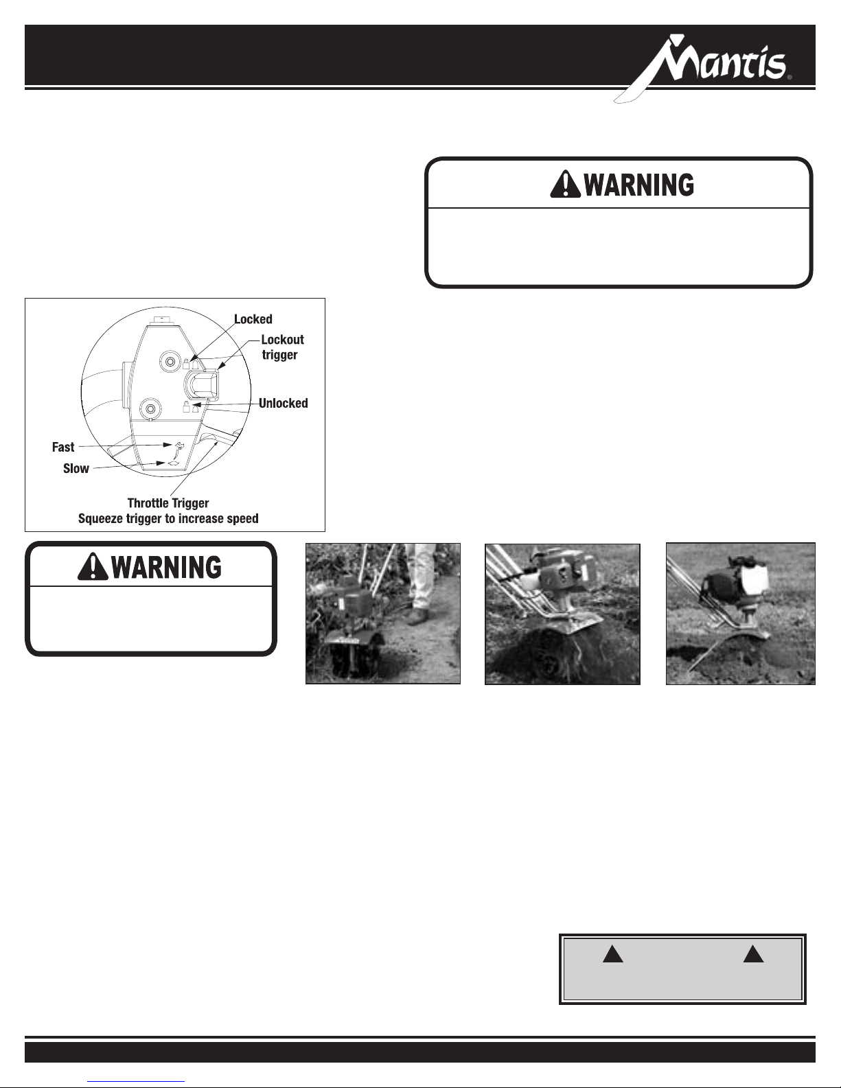
Figure 1
Read the instructions carefully. Be
familiar with the controls and the
proper use of the equipment.
NOW YOU’RE READY TO USE
YOUR MANTIS TILLER.
If you’ve seen other tillers, your MANTIS
Tiller may surprise you. It tills best when
you pull it backward! You see, when you pull
your MANTIS Tiller backward, you give extra
resistance to the tines, so they dig deeper.
(Figure 2)
In addition, when you go backward, you erase
your footprints. So your soil stays light and
uffy. With other tillers, by contrast, you walk
right over the soil you’ve just tilled, packing it
down, so it’s less plantable.
RUN YOUR MANTIS TILLER
LIKE A VACUUM CLEANER
Place your Tiller at the head of the row or
area you want to till. Start it up. Then use
an easy rocking motion. First, pull your Tiller
backward. Then use an easy rocking motion.
Again, pull your Tiller backward. Then, let
A SPECIAL FEATURE
(With the idle set properly and the engine
running)
Even when the engine is running, the
tines won’t turn unless you squeeze the
throttle trigger on the handlebars. When
you release the throttle trigger, the tines
will stop
.
A TIP FOR EXTENDING
YOUR ENGINE’S LIFE
After you start the engine, let your tiller
warm up for two to three minutes before
you use it. Then, before you put your
Figure 2 Figure 3 Figure 4
it move forward just a little bit. Then pull it
backward again. This will help you till deeper.
Keep repeating these steps until you’ve tilled
an entire row. Start again on the next row. It’s
much like running a vacuum cleaner! (Figure 3)
You Can Even Control Depth.
For Deeper Tilling:
Move your Tiller slowly back and forth, as you
would a vacuum cleaner. Work the same area
over and over until you’ve dug to your desired
depth. (Figure 4)
For Shallow Tilling:
Switch the tines to the cultivating position.
(See page 12 to learn how.) Then move your
Tiller quickly over your soil surface.
tiller away, let it idle for a minute to give
the engine a chance to cool down.
OPERATION
With engine running, and both hands
on the handles, hold down the throttle
lockout trigger (Figure 1), then squeeze
the throttle trigger gradually to increase
the engine speed and engage the tines.
NOTE: This step must be repeated each
time your tiller trigger is released.
For Big Weeds or Tough Roots:
Let your Tiller rock back and forth over the
tough spot, until the tines slice through the
weed or root.
Your MANTIS Tiller Handles Special Tilling
Projects:
Want to turn part of your lawn into a colorful
ower border? Your MANTIS Tiller makes it
easy! Just run your Tiller back and forth until
the sod begins to break up. Then continue
tilling. Your Tiller will chop the clumps of sod
until they’re ne. Then, it will work them into
the soil. Pretty soon, you’ll have a soft, fresh
planting bed.
WARNING
! !
ALWAYS MAKE SURE THE HANDLE KNOBS ARE
SECURE BEFORE STARTING YOUR MANTIS TILLER.
11Contact us at www.mantis.com
Page 12
4-Cycle Tiller Operation (Continued)
If your tines get jammed or entangled, shut off the
engine at once. Remove the obstruction while the
engine is off. Never try to remove an obstruction while
the engine is running. Serious injury can result.
YOUR MANTIS TILLER MAKES
WEEDING A PLEASURE!
As a tiller, your MANTIS Tiller works the soil
down to 10” (25.4 cm) deep. But, as a cultivator,
it gently cultivates the surface, only 2” to 3” (5.09
cm to 7.62 cm) deep.
First, you must switch the tines to the weeding,
cultivating position. This takes less than a
minute.
Then, your MANTIS Tiller’s sharp “tine teeth” will
slice up those pesky weeds, burying them as you
go along. And, since the tines in this position
won’t dig too deep, they won’t hurt your plants’
precious root systems.
Tilling Cultivating
The operator of this tiller is responsible for
accidents or hazards occurring to himself, oth-
er people or their property.
The result? Your Tiller will cut your weeding time
in half, and turn a tiresome chore into a pleasure.
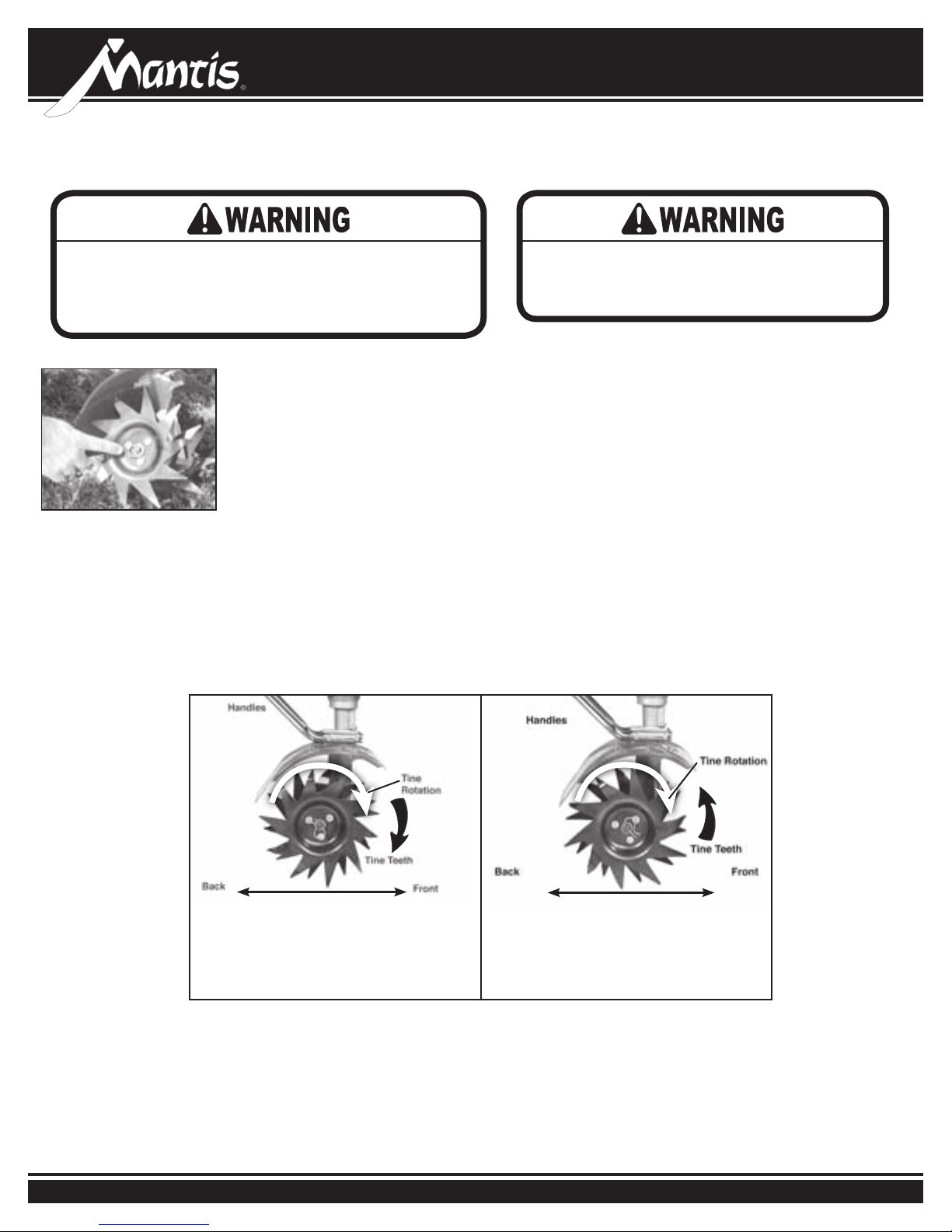
HOW TO SWITCH FROM TILLING TO
CULTIVATING POSITION
1. Make sure your Tiller is off.
2. Remove the retaining pins from the tines.
3. Remove the tines from the axle.
4. Place the right-side tine onto the left-side axle.
Place the left side tine onto the right-side axle.
The “D” hole should be to the outside.
5. Reinsert the pins. (Figure 1)
To set them for tilling, attach the tines
so the points of the blades face forward
- away from the operator. The tines’
points will contact the ground rst.
Figure 1
For cultivating, reverse the tines
so that the points of the tines face
backward - toward the operator. Now
the long at part of the tine’s blade
will contact the ground rst.
12 Operator’s Manual
Page 13

4-CYCLE TILLER TRANSPORTATION
Transporting your Tiller is easy. It’s light enough and easy to carry
using the carrying handle as seen in Figure 1.
Or, with it running, you can walk it by gently squeezing the
throttle until it moves at a comfortable pace.
Your tiller is easily transported in the back of a car or truck. Be
sure to empty the fuel tank (This is crucial)! Then stow your tiller
in the trunk of your car or truck.
Figure 1
TILLER STORAGE
Never store the equipment
with fuel in the tank or in
an area where fumes may
accumulate and breach an
open ame or spark
Each fall, or before you store your
Mantis Tiller for any long period, be sure
to take these measures:
1. Do not store your Tiller with fuel still in
it. Even under ideal conditions, stored
fuel containing ethanol or MTBE can
start to go stale in 30 days. And, since
stale fuel has a high gum content, it
can clog the carburetor, this, in turn,
will restrict fuel ow. Therefore, when
you’re ready to store your Tiller, or will
not be using it for more than 2 weeks,
drain the fuel tank completely.
2. Next, restart the engine to make
sure no fuel is left in the carburetor.
Then, run the engine until it stops.
This will prevent gum deposits,
forming inside of the carburetor and
possible engine damage.
3. Disconnect spark plug wire and
remove the spark plug. Slowly pull the
starter cord once.
4. Inspect the spark plug, and if
necessary, clean it. If you need to
replace it, buy a NGK-CMR5H.
4-Cycle Tiller Transportation & Storage
5. Install the spark plug, but leave the
spark plug wire disconnected.
6. Wipe the tines with oil or spray them
with WD-40, to prevent rusting.
7. Clean or replace the air lter.
8. Check or replace fuel lter.
9. Check the grease level in the worm
gear housing. Add grease if needed.
10. Store your Tiller in an upright position
in a clean, dry place. You can store
with the handles in an extended
position or folded down.
To fold the handles down, simply
loosen the lower 2-pronged knobs
until you can pivot the upper handles
down. (Figure 3)
Or it can be hung using the handle
brace.
11. Do you have fuel left over from last
season? Dispose of it properly. Buy
fresh oil and gasoline next season.
12. Remove Tilling Tines or attachments
and lightly oil tine shaft at least once
a year.
Figure 2
WARNING
! !
NEVER CARRY YOUR TILLER AS THE PERSON IN
FIGURE 2 IS DOING. IF YOU DO, YOU WILL SUFFER
SERIOUS INJURY.
Figure 3
IMPORTANT:
It is important to store your 4-Cycle
Mantis Tiller in an upright position.
Laying the Tiller on its side will
cause the oil to leak out of the engine
through the air cleaner case.
IMPORTANT:
Avoid any orientation that places the
top cover (engine head) down -this
may allow oil from the crankcase to
enter the combustion chamber and
cause hard starting or a locked piston.
13Contact us at www.mantis.com
Page 14

4-Cycle Tiller Maintenance
Your 4 Cycle Tiller will require some basic maintenance
to keep it performing year after year.
If you are storing your tiller for the season or longer than
30 days it is very important to empty the fuel tank to
prevent engine damage.
Undoubtedly, you will be putting your tiller through
rigorous use.
Check engine oil level, air lter and fuel lter.
Refer to your Honda® engine manual for more details.
4-CYCLE CORRECTIVE ACTION
If you suspect the engine is overlled the following procedure should
remove the excess oil from the crankcase and valve cover.
If the engine is overlled, oil will enter the crankcase and it does not
simply pour out of the oil ll opening. The excessive oil has to be
pumped out as the engine runs. Checking the oil level and draining any
excess between multiple 30 second running intervals will bring the oil
back to the proper level.
1. Place the engine on a level surface resting at on the fuel tank and
remove the oil ll cap/dipstick. Use a catch basin for any oil that
overows from the oil ll opening.
2. Replace the oil ll cap/dipstick and run the engine for approximately
30 seconds then repeat step one. Continue steps 1 & 2 until oil no
longer overows when the oil ll cap/dipstick is removed.
3. Once the oil level is corrected the engine may continue to smoke
while running for several minutes while the residual oil burns off.
Air Filter
4-CYCLE PROPER OIL FILL/
LEVEL CHECK POSITION
This position does
not allow for a
proper oil level
reading and may
cause overlling.
Engine must be resting on a at surface on the
fuel tank
Dipstick
Fuel Filter
14 Operator’s Manual
Page 15

4-Cycle Tiller Maintenance (Continued)
AIR FILTER MAINTENANCE
A wet or dirty air lter can affect the way your engine starts, performs, and wears.
So, it’s a good idea to check your air lter once a month.
If you work in dusty soil, or if you want to be on the safe side — check your lter
more often (for instance, before each use). But be sure to replace it at least once a
year, in the spring or fall.
How to Check, Clean and Change the Air Filter
IMPORTANT:
Make sure the lter is “seated”
properly in the cover. The lter
must t snugly inside the open-
ing that holds the lter in place.
Installing the lter incorrectly will
cause engine damage and void
the warranty. Fit the cover back
over the air cleaner and snap the
two locking tabs
Figure 1 Figure 2
1. The air lter is held in the air cleaner in a black housing on the side of the tiller,
behind the gas tank cap.
2. Squeeze the two locking tabs at the rear of the air cleaner cover (Figure 1) and
swing the cover towards the front of the engine to open it
3. The air lter is the dark sponge like material on the inside of the air cleaner.
Check whether it is soiled or moist.
4. If the air lter needs to be cleaned or no longer ts properly, simply remove it by
carefully peeling it out of the air cleaner. (Figure 2)
5. To clean the air lter
a. Clean the lter element in warm soapy water, rinse and allow to dry
thoroughly. Or, clean in a non-ammable solvent and allow to dry.
b. Dip the lter element in clean engine oil, then squeeze out all excess oil. The
engine will smoke when started if too much oil is left in the element.
c. Wipe dirt from the air cleaner body and cover, using a moist rag. Be careful to
prevent dirt from entering the carburetor.
6. Insert your clean lter inside the air cleaner.
IMPORTANT NOTE:
A dirty air cleaner will restrict air
ow to the carburetor, reducing
engine performance. If you operate the engine in very dusty areas,
clean the air lter element more
often then specied in the
Maintenance section.
IMPORTANT NOTE:
Operating the engine without an
air lter element, or with a dam-
aged air lter element, will allow
dirt to enter the engine, causing
rapid engine wear. This type of
damage is not covered by the
Limited Warranty
IMPORTANT NOTE:
Please check the lip on the Air
Cleaner Cover. If the lip is chipped
or cracked, it should be replaced.
This will prevent dirt from being
ingested through the carburetor
into the inside of the engine.
15Contact us at www.mantis.com
Page 16

4-Cycle Tiller Maintenance (Continued)
HOW TO RESEAT THE FLANGE
At some point, you may nd that the
tines won’t turn when you press the
throttle. This may mean the engine isn’t
sitting all the way down on the worm
gear housing.
Perhaps you’ve been using your Tiller
for several years. Or perhaps you’ve
removed the engine for use with our
hedge trimmer attachment, then replaced
it. In either case, the ange bolt may
have come loose and lifted the
engine up.
If this happened you’ll notice a gap
between the bottom of the engine clutch
case and the top of the worm gear
housing. (Figure 1)
To x this, loosen the ange bolt. Take
the engine off the worm gear housing.
Notice the hex head on top of the drive
shaft . Inside the clutch case, you’ll nd
the clutch drum. Make sure the hex head
lines up with the clutch drum inside the
clutch case.
Figure 1
Gap
Note how the engine doesn’t sit all
the way down on the transmission.
Then put the engine back on the
worm gear housing. Make sure the
plastic carrying handle is not under the
fuel tank.
If you’ve followed these steps properly,
there will be no gap between the clutch
Note how the engine sits all the
way down on the transmission.
Figure 2
No Gap
case and the worm gear housing.
(Figure 2) Make sure you tighten the
ange bolt!
All other engine maintenance issues can
be found in the Honda
included in your tiller package.
®
Engine Manual
TRANSMISSION CARE
Check the transmission grease level after the rst
10 hours of use, then check yearly.
With the tines off, remove the transmission plate
(Figure 3) and gasket to see if the grease level is up
to the plate ange (Figure 4). If it is not, you will need
to add lithium zero or lithium one grease.
Wipe off any excess grease, replace the transmission
gasket and plate.
Figure 3
16 Operator’s Manual
Figure 4
Page 17

Troubleshooting
Problem Cause Remedy
1. Tines don’t turn when throttle
is depressed
2. Engine fails to start
3. Engine hard to start. • Water in gasoline.
4. There is black smoke coming from
exhaust
• Engine is not seated properly on the gear housing. • Re-install engine following the instructions on
• O/I switch is in “O” position.
• No fuel in tank.
• Fuel strainer clogged.
• Fuel line clogged.
• Spark plug shorted or fouled.
• Spark plug is broken (cracked porcelain or
electrodes broken)
• Ignition lead wire shorted, broken or disconnected from
spark plug.
• Ignition inoperative
• Gasket leaks (carburetor or cylinder base gasket).
• Weak spark at spark plug.
• The muffler screen is clogged • Clean carbon from muffler screen.
page 16 “How to reseat the flange”.
• Move switch to “I”
• Fill Tank.
• Replace Strainer.
• Clean fuel line.
• Install new spark plug.
• Replace spark plug.
• Replace lead wire or attach to spark plug.
• Contact your local authorized dealer.
• Drain entire system and refill with fresh fuel.
• Replace gaskets.
• Contact your local authorized dealer.
See engine manual.
5. Engine misses. • Dirt in fuel line or carburetor.
• Carburetor improperly adjusted.
• Spark plug fouled, broken or incorrect
gap setting.
• Weak or intermittent spark at spark plug.
6. Engine lacks power. • Air filter clogged.
• Muffler clogged.
• Spark Arrestor Clogged.
• Poor compression.
7. Engine overheats. • Air flow obstructed • Clean flywheel cylinder fins and screen.
8. Engine noisy or knocking. • Spark plug in incorrect heat range.
• Bearings, piston ring or cylinder walls are worn.
9. Engine stalls under load. • Engine overheats. • Remove dust and dirt from between fins.
• Remove and clean.
• See “Carburetor Adjustment” in engine manual.
• Clean or replace spark plug - set
in. (0.6-0.7 mm)
• Contact your local authorized dealer.
• Clean or replace air filter (page 15).
• Clean carbon from muffler, see engine manual.
• Clean Spark Arrestor, see engine manual.
• Contact your local authorized dealer.
See engine manual.
• Replace with plugs specified for engine.
• Contact your local authorized dealer.
gap to .024-.028
17Contact us at www.mantis.com
Page 18

4-Cycle Tiller Assembly
T4
T15
T14
T1
T2
21
T14
47
48
49
50
51
T15
T12
T42
T9
T41
T40
T36
T43
T38
T34
37
T11
T17
T36
T37
T10
T22*
T7
T38
T27
T28
T30
T45
T32
T3
T16
T29
31
T42
T24
T23
T35
T33
T25
T7
T35
T20
T26
T12
T9
T8
T18
T14
T44
T41
T39
T46
18 Operator’s Manual
Page 19

Parts List
424 Worm Thrust Bearing
422 Worm Shaft
1
1
Key Qty. Part No. Description
T29
T30
426 Worm Disk
428 Retaining Ring
T31 1
T32 1
429 Worm Gear
431 Tine Shaft
1
1
T33
T34
430 Worm Gear Thrust Washer
432 Worm Gear Bearing
434 Bearing Seal
2
2
2
T35
T36
T37
435 Bearing Seal Retainer
438RA Tine Assembly , Right
438LA Tine Assembly , Left
418-1 Tine Retaining Pin
400509 Carriage Bolt 1/4-20 X 2.25”
2
1
1
2
2
T38
T39
T40
T41
T42
Clutch Drum
Bearing
430043 Ground Wire Jumper, 4 Cycle Engine
400631 Triangle Warning Label (4 Cycly Engine)
458 Roller Bearing
400010 Transmission Assembly
400131
400132
1
1
1
1
T43
T44
T45
T46
T47 1
T48 1
10-32 X 3/4” Flange Bolt
400130 Engine Flange
400511 M6 X 12 Flange Bolt
910502
1
4
T50
T51 1
T49
430168 Trigger Handle Assembly, 4 Cycle Engine, Right
430161 Handle Assembly, Left
430082 Lower Handle W/Plug
430163 Handle Brace Assembly
377 Handle Clamp
4078 M6 Jam Nut
1
2
1
2
2
Key Qty. Part No. Description
T1 1
T2
T3
T4
T7
T8
478 Throttle Clip
400315 Carry Handle
470 Bolt 1/4-20 X 3”
2
1
T9
T10
T11 2
1/4-20 X 1.125 Hex Head Cap Screw
400523 Knob, Two Prongs, Female
972 1/4-20 Two-Way Lock Nut
140 Bolt 1/4-20 X 3/8” Long
430058 Mantis Logo Label
4079 M6 Internal Lock Washer
465 Fender Guard
2
4
2 144-2
2
1
2
1
T12
T14
T15
T16
T17
T18
T20
400911 Engine Assembly-25Cc Honda1
468 Drive Shaft
1
1
T21
T22*
466 Worm Gear Housing
436 Gasket
437A Gear Housing Cover
651 #8 Self Tapping Screw
1
1
1
4
T23
T24
T25
T26
423 Roller Bearing
425 Worm Bearing Race
1
2
T27
T28
*Also in key T46
19Contact us at www.mantis.com
Page 20

LIMITED WARRANTY
MANTIS extends this limited warranty against defects in material and workmanship for a period of ve (5) years under normal
usage for residential purposes and two (2) years under normal usage for commercial purposes, from the date of purchase by
the original purchaser.
MANTIS will repair or replace, at its option, any part or parts of the product found to be defective in material or workmanship
during the warranty period. Warranty repairs and replacements will be made without charge for parts or labor. All parts replaced
under warranty will be considered as part of the original product, and any warranty on the replaced parts will expire coincident
with the original product warranty. If you think your MANTIS TILLER is defective in material or workmanship, please contact
customer service at 800-366-6268 for the location of an authorized servicing dealer or send it, along with your proof of purchase
(sales receipt) to:
Mantis
1028 Street Road
Southampton, PA 18966
You are responsible for pickup and delivery charges; if shipping to factory the product must be returned to us postage paid.
Engines are warranted separately by the engine manufacturer
MANTIS assumes no responsibility in the event that the product was not assembled or used in compliance with any assembly,
care, safety, or operating instructions contained in the Operators Manual or accompanying the product. This limited warranty
does not cover damages or defects due to normal wear and tear, lack of reasonable and proper maintenance, failure to follow
operating instructions or operators manual, misuse, lack of proper storage or accidents. This limited warranty shall not be effective
if your Mantis tiller has been subjected to negligence or has been repaired or altered by anyone other than an authorized dealer
or authorized service center.
You must maintain your MANTIS TILLER by following the maintenance procedures described in the operators manual. Such
routine maintenance, whether performed by you or a dealer, is at your expense.
MANTIS MAKES NO EXPRESS OR IMPLIED WARRANTIES, REPRESENTATIONS OR PROMISES EXCEPT THOSE
CONTAINED HEREIN. THERE ARE NO OTHER WARRANTIES, INCLUDING WARRANTIES OF MERCHANTABILITY AND
FITNESS FOR A PAR TICULAR PURPOSE. ALL W ARRANTIES OTHER THAN THE EXPRESS WARRANTY SET FOR TH ABOVE
ARE SPECIFICALLY DISCLAIMED. THE DURATION OF ANY IMPLIED WARRANTY, INCLUDING MERCHANTABILITY AND
FITNESS FOR A P ARTICULAR PURPOSE, IS LIMITED TO THE DURA TION OF THIS WRITTEN LIMITED WARRANTY. MANTIS
DISCLAIMS ALL LIABILITY FOR INDIRECT, INCIDENTAL AND/OR CONSEQUENTIAL DAMAGES IN CONNECTION WITH
THE USE OF THE MANTIS PRODUCTS COVERED BY THIS W ARRANTY. SOME STA TES DO NOT ALLOW LIMIT A TIONS ON
HOW LONG AN IMPLIED W ARRANTY LASTS AND/OR DO NOT ALLOW THE EXCLUSION OR LIMIT ATION OF INCIDENTAL
OR CONSEQUENTIAL DAMAGES, SO THAT ABOVE LIMITATIONS AND EXCLUSIONS MAY NOT APPLY TO YOU. THIS
WARRANTY GIVES YOU SPECIFIC LEGAL RIGHTS, AND YOU MAY ALSO HAVE OTHER RIGHTS WHICH VARY FROM
STATES TO STATE.
MANTIS
1028 Street Road
Southampton, PA 18966
(215) 355-9700
Specications, descriptions, and illustrative material in this literature are as accurate as known at the time of publication, but are
subject to change without notice.
©2016 Schiller Grounds Care, Inc. All Rights Reserved.
Page 21

Excavadora/cultivadora
MAN 430159
Rev. C 10-5-16
MODELO 7268
Manual del operador e instrucciones de
seguridad para la excavadora/cultivadora
MANUAL DEL OPERADOR/COMPONENTES
Page 22

Bienvenido al mundo de la jardinería Mantis
He aquí su nueva excavadora MANTIS. . . la maravilla de peso ligero que está
cambiando la manera en la que los norteamericanos practican la jardinería.
A diferencia de las excavadoras de gran tamaño, su excavadora MANTIS pesa
únicamente 21 libras. (9.5 kg) (Modelo 7268). Por lo tanto, es fácil de levantar, se maneja
con suavidad, excava y elimina las yerbas con toda precisión. Y, a diferencia de todas
las excavadoras de menor tamaño, se caracteriza por sus cuchillas de serpentín que
revuelven la tierra hasta una profundidad de diez pulgadas (25 cm). El resultado que se
obtiene es una cama almáciga suave y uniforme, aún con la tierra más difícil.
Una vez que haya aprendido a usar correctamente su excavadora, le garantizamos que se enamorará de ella. Así que, para empezar, por
favor lea este manual. Este manual le indicará, paso a paso, cómo usar su excavadora de manera segura.
MENSAJE IMPORTANTE
Gracias por comprar este producto de Schiller Grounds Care, Inc. Acaba de comprar un producto de clase mundial, uno de los productos mejor diseñados y fabricados.
Esta máquina incluye las instrucciones de operación y seguridad, componentes e instrucciones de servicios y para el motor. La vida útil y el buen servicio que recibe de esta
máquina depende en gran medida de lo bien que lea y entienda estos manuales. Cuide la máquina debidamente, lubríquela y ajústela según las instrucciones, y le dará muchos
años de servicio able.
El uso seguro de este producto Schiller Grounds Care, Inc. por su parte es uno de nuestros objetivos de diseño principales. Muchas características de seguridad están integradas,
pero también conamos en su sentido común y en sus buenos cuidados para lograr una operación sin accidentes. Estudie completamente los manuales para obtener la máxima
protección. Aprenda a operar debidamente todos los controles. Observe todas las precauciones de seguridad. Siga completamente todas las instrucciones y advertencias. No
retire ni anule ninguna característica de seguridad. Asegúrese de que los que manejen esta máquina estén bien informados y sean tan cuidadosos en su uso como lo es usted.
Acuda a un distribuidor de Schiller Grounds Care, Inc. para solicitar el servicio o los componentes necesarios. El servicio de Schiller Grounds Care, Inc. le asegura que continuará
obteniendo los mejores resultados posibles de los productos Schiller Grounds Care, Inc. Puede conar en los componentes de repuesto de Schiller Grounds Care, Inc. porque
están fabricados con la misma gran precisión y calidad que los componentes originales.
Schiller Grounds Care, Inc. diseña y fabrica sus equipos para que le sirvan muchos años de manera segura y productiva. Para obtener la máxima duración, use esta máquina
sólo según las instrucciones de los manuales, manténgala en buen estado de reparación y siga las advertencias e instrucciones de seguridad. Nunca se arrepentirá.
®
¡ATENCIÓN PROPIETARIOS DE LOS
PRODUCTOS MANTIS!
Obtenga consejos de mantenimiento para su
producto Mantis en nuestro sitio web en
www.mantis.com
Schiller Grounds Care, Inc.
1028 Street Road
Southampton, PA 18966-4217
TELÉFONO (800) 366-6268 • FAX (215) 956-3855
CONTENIDO
REGLAS Y ADVERTENCIAS DE SEGURIDAD
Información especial de seguridad ..............................................3
Seguridad y advertencias.............................................................3
Información de las etiquetas engomadas de seguridad...............3
Advertencias - Siempre ................................................................4
Advertencias - Nunca ...................................................................5
Advertencias - Lo que siempre se debe hacer con el motor/
combustible ..................................................................................5
Advertencias - Lo que nunca se debe hacer con el motor/
combustible ..................................................................................5
ENSAMBLE .......................................................................................6
Manubrio inferior ..........................................................................7
Ensamble del manubrio superior .................................................8
Cuchillas....................................................................................8-9
Pata de apoyo ..............................................................................9
Este manual del operador/componentes es parte de la máquina. Los proveedores de
máquinas nuevas y de segunda mano deben asegurarse de que este manual esté
incluido con la máquina.
CARGA DE COMBUSTIBLE Y ARRANQUE
Carga de combustible y aceite de 4 ciclos únicamente .............10
Acción correctiva de 4 ciclos ......................................................10
Arranque de 4 ciclos únicamente ...............................................10
FUNCIONAMIENTO ...................................................................11-12
TRANSPORTE ................................................................................13
ALMACENAMIENTO .......................................................................13
MANTENIMIENTO .....................................................................14-16
RESOLUCIÓN DE PROBLEMAS ...................................................17
LISTA DE COMPONENTES Y ENSAMBLE DE LA EXCAVADORA
MANTIS ......................................................................................18-19
INFORMACIÓN DE LA GARANTÍA LIMITADA ...CONTRAPORTADA
2 Manual del operador
Page 23

Reglas y advertencias de seguridad
Usted se podrá dar cuenta, a través de la lectura de este manual del operador, de la existencia de reglas de seguridad y notas
importantes. Cerciórese de haberlos entendido, y para su propia protección, respete dichas advertencias.
I. INFORMACIÓN ESPECIAL DE SEGURIDAD
ADVERTENCIA ADVERTENCIA
Atención: Este símbolo señala las instrucciones
de seguridad más importantes. ¡¡Respete la
advertencia indicada cuando vea este
símbolo!! ¡Manténgase alerta!
Siga las instrucciones de seguridad mencionadas en este
manual para reducir el potencial de sufrir un accidente. La
falta de cumplimiento podría causarle lesiones personales
y/o dañar el equipo o bienes materiales.
II. SEGURIDAD Y ADVERTENCIAS
ADVERTENCIA
El uso o cuidado inadecuado de esta excavadora, o descuidar
el uso de equipo de protección adecuado, pudiera resultar en
lesiones de gravedad. Lea y entienda todas las reglas para la
operación segura, así como todas las instrucciones impresas
en este manual. Use siempre dispositivos de protección para la
vista y el oído.
El humo que emana del motor instalado en este producto
contiene productos químicos, que han sido establecidos
por el Estado de California como causantes de cáncer,
defectos de nacimiento u otras lesiones al sistema
ADVERTENCIA
reproductivo.
III. INFORMACIÓN EN LAS ETIQUETAS ENGOMADAS DE SEGURIDAD
Una parte importante del sistema de seguridad que se ha integrado a esta excavadora son las etiquetas engomadas con las advertencias e
información que han sido adheridas en varias partes de la excavadora. Estas etiquetas engomadas deberán reemplazarse en el momento
oportuno, debido a los efectos abrasivos, etc. Es su responsabilidad reemplazar estos engomados cuando hayan perdido su legibilidad.
Riesgo de sufrir una
cortadura; mantenga
N/P 430057
N/P 400631
sus pies y manos
alejados de las
cuchillas mientras
estén girando.
No transporte la
excavadora en
esta posición.
Use
protección
para los
ojos y el
oído.
Lea el manual del propietario
antes de usar la excavadora o
ejecutar cualquier reparación
o labor de mantenimiento.
Mantenga el manual del
propietario en un lugar seguro.
Precaución: al ensamblar
el manubrio, asegúrese
de que el tanque de
combustible esté dirigido
lejos del operador. Esta
es la parte posterior de
la excavadora, consulte
las instrucciones de
ensamblado en la página
8 a 9.
No opere la
unidad en
interiores
Nunca recargue
combustible ni
revise el nivel del
combustible si está
fumando, o cerca
de llamas expuestas
o cualquier otra
fuente de ignición.
Ensamblado
incorrecto.
3Comuníquese con nosotros en www.mantis.com
Page 24

ADVERTENCIA ADVERTENCIA
Si el uso de la excavadora es inadecuado o si no se respetan
las normas de precaución, los usuarios podrían arriesgarse a
sufrir lesiones graves, o lesionar a terceros. Lea y entienda
este manual antes de intentar usar esta excavadora.
IV. ADVERTENCIAS – SIEMPRE
Lea y entienda el contenido del manual del
propietario. Preste atención particularmente
a todas las secciones relacionadas con la
seguridad.
1. Siempre mantenga sujetados rmemente
ambos manubrios mientras las cuchillas
estén en movimiento y/o el motor esté
funcionando. ¡¡NO SE DISTRAIGA!! Las
cuchillas podrían seguir girando lentamente,
aún después de haber liberado el gatillo del
acelerador. Asegúrese de que las cuchillas
se hayan detenido completamente y el
motor se haya apagado antes de soltar la
excavadora.
2. Siempre manténgase rmemente apoyado
y equilibrado. No exceda el alcance de
sus brazos mientras esté manejando la
excavadora. Antes de empezar a usar la
excavadora, verique que en el área de
trabajo no existan obstáculos que pudieran
hacerlo tropezar, perder el equilibrio o perder
el control de la máquina.
Inspeccione completamente el área en
3.
donde será utilizada la máquina y elimine
todos los objetos que pudieran ser lanzados
por la máquina.
4. Siempre mantenga alejados del área de
trabajo a los niños, las mascotas y los
curiosos.
5. Siempre manténgase alerta. Preste atención
a lo que está haciendo y use el sentido
común. No opere la unidad si está fatigado.
6. Siempre vístase con la ropa adecuada.
No use ropa holgada ni alhajas, ya que
se podrían atorar entre las piezas en
movimiento. Use guantes gruesos. Los
guantes reducen la transmisión de las
vibraciones a las manos. La exposición
prolongada a la vibración puede provocar
adormecimiento en las manos y otras
molestias.
7. Mientras trabaje, use siempre calzado
resistente y pantalón largo. No opere el
equipo estando descalzo o utilizando
sandalias abiertas.
8. Siempre use protección para los ojos y
oídos. La protección de la vista deberá
cumplir con todos los requisitos de CE. Antes
de usar este equipo y para evitar lesiones
en los oídos, se recomienda usar los
dispositivos de protección.
9. A n de reducir el riesgo de provocar
un incendio, mantenga el área de
almacenamiento del motor y el combustible
sin la presencia de materiales vegetales y
excesos de grasa.
10. Arranque el motor cuidadosamente
según las instrucciones del fabricante, y
mantenga alejados los pies de toda clase de
herramienta(s).
11. Mantenga siempre todas las tuercas,
tornillos y sujetadores apretados a n de que
el equipo esté en condiciones funcionales
seguras.
12. Extreme siempre precauciones al
retroceder o tirar de la excavadora hacia
usted.
13. Ejecute siempre sus labores a la luz del
día o con la iluminación de una buena luz
articial.
Es posible que la operación de este equipo cree
chispas que pueden comenzar incendios alrededor
de vegetación seca. Hay un parachispas instalado. El
operador debe comunicarse con el departamento de
bomberos local para obtener las leyes o reglamentos
acerca de los requisitos para la prevención de
incendios.
14. Siempre mantenga sus pies rmemente
apoyados al caminar por las pendientes.
15. Tenga mucho cuidado al cambiar de
dirección en las pendientes.
16. Siempre mantenga una distancia prudente
cuando dos o más personas estén
trabajando juntas.
17. Siempre inspeccione su unidad antes de
cada uso. Mantenga siempre todas las
perillas, tuercas, tornillos y sujetadores
apretados a n de que el equipo esté en
condiciones funcionales seguras.
18. Siempre realice inspecciones visuales para
vericar que las herramientas no estén
desgastadas o dañadas. Antes de usar su
excavadora, reemplace los componentes
y tornillos desgastados o dañados en los
conjuntos para conservar el equilibrio.
19. Siempre mantenga y examine
cuidadosamente su excavadora. Siga las
instrucciones de este manual.
20. Siempre guarde la excavadora en un área
protegida (en un lugar seco) y que no esté
al alcance de los niños. No debe guardar la
excavadora ni el combustible en el interior
de una casa.
21. Siempre tenga en cuenta que el operador
o el usuario es responsable de los riesgos o
accidentes que sufran otras personas o de
los daños materiales que se produzcan.
4 Manual del operador
Page 25

Reglas y advertencias de seguridad
V. ADVERTENCIAS - NUNCA
Nunca opere la excavadora con una
sola mano. Mantenga ambas manos en
los manubrios con los dedos y pulgares
rodeando los manubrios mientras las
cuchillas estén en movimiento y el motor esté
en marcha.
Nunca corra con la máquina; camine.
Nunca ejecute labores en pendientes muy
pronunciadas.
Nunca intente limpiar las cuchillas mientras
estén en movimiento. Nunca trate de extraer
cualquier material atascado, sin antes apagar
el motor y asegurarse de que las cuchillas se
hayan detenido completamente.
Nunca permita que los niños o las
personas que no estén familiarizadas con
estas instrucciones usen la máquina. Los
reglamentos locales pueden restringir la edad
del operador.
Nunca permita que otros usen la excavadora
sin recibir una capacitación adecuada.
Nunca opere la unidad si está bajo los
efectos de bebidas alcohólicas o drogas.
Nunca intente reparar esta excavadora.
Toda reparación debe ser realizada por un
distribuidor o técnico calicado. Pida que
utilicen únicamente refacciones originales
Mantis.
Nunca se estire demasiado. Siempre
mantenga sus pies bien apoyados.
Nunca se coloque de pie frente a la
excavadora cuando las cuchillas estén
girando.
ADVERTENCIA
Maneje el combustible con cuidado, ya que es altamente inamable. Abastecer de combustible un motor caliente
o cerca de una fuente de ignición puede provocar un incendio y dar lugar a lesiones personales graves y/o daños
materiales.
VI. ADVERTENCIAS - LO QUE SIEMPRE SE DEBE HACER CON EL MOTOR/COMBUSTIBLE
Siempre use gasolina nueva. La gasolina
vieja puede causar daños.
Siempre almacene el combustible en
envases diseñados especícamente para ese
propósito.
Siempre añada combustible antes de
arrancar el motor.
Siempre apriete todas las tapas del tanque
VII. ADVERTENCIAS - LO QUE NUNCA SE DEBE HACER CON EL MOTOR/COMBUSTIBLE
Nunca levante ni transporte una máquina
mientras el motor esté en funcionamiento.
Nunca recargue combustible ni revise el
nivel del combustible si está fumando, cerca
de llamas expuestas o cualquier otra fuente
de ignición. Apague el motor y espere a que
se haya enfriado antes de reabastecer de
combustible.
Nunca deje el motor en marcha si deja la
excavadora desatendida. Detenga el motor al
realizar labores de mantenimiento y limpieza,
al cambiar los accesorios, y cuando sea
transportada por otros medios que no sea su
propulsión propia.
Nunca quite la tapa del tanque de
combustible ni añada combustible mientras
el motor esté en funcionamiento o cuando el
motor esté caliente.
Nunca cargue combustible a la excavadora
ni la encienda en interiores ni en ningún lugar
que no tenga ventilación adecuada.
Nunca haga funcionar el motor cuando el
de combustible y del envase de combustible.
Siempre tire lentamente de la cuerda del
arrancador, hasta sentir cierta resistencia
para evitar un contragolpe y prevenir lesiones
en el brazo o la mano.
Siempre opere el motor con el parachispas
instalado y funcionando correctamente.
sistema eléctrico provoque chispas fuera del
cilindro. Durante las vericaciones periódicas
de la bujía, mantenga la bujía a una distancia
prudente del cilindro para evitar quemar
el combustible en evaporación dentro del
cilindro.
Nunca compruebe la chispa de encendido
después de haber extraído la bujía o
desconectado el cable de la misma. Use un
dispositivo de prueba apropiado.
Nunca intente poner en marcha el motor
cuando se haya extraído la bujía de
encendido, salvo que el cable de ignición
haya sido desconectado. Las chispas pueden
encender la evaporación del combustible.
Nunca ponga en marcha el motor ante la
presencia de olor a combustible, o cuando
existan otras circunstancias que pudieran
provocar una explosión.
Nunca intente arrancar el motor si hay un
derrame de combustible; en lugar de ello,
retire la máquina del área del derrame y evite
Apague el motor al abandonar la máquina y
antes de reabastecer el combustible. Permita
que el motor se enfríe, antes de almacenarlo
en un lugar cerrado. Por seguridad,
reemplace los componentes desgastados o
rotos.
Si fuera necesario vaciar el tanque del
combustible, esto deberá hacerse al aire libre.
crear cualquier fuente de ignición hasta que
se hayan disipado los vapores.
Nunca use la excavadora si hay una
acumulación de desperdicios alrededor del
silenciador y las aletas de enfriamiento.
Con el n de reducir el riesgo de provocar
un incendio, mantenga el área de
almacenamiento del motor y el combustible
sin la presencia de materiales vegetales y
excesos de grasa.
Nunca toque el silenciador, el cilindro
o las aletas de enfriamiento cuando
estén calientes, ya que podrían causarle
quemaduras graves.
Nunca modique el ajuste del gobernador del
motor ni acelere demasiado el motor.
Nunca intente quitar la bujía mientras el
motor esté caliente. Quitar una bujía de un
motor caliente puede causar daño irreparable
al motor y anulará la garantía.
Nunca use líquidos de arranque, ya que
estos dañarán el motor permanentemente.
5Comuníquese con nosotros en www.mantis.com
Page 26

Ensamble
Fotografía del modelo 7268
T9
T21
T20
T46
T2
T10
T12
T1
T39
T3
T42
T40
T41
T11
T4
T7
T15
T14
QUÉ INCLUYE LA BOLSA
Clave
T1 1 Ensamble del manubrio superior del lado del
T2 1 Ensamble del manubrio superior, izquierdo
T3 2 Manubrio inferior con tapón
T4 1 Ensamble del puntal del manubrio
T10 1 Empuñadura de transportación de plástico
T21, T20,
T46
T39/T40 1 Par de cuchillas excavadoras/cultivadoras
T7 2 Abrazaderas del manubrio
T9 1 Sujetador del acelerador
T11 2 Tornillos (3 pulg de longitud (7.6 mm))
T12 2 Perillas
T14 4 Tuercas autobloqueantes
T15 2 Tornillos de cabeza
T41 2 Sujetadores de retención de las cuchillas
T42 2 Pernos de cabeza redonda
No se
muestra
Cant.
No. de
parte
1 Ensamble del motor (que incluye el
1 Bolsa de tornillos
1 Aceite de 4 ciclos
Descripción
acelerador
guardafangos y la transmisión de engranaje
helicoidal)
ADVERTENCIA
El ensamblado incorrecto de esta excavadora puede resultar en
lesiones graves. Asegúrese de seguir con atención todas las
instrucciones. Si tiene cualquier pregunta, llame a nuestra fábrica al
1-800-366-6268 o con un distribuidor autorizado Mantis.
Contenido de la bolsa
T12
T9
T11
T14
LO QUE NECESITARÁ
PARA ENSAMBLAR LA
EXCAVADORA
Antes de extraer el contenido
y comenzar a ensamblar, es
importante:
• Tener un área de trabajo
limpia.
• Asegúrese de que todas las
herramientas necesarias
estén a la mano.
T42
T7
T15
T41
• Necesitará dos llaves de
7/16" (11 mm) (quizá se
requieran herramientas
eléctricas)
6 Manual del operador
Page 27

EMPECEMOS
• Con la caja en posición vertical, abra la caja y saque la caja de
cuchillas y las piezas sueltas que se encuentran en la parte superior de
la caja de la excavadora. No quite ningún otro componente en la caja.
• Coloque la caja en un lado y abra las pestañas inferiores.
• Regrese la caja a la posición vertical (como se muestra) y tire de la
caja directamente hacia arriba.
• Deje el motor y el manubrio con el acelerador en la base para ayudar
en el ensamble.
• Deje todo afuera de la caja para que pueda identicar fácilmente los
componentes (vea la lista e ilustraciones de los componentes en la
página 6).
ENSAMBLE DEL MANUBRIO INFERIOR
Consulte la página 6 si desea identicar los números de los
componentes.
NOTA: Algunas de las fotos de este manual no representan el motor de
su excavadora. Son únicamente para nes del ensamble.
Ensamble
1
• Para que sea más fácil el
ensamblado y la estabilidad,
es importante que mantenga el
ensamble del motor en su base de
cartón.
5
2
• Coloque los componentes del manubrio
al alcance de su mano. Necesitará una
de las abrazaderas del manubrio (T7)
y uno de los manubrios inferiores (T3).
Observe que los manubrios inferiores
tienen una pata más corta en uno de los
extremos.
• Inserte la abrazadera del manubrio a
través del exterior de la pata corta. Alinee
las perforaciones de la abrazadera con
las de la pata corta.
• Sostenga los dos manubrios
inferiores que acaba de ensamblar.
Deslícelos a través de las dos
ranuras en canal.
• Asegúrese de que se inserten desde
la parte posterior de la excavadora
(el tanque de combustible está
dirigido en dirección opuesta al
operador)...de manera que el tornillo
pueda pasar por detrás de la carcasa.
3
• Tome uno de los dos tornillos de 3
pulgadas (7.6 cm) (T11). Deslícelo
a través del primer conjunto de
perforaciones, cerca del codo en
donde el manubrio inferior conforma su
curvatura. (Ilustraciones 2 y 3)
• Ahora, deslice el otro manubrio inferior a
través del tornillo de 3 pulgadas (7.6 cm).
Coloque la otra abrazadera a través de la
pata corta del otro manubrio. Instale una
tuerca autobloqueante (T14) y apriétela
con la fuerza de los dedos. (Ilustración 3)
6
4
• Ubique las ranuras en canal
abajo del motor.
• Deslice el segundo tornillo
de 3 pulgadas (7.6 cm)
(T11) a través del segundo
conjunto de perforaciones
en las secciones cortas.
Instale una tuerca
autobloqueante (T14) y
apriétela con la fuerza de
los dedos hasta que haya
terminado el ensamble.
NOTA: LAS TUERCAS AUTOBLOQUEANTES CONTIENEN UNA IDENTIFICACIÓN. APRETAR MANUALMENTE SIGNIFICA
APROXIMADAMENTE 1/2 A 1-1/2 VUELTAS HASTA QUE HAYA TERMINADO EL ENSAMBLE.
7Comuníquese con nosotros en www.mantis.com
Page 28

Ensamble (continuación)
ENSAMBLE DEL MANUBRIO SUPERIOR
7a
• Apriete suavemente los manubrios
inferiores entre sí (T3), de manera
que se alineen con las dos
perforaciones más pequeñas de la
empuñadura de transportación (T10).
Ahora, deslice la empuñadura de
transportación por encima y hacia
abajo de los manubrios inferiores.
Esta empuñadura se apoyará
aproximadamente a una distancia
de cuatro a seis pulgadas (10 cm
a 15 cm) por encima del nivel del
guardafangos.
• Tire suavemente de los manubrios
inferiores hasta su posición original.
7b
• Su excavadora Mantis tendrá esta
apariencia después de terminar el
ensamble del manubrio inferior.
9
8
• Levante el manubrio superior hasta que se
alinee con el manubrio inferior.
• Inserte el perno de cabeza redonda (T42) desde
afuera hacia adentro.
• Atornille la perilla (T12) y apriete completamente
la perilla al punto de pivote.
10
• Siga los mismos pasos mencionados
anteriormente para instalar el otro manubrio
superior en el otro manubrio inferior.
• Use el sujetador (T9) para jar rmemente
el cable del acelerador y el cable de
aterrizado en el lugar correspondiente en el
manubrio inferior.
ENSAMBLE DE LAS CUCHILLAS
• Ahora instale el puntal del manubrio. Alineelo con las
perforaciones de los manubrios superiores. Ahora,
inserte un tornillo con cabeza (T15) y una tuerca
autobloqueante (T14) en cualquiera de sus lados.
• Use una llave de tuercas para apretar los tornillos y
las tuercas autobloqueantes.
• Ahora, use la llave de tuercas para apretar con
rmeza y seguridad todas las tuercas y tornillos.
(Quizá se requieran herramientas eléctricas.)
1 2 3
• Necesitará las 2 cuchillas y los 2 tornillos
sujetadores de retención.
• Retire la unidad de la base de
cartón y coloque la unidad sobre
un costado.
• Observará que un lado de las cuchillas
tiene un agujero circular, mientras que
el otro tiene un oricio en forma "D".
8 Manual del operador
Page 29

ENSAMBLE DE LAS CUCHILLAS (continuación)
Ensamble (continuación)
4 5
• Sujete las cuchillas a n de que el agujero
circular se deslice sobre el primer eje.
6
• Cuando el eje sobresalga del otro lado,
este debe alinearse perfectamente con
el agujero en forma "D".
• Deslice un sujetador de retención (T41)
a través del agujero en el eje para
asegurar las cuchillas.
• Repita los pasos en el otro lado.
7268
ADVERTENCIA
La instalación incorrecta del acelerador hará que las cuchillas giren
inesperadamente.
NOTA IMPORTANTE:
Asegúrese de haber instalado los manubrios
correctamente. Al colocarse detrás de la excavadora,
sosteniendo los manubrios, la etiqueta de advertencia
del guardafangos debe estar orientada hacia usted.
NOTA IMPORTANTE:
Antes de usar su excavadora Mantis, lea las normas de
seguridad y las advertencias en las páginas 3 a 5.
NOTA IMPORTANTE:
Asegúrese de que los movimientos del acelerador
sean los apropiados, y que el cable del acelerador no
esté enredado o doblado alrededor de la barra de los
manubrios. Presione y sostenga el botón inmovilizador,
presione por completo el gatillo del acelerador y
suéltelo. El triángulo del acelerador deberá hacer
un chasquido en ambas direcciones. Si tiene alguna
duda al respecto, saque el ltro del aire y verique
visualmente que el triángulo del acelerador haga
contacto con el tornillo de marcha en ralentí y el tope
de su posición abierta al máximo. ESTO DEBERÁ
HACERSE ANTES DE ARRANCAR EL MOTOR.
9Comuníquese con nosotros en www.mantis.com
Page 30

Carga de combustible y arranque de la excavadora de 4 ciclos
CARGA DE COMBUSTIBLE Y ACEITE DE LA
• Tire suavemente de la cuerda del arrancador hasta
EXCAVADORA DE 4 CICLOS ÚNICAMENTE
¡IMPORTANTE!
Es normal que el motor de 4 tiempos eche humo durante
el primero minuto o dos de operación; sin embargo, no
es necesario que esto ocurra en cada ocasión. Este es el
• Después de que esté funcionando, abra el
resultado del aceite que se empuja por todo el motor para
nes de lubricación.
• Incline la excavadora hacia adelante
a n de que descanse sobre el
tanque de combustible.
• Es importante colocar la excavadora
de 4 ciclos de Mantis como se
muestra en la Figura 1 para que
el aceite llene correctamente el
cárter. Si no se hace de esta manera
podrían producirse daños al motor.
• Quite el tapón del aceite.
• Vierta 2.7 . oz. de aceite de motor de 4 ciclos aprobado.
• Siempre verique el nivel de aceite antes de cada uso. El nivel de aceite
debe alcanzar la primera cuerda interior del depósito. No lo llene más de lo
necesario.
• Vuelva a colocar el tapón del aceite.
• Luego regrese la unidad a la posición vertical y baje la pata de apoyo.
Cargar el combustible en la excavadora/cultivadora de 4 ciclos Mantis es
fácil. Desatornille la tapa del combustible y llene el tanque alrededor de
cuatro quintos con gasolina sin plomo de 89 octanos. Y recuerde, siempre
drene la gasolina cuando transporte la unidad de un lugar a otro.
Figura 1
• Para apagar el motor, simplemente presione el interruptor de encendido/
• Para encender un motor caliente, siga el mismo procedimiento. Excepto
• Antes de usar la excavadora, deje funcionando el motor por un minuto hasta
ARRANQUE ÚNICAMENTE DE LA EXCAVADORA DE 4
CICLOS
Arrancar el motor por primera vez, o "arrancar en frío", es fácil.
• Primero, asegúrese de que el interruptor de encendido/apagado, ubicado
en el manubrio con acelerador, esté en la posición de encendido, que se
indica con el símbolo "I".
• Cierre el estrangulador moviendo la palanca del estrangulador a la posición
superior.
• Presione la pera de cebado aproximadamente 6 veces hasta que la pera se
llene de gasolina. Después de llenarla, presiónela dos veces más.
que sienta resistencia y luego tire de ella en una acción
corta y enérgica. La excavadora deberá arrancar
inmediatamente. No tire de la cuerda por completo y no
permita que retroceda súbitamente hacia la carcasa del
arrancador
estrangulador. Asegúrese de que la palanca esté
completamente hacia abajo
apagado a la posición de apagado "O".
que ahora puede dejar la palanca del estrangulador en la posición inferior y
no hay necesidad de bombear la pera de cebado.
calentarlo. Y antes de apagarla, deje que el motor funcione brevemente
para enfriarse.
NOTA IMPORTANTE:
Compruebe el nivel de aceite
en el motor antes de cada
uso. Si el nivel de aceite es
bajo, consulte su Manual e
información del motor de la
excavadora de 4 tiempos para
más detalles.
E-85 (85% ETANOL) O CUALQUIER OTRO COMBUSTIBLE QUE NO CUMPLA
CON LOS REQUISITOS DE HONDA NO ESTÁN APROBADOS PARA USARSE
EN MOTORES DE GASOLINA. EL USO DE COMBUSTIBLES ALTERNATIVOS
PUEDE PROVOCAR PROBLEMAS DE RENDIMIENTO, PÉRDIDA DE POTENCIA,
SOBRECALENTAMIENTO, BLOQUEO DE VAPOR DE COMBUSTIBLE Y
FUNCIONAMIENTO DE LA MÁQUINA NO PREVISTO, INCLUYENDO ENTRE
OTROS, LA OPERACIÓN INADECUADA DEL EMBRAGUE. LOS COMBUSTIBLES
ALTERNATIVOS TAMBIÉN PUEDEN PROVOCAR UN DETERIORO PREMATURO
DE LAS LÍNEAS DE COMBUSTIBLE, EMPAQUES, CARBURADORES Y OTROS
COMPONENTES DEL MOTOR.
.
Nunca use líquidos para
provocar el arranque, ya
que estos dañarán el motor
permanentemente. El uso de
estos invalidará la garantía.
Antes de proceder con el uso de
la excavadora, lea las reglas de
seguridad y las advertencias en
las páginas 3 a la 5.
! !
ADVERTENCIA • PELIGRO
LOS COMBUSTIBLES ALTERNATIVOS, TALES COMO E-15 (20% ETANOL),
APAGAR ENCENDER
Interruptor
ADVERTENCIA ADVERTENCIA ADVERTENCIA
No haga funcionar el motor en lugares
connados donde se puedan acumular vapores
peligrosos de monóxido de carbono.
10 Manual del operador
El combustible es sumamente inamable.
Manéjelo con cuidado. Manténgalo alejado de
fuentes de ignición. No fume mientras abastece
combustible al equipo
Evite que las cuchillas se embraguen por accidente.
No tire del gatillo del acelerador al arrancar el motor.
Mantenga el ajuste de la velocidad adecuada del ralentí
(2500-3100 rpm)
Page 31

Operación de la excavadora de 4 ciclos
ADVERTENCIA
Si el motor no se detiene cuando el interruptor se coloca en la posición de apagado,
libere el gatillo del acelerador y deje funcionando el motor en ralentí. Coloque la
excavadora sobre la supercie del suelo y deslice la palanca del estrangulador a la
posición de arranque en frío (cerrada). Lleve el producto al servicio antes de usarlo.
Figura 1
Rápido
Lento
Bloqueado
Gatillo de
traba
Destrabado
Gatillo del acelerador
Apriete el gatillo para aumentar la velocidad
ADVERTENCIA
Lea detenidamente las instrucciones.
Familiarícese con todos los controles y
el uso apropiado del equipo.
AHORA USTED ESTÁ AHORA LISTO
PARA USAR SU EXCAVADORA MANTIS.
Si usted ha tenido la oportunidad de observar el
funcionamiento de otras excavadoras, se sorprenderá
con la excavadora MANTIS. ¡La excavadora funciona
mejor cuando usted tira de esta hacia atrás! Al tirar de la
excavadora MANTIS hacia atrás, estará ejerciendo más
resistencia contra las cuchillas y por lo tanto, la excavación
será más profunda. (Figura 2)
Además, al desplazarla hacia atrás, borrará sus huellas.
De esta manera la tierra permanecerá ligera y esponjosa.
Con otras excavadoras, usted caminará sobre el terreno
recién excavado, aplanándolo y perdiendo así sus
características de cultivo.
UTILICE SU EXCAVADORA MANTIS
COMO LO HARÍA CON UNA
ASPIRADORA DE ALFOMBRAS
Coloque la excavadora a la cabeza de una hilera o el área
que desee excavar. Ponga en marcha el motor. Después,
proceda con movimientos suaves hacia el frente y hacia
atrás. Primero, tire de la excavadora hacia atrás. Después,
proceda con movimientos suaves hacia el frente y hacia
atrás. Una vez más, tire de la excavadora hacia atrás.
Después, permita que se desplace solamente un poco
hacia adelante. Vuelva a tirar de ella una vez más. Estos
movimientos le ayudarán a excavar a mayor profundidad.
Continúe repitiendo estos pasos hasta que haya excavado
toda una hilera. Empiece una vez más con la siguiente
hilera. ¡Es muy similar a usar una aspiradora de alfombras!
(Figura 3)
Usted mismo podrá controlar la profundidad de la
excavación.
Excavaciones a mayor profundidad:
Desplace lentamente la excavadora de adelante hacia
atrás, como lo haría con una aspiradora de alfombras.
Ejecute estos movimientos en la misma área una y otra
vez, hasta lograr que la excavación tenga la profundidad
deseada. (Figura 4)
Excavaciones a menor profundidad:
Cambie la posición de las cuchillas a su posición de
cultivado. (Consulte la página 12 para enterarse cómo
hacerlo). Después, desplace la excavadora rápidamente
sobre la supercie del terreno.
UNA CARACTERÍSTICA
ESPECIAL
(Con el motor en ralentí ajustado
correctamente y el motor en marcha)
Aun cuando el motor esté en marcha, las
cuchillas no girarán, salvo que usted apriete
el gatillo del acelerador instalada en los
manubrios. Cuando suelte el gatillo del
acelerador, las cuchillas se detendrán.
UN CONSEJO PARA
PROLONGAR LA VIDA ÚTIL
DEL MOTOR
Después de haber puesto en marcha el
motor, permita que este se caliente durante
Figura 2 Figura 3 Figura 4
Corte de yerbas de gran tamaño o raíces profundas:
Permita que la excavadora se desplace hacia el frente y
hacia atrás sobre el punto difícil, hasta que las cuchillas
corten las yerbas o las raíces.
Su excavadora MANTIS tiene la capacidad de manejo
especializado en proyectos de excavación:
¿Quiere convertir parte de su césped en un borde
con ores multicolores? ¡Su excavadora MANTIS se
lo facilitará! Basta con desplazar la excavadora hacia
adelante y hacia atrás, hasta que el césped empiece
a aojarse. Después, continúe con la excavación. La
excavadora desmenuzará los terrones con césped hasta
que estén namente diseminados. Después, los integrará
con la tierra existente. En unos cuantos minutos usted
obtendrá un área de terreno suave y fresca para sembrar.
!
SIEMPRE ASEGÚRESE DE QUE LAS PERILLAS
DEL MANUBRIO ESTÉN FIRMEMENTE APRETADAS
dos o tres minutos antes de proceder a
usarlo. Y antes de guardar su excavadora,
espere a que el motor funcione en ralentí
durante un minuto y así permite que el motor
se enfríe.
OPERACIÓN
Con el motor en marcha y ambas manos en
el manubrio, oprima el gatillo de traba del
acelerador (Figura 1), luego oprima el gatillo
del acelerador gradualmente para aumentar
la velocidad del motor y desembragar las
cuchillas.
NOTA: Debe repetir este paso cada vez que
suelte el gatillo de la excavadora.
ADVERTENCIA
ANTES DE ARRANCAR EL MOTOR DE LA
EXCAVADORA MANTIS.
!
11Comuníquese con nosotros en www.mantis.com
Page 32

Operación de la excavadora de 4 ciclos (continuación)
ADVERTENCIA
Si las cuchillas se atascan o algún cuerpo extraño se enreda
entre ellas, apague el motor inmediatamente. Extraiga la
obstrucción mientras el motor esté apagado. Nunca intente
extraer una obstrucción mientras en motor esté en marcha.
Puede provocar una lesión grave.
¡SU EXCAVADORA MANTIS HACE DE LAS
LABORES DE DESYERBADO TODO UN
PLACER!
Como excavadora, la excavadora MANTIS mezcla
la tierra hasta una profundidad de 10 pulgadas (25
cm). Pero, como cultivadora, cultiva suavemente la
supercie, a solamente 2 a 3 pulgadas (5 cm a 7.5
cm) de profundidad.
Primero, debe cambiar las cuchillas a la posición de
desyerbado y cultivo. Esto solamente le tomará un
minuto de su tiempo.
Ahora, las aladas “cuchillas de corte” de su
excavadora MANTIS cortarán todas esas yerbas
molestas, enterrándolas mientras continúa excavando.
Y, debido a que las cuchillas de corte en esta posición
no excavan a mucha profundidad, éstas no dañarán
las raíces de sus bellas plantas.
ADVERTENCIA
El operador de esta excavadora es responsable de
los accidentes o riesgos que le pudieran ocurrir a él,
a otras personas o a los bienes de su propiedad.
¿El resultado? Su excavadora reducirá a la mitad el
tiempo consumido normalmente cuando se cortan las
yerbas, y hará de esa fastidiosa labor todo un placer.
CÓMO CAMBIAR LA POSICIÓN DE LAS
CUCHILLAS PARA EXCAVAR O CULTIVAR
1. Asegúrese de que el motor de la excavadora no
esté en marcha.
2. Desinstale los sujetadores de retención de las
cuchillas.
3. Desinstale las cuchillas del eje.
4. Coloque la cuchilla del lado derecho en el eje del
lado izquierdo. Coloque la cuchilla del lado izquierdo
en el eje del lado derecho. La cavidad en “D” deberá
estar hacia el exterior.
5. Reinserte los sujetadores. (Figura 1)
Excavar Cultivar
Manubrios
Rotación de las
cuchillas
Cuchillas de
corte
Atrás
Frente
Para colocarlas para excavar, coloque las
cuchillas de modo que las puntas de las
hojas estén orientadas hacia adelante,
lejos del operador. Las puntas de las
cuchillas tendrán contacto con el suelo
primero.
Manubrios
Atrás
Para cultivar, invierta las cuchillas a
n de que las puntas de estas queden
orientadas hacia atrás, hacia el operador.
Ahora la parte larga y plana de la hoja de
la cuchilla tendrá contacto con el suelo
primero.
Figura 1
12 Manual del operador
Rotación de las
cuchillas
Cuchillas de
corte
Frente
Page 33

Transporte y almacenamiento de la excavadora de 4 ciclos
TRANSPORTE DE LA EXCAVADORA DE 4 CICLOS
Transportar la excavadora es fácil. Es sucientemente ligera y fácil de
cargar usando la empuñadura de transportación como se observa en
la Figura 1.
O, mientras está en funcionamiento, puede hacerla avanzar apretando
suavemente el acelerador hasta que se mueva a un paso cómodo.
Su excavadora puede transportarse fácilmente en la parte trasera
de un vehículo o camioneta. ¡Asegúrese de vaciar el tanque de
combustible (esto es muy importante)! Luego, coloque su excavadora
en el guardaequipajes de su automóvil o camioneta.
Figura 2
Figura 1
ALMACENAMIENTO DE LA EXCAVADORA
ADVERTENCIA
Nunca almacene el equipo con
combustible en el tanque o en un
área donde los vapores puedan
acumularse y alcancen una llama
abierta o chispa
Durante la época de otoño, o antes de almacenar
su excavadora MANTIS durante un periodo de
tiempo prolongado, asegúrese de tomar estas
precauciones:
1.
No almacene su excavadora si contiene aún
cierta cantidad de combustible en su interior
Aún bajo condiciones ideales, el combustible
almacenado que contenga etano o MTBE
puede perder sus condiciones combustibles
después de 30 días. Y, debido a que el
combustible que ha perdido sus condiciones
combustibles contiene un elevado contenido
de resinas, éstas podrían obstruir los
conductos del carburador; y por lo tanto como
resultado, impedir el ujo de combustible. Por
lo tanto, una vez que usted haya decidido
almacenar su excavadora, o no aprovechar su
uso durante más de 2 semanas consecutivas,
extraiga el combustible sobrante en el tanque.
2. A continuación, arranque el motor para
cerciorarse que el motor haya consumido todo
el combustible acumulado en el carburador.
Luego, deje funcionando el motor hasta que
se detenga por sí solo. Esta acción previene
que las resinas se adhieran en el interior del
carburador y la posibilidad de que el motor se
dañe.
Desconecte el cable de la bujía y extraiga
3.
la bujía de encendido. Luego, vuelva a tirar
lentamente de la cuerda del arrancador
.
4. Inspeccione las condiciones de la bujía de
encendido, si es necesario, y límpiela. Si es
necesario cambiarla, adquiera una bujía NGKCMR5H.
5.
Instale la bujía, pero deje el cable de la
ignición desconectado.
Limpie las cuchillas con aceite o rocíelas con
6.
aceite WD-40, para prevenir su oxidación.
7.
Limpie o sustituya el ltro de aire.
Verique o sustituya el ltro del combustible.
8.
9. Verique el nivel de grasa en la carcasa de
.
la transmisión helicoidal. Añada grasa de ser
necesario.
10. Almacene su excavadora, en una posición
vertical en un lugar seco y limpio. Usted
podrá almacenar la excavadora con los
manubrios extendidos o abatidos.
Para abatir los manubrios hacia abajo,
simplemente aoje las perillas de 2 puntas
inferiores hasta que pueda girar los
manubrios
O puede colgarse usando el puntal del
manubrio.
11. ¿Tiene algún sobrante de combustible que
no haya sido consumido durante la última
temporada? Deséchelo apropiadamente.
Adquiera aceite nuevo y combustible sin
plomo al inicio de la siguiente temporada.
12. Quite las cuchillas o accesorios de la
excavadora y aplique una capa ligera de
aceite al eje de las cuchillas al menos una
vez al año.
superiores hacia abajo. (Figura 3)
ADVERTENCIA
!
NUNCA TRANSPORTE SU EXCAVADORA COMO LO
HACE LA PERSONA EN LA FIGURA 2. HACERLO ASÍ
PUDIERA CAUSARLE UNA LESIÓN GRAVE.
!
Figura 3
IMPORTANTE:
Es importante almacenar su
excavadora de 4 ciclos Mantis en
una posición vertical. Colocar la
excavadora sobre el suelo de costado
provocará que el aceite salga del
motor a través de la carcasa del ltro
del aire.
IMPORTANTE:
Evite cualquier orientación que
coloque la cubierta superior (cabeza
del motor) hacia abajo, ya que esto
puede permitir que el aceite del cárter
ingrese a la cámara de combustión
y provoque un arranque difícil o un
pistón trabado.
13Comuníquese con nosotros en www.mantis.com
Page 34

Mantenimiento de la excavadora de 4 ciclos
Su excavadora de 4 ciclos requerirá de algún mantenimiento
básico para mantenerla funcionando año tras año.
Si almacenará su excavadora por la temporada o por un
periodo mayor a 30 días, es muy importante que vacíe el
tanque de combustible para evitar dañar el motor.
Indudablemente, estará sometiendo a su excavadora a un
uso riguroso.
Verique el nivel de aceite del motor, el ltro de aire y el ltro
de combustible.
Consulte el manual del motor Honda® para obtener más
detalles.
ACCIÓN CORRECTIVA DE 4 CICLOS
Si sospecha que el motor está demasiado lleno, el siguiente procedimiento
debe eliminar el exceso de aceite del cárter y la cubierta de la válvula.
Si el motor está demasiado lleno, el aceite ingresará al cárter y no simplemente
se desborda de la abertura del llenado de aceite. El exceso de aceite debe
bombearse para sacarlo mientras el motor está en marcha. Vericar el nivel
de aceite y drenar cualquier exceso entre varios intervalos seguidos de 30
segundos regresará el aceite al nivel adecuado.
1. Coloque el motor sobre una supercie nivelada con el tanque de combustible
apoyado en un área plana y retire la tapa/varilla medidora del aceite. Use
una bandeja recolectora para cualquier cantidad de aceite que se desborde
de la abertura del llenado de aceite.
2. Vuelva a colocar la tapa/varilla medidora de llenado de aceite y ponga en
marcha el motor durante aproximadamente 30 segundos y luego repita el
paso uno. Continúe con los pasos 1 y 2 hasta que ya no se desborde el
exceso de aceite cuando se quite la tapa/varilla medidora del llenado de
aceite.
3. Después de corregir el nivel del aceite, el motor puede continuar echando
humo mientras funciona por varios minutos mientras se quema el aceite
residual.
Filtro de aire
POSICIÓN DE COMPROBACIÓN DEL NIVEL/
LLENADO DE ACEITE ADECUADO DE 4 CICLOS
Esta posición no
permite obtener una
lectura correcta del
nivel del aceite y puede
ocasionar un llenado
excesivo.
Varilla medidora
Filtro de combustible
NIVEL DEL
ACEITE
El motor debe estar apoyado en una supercie
plana sobre el tanque de combustible
14 Manual del operador
Page 35

Mantenimiento de la excavadora de 4 ciclos (continuación)
IMPORTANTE:
MANTENIMIENTO DE FILTRO DE AIRE
Si el ltro de aire está húmedo o sucio, podrá afectar la manera en la que el motor arranque,
funcione y se desgaste. Por lo tanto, es una buena idea vericar el ltro del aire una vez al
mes.
Si usted trabaja en un terreno polvoso, o si desea ser precavido, verique el ltro con mayor
frecuencia (por ejemplo, antes de cada uso). Sin embargo, recuerde que este ltro deberá
ser sustituido por uno nuevo una vez al año, durante la primavera o el otoño.
Cómo vericar, limpiar y cambiar el ltro de aire
Figura 1 Figura 2
Asegúrese de que el ltro esté
“apoyado” correctamente en la
carcasa. El ltro deberá colocarse
ceñidamente en el interior de
la abertura que lo sostiene en
su posición. Instalar el ltro
incorrectamente dañará el motor e
invalidará la garantía. Vuelva a colocar
la cubierta sobre el puricador de aire
y coloque a presión las dos pestañas
de bloqueo.
NOTA IMPORTANTE:
Un puricador de aire sucio
restringirá el ujo de aire al
carburador, reduciendo el rendimiento
del motor. Si opera el motor en áreas
muy polvosas, limpie el elemento
del ltro de aire con más frecuencia
que la especicada en la sección de
Mantenimiento.
1. El ltro de aire se mantiene en el puricador de aire en una carcasa negra a un lado de la
excavadora, detrás de la tapa del tanque de gasolina.
2. Apriete las dos pestañas de bloqueo en la parte posterior de la cubierta del puricador de
aire (Figura 1) y gire la cubierta hacia el frente del motor para abrirla.
3. El ltro de aire es el material parecido a una esponja oscura que está en el interior del
puricador de aire. Verique si está sucio o húmedo.
4. Si el ltro de aire debe limpiarse o ya no se ajusta correctamente, simplemente
despréndalo con cuidado del puricador de aire. (Figura 2)
5. Para limpiar el ltro de aire
a. Limpie el elemento del ltro en agua jabonosa tibia, enjuáguelo y déjelo secar por
completo. O bien, límpielo en un solvente no inamable y déjelo secar.
b. Sumerja el elemento del ltro en aceite de motor limpio, luego exprima todo el exceso
de aceite. El motor echará humo cuando se arranca si se deja demasiado aceite en el
elemento.
c. Limpie la suciedad del cuerpo del puricador de aire y la cubierta, usando un paño
húmedo. Tenga cuidado para evitar que ingrese suciedad al carburador.
6. Inserte el ltro limpio en el interior del puricador de aire.
NOTA IMPORTANTE:
Operar el motor sin un elemento de
ltro de aire o un elemento de ltro
de aire dañado permitirá que ingrese
suciedad al motor, ocasionando
un desgaste rápido del mismo. La
garantía limitada no cubre este tipo de
daño.
NOTA IMPORTANTE:
Por favor verique las condiciones del
labio de la cubierta
del puricador de aire. Si el labio está
agrietado o rasgado, éste deberá ser
sustituido por uno nuevo.
Este labio previene que el polvo
ingrese a través del carburador y
hacia el interior del motor.
15Comuníquese con nosotros en www.mantis.com
Page 36

Mantenimiento de la excavadora de 4 ciclos (continuación)
CÓMO VOLVER A ACOPLAR LA BRIDA
En algún momento quizá observe que las
cuchillas no girarán al accionar la palanca
del acelerador. Esto podría signicar que el
motor no está totalmente apoyado sobre la
carcasa de la transmisión helicoidal.
Quizá esto se deba a que usted ha usado
su excavadora durante varios años. O
quizá desmontó el motor para usarlo con
el accesorio de la podadora de arbustos, y
después lo reinstaló en su excavadora. En
cualquiera de estos casos, el tornillo de la
brida podría haberse aojado y elevado el
motor.
Si esto ocurrió, usted podrá notar un espacio
entre el extremo inferior de la carcasa del
embrague y la parte superior de la carcasa
de la transmisión helicoidal. (Figura 1)
Para reparar esta irregularidad, aoje el
tornillo de la brida. Extraiga el motor de
la carcasa de la transmisión helicoidal.
Observe la existencia de un tornillo con
cabeza hexagonal en la parte superior de
la echa propulsora. Dentro de la carcasa
del embrague usted encontrará el tambor
del embrague. Asegúrese de que la cabeza
hexagonal esté alineada con el tambor del
Observe cómo el motor no está
apoyado totalmente sobre la
transmisión.
embrague en el interior de la carcasa
del embrague.
Después, coloque el motor nuevamente
sobre la carcasa de la transmisión helicoidal.
Asegúrese de que la empuñadura de
transportación de plástico no esté debajo del
tanque de combustible.
Si usted siguió estos pasos correctamente,
deberá haberse eliminado el espacio entre la
Figura 1
Espacio
Figura 2
Sin espacio
Observe cómo el motor está
apoyado totalmente sobre la
transmisión.
carcasa del embrague y la carcasa de la
transmisión helicoidal. (Figura 2) ¡Asegúrese
de haber apretado el tornillo de la brida!
El resto de los problemas de mantenimiento
del motor pueden encontrarse en el manual
del motor Honda
paquete de su excavadora.
®
que se incluye en el
CUIDADO DE LA TRANSMISIÓN
Verique el nivel de grasa de transmisión después de las
primeras 10 horas de uso, luego verifíquelo cada año.
Con las cuchillas apagadas, quite la placa de la transmisión
(Figura 3) y el empaque para ver si el nivel de grasa está
hasta la brida de la placa (Figura 4). Si no es así, deberá
añadir grasa de litio cero o de litio uno.
Limpie cualquier exceso de grasa, vuelva a colocar el
empaque y la placa de la transmisión.
Figura 3
16 Manual del operador
Figura 4
Page 37

Resolución de problemas
Problema Causa Remedio
1. Las cuchillas no se mueven cuando se
oprime el gatillo del acelerador
2. El motor no arranca.
3. Se dificulta el arranque del motor. • Hay agua en la gasolina.
4. Sale humo negro del tubo de escape. • La malla del silenciador está obstruida. • Elimine el carbón acumulado en la malla del
5. El motor falla. • Suciedad en la tubería del combustible o en el
6. El motor no tiene potencia. • El filtro del aire está obstruido.
• El motor no está correctamente apoyado sobre la
carcasa de la transmisión.
• El INTERRUPTOR O/I está en la posición "O".
• El tanque de combustible está vacío.
• El filtro del combustible está obstruido.
• La línea de combustible está obstruida.
• La bujía tiene un corto circuito o quedó inservible.
• La bujía está rota (la porcelana se fisuró o el electrodo
se rompió).
• El cable de la bujía tiene un corto circuito, está roto o
se desconectó de la bujía.
• El sistema de ignición está descompuesto.
• Fuga en el empaque (el empaque del carburador o de
la base del cilindro).
• Chispa débil en la bujía de encendido.
carburador.
• Ajuste inapropiado del carburador.
• Fallas o averías en la bujía o el ajuste del espacio en
el electrodo es incorrecto.
• Chispa débil o intermitente en la bujía de encendido.
• El silenciador del motor está obstruido.
• El parachispas está obstruido.
• Compresión insuficiente.
• Reinstale el motor según las instrucciones de la
página 16 "Cómo volver a acoplar la brida".
• Mueva el interruptor a "I"
• Llene el tanque de combustible.
• Sustituya el filtro del combustible.
• Limpie el tubo del combustible.
• Instale una bujía nueva.
• Sustituya la bujía de encendido.
• Sustituya el cable de la ignición o conéctelo a
la bujía.
• Comuníquese con su concesionario autorizado
más cercano.
• Vacíe totalmente el sistema y vuelva a llenarlo
con combustible nuevo.
• Reemplace los empaques.
• Comuníquese con su concesionario autorizado
más cercano.
silenciador. Consulte el manual del motor.
• Extráigala y límpiela.
• Consulte "Ajuste del carburador" en el manual
del motor.
• Limpie o sustituya la bujía, establezca el
espacio del arco voltaico del electrodo a 0.024-
0.028 pulg. (0.6-0.7 mm)
• Comuníquese con su concesionario autorizado
más cercano.
• Limpie o cambie el filtro del aire (página 15).
• Limpie el carbón del silenciador, consulte el
manual del motor.
• Limpie el parachispas, consulte el manual del
motor.
• Comuníquese con su concesionario autorizado
más cercano.
7. El motor se sobrecalienta. • El flujo del aire está obstruido. • Limpie el volante, las aletas del cilindro y la
malla.
Consulte el manual del motor.
8. El motor hace mucho ruido o golpetea. • El rango de calor de la bujía es incorrecto.
• Los cojinetes, anillos del pistón o las paredes del
cilindro están desgastadas.
9. El motor se apaga mientras excava el
terreno.
• El motor se sobrecalienta. • Elimine el polvo y la tierra acumulados entre las
• Sustituya la bujía con una bujía especificada
para esa clase de motor.
• Comuníquese con su concesionario autorizado
más cercano.
aletas del cilindro.
17Comuníquese con nosotros en www.mantis.com
Page 38

Ensamblado de la excavadora de 4 ciclos
T4
21
T14
47
48
49
50
51
T15
T12
T14
T42
T15
T1
T2
T9
T41
T40
T36
T43
T38
T34
37
T11
T17
T36
T37
T10
T22*
T7
T38
T27
T28
T30
T45
T32
T3
T16
T29
31
T42
T24
T23
T35
T33
T25
T7
T35
T20
T26
T12
T9
T8
T18
T14
T44
T41
T39
T46
18 Manual del operador
Page 39

Lista de componentes
Descripción
No. de parte
424 Cojinete helicoidal de empuje
422 Eje helicoidal
426 Disco helicoidal
428 Anillo de retención
429 Engrane helicoidal
1
Clave Cant.
1
T29
T30
1
T31 1
T32 1
T33
431 Eje de las cuchillas
430 Arandela de empuje del engrane helicoidal
432 Cojinete del engrane helicoidal
434 Sello del cojinete
435 Retén del sello del cojinete
438RA Ensamble de las cuchillas, derecho
438LA Ensamble de las cuchillas, izquierdo
418-1 Sujetador de retención de las cuchillas
400509 Tornillo de cabeza redonda 1/4-20 X 2.25”
1
2
2
2
2
1
1
2
2
T34
T35
T36
T37
T38
T39
T40
T41
T42
Tambor del embrague
Rodamiento
430043 Puente de cable de tierra, motor de 4 ciclos
400631 Etiqueta de advertencia de triángulo (motor de 4 ciclos)
458 Cojinete de rodillo
400010 Ensamble de la transmisión
400131
400132
1
1
1
1
Tornillo de la brida 10-32 X 3/4"
400130 Brida del motor
400511 Tornillo de la brida M6 X 12
910502
1
4
T43
T44
T45
T46
T47 1
T50
T49
T51 1
T48 1
Descripción
No. de parte
430168 Ensamble del gatillo del manubrio, motor de 4 ciclos, derecha
430161 Ensamble del manubrio, izquierdo
430082 Manubrio inferior con tapón
430163 Ensamble del puntal del manubrio
377 Abrazadera del manubrio
4078 Contratuerca M6
1
2
1
2
2
Clave Cant.
T1 1
T2
T3
T4
T7
T8
Tornillo de cabeza hexagonal 1/4-20 X 1.125
478 Sujetador del acelerador
400315 Empuñadura de transportación
470 Perno de 1/4-20 X 3”
400523 Perilla, dos puntas, hembras
972 Tuerca autobloqueante de dos vías 1/4-20
2
1
2
4
2 144-2
T9
T10
T11 2
T12
T14
T15
140 Perno de 1/4-20 X 3/8" largo
430058 Etiqueta del logotipo de Mantis
4079 Arandela de presión interna M6
465 Protector guardafangos
400911 Ensamble del motor-25Cc Honda1
468 Flecha propulsora
466 Carcasa de la transmisión helicoidal
2
1
2
1
1
1
1
T16
T17
T18
T20
T21
T22*
T23
436 Empaque
437A Cubierta de la carcasa del engranaje
651 Tornillo autorroscante #8
423 Cojinete de rodillo
425 Carrera del cojinete helicoidal
1
1
4
1
2
T24
T25
T26
T27
T28
*También en la clave T46
19Comuníquese con nosotros en www.mantis.com
Page 40

GARANTÍA LIMITADA
MANTIS proporciona esta garantía limitada contra defectos de material y mano de obra por un periodo de cinco (5) años bajo
uso normal para nes residenciales y dos (2) años bajo uso normal para nes comerciales, a partir de la fecha de compra del
comprador original.
MANTIS reparará o reemplazará, a su elección, cualquier parte o partes del producto que encuentre que tienen defectos en
materiales o mano de obra durante el periodo de garantía. Las reparaciones y reemplazos bajo garantía se harán sin cargo
alguno por componentes o mano de obra. Todos los componentes que se reemplacen bajo garantía serán considerados parte
del producto original y cualquier garantía sobre los componentes reemplazados expirará al mismo tiempo que la garantía del
producto original. Si usted cree que su EXCAVADORA MANTIS tiene defectos de material o mano de obra, comuníquese con
servicio al cliente al 800-366-6268 para obtener la ubicación de un concesionario de servicio autorizado o enviarlo, junto con su
prueba de compra (recibo de venta) a:
Mantis
1028 Street Road
Southampton, PA 18966
Usted es responsable de los cargos de recolección y entrega; si se envía a la fábrica, debe enviarnos el producto con porte
pagado. El motor tiene una garantía independiente que ofrece el fabricante del motor.
MANTIS no asume ninguna responsabilidad en el caso de que el producto no se haya ensamblado o usado de conformidad
con cualquiera de las instrucciones de ensamblado, cuidado, seguridad o funcionamiento que se incluyen en el manual del
operador o que acompañan el producto. Esta garantía limitada no cubre los daños o defectos debido al desgaste normal, falta
de mantenimiento razonable y adecuado, incumplimiento con las instrucciones de funcionamiento o el manual del operador,
mal uso, falta de un almacenamiento adecuado o accidentes. Esta garantía limitada no será vigente si su excavadora Mantis
se sometió a abuso o ha sido reparada o modicada por cualquier persona que no sea un concesionario autorizado o centro
de servicio autorizado.
Debe dar mantenimiento a su EXCAVADORA MANTIS siguiendo los procedimientos de mantenimiento descritos en el manual
del operador. Los gastos de mantenimiento rutinario, ya sea que usted o un concesionario lo realicen, correrán por su cuenta.
MANTIS NO EXPIDE EXPRESA O IMPLÍCIT AMENTE NINGUNA GARANTÍA, REPRESENT ACIÓN NI PROMESA, A EXCEPCIÓN
DE AQUELLAS AQUÍ CONTENIDAS Y CONTEMPLADAS. NO EXISTE NINGUNA OTRA GARANTÍA, INCLUYENDO GARANTÍAS
DE COMERCIABILIDAD E IDONEIDAD PARA UN FIN EN PARTICULAR. SE DESCONOCEN ESPECÍFICAMENTE TODAS
LAS GARANTÍAS EXCEPTO LA GARANTÍA EXPRESA ESTABLECIDA ANTERIORMENTE. LA VIGENCIA DE CUALQUIER
GARANTÍA IMPLÍCIT A, QUE INCLUYE SU COMERCIALIZACIÓN E IDONEIDAD P ARA UN PROPÓSITO EN P ARTICULAR, SE
LIMITA A LA VIGENCIA DE ESTA GARANTÍA LIMITADA POR ESCRITO. MANTIS DESCONOCE TODA RESPONSABILIDAD
POR DAÑOS INDIRECTOS, INCIDENTALES Y/O CONSECUENTES EN RELACIÓN CON EL USO DE LOS PRODUCTOS
MANTIS QUE CUBRE ESTA GARANTÍA. ALGUNOS ESTADOS NO PERMITEN LAS LIMITANTES RELACIONADAS CON
LA DURACIÓN DE UNA GARANTÍA IMPLÍCITA Y/O NO PERMITEN EXCLUIR NI LIMITAR LOS DAÑOS INCIDENTALES O
RESULTANTES; POR LO TANT O, LAS LIMITACIONES Y EXCLUSIONES ARRIBA CITADAS PUEDEN NO SER APLICABLES
EN SU CASO. ESTA GARANTÍA LE OTORGA DERECHOS LEGALES ESPECÍFICOS Y ES POSIBLE QUE USTED TENGA
OTROS DERECHOS QUE VARÍAN DE ESTADO A ESTADO.
MANTIS
1028 Street Road
Southampton, PA 18966
(215) 355-9700
Las especicaciones, descripciones y material ilustrativo en este material impreso son los más exactos posibles hasta el
momento de su publicación; no obstante, quedan sujetos a modicaciones sin previo aviso.
©2016 Schiller Grounds Care, Inc. Todos los derechos reservados.
 Loading...