

Page 1

OWNER’S MANUAL
Electric tiller
ALL N
EW
EASY TO USE
Electric Tiller
®
No. 7252
Page 2

Page 3

Electric tiller
Here’s your new MANTIS Electric Tiller . . . the
lightweight wonder that’s “Changing the way we
garden®.”
Unlike big tillers, your MANTIS Electric Tiller
weighs only 9 kg. So it lifts easily, handles smoothly,
tills and weeds precisely. And, unlike other small
tillers, it features serpentine tines that churn soil to 25
cm deep. It creates a soft, smooth seed bed, even in
problem soil.
Once you know how to use your tiller correctly, we
guarantee you’ll love it. So first, please read this
manual. It shows, step by step, how to use your tiller
safely. Plus, it shows how the MANTIS Border Edger
can make light work of your edging needs.
If you have questions about any topic in this Manual,
or if you wish to order MANTIS Attachments contact
your local authorized MANTIS dealer.
Welcome to the world of Mantis gardening !
Table of contents
Safety rules and warnings . . . . . . . . . . . . . . . . . . . . . . . . . . . . . . . . . . . . . . . . . . . . . . . . . . . . . . . . . . . . .2-4
Assembly . . . . . . . . . . . . . . . . . . . . . . . . . . . . . . . . . . . . . . . . . . . . . . . . . . . . . . . . . . . . . . . . . . . . . . . . . .5-8
Before you begin tilling . . . . . . . . . . . . . . . . . . . . . . . . . . . . . . . . . . . . . . . . . . . . . . . . . . . . . . . . . . . . . . .8-9
Tilling . . . . . . . . . . . . . . . . . . . . . . . . . . . . . . . . . . . . . . . . . . . . . . . . . . . . . . . . . . . . . . . . . . . . . . . . . . .10-11
Tilling/cultivating . . . . . . . . . . . . . . . . . . . . . . . . . . . . . . . . . . . . . . . . . . . . . . . . . . . . . . . . . . . . . . . . . .11-12
Using the Border Edger attachment . . . . . . . . . . . . . . . . . . . . . . . . . . . . . . . . . . . . . . . . . . . . . . . . . . . . . .13
Troubleshooting . . . . . . . . . . . . . . . . . . . . . . . . . . . . . . . . . . . . . . . . . . . . . . . . . . . . . . . . . . . . . . . . . . . . . .14
Maintenance . . . . . . . . . . . . . . . . . . . . . . . . . . . . . . . . . . . . . . . . . . . . . . . . . . . . . . . . . . . . . . . . . . . . . . . . .15
Storage . . . . . . . . . . . . . . . . . . . . . . . . . . . . . . . . . . . . . . . . . . . . . . . . . . . . . . . . . . . . . . . . . . . . . . . . . . . . .15
Parts explosion . . . . . . . . . . . . . . . . . . . . . . . . . . . . . . . . . . . . . . . . . . . . . . . . . . . . . . . . . . . . . . . . . . . . . . .16
Parts list . . . . . . . . . . . . . . . . . . . . . . . . . . . . . . . . . . . . . . . . . . . . . . . . . . . . . . . . . . . . . . . . . . . . . . . . . . . .17
Declaration of Conformity . . . . . . . . . . . . . . . . . . . . . . . . . . . . . . . . . . . . . . . . . . . . . . . . . . . . . . . . . . .18-20
Warranty . . . . . . . . . . . . . . . . . . . . . . . . . . . . . . . . . . . . . . . . . . . . . . . . . . . . . . . . . . . . . . . . . . . . .Back cover
1
Page 4

WARNING DANGER
ATTENTION:THIS SYMBOL POINTS OUT OUR IMPORTANT
SAFETY INSTRUCTIONS.
WHEN YOU SEE THIS SYMBOL
HEED ITS WARNING! STAY ALERT!
WARNING DANGER
TO REDUCE THE POTENTIAL FOR ACCIDENTS, COMPLY WITH THE
SAFETY INSTRUCTIONS IN THIS MANUAL.
FAILURE TO COMPLY MAY RESULT IN SERIOUS PERSONAL INJURY,
AND/ OR EQUIPMENT AND PROPERTY DAMAGE.
WARNING DANGER
IMPROPER USE OR CARE OF THIS TILLER OR FAILURE TO WEAR
PROPER PROTECTION CAN RESULT IN SERIOUS INJURY.
READ AND UNDERSTAND THE RULES FOR SAFE OPERATION AND ALL
INSTRUCTIONS IN THIS MANUAL.
WEAR HEARING AND EYE PROTECTION.
Safety rules and warnings
A. Special safety information
You will notice throughout this owners’ manual, Safety Rules and Important Notes. Make sure you understand
and obey these warnings for your own protection.
B. Safety and warnings
WARNING DANGER
IF THE TILLER IS USED IMPROPERLY OR SAFETY PRECAUTIONS ARE
NOT FOLLOWED,THE USERS RISK SERIOUS INJURY TO
THEMSELVES AND OTHERS.
READ AND UNDERSTAND THIS MANUAL BEFORE ATTEMPTING
TO OPERATE THIS TILLER.
Electric tiller
2
Page 5

C. Safety label information
An important part of the safety system incorporated in this tiller are the warning and information labels found
on various parts of the tiller. These labels must be replaced in time due to abrasion, etc. It is your
responsibility to replace these labels when they become hard to read. The location and part numbers (P/N) of
these labels are illustrated on pages 16 and 17.
P/N 420600
CORRECT ASSEMBLY.
CUTTING HAZARD; KEEP
FEET AND HANDS AWAY
FROM ROTATING TINES.
WEAR EAR AND EYE
PROTECTION.
READ OWNER’S MANUAL
BEFORE USING TILLER, OR
PERFORMING ANY REPAIR OR
MAINTENANCE. KEEP OWNERS
MANUAL IN A
SAFE PLACE.
DO NOT CARRY THE TILLER
IN THIS POSITION.
DO NOT USE IF
ELECTRICAL CORDS ARE
DAMAGED OR BROKEN
DO NOT USE IN RAIN OR
WET CONDITIONS
INCORRECT ASSEMBLY.
P/N 420601
Electric tiller
3
Page 6

Electric tiller
E. Warnings - do’s
Read and understand the owner’s manual. Pay
particular attention to all sections regarding safety.
1. Always keep a firm grip on both handles while the
tines are moving. BE AWARE!! The tines may coast
after the triggers are released. Make sure tines have
come to a complete stop before letting go of the tiller.
2. Always maintain a firm footing and good balance.
Do not overreach while operating the tiller. Before
you start to use the tiller, check the work area for
obstacles that might cause you to lose your footing,
balance or control of the machine.
3. Thoroughly inspect the area where equipment is to
be used and remove all objects, which can be thrown
by the machine.
4. Always keep area clear of children, pets, and
bystanders.
5. Always stay alert. Watch what you are doing and
use common sense. Do not operate unit when
fatigued.
6. Always dress properly. Do not wear loose clothing
or jewellery, they might get caught in moving parts.
Use sturdy gloves. Gloves reduce the transmission of
vibration to your hands. Prolonged exposure to
vibration can cause numbness and other ailments.
7. While working, always wear substantial footwear
and long trousers. Do not operate the equipment when
barefoot or wearing open sandals.
8. Always wear eye protection. Eye protection must
meet applicable CE standards.
9. Start the tiller carefully, according to the
instructions on page 8.
10. Keep all nuts, bolts and screws tight to be sure the
equipment is in safe working condition.
11. Use extreme caution when reversing or pulling the
machine towards you.
12. Work only in daylight or good artificial light.
13. Always be sure of your footing on slopes.
14. Exercise extreme caution when changing direction
on slopes.
15. Always keep a safe distance between two or more
people when working together.
16. Always inspect your unit before each use and
ensure that all handles, guards and fasteners are
secure, operating, and in place. Be sure that all
electrical cords are not damaged or broken.
17. Always maintain and examine your tiller with
care. Follow maintenance instructions given in
manual.
18. Always store tiller in a sheltered area (a dry
place), not accessible to children.
19. Always stop the motor and unplug the power cord
when carrying out maintenance and cleaning
operations, when changing tools, and when being
transported by means other than under its own power.
F. Warnings - don’ts
1. Don’t use tiller with one hand. Keep both hands on
handles with fingers and thumbs encircling the grips
when the tines are moving.
2. Don’t overreach. Keep a good footing at all times.
3. Don’t run with the machine, walk.
4. Don’t work on excessively steep slopes.
5. Don’t attempt to clear tines while they are moving.
Never try to remove jammed material before
unplugging the cord and making sure the tines have
stopped completely.
6. Don’t allow children or incapable people to operate
this tiller.
7. Don’t operate while under the influence of alcohol
or drugs.
8. Don’t attempt to repair this tiller. Have repairs
made by a qualified dealer or repairman. See that
only original MANTIS parts are used.
9. Don’t run the tiller in rain or wet conditions.
10. Don’t allow children or people unfamiliar with
these instructions to use the machine. Local
regulations can restrict the age of the operator.
11. Don’t pick up or carry the machine while the
motor is running.
4
Page 7
Assembly
WARNING DANGER
IMPROPER ASSEMBLY OF THIS TILLER CAN RESULT IN SERIOUS INJURY.
MAKE SURE TO FOLLOW ALL INSTRUCTIONS CAREFULLY.
Your MANTIS Electric Tiller comes partially
assembled. You must install only the handlebars, the
handle brace, and the tines. This will take just a few
minutes if you follow the directions.
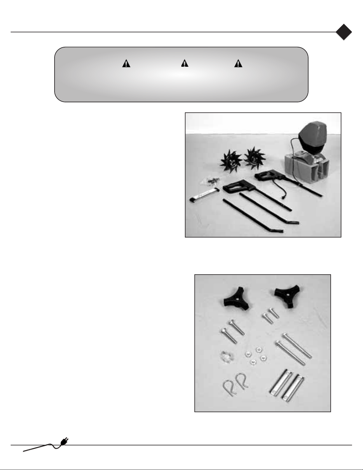
First, take all items out of the carton. But do not
remove the cardboard from around the tiller’s base.
The list below, shows the parts that come with your
tiller. Check to make sure you have them.
The bag of hardware is in the plastic bag containing
the owner’s manual and video.
To assemble your MANTIS Electric Tiller, you’ll
need two 7/16" (11 mm) wrenches. We suggest that
you install all nuts and bolts only “finger tight” —
that is, one-half to one full turn — until you’ve
completed assembly. The nuts are self locking, but
you must use a wrench to tighten them completely.
Qty. Description *Key no.
1 Upper handle assembly 7
1 Upper handle trigger assembly 1
2 Lower handles 10
1 Pair tiller/cultivator Tines 54/55
1 Motor assembly (includes fender
guard, worm gear transmission
& complete housing) 62**
1 Handle brace 14
1 Bag of hardware containing:
2 Round head square neck bolts 16
4 Lock nuts 17
2 Bolts (7.6 cm long) 20
2 Tine retaining pins 53
2 Handle clamps 19
2 Bolts (2.5 cm long) 13
2 Knobs 12
2 Cable clamp 18
*These numbers are the same numbers shown on the parts layout on
pages 16 and 17.
**This key no. is for assembly purposes only.
12
20
13
16
18
53
17
19
62
54, 55
14
1
7
10
A. Parts
Electric tiller
5
Page 8

B. Lower handle assembly
To identify part numbers, see page 5 and 17.
1. Use the protective cardboard sleeve to stabilize
your tiller. Stand the motor assembly (no. 62) up.
(Picture 1)
2. Lay the handle parts within easy reach. You’ll need
one of the handle clamps (no. 19) and one of the
lower handles (no. 10). Note that the lower handles
have a short leg on one end.
3. Fit the handle clamp along the outside of the short
leg. Line up the holes on the clamp and the leg.
4. Choose one of the two 3-inch bolts (no. 20). Slide
it through the first set of holes — near the elbow
where the lower handle curves. (Picture 2)
5. Now slide the other lower handle onto the 3-inch
bolt. Fit the other clamp onto this other handle’s short
leg. Add a nut and tighten finger tight. (Picture 3)
6. Locate the worm gear housing. It starts just
above — and extends down through — the tiller’s
red fender guard. You’ll notice that there’s a
recessed channel on either side of the housing’s top.
(Picture 4.)
7. Take the lower handles that you’ve just put
together. Slide them into the two recessed
channels.(Picture 5.)
Make sure you insert them from the rear of the tiller so that the bolt fits along the back of the housing.
8. Slide the second 3-inch bolt through the second set
of holes in the short legs and clamps. Add a nut and
tighten finger tight.
Picture 1
Picture 2
Picture 3
Picture 5Picture 4
NOTE: THE NUTS ARE SELF LOCKING,
BUT YOU MUST USE A WRENCH TO
TIGHTEN THEM COMPLETELY.
Electric tiller
6
Page 9

C. Upper handle assembly
1. Attach the upper handle assembly (no. 1) – the
handle with the power cord – to the right lower
handle (no. 10) and secure with the handle knob
(no. 53). (Picture 1 and 2)
2. Follow the same steps to install the left upper
handle onto the left lower handle. (Picture 3)
3. Use the clip (no. 18) to secure the power cord
in place on the lower handle. (Picture 4)
4. Now install the handle brace (no. 14). Line it
up with the holes on the upper handles. Then
insert a bolt (no. 13) and a lock nut (no. 17) on
either side (Picture 5)
5. Use a wrench to tighten Bolt (no. 13) and
lock nuts (no. 17).
6. Now use wrench to tighten all nuts and bolts
firmly and securely.
Picture 1
Picture 2
Picture 3
Picture 5
Picture 4
WARNING DANGER
FOR PROPER INSTALLATION - THE HANDLE
WITH THE THROTTLE MUST BE ATTACHED
TO THE RIGHT SIDE LOWER HANDLE.
Electric tiller
7
Page 10
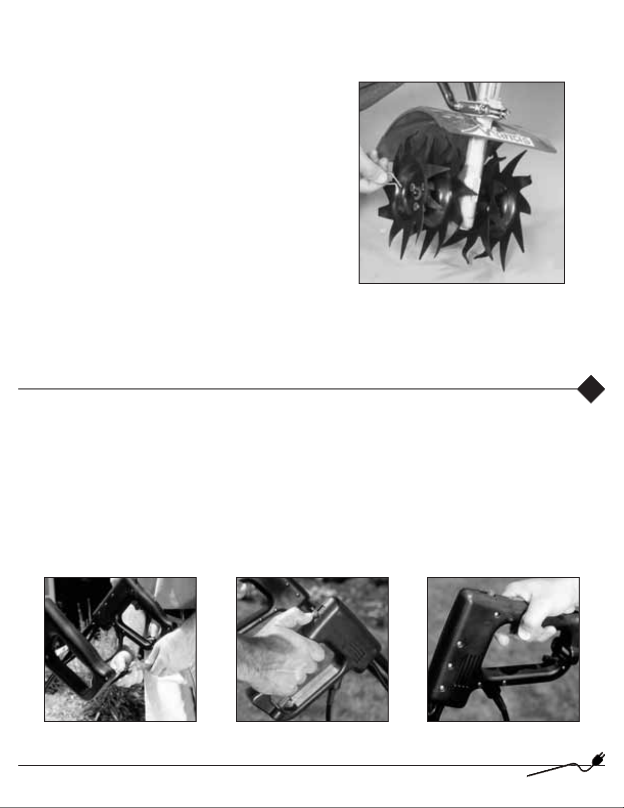
D. Assemble the tines for tilling
Assembling the tines for tilling
1. Remove the cardboard from around your
Tiller’s base.
2. Slide the tines onto the axle shafts. The “D” hole
goes on the outside.
3. Make sure you’ve installed the tines properly for
tilling. Liken the tines to your fingers. When your
palm faces the ground, your fingers curl down. Stand
behind the Tiller and hold your hand next to the tines.
Do the tine blades curl down, as your fingers do? If
so, they are in the tilling position. (To switch to the
cultivating position, see page 12.)
4. To secure each tine to the axle, insert a tine
retaining pin.
IMPORTANT NOTE:
Before you use your MANTIS tiller, read the safety rules & warnings on pages 2-4.
Before you begin tilling
A. Starting
Starting your MANTIS Electric Tiller is easy.
1. Simply loop your extension cord through the built-in extension cord holder. This is provided to secure the
extension cord and help prevent it from becoming detached.
2. Connect the extension cord to the power cord on the tiller. (Picture 1)
3. Plug the extension cord into an outlet.
4. Pick a speed. (Picture 2)
5. Squeeze the triggers to begin tilling. (Picture 3)
Picture 1
Picture 2
Picture 3
Electric tiller
8
Page 11

B. Getting your tiller to the garden
Walk it.
Put the tiller in 1st speed; you can “walk” it to your
garden. Just squeeze the triggers and let the tiller “tiptoe” across your yard on its tines. It won’t hurt your
lawn or driveway. (Picture 1)
Carry It.
Make sure the power cord is unplugged from the
extension cord. Then use one hand to grasp the
convenient carrying handle. Use the other hand to
hold the handlebars. (Picture 2) Then lift your tiller
and carry it to your garden. Since it weighs only 21
pounds, it won’t strain your muscles or tire you out!
Take It for a Ride.
You can easily transport your MANTIS Electric Tiller
to a friend’s or relative’s house. Simply fold down the
handles, then store your tiller in the trunk of your
automobile or truck. It fits easily. And you can put it
in and take it our without straining your back.
(Picture 3)
Picture 1
Picture 2
Picture 4Picture 3
WARNING DANGER
NEVER CARRY YOUR TILLER AS THE PERSON IN
PICTURE 4 IS DOING. IF YOU DO, AND THE TINES
ENGAGE,YOU COULD SUFFER SERIOUS INJURY.
Electric tiller
9
Page 12

Tilling
WARNING DANGER
THE OPERATOR OF THIS TILLER IS RESPONSIBLE FOR ACCIDENTS
OR HAZARDS OCCURRING TO HIMSELF, OTHER PEOPLE
OR THEIR PROPERTY.
A. Now you’re ready to use your MANTIS Electric Tiller
If you’ve seen other tillers, your MANTIS Electric
Tiller may surprise you. It tills best when you pull it
backward! When you pull your MANTIS Electric
Tiller backward, you give extra resistance to the tines,
so they dig deeper. (Picture 1).
What’s more, when you go backward, you erase
footprints. So your soil stays light and fluffy. While
other tillers, by contrast, you walk right over the soil
you’ve just tilled, packing it down.
B. Run your MANTIS Electric Tiller like a vacuum
Place your tiller at the head of the row or area you
want to till. Turn it on. Then use an easy rocking
motion. First, pull your Tiller backward. Then use an
easy rocking motion. Again, pull your tiller backward.
Then let it move forward just a little bit. Then pull it
backward again. This will help you till deeper.
Keep repeating these steps until you’ve tilled an entire
row. Start again on the next row. It’s a lot like running
a vacuum. (Picture 2)
C. You can even control depth
For deeper tilling:
Move your tiller slowly back and forth, as you would
a vacuum cleaner. Work the same area over and over
until you’ve dug to your desired depth. (Picture 3)
For shallow tilling:
Switch the tines to the cultivating position. (See pg.
12 to learn how) Then move you tiller quickly over
your soil surface.
For big weeds or tough roots
Let your tiller rock back and forth over the tough
spot, until the tines slice through the weed or root.
Picture 1
Picture 2
Picture 3
Electric tiller
10
Page 13

D. Your MANTIS Electric Tiller handles special tilling projects
Want to turn part of your lawn into a colorful flower
border?
Your MANTIS Electric Tiller makes it easy! Just run
your tiller back and forth until the sod begins to break
up. Then continue tilling. Your tiller will chop the
clumps of sod until they’re fine. Then, it will work
them into the soil. Pretty soon, you’ll have a soft,
fresh planting bed.
Tilling/cultivating
A. How About a family-size vegetable garden?
Nowadays many gardeners prefer small gardens —
especially in the suburbs, where space is at a
premium. But, if you’re fortunate enough to own a
large lot, you can create a bigger garden — a half
acre or more. Here’s how:
1. First, hire someone with a tractor or big tiller to
break ground for you. This is a one-time-only
investment that’s well worth the small cost.
2. Then, use your tiller to break up any remaining
clumps of soil or sod. Unlike a tractor or big tiller,
your MANTIS Electric Tiller is a precision tool. It
will pulverize your soil into a smooth seed bed.
WARNING DANGER
IF YOUR TINES GET JAMMED OR ENTANGLED,TURN OFF THE
TILLER AT ONCE. REMOVE THE OBSTRUCTION ONLY WHILE
THE TILLER IS UNPLUGGED.
NEVER TRY TO REMOVE AN OBSTRUCTION WHILE THE TILLER IS IN
THE ON POSITION OR PLUGGED IN. SERIOUS INJURY CAN RESULT.
B. Your MANTIS Electric Tiller makes weeding a pleasure!
As a tiller, your MANTIS Tiller works the soil down
to 10" (25.4 cm) deep. But, as a cultivator, it gently
cultivates the surface, only 2" to 3" (5.09 cm to 7.62
cm) deep.
First, you must switch the tines to the weeding
position. This takes less than a minute.
Then, your MANTIS Electric Tiller’s sharp “tine
teeth” will slice up those pesky weeds, burying them
as you go along. And, since the tines in this position
won’t dig too deep, they won’t hurt your plants’
precious root systems.
The result? Your tiller will cut your weeding time in
half, and turn a tiresome chore into a pleasure.
Electric tiller
11
Page 14

C. How to switch from tilling to cultivating position
1. Make sure your Tiller is off and unplugged.
2. Remove the retaining pins from the tines.
3. Remove the tines from the axle.
4. Place the right-side tine onto the left-side axle.
Place the left side tine onto the right-side axle. The
“D” hole should be to the outside.
5. Here is how to make sure you’ve installed the tines
properly. Stand behind the tiller and hold your hand,
palm up, next to the tines. Do the tine points curl up,
as your fingers do? If so, they are in the correct
cultivating position. (See photos below)
6. Reinsert the pins.
D. Now You’re Ready to cultivate or weed.
Guide your tiller where you want to weed and start it
up. Pull your tiller backward slowly, then let it move
forward a bit, in a gentle rocking motion. Watch it
slice, shred, and bury those weeds!
Got tough weeds? Select a slower speed to slow your
Tiller down. Then work back and forth until your
Tiller chops up the weeds. It’s easy and effective!
Remember, any tiller will tangle in tall grass, stringy
vines, or super-big weeds. So, if you have a
“backyard jungle,” first use a knife, pruner, or brush
cutter to chop up the overgrowth. If the tines become
tangled anyway, turn the motor and unplug the tiller
before trying to clear them.
The optional tine Detangler (Item no. 1322) will clear
tines in a jiffy. Contact your local authorized
MANTIS dealer.
E. Your MANTIS Electric Tiller will weed between narrow rows!
Your MANTIS Electric Tiller is a precision weeder
that easily fits in tight places. So don’t be afraid to
weed anywhere: between plants and shrubs; in
corners; against fences; on raised beds; in wide rows;
even in very narrow rows. Your MANTIS Electric
Tiller weeds 25* to23 cm wide. So you can run it in a
tightly planted garden without damaging your delicate
plants. That’s good news for suburban gardeners, who
often have to plant rows close together!
*With optional Planter/ Furrower attachment (Item no. 6222.)
Tilling position
Tine teeth point in the
same direction as the
rotation of the tine; or
toward the front of the
Tiller, away from the
operator.
Cultivating position
Tine teeth point in the
opposite direction as
the rotation of the tine.
Tines point toward the
back of the tiller, or
toward the operator.
Back Front Back Front
Tine
rotation
Tine
teeth
Tine
rotation
Tine
teeth
Electric tiller
12
Page 15

Using the Border Edger attachment
Your MANTIS Electric Tiller has been designed and
built to accept a wide range of MANTIS Electric
Tiller attachments to increase its usefulness in your
lawn and garden. And, all MANTIS Electric Tiller
Attachments have been designed for quick and easy
attachment to the tiller or engine.
The Border Edger (Item no. 3222)
The most popular attachment, the Border Edger can
be used to cut clean, neat edges along walkways, or
around trees, shrubs, and
garden beds.
The Border Edger has two
parts: a wheel and a
hardened steel blade, with
pointed tines.
How to install the Border
Edger
The following instructions
refer to “right” and “left”
axles. Assume that you’re
standing behind your
Tiller, as you would for
tilling and cultivating.
Some areas of your yard may harbor roots and other
underground obstructions. In places like this you’ll
want to edge your borders shallowly (2.5 to 5 cm
deep). Here’s how to install the Border Edger for
shallow edging:
1. First remove your tilling/cultivating tines.
2. Then slide the edger’s wheel onto the right axle.
3. Now slide the Edger blade onto the left axle. The
blade’s angled face should hit the ground when you
spin the blade forward. (Picture 2)
4. Insert retaining pins on both left and right axles.
Around walkways and garden beds, you’ll want to
edge more deeply (7.5 to 10 cm deep). Here’s how to
install the Border Edger for that purpose:
1. Remove the tilling/cultivating tines.
2. Slide the edger’s blade onto the right axle. The
blade’s pointed face should hit the ground when you
spin the blade forward. (Picture 1)
3. Slide the wheel onto the left axle.
4. Insert retaining pins on both sides.
How to use the Border Edger
1. Position your MANTIS Electric Tiller so that the
edger blade is right along the garden edge and the
wheel is outside (on the lawn, on the sidewalk,
wherever). (Picture 2)
2. Start your tiller and pull your MANTIS backward
along the garden edge.
The Border Edger can handle special projects!
1. Install the Edger for deep edging, as directed
above. Then use it to cut sod strips.
2. Edge and weed at the same time! Just attach the
edger blade on one axle and a tiller tine on the other
axle, “Mix and match” blades; don’t be afraid to
experiment.
IMPORTANT NOTE:
If you do a lot of edging, you’ll appreciate the
MANTIS Wheel Set (Itemno. 9222.) It gives you
added stability, for even easier handling.
To order the Wheel Set, or any MANTIS attachment,
contact your local authorized MANTIS dealer.
Picture 1
Picture 2
Electric tiller
13
Page 16

1. If nothing happens when you squeeze the triggers,
make sure the tiller is plugged in or that the cord is
not damaged.
2. If it still does not work, unplug the Electric Tiller
from the power source.
3. Inspect the tines to make sure your tines are clear
of rocks or debris. Clear any debris that may be
preventing the tines from spinning.
4. Remove the tines to make sure all of the debris has
been cleared.
5. Check the circuit breaker on the Electric Tiller.
Make sure the button hasn’t popped.
6. If the button has popped, press the button back in.
If the circuit breaker button doesn’t stay in, wait
approximately 30 seconds and retry. (Picture 1)
7. Make sure that the circuit breaker hasn’t been
tripped at your power source: whether it’s your
house, a generator, or an outdoor outlet.
Picture 1
Troubleshooting
A. What to do if your Electric Tiller stops running
B. How to reseat the motor housing
At some point, you may find that the tines won’t turn
when you squeeze the throttle. This may mean the motor
isn’t sitting all the way down on the worm gear housing.
Perhaps you’ve been using your Tiller for several
years. The housing screw bolt (Key no. 22) may have
come loose and lifted the motor up.
If this happened you’ll notice a gap between the
bottom of the bottom housing (Key no. 24) and the
top of the worm gear housing. (Picture 2)
To fix this, loosen the housing screw. Take the motor
and housing off the worm gear housing. Notice the
hex head on top of the drive shaft (Key no. 21). Inside
the bottom housing, you’ll find the coupler driver
(Key no. 26). Make sure the hex head lines up with
the coupler driver inside the bottom housing.
Then put the motor back on the worm gear housing.
If you’ve followed these steps properly, there will be
no gap between the bottom housing and the worm
gear housing. (Picture 3) Make sure you tighten the
housing screws!
C. The tines don’t seem to dig like they used to
If the tines are not performing as they did when you
first bought the tiller, inspect them for excessive
wear. If they are worn, you can order a new pair
direct from MANTIS.
To order replacement tines contact your local
authorized MANTIS dealer.
IMPORTANT NOTE:
To keep your MANTIS Electric Tiller running as
efficiently as possible, always make sure the tines
are clear of rocks and debris.
If you continue to experience problems, contact
your local authorized MANTIS dealer.
Picture 2
Picture 3
Electric tiller
14
Page 17

Storage
1. Clean dirt, grass and other materials from the entire
machine.
2. Wipe the tines with oil or spray them with WD-40,
to prevent rusting.
3. Check the grease level in the gear housing, as
described on page 13.
4. Order new parts to replace any that are badly worn
or broken. Contact your local authorized MANTIS
dealer.
5. Store your tiller in a clean, dry place. You can store
with the handles in an extended position (Picture 3) or
folded down. (Picture 4)
6. To fold down the handles, follow these easy steps:
Loosen the handle knobs (no. 12), fold the handles
forward or back. (Picture 4) Tighten knob securely.
Your handles are now folded and ready to store in a
smaller area.
Picture 3
Picture 4
IMPORTANT NOTE:
Handles can fold back or forward. When folding
handles back, as show in picture no. 4, be careful
not to damage the 3-speed switch.
Maintenance
A. How to check the grease level inside the worm gear housing
When we built your MANTIS Electric Tiller, we
lubricated the worm gear housing thoroughly.
It is imperative that you inspect the grease level once
a year. Simply remove the cover plate on the worm
gear housing. (Picture 1) Then check to make sure the
grease comes almost to the top of the housing. If it
doesn’t, add lithium no. 0 grease (Item M9985.) This
is the only way to add grease to the worm gear
housing. (Picture 2) To purchase MANTIS grease,
contact your local authorized MANTIS dealer.
Please do not overfill. Too much grease can create
pressure, which could cause seals to fail or the clutch
to slip.
Picture 1
Picture 2
Electric tiller
15
Page 18

Parts explosion
P/N 438LA
P/N 438RA
DIRECTION
Raised hub
Teeth point in
a clockwise
direction
DIRECTION
Raised hub
Teeth point in
a counter
clockwise
direction
When you look at a tine with the raised hub facing you
and the teeth are pointing in a CLOCKWISE rotation,
you have a LEFT HAND TINE.
When you look at tine with the raised hub facing you and
the teeth are pointing in a COUNTER CLOCKWISE
rotation, you and a RIGHT HAND TINE.
Electric tiller
16
Page 19

Parts list
Electric tiller
17
Key No.
1
2
3
4
5
6
7
8
9
10
11
12
13
14
15
16
17
18
19
20
21
22
23
24
25
26
27
28
29
30
31
32A
32B
Part No.
420200
420115
420203
3033
420124
310500
420207
420137
420213
420214
400230
400510
400509
420113
420602
410
972
478
377
470
468
420513
420514
420134
420512
420224
420222
420223
420511
420107
420910
420132
420142
Qty.
1
1
1
1
1
24
1
1
2
2
2
2
2
1
1
2
4
2
2
2
1
1
1
1
6
1
1
1
4
1
1
1
1
Description
Handle, Right Side Assy
Power Cord
Trigger, Trigger lock, Button
Switch Normally Open
Assembled PC Board w/Switch
#8-11 x 3/4 Combo Sl Torx T-20 Pan
Steel Plastite 45-1 Case Harden
Handle, Left Side Assy
Motor Cord
Handle Upper FDH- Black
Handle Lower FDH- Black
Plug Handle
Handle Knob
Bolt
Handle Brace
Label Brace Elec. Tiller
Cap Screw 1/4-20 x 1" Lg.
Locknut 1/4-20
Cable Clamp
Handle Clamp
1/4-20 x 3" Bolt
Drive Shaft (Also in Key #61)
8-32 x 7/8 6-Lobe Torx Equiv Pan
M/S, with T-20 Driver Size
8-32 Hex Machine Screw Nuts,
Steel, Zinc
Bottom Housing
10-32 x 1/2 6-Lobe Torx Equiv Pan
M/S, with Spec T-20 Driver Size
Coupler Driver
Coupler Shock Absorber
Coupler Housing
1/4-20 x 1/2 Socket Head Cap Screw,
Plain Steel
Motor Mounting Plate
230V PM Motor
Left Housing Half
Right Housing Half w/230v Circuit Breaker
Key No.
32C
33
34
35
36
37
38
39
40
41
42
43
44
45
46
47
48
49
50
51
52
53
54
55
56
57
58
59
61
62
63
64
Part No.
420145
420138
3016
3041
466
432
434
435
431
423
425
424
400204
458
426
428
430
400205
436
437A
651
418-1
438LA
438RA
465
140
420600
4058
400011
420147
420110
420139
Qty
1
1
1
2
1
2
2
2
1
1
2
1
1
1
1
1
2
1
1
1
4
2
1
1
1
2
1
1
1
1
1
1
Description
Right Housing 230v w/o Circuit Breaker
(can be sold as a replacement part)
Circuit Breaker
Strain Relief
3.5 x 13mm Ph Pan Metric Tapping
Screw DIN 7981, Steel, Zinc
Worm Gear Housing
Worm Gear Bearing
Bearing Seal
Bearing Seal Retainer
Tine Shaft
Roller Bearing
Worm Bearing Race
Worm Thrust Bearing
Worm
Roller Bearing
Worm Disk
Retaining Ring
Worm Gear Thrust Washer
Worm Gear
Gasket
Housing Cover
Rd. Hd. Self Tapping Screw
Tine Retaining Hair Pin
Tine Assembly (L.H.)
Tine Assembly (R.H.)
Fender Guard
Bolt 1/4-20 x 3/8" Lg.
Warning Fender Label
Mantis Label
Electric Tiller Trans w/ drive shaft
Ferrite Core Assembly
Spring
Conversion Cord (Not Shown)
Page 20

Electric tiller
18
Page 21

DE Name, Vorname: Bryan, Stuart DE Stellung: Präsident
Electric tiller
19
FR Nom, Prénom : Bryan, Stuart FR Poste : Président
GB Surname, First Name: Bryan, Stuart GB Position: President
NL Naam, Voornaam: Bryan, Stuart NL Positie: President
ES Apellido, Nombre: Bryan, Stuart ES Posición: Presidente
IT Cognome, Nome: Bryan, Stuart IT Posizione: Presidente
SE Namn, Förnamn: Bryan, Stuart SE Position: President
DK Navn, Fornavn: Bryan, Stuart DK Stilling: Direktør
NO Navn, Fornavn: Bryan, Stuart NO Stilling: President
FI Sukunimi, etunumi: Bryan, Stuart FI Asema: Toimitusjohtaja
SOUTHAMPTON, PA. USA January 6, 2004 Stuart Bryan
DE Ort. Datum, Unterschrift GB Place, Date, Signature ES Lugar y fecha, Firma SE Ort, Datum, Underskrift
FR Lieu, Date, Signature NL Plaats, Datum, Handtekening IT Luogo e date, Firma DK Sted, dato, Underskrift
NO Sted, og, Underskrift FI Paikka, Päivämäärä, Allekirjoitus
Page 22

Electric tiller
20
For repair or refunds!
Please, provide the following information if you return a product for repair or if you request a refund.
Name:
Address: City, Postcode:
Phone (day): Phone (evening):
Customer No:
(not necessary but helpful)
Product(s) being returned:
For ® Repair ® Refund ® Other
Repair:
If you return a product or part for repair or for a cost estimate,
please indicate what could be damaged.
Refund:
If you are requesting a refund, please tell us why:
® Product is different than I expected
® Not satisfied with performance
® Not satisfied with quality
® Other
Disassemble the machine or part and wrap it in a sturdy box; send it back to us. Thank you.
Page 23

21
Electric tiller
Page 24

P/N 420702 01/04
©2004 Mantis. Schiller-Pfeiffer, Inc. All Rights Reserved. Printed in USA
Tines Guaranteed
Our tines not only work better than the rest: they’re also
guaranteed for 5 years against breakage. If any tine breaks in
normal use, send the broken tine back to us and we’ll send you
a replacement tine FREE!
Two-year Warranty
All components of the Mantis Tiller/Cultivator are warranted
for a period of two full years from the date of purchase. If any
part fails to work because of defects in materials or
workmanship, we will repair or replace the part at no charge to
you.
Lifetime Service
If you ever need Mantis parts, we’ll get them right out to you.
Usually shipped within 48 hours (and, if a major repair is ever
required, we’ll do it quickly and reasonable).
Please have this information when you call:
1. Date of purchase
2. Date machine was first used
3. Serial Number , located on top of engine
4. Customer number, if available
Please Call us First!
If you are having any trouble with any Mantis product, please call
us. Ask for the Customer Service Dept. Usually, we can solve most
problems over the phone.
Limited warranty information for
Mantis tiller
Mantis extends only to the original consumer purchaser a
limited warranty against defects in material and workmanship
for a period of two years from date of purchase. This warranty
covers all portions of the Mantis Tiller.
Mantis will repair or, at its option, replace any defective part or
parts of the product free of charge. In the event of a defect or
malfunction, the purchaser must return the product to Mantis.
Mantis assumes no responsibility in the event that the product
was assembled or used in contravention of any assembly, care,
safety, or operating instructions contained in the Owner’s
Manual; was not used with reasonable care; or was used for
other than normal and intended purposes.
Mantis makes no express warranties or representation except
those contained herein. The duration of any implied warranty,
including merchantability and fitness for a particular purpose, is
limited to the duration of the express warranty. Mantis
disclaims all liability for indirect and/or consequential
damages.
Some states do not allow limitations on how long an implied
warranty lasts and/or do not allow the exclusion or limitation of
incidental or consequential damages, so that above limitations
and exclusions may not apply to you. This warranty gives you
specific legal rights.
The Mantis promise
Try any product you buy from Mantis with NO-RISK! If you’re not
completely satisfied, send it back to us within 100 days for a
complete, no-hassle refund. All you have to pay is the return insured
postage.
Mantis GmbH
Europa-Strasse 31
CH-8152 Glattbrugg
Tel.: 0800-110 111
Fax: 0800-110 222
Email: info@mantis.ch
Mantis Deutschland GmbH
Industriehof Trecknase 10
D-42897 Remscheid
Tel.: 0180-3000 208*
Fax: 0180-3000 209
Email: info@mantis-europe.de
*(9 Cent/Min.)
Mantis France SARL
20, rue des Garennes
F-57155 Marly
Tél. : 0810 21 18 65
Fax: 0387 62 88 89
Email: info@mantis.fr
Mantis UK Limited
Orchard House
Hempshaw Lane
Stockport, Cheshire SK1 4LH
Tel.: 08454-58 58 68
Fax: 0161 477 9144
Email: info@mantis-uk.co.uk
If you need to return a product – call first
Very few customers ever need to return a Mantis product, but just
in case you have to …here are some simple instructions that will
help us serve you quicker and better.
Please clean the product if it has been used.
Give us as much information as possible, so that we can help you
as quickly as possible.
Please provide information requested on form and send the
completed form with your product.
 Loading...