

Mantis 7234 DELUXE Owner's Manual

7234 DELUXE 2-CYCLE TILLER/CULTIVATOR
OWNER’S MANUAL
IMPORTANT!
ASSEMBLY INSTRUCTIONS START ON PAGE 5!
PLEASE REVIEW THE WARNING & SAFETY INFORMATION ON PAGES 3-4
AND THE ASSEMBLY INSTRUCTIONS BEFORE UNPACKING THE BOX.
2
TABLE OF CONTENTS
Safety Rules & Warnings
. . . . . . . . . . . . . . . . .
3-4
Assembly and Mixing Fuel . . . . . . . . . . . . . .5-12
Starting . . . . . . . . . . . . . . . . . . . . . . . . . . . .12-13
Additional Information . . . . . . . . . . . . . . . . . .13
What to Do Just in Case . . . . . . . . . . . . . . .13-14
Getting to Your Garden . . . . . . . . . . . . . . . . . .14
Tilling . . . . . . . . . . . . . . . . . . . . . . . . . . . . .14-15
Service Maintenance Guide & Specifications . . .15
Tilling/Cultivating . . . . . . . . . . . . . . . . . . . . . .16
Tine Positioning . . . . . . . . . . . . . . . . . . . . . . . .16
Maintenance . . . . . . . . . . . . . . . . . . . . . . . .17-18
Storage . . . . . . . . . . . . . . . . . . . . . . . . . . . . . . .19
Trouble Shooting . . . . . . . . . . . . . . . . . . . . . . .20
MANTIS Tiller Assembly Layout . . . . . . . . . . .21
Engine Parts Assemblies . . . . . . . . . . . . . . .22-24
EPA Phase 2 Emission . . . . . . . . . . . . . . . . . .25
Limited Warranty Information . . . . .Back Cover
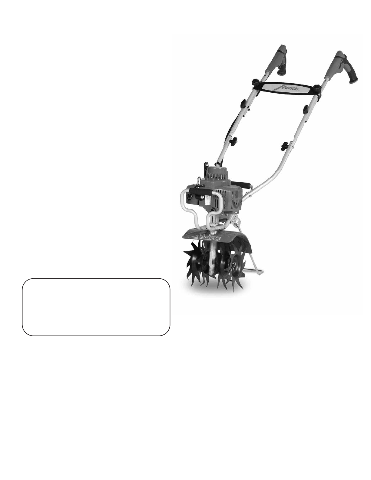
Here’s your new MANTIS Tiller...
the lightweight wonder that “Makes
Gardening Easier.”
Unlike big tillers, your MANTIS Tiller
weighs only 25 pounds. So it lifts easily,
handles smoothly, tills and weeds precisely.
And, unlike other small tillers, it features
serpentine tines that churn soil up to ten
inches deep. It creates a soft, smooth seed
bed, even in problem soil.
Once you know how to use your tiller
correctly, we guarantee you’ll love it. So
first, please read this manual. It shows, step
by step, how to use your tiller safely.
If you have questions about any topic in
this Manual, or for the name of your local
dealer, call 1-800-366-6268 toll free,
Monday - Saturday, 8:00 a.m. to 5:00 p.m.,
Eastern Time.
Attention Mantis Product
Owners! Get maintenance tips
for your Mantis product on our
website at www.mantis.com
WELCOME TO THE WORLD
OF MANTIS GARDENING!

3
SAFETY RULES & WARNINGS
You will notice throughout this Owners Manual Safety Rules and Important Notes. Make sure you
understand and obey these warnings for your own protection.
I. Special Safety Information
WARNING • DANGER
ATTENTION: THIS SYMBOL POINTS
OUT OUR IMPORTANT
SAFETY INSTRUCTIONS.
WHEN YOU SEE THIS SYMBOL,
HEED IT’S WARNING!! STAY ALERT!!
WARNING • DANGER
TO REDUCE THE POTENTIAL FOR ACCIDENTS,
COMPLY WITH THE SAFETY INSTRUCTIONS
IN THIS MANUAL.
FAILURE TO COMPLY MAY RESULT IN SERIOUS
PERSONAL INJURY, AND/OR EQUIPMENT
AND PROPERTY DAMAGE.
WARNING • DANGER
IMPROPER USE OR CARE OF THIS TILLER OR FAILURE TO WEAR PROPER
PROTECTION CAN RESULT IN SERIOUS INJURY.
READ AND UNDERSTAND THE RULES FOR SAFE OPERATION
AND ALL INSTRUCTIONS IN THIS MANUAL.
WEAR HEARING AND EYE PROTECTION.
II. Safety & Warnings
!
!
! !
!
!
!
WARNING
The Engine Exhaust from this
product contains chemicals known
to the State of California to cause
cancer, birth defects or other
reproductive harm.
!
DON’T FUEL, REFUEL,
OR CHECK FUEL WHILE
SMOKING, OR NEAR AN
OPEN FLAME OR
OTHER IGNITION
SOURCE.
MIX UNLEADED GAS
WITH 2 CYCLE 50:1 OIL.
INCORRECT ASSEMBLY.
CAUTION: WHEN ASSEMBLING
THE HANDLES, MAKE SURE
FUEL TANK FACES OPERATOR.
THIS IS THE REAR OF THE
TILLER, REFER TO ASSEMBLY
INSTRUCTION ON PAGE 7.
CUTTING HAZARD; KEEP
FEET AND HANDS AWAY
FROM ROTATING TINES.
WEAR EAR AND EYE
PROTECTION.
READ OWNER’S MANUAL
BEFORE USING TILLER, OR
PERFORMING ANY REPAIR
OR MAINTENANCE. KEEP
OWNERS MANUAL IN A
SAFE PLACE.
DO NOT CARRY THE
TILLER IN THIS
POSITION.
An important part of the safety system incorporated in this tiller are the warning
and information decals found on various parts of the tiller. These decals must be replaced
in time due to abrasion, etc. It is your responsibility to replace these decals when they
become hard to read. The location and part numbers (P/N) of these decals are illustrated on Page 16.
III. Safety Decal Information
WARNING • DANGER
IF THE TILLER IS USED IMPROPERLY OR SAFETY PRECAUTIONS ARE NOT FOLLOWED,
THE USERS RISK SERIOUS INJURY TO THEMSELVES AND OTHERS. READ AND
UNDERSTAND THIS MANUAL BEFORE ATTEMPTING TO OPERATE THIS TILLER.
!
!
WARNING • DANGER
OPERATION OF THIS EQUIPMENT MAY CREATE SPARKS THAT CAN START FIRES
AROUND DRY VEGETATION. A SPARK ARRESTOR IS INSTALLED. THE OPERATOR
SHOULD CONTACT LOCAL FIRE AGENCIES FOR LAWS OR REGULATIONS RELATING
TO FIRE PREVENTION REQUIREMENTS.
!
!
DON’T OPERATE
INDOORS
PRODUCT EMISSION DURABILITY
The 300 hour emission durability compliance
period is the time span selected by the manufacturer
certifying the engine emissions output meets
applicable emissions regulations, provided that
approved maintenance procedures are followed
as listed in the Maintenance Section of this manual.
An Emission
Control Label is
located on the engine
(This is an EXAMPLE
ONLY, information on
label varies by
engine FAMILY.)
EMISSION CONTROL
The emission control system for the engine is EM/TWC (Engine
Modification and 3-way Catalyst) and for the fuel tank the Control
System is EVAP (Evaporative Emissions) or N (for nylon tank).
Evaporative emission may be applicable to California models only.
P/N 400630
P/N 430057

V. Warnings - Don'ts
Don’t use tiller with one hand.
Keep
both hands on handles with
fingers and
thumbs encircling the handles, while tines
are moving, and engine is running.
Don’t overreach. Keep a good footing at
all times.
Don’t run with the machine, walk.
Don’t work on excessively steep slopes.
Don’t attempt to clear tines while they
are moving. Never try to remove jammed
material before switching the engine off
and making sure the tines have stopped
completely.
Don’t allow children or incapable
people to operate this tiller.
Don’t operate while under
the influence of alcohol or drugs.
Don’t attempt to repair this tiller. Have
repairs made by a qualified dealer or
repairman. See that only original MANTIS
parts are used.
WARNING • DANGER
HANDLE FUEL WITH CARE, IT IS HIGHLY FLAMMABLE. FUELING A HOT ENGINE OR NEAR AN IGNITION SOURCE CAN
CAUSE A FIRE AND RESULT IN SERIOUS PERSONAL INJURY AND/OR PROPERTY DAMAGE.
Always use fresh gasoline in the fuel
mixture. Stale gasoline can cause damage.
Always store fuel in containers
specifically designed for this purpose.
Always pull starter cord slowly until
resistance is felt. Then pull cord rapidly to
avoid kickback and prevent arm or hand
injury.
Always operate engine with spark
arrestor installed and operating properly.
The use of spark arrestor mufflers is
required by law in the state of California
(Section 4442 of the California Public
Resources Code), as well as in other states
or municipalities. Federal laws apply on
federal lands.
Stop the engine whenever you leave the
machine.
Allow the engine to cool before storing
in any enclosure.
If the fuel tank needs to be drained, this
should be done outdoors.
Don’t
fuel, refuel or check fuel while
smoking, or near an open flame or other
ignition source. Stop engine and be sure it is
cool before refueling.
Don’t
leave the engine running while the
tiller is unattended. Stop engine before
putting the tiller down or while transporting
from one place to another.
Don’t
refuel, start or run this tiller
indoors or in an improperly ventilated area.
Don’t
run engine when electrical system
causes spark outside the cylinder. During
periodical checks of the spark plug, keep
plug a safe distance from cylinder to avoid
burning of evaporated fuel from cylinder.
Don’t
check for spark with spark plug or
plug wire removed. Use an approved tester.
Don’t
crank engine with spark plug
removed unless spark plug wire is
disconnected. Sparks can ignite fumes.
Don’t
run engine when the odor of gas oline
is present or other explosive conditions exist.
Don’t
operate the unit if gasoline is
spilled. Clean up spill completely before
starting engine.
Don’t
operate your tiller if there is an
accumulation of debris around the muffler,
and cooling fins.
Don’t
touch hot mufflers, cylinders
or cooling fins as contact may cause
serious burns.
Don’t change the engine governor
setting or over speed the engine.
VI. Engine/Fuel Warnings - Do’s
VII. Engine/Fuel Warnings - Don’ts
IV. Warnings - Do’s
Read and understand the owner’s
manual. Pay particular attention to all
sections regarding safety.
1. Always keep a firm grip on both
handles while the tines are moving and/or
the engine is running. BE AWARE!! The
tines may coast after throttle trigger is
released. Make sure tines have come to a
complete stop and engine is off before
letting go of the tiller.
2. Always maintain a firm footing and
good balance. Do not overreach while
operating the tiller. Before you start to use
the tiller check the work area for obstacles
that might cause you to lose your footing,
balance or control of the machine.
3. Thoroughly inspect the area where
equipment is to be used and remove all
objects, which can be thrown by the
machine.
4. Always keep area clear of children,
pets, and bystanders.
5. Always stay alert. Watch what you
are doing and use common sense. Do not
operate unit when fatigued.
6. Always dress properly. Do not wear
loose clothing or jewelry, they might get
caught in moving parts. Use sturdy gloves.
Gloves reduce the transmission of vibration
to your hands. Prolonged exposure to
vibration can cause numbness and other
ailments.
7. While working, always wear
substantial footwear and long trousers. Do
not operate the equipment when barefoot
or wearing open sandals.
8. Always wear ear and eye protection.
Eye protection must meet ANSI Z 87.1. To
avoid hearing damage, we recommend
hearing protection be worn whenever using
the equipment.
9. To reduce fire hazard, keep the
engine, and petrol/gas storage area free of
vegetative material and excessive grease.
10. Start the engine carefully, according
to the manufacturer’s instructions and with
feet well away from tool(s).
11. Keep all nuts, bolts and screws tight
to be sure the equipment is in safe working
condition.
12. Use extreme caution when reversing
or pulling the machine towards you.
13. Work only in daylight or good
artificial light.
14. Always be sure of your footing on
slopes.
15. Exercise extreme caution when
changing direction on slopes.
16. Always keep a safe distance
between two or more people when
working together.
17. Always inspect your unit before
each use and ensure that all handles,
guards and fasteners are secure, operating,
and in place.
18. Always maintain and examine your
Tiller with care. Follow mainten ance
instructions given in manual.
19. Always store tiller in a sheltered
area (a dry place), not accessible to
children. The tiller as well as fuel should
not be stored in a house.
4
!
!
Removing Parts From Box
ASSEMBLY
Step 1
It is best to assemble the tiller
on a hard flat surface such as
a garage floor or driveway.
Step 2
Open top of shipping carton.
Your MANTIS
®
Tiller comes partially assembled.
The full assembly will take just a few minutes if
you follow the directions correctly.
Step 5
Remove component parts and lay on flat surface.
Step 3 Step 4
Remove tine box and oil.
Remove cardboard insert.
Step 6 Step 7 Step 8
Lay box on wide flat side.
Open bottom of the box and
lift box flaps up.
Return box to the standing position.
Do not remove upper
right throttle handle
assembly and engine
portion of the tiller in
this step.
Helpful Hint 1
Keep like items together.
Helpful Hint 2
CAUTION
When removing tine box,
handle the box with
extreme caution, Tines are
sharp and can come
through the cardboard box.
5
Ratchet
7/16” Wrench
3/8” Wrench
Extension
7/16”
Socket
TOOLS
NEEDED
WARNING • DANGER
IMPROPER ASSEMBLY OF THIS TILLER CAN RESULT IN SERIOUS INJURY. MAKE SURE TO FOLLOW ALL INSTRUCTIONS CAREFULLY.
IF YOU HAVE ANY QUESTIONS, CONTACT OUR FACTORY AT 1-800-366-6268 OR AN AUTHORIZED MANTIS DEALER.
!
!
6
ASSEMBLY (continued)
Step 9
Pull box straight up.
The right handle, additional parts and tiller engine will be in the box cradle.
Do not remove the cardboard cradle from around the tiller base. The cradle will make
the assembly process easier for you.
Helpful Hint
Parts List
Lower Handle Assembly
Upper Handle Assembly
Key Qty. Part No. Description
A 1 N/A Transmission and Engine assembly
B
1 430023 Loop handle right half
C 1 430022 Loop handle left half
D 1 430025 Loop handle grip
E 1 430051 Lower handle, right
F 1 430050 Lower handle, left
G2 4049
3.25” Bolts
H 4 972 1/4-20 Two-way lock nut
I 1 430049 Carry Handle (with grip)
J 2 144-2 1/4-20 x 1-1/8 Hex head cap screws
J – 1/4-20 x
1-1/8 Hex head
cap screws
H – 1/4-20
Two-way
lock nut
B, C – Loop Handle
G – 3.25” Bolts
D – Loop handle grip
I – Carry Handle w/grip
E, F – Lower Handle
A – Transmission and
Engine Assembly
E – Right
B – Right
F– Left
C – Left
Key Qty. Part No. Description
H 2 972 1/4-20 Two-way lock nut
J
2 144-2 1/4-20 x 1-1/8 Hex head cap screws
K 1 430003 Trigger handle assembly, right
L 1 430006 Handle assembly, left
M 1 430053 Middle handle, right
N 1 430052 Middle handle, left
O 1 430021 Handle brace
P 2 430038 Knob– 1/4-20 x 1.5 male
Q4 400523
Knob, two prongs, female
R 2 430039 Carriage bolt 1/4-20 x 2.25”
S 2 430048 Curved head bolt, 1/4-20x2”
T 2 395 Acorn nut
U 2 478 Throttle Clip
J –
1/4-20 x 1-1/8 Hex
head cap screws
H – 1/4-20
Two-way
lock nut
S – Curved
Head Bolts
T – Acorn
Nuts
U – Throttle Clips
R – Carriage
Bolts
Q – Knobs, Two-
Prong female
O – Handle Brace
M, N –Middle
handles
P – Knob 1/4-20
x 1.5 male
K, L – Handle Assembly
K-Right
L-Left
M-Right
N-Left
7
ASSEMBLY (continued)
Lower Handle Assembly
Parts Needed:
Tine Assembly
Kickstand Assembly
Step 1
Layout parts.
Step 4
Slide lower left handle onto 3.25” bolts.
Lower Tiller Assembly should look
like above.
Finger tighten
nuts and bolts.
Slide left loop handle (C) into grip (D) and into
right loop handle (B).
Step 3
Place right
lower handle
assembly onto
unit as shown
above.
Step 2
• Insert grip (D)
onto the Right
Loop Handle (B)
• Line up holes on
Right Loop Handle
(B) and Lower
Right Handle (E)
• Place (2) 3.25”
bolts (G) through
holes.
One side only at a time.
Helpful Hint
Finger tight is one half
to one full turn.
Helpful Hint
Keep throttle cable out
of the way.
Helpful Hint
Hold bolts on right side as you put
left side onto the bolts.
Helpful Hint
D
D
B
B
C
B
C
D
FE
E
B, C – Loop Handle
B – Right
C – Left
D – Loop handle grip
H – 1/4-20
Two- way
lock nut
L
L
G – 3.25” Bolts
L
E, F –
Lower Handle
E – Right
B
F– Left
C
Z – Kickstand Brace Kit
Y – Kickstand
Key Qty. Part No. Description
Y1 410158 Stand
Z
1 430037 Kickstand Brace Kit
X – Tine Retaining pinsV, W – Tines
Key Qty. Part No. Description
V 1 438RA Tine assembly, right
W
1 438LA Tine assembly, left
X 2 418-1 Tine retaining pins
4A
4B
4C
4D
4E
A – T
ransmission and
Engine Assembly
8
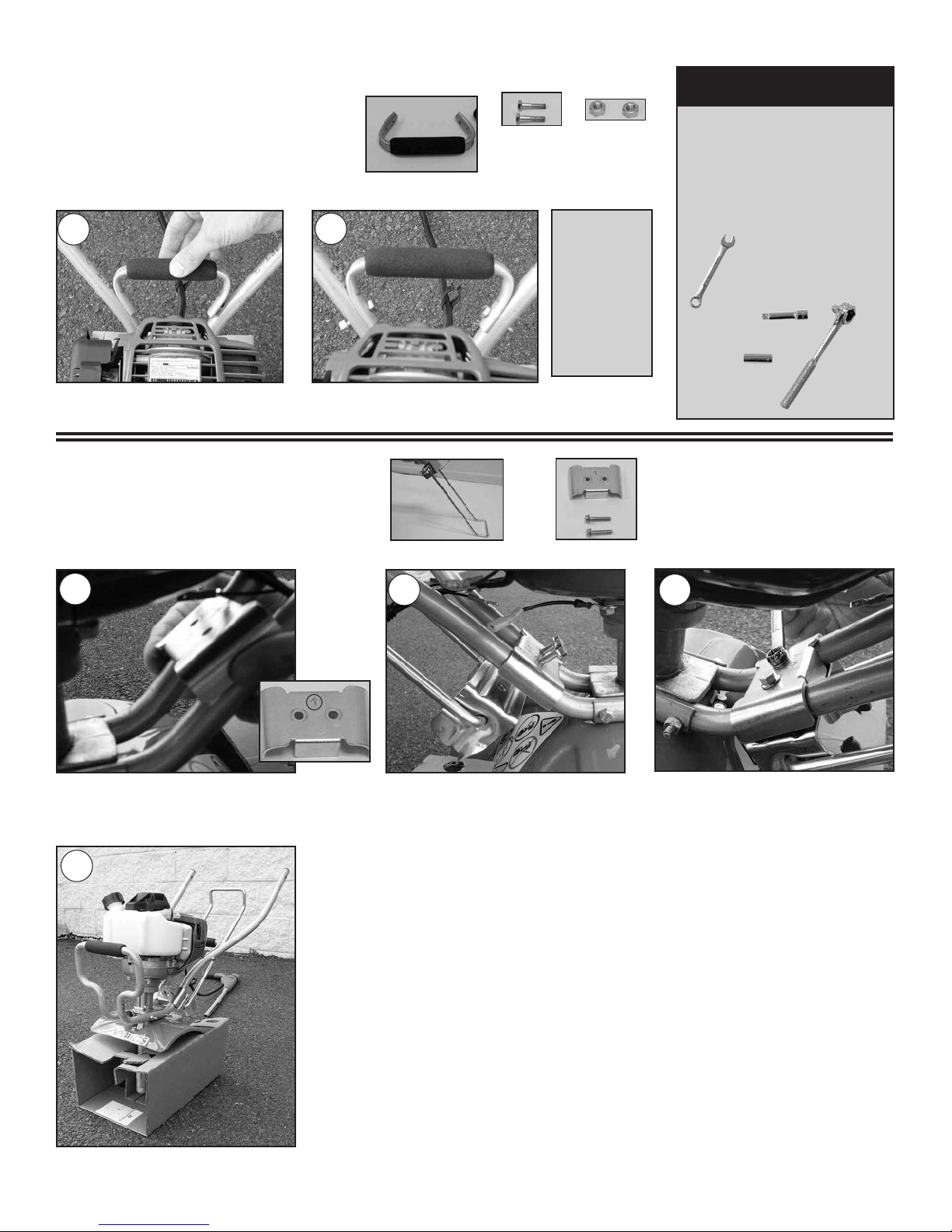
Carry Handle Assembly
ASSEMBLY (continued)
Step 5
Place Carry Handle (I) on lower
handle bars and line up holes for bolts.
Place (2) 1-1/8” bolts (J) through holes and
finger tighten. 1/4-20 two-way lock nuts (H).
Hex head cap
screws go on
the inside and
nuts go on the
outside.
Helpful
Hint
Use tools and tighten all
fasteners of the lower
portion of the tiller.
(Steps 1 thru 5)
Kickstand Assembly
Step 6
Place kickstand brace on top
portion of lower handle with the
stamped arrow pointing up.
Fully assembled lower portion of the tiller.
Place kickstand below lower handle
so the holes of the kickstand line
up with the kickstand brace (Z).
Place (2) 1/4-20 serrated flange
screws (Za) through the holes in
the top brace and tread into
kickstand (Y).
Tighten kickstand (Y) and
kickstand brace (Z) with (2) 1/4-20
serrated flange screws (Za) using
3/8” wrench.
Ratchet
7/16” Wrench
Extension
7/16”
Socket
Parts Needed:
Parts Needed:
I – Carry Handle w/grip
J – 1/4-20 x
1-1/8 Hex head
cap screws
H – 1/4-20
Two-way
lock nut
L
Z – Kickstand Brace Kit
Y – Kickstand
5A
6A
6B
6C
6D
5B
IMPORTANT
 Loading...