

Page 1

LITTLE
OWNER'SMANUALandSAFETYINSTRUCTIONS
i_I i _ _ i _ _ _ i _ _ i _ i i _ii_
Single Edged (Models 19!0, 2410,3010, 1912,2412, 30!2)
_nd Double Edged (Models !920, 2420, 3020, 1922, 2422, 3022)
Electric HedgeTrimmers
(_ MANUELDEL'UTILISATEURINSTRUCTIONSDE
et
SECURITE
tranchant unique (modUles 1910, 2410, 3010, 1912, 2412 et 3012)
et _ double tranchant (modUles 1920, 2420, 3020, 1922, 2422 et 3022)
Taille-haies _lectriques
MANUALDELPROPIETARIOe INSTRUCCIONESDE
SEGURIDAD
para las unidades con una sola cuchilla (modelos 1910, 2410, 30!0, 1912, 2412, 3012)
y las unidades con dos cuchillas (moddos 1920, 2420, 3020, 1922, 2422, 3022)
Podadora de arbustos dOctrica
WARNING DANGER
BLADES ARE EXTREMELY SHARP.
TO AVOID INJURY WHEN UNPACKING
THE HEDGE TRIMMER,
DO NOT GRASP THE BLADES.
AA TrSSEMEN ANCER
LES LAMES SONT EXTREMEMENT
COUPANTES. POUR EVITER DE SE BLESSER
PENDANT LE DEBALLAGE DE L!APPAREIL,
NE PAS LE SAISIR PAR LA LAME.
_ AD VERTENCrA I'ELIGRO
LAS CUCHILLAS ESTAN
EXTREMADAMENTE F!LosAs: PARA
EVITARSE UNA LESION AL DESEMPACAR
LA PODADORA DE ARBUSTOS, NO LA
SOSTENGA POR LAS CUCHILLAS.
Page 2
TABLE OF CONTENTS
Page
I. IMPORTANT INFORMATION
A. Introduction ....................................................................................................... 2
II. GENERAL SAFETY RULES ........................................................................................... 3
A. Safety Decals ...................................................................................................... 4
B. Safety Symbols Identification ........................................................................... 4
C. Special Safety Rules .......................................................................................... 5
D. Warnings -- Dont's ............................................................................................ 5
E. Warnings -- Do's ................................................................................................ 5
Ill. UNPACKING AND ASSEMBLY INSTRU(;TIONS ............................................................. 6
IV. OPERATfON
A. Instructions for Proper Operation ................................................................ 6-7
_. MAINTENANCE
A. Lubrication ......................................................................................................... 7
B. Service Maintenance Guide .............................................................................. 7
VI. SERVICE
A. Trouble Shooting ............................................................................................... 8
B. Blade Adjustment ............................................................................................... 8
VII. PARTS EXPLOSIONS ............................................................................................ 9-13
VII. SPECIFICATIONS .................................................................................... BACK COVER
LIMITED SERVICE O) WARRANTY POLICY ....................................................... Back Cover
L IMPORTANT INFORMATION
A. INTRODUCTION
This manual provides the information
On behalf of everyone at Little _onder, we
would like to thank you for your purchase of a
Little Wonaer Electric Powered Hedge
Trimmer. This professional trimming machine
was designed to the highest standards to ensure
necessary for safe and efficient operation and
service. For your safety, it is critically
important that you read and understand this
entire manual before operating your hedge
trimmer.
you many hours of uninterrupted service.
Page 3

IL GENERAL SAFETY RULES
Warl1111g: When using electric tools, basic safety
precautions, including the following, should always be
followed to reduce the risk of fire, electric shock and
personal injury.
Read all these instructions before operating this
product and save these instructions.
For safe operations:
1__ Keep work area clean.
Cluttered areas and benches invite injuries.
2__ Consider work area environment.
Do not expose power tools to rain. Do not use
power tools in damp or wet locations. Keep work
area well lit. Do not use power tools where there
is risk of fire or explosion.
3__ Guard against electric shock.
Avoid body contact with earthed or grounded
surfaces e.g. pipes, radiators, ranges, refrigerators.
4__ Keep children away.
Do not let visitors touch the tool or extension
cord. All visitors should be kept away from area.
5__ Store idle tools.
When not in use, tools should be stored in a dry,
high or locked up place, out of reach of children.
6__ Do not force the tool.
It will do the job better and safer at the rate for
which it was intended.
7__ Use the right tool.
Do not force small tools or attachments to do the
job of a heavy duty tool. Do not use tools for
purposes not intended; for example, do not use
circular saws to cut tree limbs or logs.
8__ Dress properly.
Do not wear loose clothing or jewelry, the can be
caught in moving parts. Rubber gloves and non-
skid footwear are recommended when working
outdoors. Wear protective hair covering to contain
long hair.
9__ Use safety glasses.
Use face or dust mask if the cutting operation is
dusty.
10) Do not abuse the cord.
Never carry the tool by the cord or yank it to
disconnect if from the socket. Keep the cord away
from heat, oil and sharp edges.
1_] Secure work.
Use a vice to clamp the frame bar while adjusting
blades. It is safer than using your hand and it frees
both hands to operate the tools.
12) Do not overreach.
Keep proper footing and balance at all tinres.
13) Maintain tool with care.
Keep cutting tools shalt_ and clean for better and
safer performance. Follow instructions for
lubrication and changing accessories. Inspect tool
cord periodically and if damaged have it repaired
by an authorized service facility. Inspect extension
cords periodically and replace, if damaged. Keep
handles dry, clean and free front oil and grease.
14) Disconnect tools.
When not in use, before servicing and when
changing accessories such as blades, bits and
cutters.
15) Remove adjusting keys and wrenches.
Form the habit of checking to see that keys and
adjusting wrenches are removed front the tool
before turning it on.
16) Avoid unintentional starting_
Do not carry a plugged in tool with a finger on the
switch. Ensure switch is off when plugging in.
17) Use outdoor extension leads.
When tool is used outdoors, use only extension
cords intended for outdoor use.
18) Stay alert.
Watch what you are doing. Use comnaon sense.
Do not operate tool when you are tired.
19) Check damaged parts.
Before further use of the tool, a guard or other part
that is damaged should be carefully checked to
determine that it will operated properly and
perform its intended function. Check for
alignment of moving parts, free running of moving
parts, breakage of parts, mounting and any other
conditions that may affect its operation. A guard
or other part that is damaged should be properly
repaired or replaced by an authorized service
center unless otherwise indicated in this
instruction manual. Have defective switches
replaced by an authorized service facility. Do not
use the tool if the switch does not turn it on and
off.
20) Warning._
The use of any accessory or attachment, other
than those recommended in this instruction
manual, may present a risk of personal injury.
21) Have your tool repaired by a qualified person.
This electric tool conforms to relevant safety
requirements. Repairs should only be carried out
by qualified persons using original spare parts,
otherwise this nray result in considerable danger
to the user.
Page 4
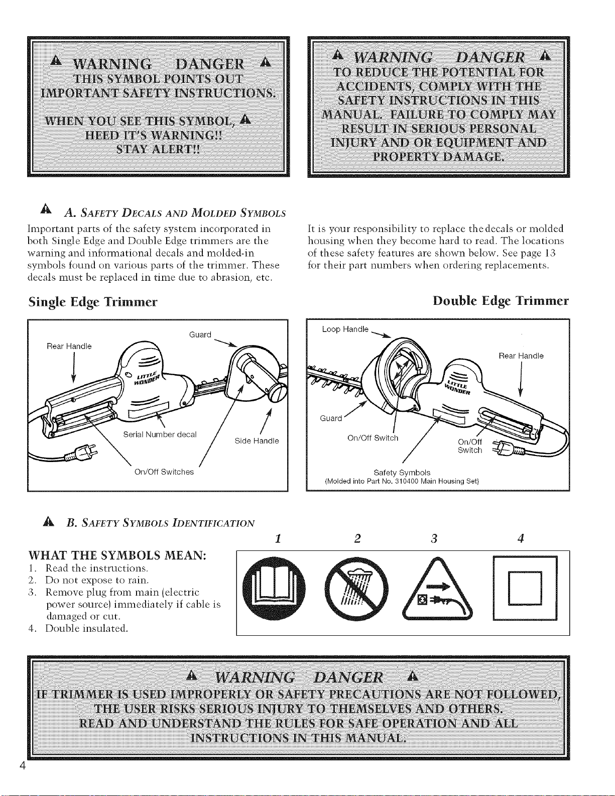
A A. SAFETY DECALS AND MOLDED SYMBOLS
Important parts of the safety system incorporated in
both Single Edge and Double Edge trimmers are the
warning and informational decals and molded-in
symbols found on various parts of the trimmer. These
decals must be replaced in time due to abrasion, etc.
Single Edge Trimmer
Guard
Rear Handle
/
Side Handle
On/Off Switches
It is your responsibility to replace thedecals or molded
housing when they become hard to read. The locations
of these safety features are shown below. See page 13
for their part numbers when ordering replacements.
Double Edge Trimmer
I
Loop Handle
Rear Handle
Guard
On/Off Switch On/Off
Switch
Safety Symbols
(Molded into Part No. 310400 Main Housing Set}
B. SAFETY SYMBOLS IDENTIFICATION
WHAT THE SYMBOLS MEAN:
1. Read the instructions.
2. Do not expose to rain.
3. Remove plug from main (electric
power source) immediately if cable is
damaged or cut.
4. Double insulated.
3 4
Page 5

A C. SPECIAL SAFETY RULES
1. Read and understand the owner's manual. Pay
particular attention to all sections regarding safety.
BE AWARE!! The blades coast after triggers are
released or motor is switched off. Make sure blades
have conle to a complete stop before letting go of a
handle.
.
Always keep a firna grip on both handles while the
blades are moving and/or the motor is running. On
Single Edged units, the right hand grasps the front
side handle and the left hand grasps the rear handle.
On Double Edged units, one hand grasps the front
'loop' handle, while the other hand grasps the rear
handle.
D. WARNINGS -- DON'TS
Don't use trimmer with one hand, keep both hands on
handles with fingers and thumbs encircling the handles,
while blades are moving, and motor is running.
Don't overreach or stand on unstable support. Do not
stand on the top of a ladder while trimming. Use proper
equipment for reaching higher heights. Keep a good
footing at all times.
Don't ever grasp cutting blades for any reason.
Don't attempt to clear cut material while blades are
moving, and the motor is running. Never try to remove
.
Maintain a firm footing and good balance; do not
overreach while trimming. Before you start to trim,
check the work area for obstacles that might cause
you to lose your footing, balance or control of the
machine.
4. Keep area clear of children, pets, and bystanders.
jammed material before switching the motor off and
making sure the blades have stopped completely.
Don't over-ride safety features.
Don't allow children or incapable people to operate this
trimmer.
Don't operate this hedge trimmer while under the
influence of alcohol or drugs.
Don't attempt to repair this hedge trimmer. Have
repairs made by a qualified dealer or repairman. See
that only original £ittle Wonder parts are used.
E. WARNINGS -- Do's
Always read and follow all instructions.
Always stay alert. Watch what you are doing and use
common sense. Do not operate unit when fatigued.
Always dress properly. Do not wear loose clothing or
jewelry, they might get caught in moving parts. Use
sturdy proper fitting, non-slip gloves. Gloves reduce the
transmission of vibration to your hands. Prolonged
exposure to vibration can cause numbness and other
ailments. Wear non-skid foot wear to ensure secure and
proper footing.
Always wear ear and eye protection. Eye protection
must meet ANSI Z 87.1. To avoid hearing damage we
recommend hearing protection be worn whenever using
the eqtfipment.
Always keep both hands on both handles when
trimmer is running. Severe injuries can result if you
try to use the hedge trimmer with only one hand or
with an insecure grip.
Always keep children, pets, and incapable persons
away.
Always use trimmer properly. Cut only types and size
of growth described in the Trimming section of this
manual. Overloading or abusing your hedge trimmer
can cause premature failure and can result in injury.
Use conlnlon sense.
Always keep a safe distance between two or more
operators when working together sinmltaneously.
Always inspect your unit before each use and ensure
that all handles, guards, safety devices and fasteners are
secure, operating, and in place.
Always maintain and examine your trimmer with care.
Follow maintenance instructions given in manual.
Always store trimmer in a sheltered area (a dry place)
not accessible to children. The hedge trimmer should
not be stored in a house.
Page 6

Ill. UNPACKING AND ASSEMBLY INSTRUCTIONS
A WARNING DANGER
BLADES ARE EXTREMELY SHARE TO
AVOID INJURY WHEN UNPACKING THE
HEDGE TRIMMER, DO NOT GRASP THE
BLADES.
Your Lit.tl_ H!ond_r hedge trimmer has been
assembled for you at the factory. Before operating be
IV. OPERATION
A. INSTRUCTIONS FOR PROPER OPERATION
sure all fasteners are secure, and all guards and safety
devices are in place and operating properly.
Securing the
extension cord.
Bend the extension
cord about 6" from
the plug end. Push
that bend through
the oblong opening
in the back of the
handle. Then loop
the bend under the
cord retaining clips
as shown. This will
prevent the extension
cord from detaching
from the hedge
trimmer plug.
66
Misuse of this Hedge Trimmer will void the warranty.
ie: cutting hedges or shrubs over 1/2" in diameter or
foreign objects such as wires, rocks, or fences. Before
trimming check work area for foreign objects such as
wires, cords, glass, fences, or rocks. Be sure to remove
any foreign objects from the work area. Failure to
properly maintain this hedge trimmer will void the
8
warranty.
Page 7

Read care and safety instructions carefully before
attempting to use this trimmer. Only after you are
familiar with your hedge trimmer and all of its controls
and the functions should you start the trimmer.
Before plugging into an electric circuit, be sure that the
voltage supply is as specified on hedge trimmer.
Models 1910, 1920, 2410, 2420, 3010, 3020 are rated at
464 watts at 115 volt,s.
Models 1912, 1922, 2412, 2422, 3012, 3022 are rated at
390 watts at 230 volts.
Be sure the switches are in the "off" {not depressed}
position before connecting unit to the applicable
current. (120V AC or 220V/240V AC.} Do not carry a
plugged -in trimmer with a finger on the switch.
The electricity for this hedge trimmer should be
supplied through a Residual Current Device (RCD} with
a tripping current of not more than 30 mA. These
protective devices are also known as Residual Current
Circuit Breakers (RCCBs} or Earth Leakage Circuit
Breakers (ELCBs}.
5. Keep extension cord behind trimmer. Never drape
V. MAINTENANCE
extension cord over hedge being trimmed. On 120V
units, use 16 gauge wire extension cord up to 100 feet.
Over 100 feet use 14 or heavier gauge wire or extension
cord. Cords are available from your local Little Wonder
dealer. The use of light gauge lamp cords or sizes lighter
than those specified above will result in loss of power,
possible motor failure, overheating of cord and the
possibility of fire.
6.
Warning! These trimmers have been designed so they
can only be operated when using both hands. Do not
attempt to override this important safety feature in any
way.
7.
Hold trimmer firmly. For Single Edge Model, keep right
hand on side handle and left hand on rear handle. For
Double Edge Model, you can place either hand on either
handle. Squeeze both switches.
Tilt trimmer so cutting tooth is angled slightly toward
the hedge or shrub and proceed to cut. Use
overlapping sweeping motions away from your body to
achieve a safe and even cut. The unit is designed
to cut any type of hedge or shrub; however, _'_
thickness of cut should not exceed 1/2 inch { 1/2" )
in diameter.
Remove the plug from the socket before carrying out any adjustment, servicing, or maintainence.
A. LUBRICATION AND MAINTENANCE
.
.
A few drops of light (#10) oil should be placed on
the back edge of each blade at each adjusting
screw after approximately every four hours of
normal operation.
.
To obtain trouble free trimming, it is necessary to
keep the blades lubricated and clean. The gum
that collects and builds up on the blades can be
removed with 50-50 mixture of kerosene and #10
oil. Since a petrolenm product can shorten the life
of sonic plastics, it is necessary to remove excess
oil-kerosene mixture from the plastic parts. Blades
n]ust be clean before they can be adjusted.
Caution! Kerosene and oil are flammable,
.
A few drops of light (#10) or 3-in-1 oil should be
put in the hole indicated on the bottom cover
plate. This is necessary only at the beginning of a
day's operation.
B. SERVICE MAINTENANCE GUIDE
Gear housing and motor bearings have been
permanently lubricated with a special grease
which should last for the life of the trimmer. When
blades are replaced, or any other time that the
bottom cover plate is removed, the grease n]ust be
checked for proper anrount (approximately 3/4 full
in the area of the gears), and a new gasket and new
screws nmst be used to insure proper seating of
cover plate. Use only Lubrico M3-3K9K grease
(P/N 16-78A) in the gear housing. Lubrico M24M
(P/N 16-78B) is to be used on the motor bearings.
Lubrico is available through your local Little
Wonder Dealer.
S.
Before each use, inspect to be sure handles, safety
devices and fasteners are secure and in place, and
cord is not frayed. If the supply cord is damaged, it
nmst be replaced by the manufacturer, its service
agent or similarly qualified person in order to
avoid a hazard.
Area Maintenance Frequency
Gear Housing Check Grease Monthly
Blades Inspect / Clean / Lubricate After Each Use
Fasteners Inspect / Tighten / Replace Before Each Use
Labels Inspect / Replace Before Each Use
Handles Inspect / Replace Before Each Use
Guards / Safety Devices Inspect / Replace Before Each Use
IMPORTANT- Time intervals shown are nlaxinlunl. Actual use and your experience will determine the
frequency of required maintenance. 7
Page 8

VL SERVICE
A. TROUBLE SHOOTING
Problem
1. Blades don't cut cleanly.
2. Blades don't move when
turned on.
3. Excessive electrical arcing
from vents in top of
trimmer.
B. BLADE ADIUSTMENT
The care and adjustment of the blades is very important
to the efficient operation of the trimmer and especially
to the long life of the motor.
Make sure the trimmer is NOT plugged in.
1. Turn trimmer upside down. Place trimmer in vice,
clamping on the sides of flame bar. Be careful!
Blades are sharp!
2. Using a 7/16" wrench, loosen all blade locknuts
and unscrew the large head screws by two turns.
Blades are dull or not adjusted
properly.
Blades are adjusted too tight.
Worn brushes.
Cause
Have blades sharpened and
adjusted.
Re-adjust blades following
service instructions.
Replace brushes - follow
service instructions.
Single Edged trimmer or the protective comb of the
Double Edged trimmer can just be moved with
finger pressure. (A .001S" (1 1/2 thou.)feeler gauge
just slips under the blade guard or comb when
properly adjusted.) Tighten the locknuts while
holding the screw stationary in its correct adjusted
position. Re-check to make sure the blade guard or
conlb can still be moved.
4. Repeat Step 3 on each screw in turn until all are
correctly adjusted.
Remedy
3. Starting with the screw nearest the gear housing,
tighten the screw until the blade guard of the
SINGLE EDGED
NOTE: CORRECT BLADE ADJUSTMENT CAN
ONLY BE ACHIEVED ON CLEAN, OILED BLADES.
DOUBLE EDGED
Page 9

Single Edge Assembly
iNSTALL WIRES FROM
THROUGH WIRE TROUGH
KEY
PART #
1
310100
2
16-54B
2
16-54B
2
16-54B
3
310106
4
NA
5
310310
5
310305
5
310300
6
30-2
6
24-2
6
19-2
7
30-1
7
24-1
7
19-1
8
310215
9
16-93
9
16-93
9
16-93
10
16-54A
10
16-54A
10
16-54A
11
3036-B
12
310505
DESCRIPTION
Gear Housing Assembly {including pressed in pins /
Nut Lock 1/4-28 whiz Flange (for models 3010, 3012 / 30" SE
INut Lock 1/4-28 whiz Flange (for models 2410 2412} 24" SE
Nut Lock 1/4-28 whiz Flange (for models 1910, 1912} 19" SE
Frame Bar Support
Side Handle Assembly {See individual part numbers)
IFrameBar a_semblv(fnr mndel_,_010 30191,:_(1" SF
Frame Bar assembly {for models 2410, 2412} 24" SE
Frame Bar assembly (for models 1910, 1912) 19" SE
Inside Blade (for models _010, _012! 30" SE
Inside Blade {for models 2410, 2412} 24" SE
1lnside Blade ifor models 1910. 1917.1 19" SE
iOutside Blade (for models 3010. 3012} 30" SE
Outside Blade (for models 2410, 24121 24" SE
Outside Blade {for models 1910, 1912) 19" SE
Conduit
Blade Guard (for models 3010_ 3012} 30" SE
Blade Guard (for models 2410, 2412 / 24" SE
IBlade Guard (for models 1910, 19121 19" SE
ILarge Head Phillips Screw {for models 3010, 3012) 30" SE
ILarge Head Phillips Screw (for models 2410, 2412 / 24" SE
iLarge Head Phillips Screw (for models 1910_ 1912) 19" SE
1/4-9.8 Flange Locknut
Screw, 1/4-28 x 1" Large Head
QTY.
1
7
6
5
1
1
1
1
1
1
1
1
1
1
1
1
5
4
3
4
3
2
3
1
Page 10

Double Edge Assembly
KEY #
1
2
2
2
3
4
5
5
5
6
6
6
7
7
7
8
8
8
9
9
9
10
11
PART #
310100
16-54B
16-54B
16-54B
300300
NA
310325
310320
310315
30-2D
24-2D
19-2D
30-1D
24-1D
19-1D
30-42
24-42
19-42
16-54A
16-54A
16-54A
310500
310505
& ®
DES CRIPTION
Gear Housing Assembly iincludin_ pressed in pins}
Nut Lock 1/4-28 whiz Flange {for models 3020_ 3022) 30" DE
Nut Lock 1/4-28 whiz Flange ifor models 2420, 24221 24" DE
Nut Lock 1/4-28 whiz Flange {for models 1920, 1922} 19" DE
Frame Bar Support
Loop Handle Assembly (See individual part numbers}
Frame Bar assembly (for models 3020. 30221 30" DE
Frame Bar assembly (for models 2420, 2422} 24" DE
Frame Bar assembl¥ (for models 1920, 1922} 19" DE
Inside Blade (for models 30201 3022)30" DE
Inside Blade (for models 2420, 2422} 24" DE
Inside Blade {for models 1920, 19221 19" DE
Outside Blade (for models 3020, 30221 30" DE
Outside Blade (for models 2420, 2422} 24" DE
Outside Blade {for models 1920, 1922} 19" DE
30" Comb {for models 3020, 3022} 30" DE
24" Comb (for models ....'94'90_'9429). 24" DE
19" Comb {for models 1920, 1922) 19" DE
Large Head Phillil_s Screw {for models 3020. 30221 30" DE
Lar,_e Head Phillips Screw (for models 2420, 24221 24" DE
Large Head Phillips Screw {for models 1920, 1922} 19" DE
Screw_ Plas-Tite #8 x 3/4"
Screw, 1/4-28 x 1" Large Head
QTY.
1
7
6
5
1
1
1
1
1
1
1
1
1
1
1
1
1
1
4
3
2
2
1
10
Page 11

Gear/Motor Assembly
t
%
\
<
KEY # PART #
1 310100
2 16-57A
3 310407
4 D16-71
5 16-62
6 D16-59
7 16-64
8 16-65
9 16-67
10 16-81-1
11 310503
12 3042
13 D16-56F
14 310903
14 310900
15 310108
17 16-69D
18 310901
18 310902
19 16-69E
20 3025
21 310105
22 3026
DESCRIPTION QTY.
Gear Housing Assembly 1
Gear Housing Cover Plate 1
Grommet Rubber 4
Gasket Cover Plate 1
Eccentric Gear 1
Cluster Gear 1
Connectin _ Rod 1
Spacer Connecting Rod 1
Felt 1
Screw 6-32 x 5/16 8
Motor Bolt 8-32 x 2 1/2 2
M_¢Jo,i_ ¢ $¢j;¢w 4
Wear Plate 1
Stator 120V {For Models 3020, 3010, 2420, 2410, 1920, 1910} 1
Stator 230V {For Models 3022, 3012, 2422, 2412, 1922, 1912} 1
Motor Housing Base and Cap Set with Brush Holder 1
Bearing Lower 1
Armature 120V (For Models 3020 r 3010 r 2420, 2410, 1920_ 1910) 1
Armature 230V (For Models 3022. 3012. 2422. 2412. 1922. 1912} 1
Bearing Upper 1
Brush Holder (not shown) 2
Brush 2
Brush Retaining Plate 2
11
Page 12

Double Edge Front Loop Handle Assembly NORMALLYCLOSED
BLACK WIRES
SET OF 13)
NORMALLY OPEN
ATTACH RED
KEY# PART#
1 3033
2 310405
3 310219
4 310203
5 310207
6 310504
7 310500
8 310218
TO PC BOARD
DESCRIPTION
Switch Normally Open
Switch Normally Closed
Loop Handle Tri_er Set
Loop Handle Set
Shield
Screw Plasti-Tite #8 x 1"
Screw Plasti-Tite #g × 3/4"
Loop Handle Trigger Strap
QTY.
1
1
1
1
i
3
2
1
Single Edge Front Handle Assembly
12
®
/
KEY #
PART#
1
310206
2
310210
3
3033
4
310405
5
310502
6
310501
7
310500
8
310200
DESCRIPTION
Side Handle Shield
Trigger Side Handle
Switch Normallv Ot3en
Switch Normally Closed
Nut Nylock 1/4-28
Socket Flat Head 1/4-28 x 3/4 ss
Screw Plasti-Tite #g x 3/4"
Side Handle Set
QTY.
1
1
1
1
1
1
3
1
Page 13

Main Housing Assembly
RED WIRES
AT[ACH BLACK WIRE
TO FRONT SWITCHES
KEY # PART #
1 310400
2 310403
3 310404
5 310438
5 310436
5 310439
5 310437
6 310209
7 3033
8 310405
9 310500
10 310504
ll 310410
11 310412
12 310600
13 310217
DESCRIPTION
Main Housing Set
Housing Brush Cap Cover Plate
Housin_ Loon Handle Cover Plate *
PC Board Assembly (for Models 3012, 2412 r 1912 /
PC Board Assembly (for Models 3010, 2410, 1910}
PC Board Assembly (for Models 3022, 2422_ 1922}
PC Retard A_emhlv (fc)r McMel_ 3090 9_t9() 19901
Trigger Rear Housing
Switch Normally Open
Switch Normally Closed
Screw_ Plasti-tite #8 x 3/4"
Screw, Plasti-tite #8 x I"
120V Cord Assembly
230V Cord Assembly
Warning Label
Grommet, Conduit * *
* Not needed for double edge models.
** Not needed for single edge models.
QTY.
1
1
1
1
1
1
1
1
1
1
6
3
1
1
1
1
13
Page 14

VIII. SPECIFICATIONS
Model
1912
Cutting Length
cm (in.)
48 (19)
Weight
kg (lb)
3.49 (7.7)
The A-weighted emission sound pressure level
at the operator position has been measured at:
L1,A= 80 dB(A). These measurements were
made in accordance with EN ISO 11201:1996
1922
2412
2422
3012
48 (19)
61 (24)
61 (24)
76(30)
3.89 (8.6)
3.62 (8.0)
4.04 (8.9)
3.85(8.5)
under no-load conditions.
The Hand-Arm weighted r.m.s, vibration
measured at the handles in accordance with
EN 50144-1 part 13.3 at rated conditions, no
3022
All listed hedge trimmers are rated for
230 volts AC at 50 hertz.
76(30)
4.59(10.1)
load was: 1.0 m/sL
LIMITED SERVICE & WARRANTY POLICY
FOR ELECTRIC HEDGE TRIMMERS
All Uttl_ H/onrl_r Electric Hedge Trimmers are _laranteed against defects in material and
workmanship for a period of 2 YEARS froln date of purchase, when used for RESIDENTIAL SERVICE, or
1 Year when used for COMMERCIAL SERVICE. Any Little Wonder Electric Hedge Trimmer or part
found to be defective within the warranty period is to be returned to any registered Little Wonder Dealer.
Transportation charges for parts and units submitted for replacement under this warranty nlust be
borne by the purchaser.
THIS WARRANTY shall not be effective if the product has been subject to misuse, negligence or
accident, used in cutting hedges or shrubs greater than 1/2" in diameter, used to cut foreign objects
such as wire, rocks, or fences, or if the product has been repaired or altered outside of our Southampton
factory or any registered Little Wonder dealer, in any respect which affects its condition or operation.
LITTLE _LINDER shall not be liable for any special indirect or consequential damages arising from
defective equipment. Any implied warranty, including merchantability of fitness for a particular
purpose, shall not extend beyond the written warranty period.
THIS WARRANTY shall only be effective if the enclosed Warranty/Registration card is properly filled
out and returned to LiL_:I_ 14'_d_r, Div. of Schiller-Pfeiffer, Inc. at time of purchase.
Sp_ cifications d_scriptions, and illustrative material in this literature al_ as accurate as known at the tim_ of publication, but ar_ stlbi_ ct to chang_ without notice
Mtmufi_ct_lrcd by:
KITTKE D/VDERo
DIVISION OF SCHILLER-PFEIFFER, INCORPORATED
1028 STREET ROAD, P.O. BOX 38
SOUTHAMPTON, PA 18966
PHONE 215-357-5110 * FAX 215-357-8045
©2003, LITTLE H/OA/DER, Division Schiller-Pfeiffer, Inc. P/N :_10700
1-03
 Loading...