

Page 1

MM700 Installation Instructions
IMPORTANT SAFETY INSTRUCTIONS - SAVE THESE INSTRUCTIONS
Please read this entire manual before you begin.
Do not unpack any contents until you verify all requirements on PAGE 4.
If you have any questions, visit our website or call (800)-897-9755.
!
WARNING!
This product contains small parts that can be
a choking hazard. Do not let children play
with any of these small parts! Keep children
away from the work area during installation.
!
CAUTION:
This product is intended to be installed by
professional installation contractors, or persons
familiar with the tools and methods required for
this installation. If you are not sure about your
ability to perform this installation, you must
contact a professional. MantelMount is not
responsible for damage or injury caused by
incorrect installation or improper use.
IMPORTANT:
MantelMount has four different adjustments
that must be made after the installation is
complete in order to operate properly.
!
CAUTION:
Do not let children operate, pull on, or hang from
MantelMount. Do not let children push
MantelMount upward to the top position - this will
cause the mount to slam against the wall due to
the upward force of the springs. Only a person
tall enough to control the mount all the way to
the top should operate MantelMount.
!
CAUTION:
Do not use this product in any way, or for any
purpose, that is not specifically described in these
instructions. MantelMount is not responsible for
damage or injury caused by incorrect installation
or improper use.
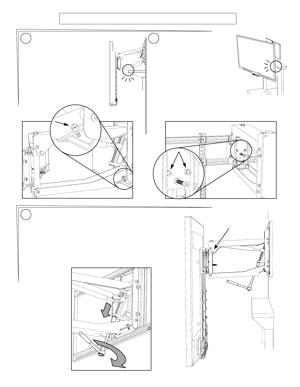
The main bolt adjusts the lifting force to
accommodate different TV weights. All TVs
within the weight range should stay in the UP
and DOWN positions when adjusted properly
The bottom travel stop is adjusted with two
screws so that the TV and mount do not
lower all the way into the mantel.
A slight amount of tilt in the UP position can
be added or removed by using one screw
inside the lifting mechanism.
The side-to-side swivel stops are adjusted
with two screws so that the TV does not
swivel into the mantel.
MantelMount MM700 PAGE 1
www.MantelMount.com
Page 2

Required Tools Optional Tools
6mm
11/64”
1
1
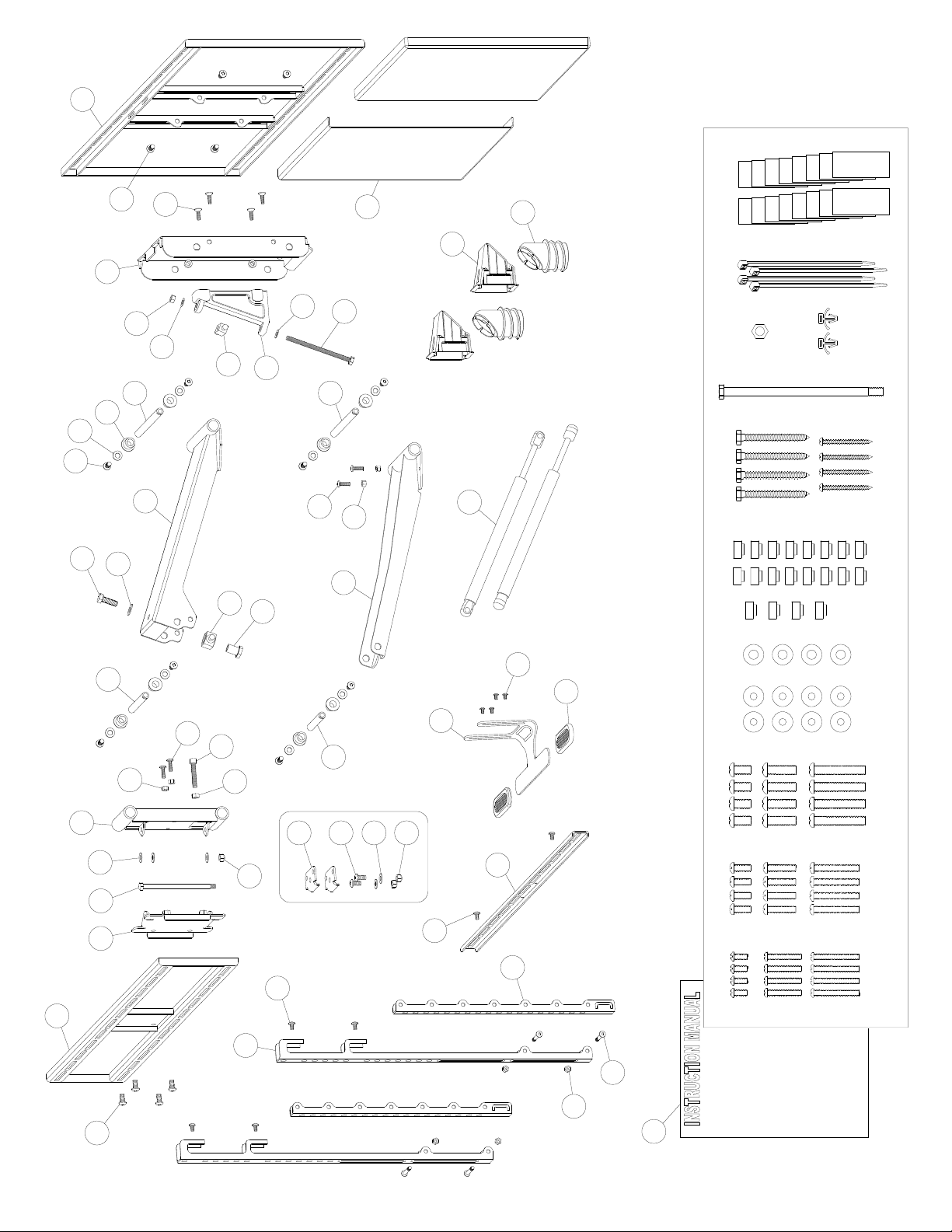
Before you begin, please verify that all components are included and undamaged. If any
parts are missing or damaged, contact MantelMount. Never proceed with missing or
damaged parts!
Lay out all components and make sure you identify that each one has a match in the
diagram. Some of the parts included will not be used during installation. Do not proceed
if you do not understand and identify all of the components.
“
2
{01} x4
M5x12
{04} x4
M6x16
{07} x4
M8x15
{02} x4
M5x30
{05} x4
M6x30
{08} x4
M8x25
{03} x4
M5x40
{06} x4
M6x40
{09} x4
M8x45
{17} x4 {19} x4
{20} x1
Safety Bolt
{10} x8
M5-M6
{11} x4
M8
{12} x4
M5-M6 Spacer
{13} x16
M8 Spacer
{21} x1
Safety Nut
{14} x8
{15} x6
{16} x4
{18} x4
{23} x8
M6
{24} x4
Cable Ties
{22} x2
PAGE 2 MantelMount MM700
{25} x8
Velcro (Hook)
Velcro (Loop)
{26} x8
Page 3

OPTIONAL:
SIDE SWIVEL KIT
{59} x2
{14} x2
{11} x2
M8 Washer
{21} x2
M8 Nut
{27} x2
Cable
Routing Box
{32} x1
Wall Plate
{35} x1
Lifting
Mechanism
{31} x2
Vertical
Brace
{30} x2
Brace
Extender
{28} x1
Center
Handle
{29} x2
Wall Cover
{33} x1
TV Brace
{34} x1
Horizontal
Brace
MantelMount MM700 PAGE 3
Page 4

Please verify that your installation meets all of these CRITICAL requirements:
MantelMount is designed for use only with decorative
fireplaces that are not the primary heat source for a
A B
house. Temperature at the front edge of mantle should
never exceed 110° F.
110°F
MAX.
Mantle must not extend from mounting surface
more than 15 inches. MantelMount can not extend past a
C
mantel larger than 15 inches. Larger mantels will also
reduce the amount of side-to-side swivel.
D
Wall must be WOOD STUD FRAME only. There must be at
least 2 studs available for mounting. Wall covering must
not exceed 5/8 inch thick.
2 STUDS
TELEVISION REQUIREMENTS:
1. Weight must be between 25 - 115 pounds.
2. Screen size larger than 44 diagonal inches.
3. Mounting screw holes are VESA compliant.
For non-VESA hole patterns, please visit:
www.mantelmount.com/non-vesa
15 inches
MAXIMUM
The space above the mantle must be taller than the TV. The required space
depends on how far out the mantle extends. Refer to chart below and add this
E
additional height to the TV height to determine if space is tall enough.
If mantle extends:
Less than 8 inches
8 - 10 inches
10 - 12 inches
12 - 14 inches
This is required space height:
TV height plus 2 inches
TV height plus 4 inches
TV height plus 5 inches
TV height plus 7 inches
larger than 44”
VESA
Width: 200-800mm
Height: 100-500mm
TV height
Space height
Mantle
Extends:
PAGE 4 MantelMount MM700
Page 5

Use a Vertical Brace {31} to determine if your television
1
is a flat back or an irregular back. An irregular back will
require spacers and longer screws to fill any spaces
between the Vertical Brace and the TV.
The Braces must be parallel to your television screen.
Choose the correct screw diameter and length for the TV.
2
Hand-thread screw combination into the TV to ensure
there is adequate thread engagement without hitting the
bottom of threaded insert. Use only minimum amount of
spacers (if required).
Flat Back Irregular Back
Irregular Back
(Recessed Threads)
Spacers
Possible Screw Combinations shown with maximum spacer
3
usage (if spacers are required).
Note: The sleeve on the Spacer always faces the Screw.
Must leave a gap
in threaded
TV insert
7-10 threads
minimum
engagement
!
CAUTION:
Do Not use screws that are too long for the threaded
inserts of Television. This can damage internal components.
IMPORTANT INFORMATION: The Vertical Braces {31} are
4
a fixed distance (1 inch) higher than the bottom of the
Wall Plate {32}. This relationship can be used to calculate
unusual mounting situations such as centering the TV in
an alcove or mounting to a specific height on the wall.
{01}
{04}
{07}
{10}
{03}
{06}
{10}
{11}
{10}
{10}
{02}
{12}
{12}
{08}
{05}
{10}
{13}
{13}
{11}
{13}
{10}
{12}
{13}
{13}
{13}
{12}
If you measure the distance from the
bottom of your TV (or Sound Bar) to the
bottom of the Vertical Braces {31} you
will automatically know the distance
from the bottom of your TV to the
bottom of the Wall Plate {32}.
You can use this information to install
the Wall Plate on the wall in order to
locate the height of your TV to any
specific height you desire.
Example: If the Vertical Braces are 6
inches higher than the bottom of your
TV, then the Wall Plate will be 5 inches
higher than the bottom of your TV when
the installation is complete.
If you are installing above a mantel,
then your installation must still have the
additional clearance for downward
motion stated in the chart in Step 9
ONE INCH
Fixed Distance
{13}
{09}
{11}
{13}
{13}
MantelMount MM700 PAGE 5
Page 6

The Vertical Braces {31} are always mounted higher than
5
the bottom of the TV. However, the Brace Extenders {30}
will be mounted one of two ways:
Without a Soundbar - The Brace Extenders are installed
within a few inches above the bottom of the TV.
With a Sound Bar - The Brace Extenders are installed
below the TV with enough room to install the Sound Bar
onto the Horizontal Brace {34}.
Vertical Braces:
Always higher
than the bottom
of the TV
Without
Soundbar:
Extenders are
1 or 2 inches
above the TV
With
Soundbar:
Extenders are
a few inches
below the TV
Insert the Brace Extenders {30} into the Vertical Braces {31}
6
and attach them both to the TV so the bottoms of the Vertical
Braces are higher than the bottom of the TV. Vertically
centered on the TV is ideal.
The bottom screws (or possibly all four screws) will pass
through both the Vertical Brace and the Brace Extenders.
3 to 12
INCHES
Attach the Extenders with Screws {18} and Nuts {23}.
7
Attach the Horizontal Brace {34} with Screws {15}.
Attach the Center Handle {28} with Screws {16}, making
sure the Handle is within one inch from the bottom of the
TV.
{23}
{18}
{15}
Measure the distance from the bottom of the Vertical
8
Braces {31} (not the Extenders) to the bottom of
television or Sound Bar (not the Center Handle).
Write down this distance to use in Step 9.
Bottom of
Vertical Brace
Bottom of TV
Bottom of
Vertical Brace
1 inch MAX (25mm)
Bottom of
{16}
Use this distance in Step 9
Sound Bar
PAGE 6 MantelMount MM700
Page 7
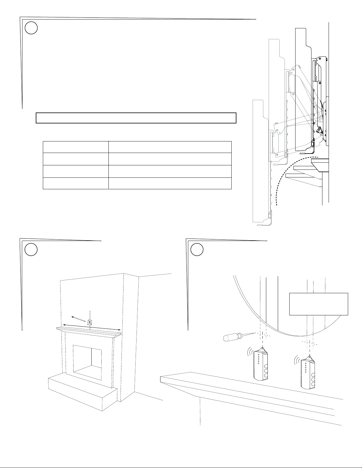
Determine the Vertical Position of the Wall Plate:
9
The image at right shows that the further out a mantle extends, it can interfere
with the arc of the lowering TV. MantelMount must be installed a minimum distance
above the mantle. This distance is additional to the distance from step 8. See the
chart below for the additional height required above the mantle. This dimension will
be used in Installation Step 12.
NOTE: If the available wall space above the mantle is close to the required space in
the table from “Requirement E” (due to the ceiling, for example) then it is
important to use the exact dimensions from this chart. However, if the available
wall space above the mantle is much taller than required, then these heights are
only minimum requirements.
USE THIS CHART FOR INSTALLATION STEP 12:
If your mantle extends:
Less than 8 inches
8 - 10 inches
10 - 12 inches
12 - 15 inches
Measure the centerline of the mantle. Mark with tape on
10
the wall.
C
L
Required Installation Height:
Add 2 inches to the distance from Step 8
Add 4 inches to the distance from Step 8
Add 5 inches to the distance from Step 8
Add 7 inches to the distance from Step 8
Locate at least two studs with a stud finder. Locate the
11
center of these studs by using a sharp awl or finish nail
poked through the drywall to locate each edge. Lag bolts
must be installed into the CENTER of the studs.
Cutout shown
for reference
MantelMount MM700 PAGE 7
Page 8
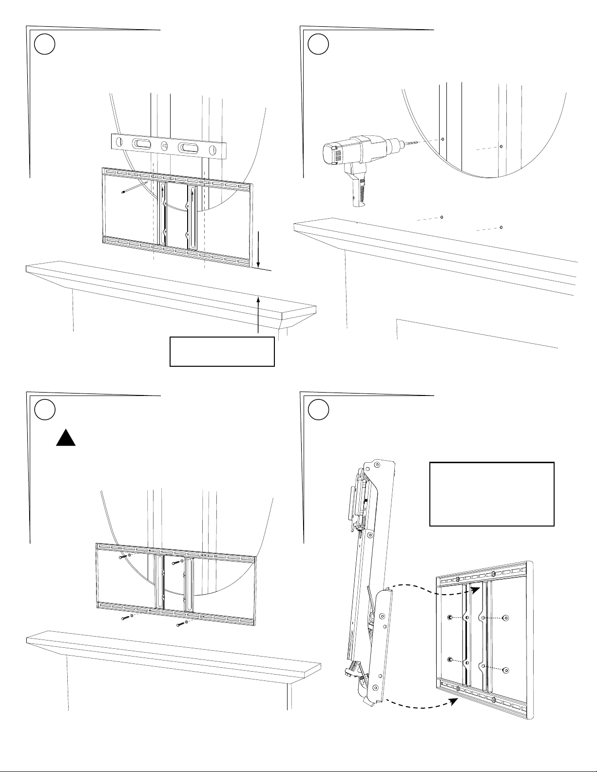
Align the arrows on the Wall Plate {32} pointing upward.
12
Center and level the plate above mantle and position the
height using the table in STEP 9. Mark the 4 spots for lag
bolts directly on center of studs.
Pre drill the 4 holes with 11/64” drill bit to a depth of
13
2.5 inches (65mm) including wall covering. Note: Wall
covering (drywall) must not exceed 5/8” thickness.
Minimum Height
from STEP 9
Attach the Wall Plate {32} using Lag Bolts {17} and
14
Washers {10} directly into the centers of the studs.
!
CAUTION:
Do Not overtighten Lag Bolts {17}. Tighten only until the
washers are firmly against the wall plate. Damage due to
overtightening can cause property damage or injury.
Insert top tabs of Lifting Mechanism {35} into the slots of
15
Wall Plate {32} then slide bottom into position. Align all
four holes and install Screws {14}. Tighten Securely.
DO NOT
damage or scratch
the rods of the
Gas Springs!
1
2
PAGE 8 MantelMount MM700
Page 9
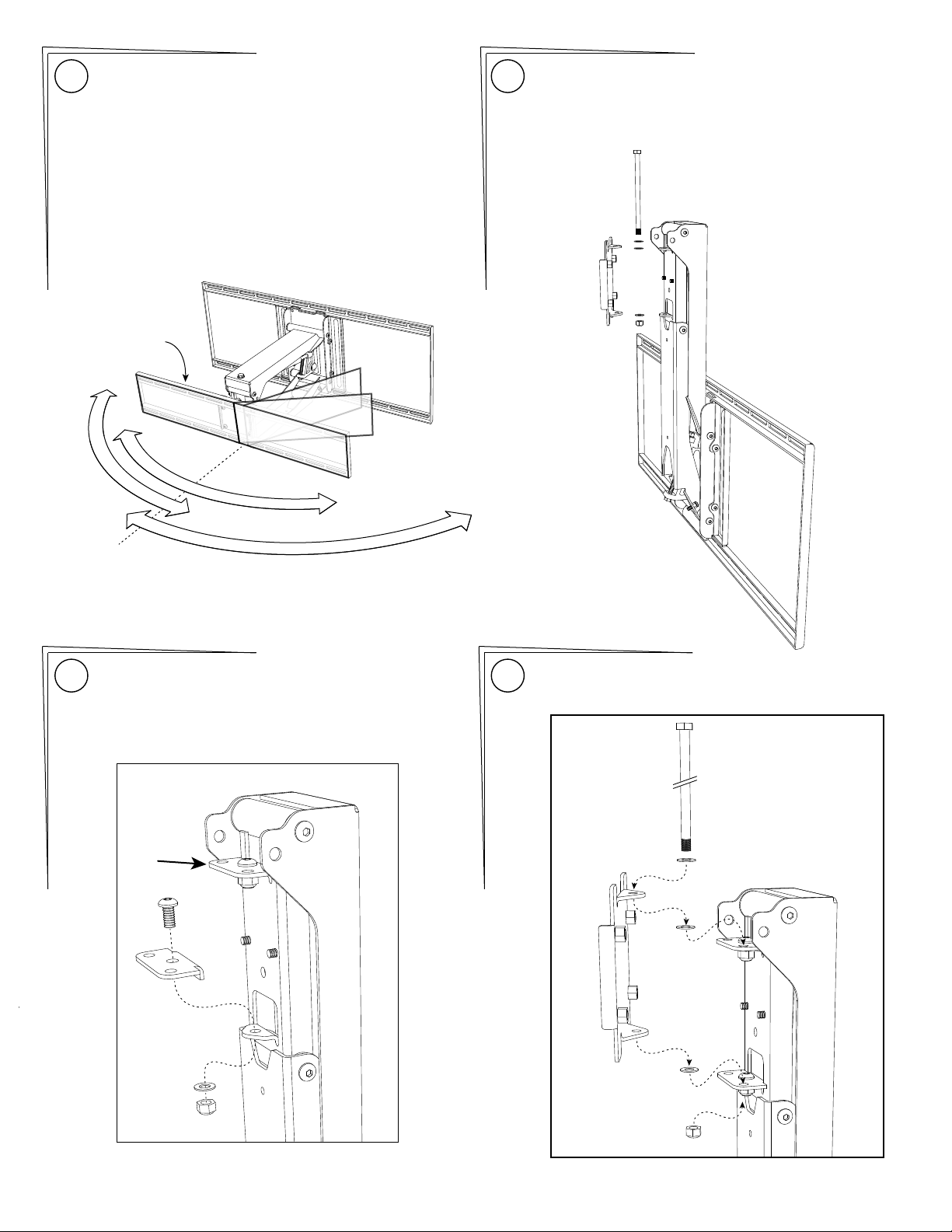
Determine the desired swivel setting: Installing the Side Swivel Kit:
16
MantelMount is designed to swivel 35° left and 35° right.
Most TVs will reach the wall within this amount of swivel.
For situations where more swivel to one side is desired,
MantelMount includes a Side Swivel Kit that will provide
60° of swivel in either the left or right direction, but not
both. This situation is only for a small TV and a mounting
situation that does not have a mantel.
If you do not need to add the Side Swivel Kit, skip ahead
to Step 20.
TV Frame
shown for
reference only
60˚
35˚
L
E
F
T
C
E
N
T
E
R
˚
5
3
6
17
Remove the Swivel TV Plate (Item 51 in the Parts List).
Save all of the hardware, it will be re-installed in the same
order it is removed.
˚
0
T
R
H
I
G
Install both Side Swivel plates onto the Lift Mechanism.
18
The plates nestle on the tops of the existing tabs of the
Swivel Bracket.
{14}
{59}
Re-attach the Swivel TV Plate onto the desired side of the
19
Side Swivel plates in the same order that each part came
off.
{11}
{21}
MantelMount MM700 PAGE 9
Page 10
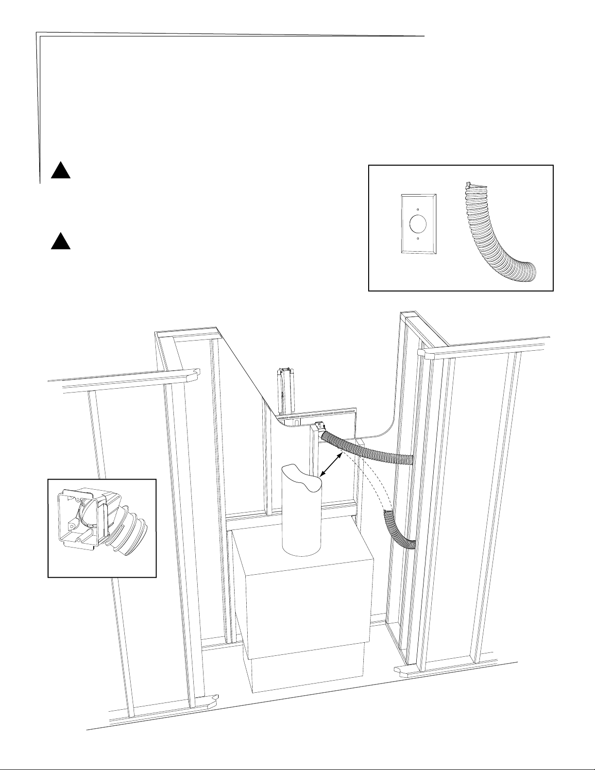
OPTIONAL Signal Cable Routing Boxes {27}: If Signal Cables have already been routed to television location, please skip
ahead to step 24. Also, if the mounting wall is an external wall, or if there is no hollow area behind mantle, please skip ahead to
step 24.
The next several steps are for the use of optional Routing Boxes {27} included with MantelMount. These boxes allow signal cables
(not power cables) to be run inside hidden metal conduit through the framed area enclosing the fireplace, in order to rout signal
cables to a side wall. See the image below for a typical installation. Any installation must comply with all local building codes.
These boxes require the purchase of metal conduit, (2 inch I/D.), long enough for the desired location. When purchasing conduit,
use the Routing Box to verify size, but do not screw it in very far because it can be difficult to remove. Conduit can be twisted or
“unwound” slightly to help position or remove the Routing Box during test-fit or installation. Both ends of the conduit must be cut
cleanly with a hacksaw before inserting the Routing Boxes.
!
WARNING
You must verify with local building codes the minimum distance that the
conduit must be located away from the fireplace components. See the
image below. Failure to obey local building codes can result in property
damage and even loss of life.
!
WARNING
Routing Boxes {27} are for signal cables only. Running power cables next
to signal cables can cause signal noise that can affect audio and video
performance. Also, your local building codes might not allow power cables
to be run through conduit. Failure to obey local building codes can result in
property damage and even loss of life.
Minimum
Distance
Parts not included:
2“ I.D.
metal
conduit
Wall plate
with large hole
Routing Box {27}
PAGE 10 MantelMount MM700
Page 11
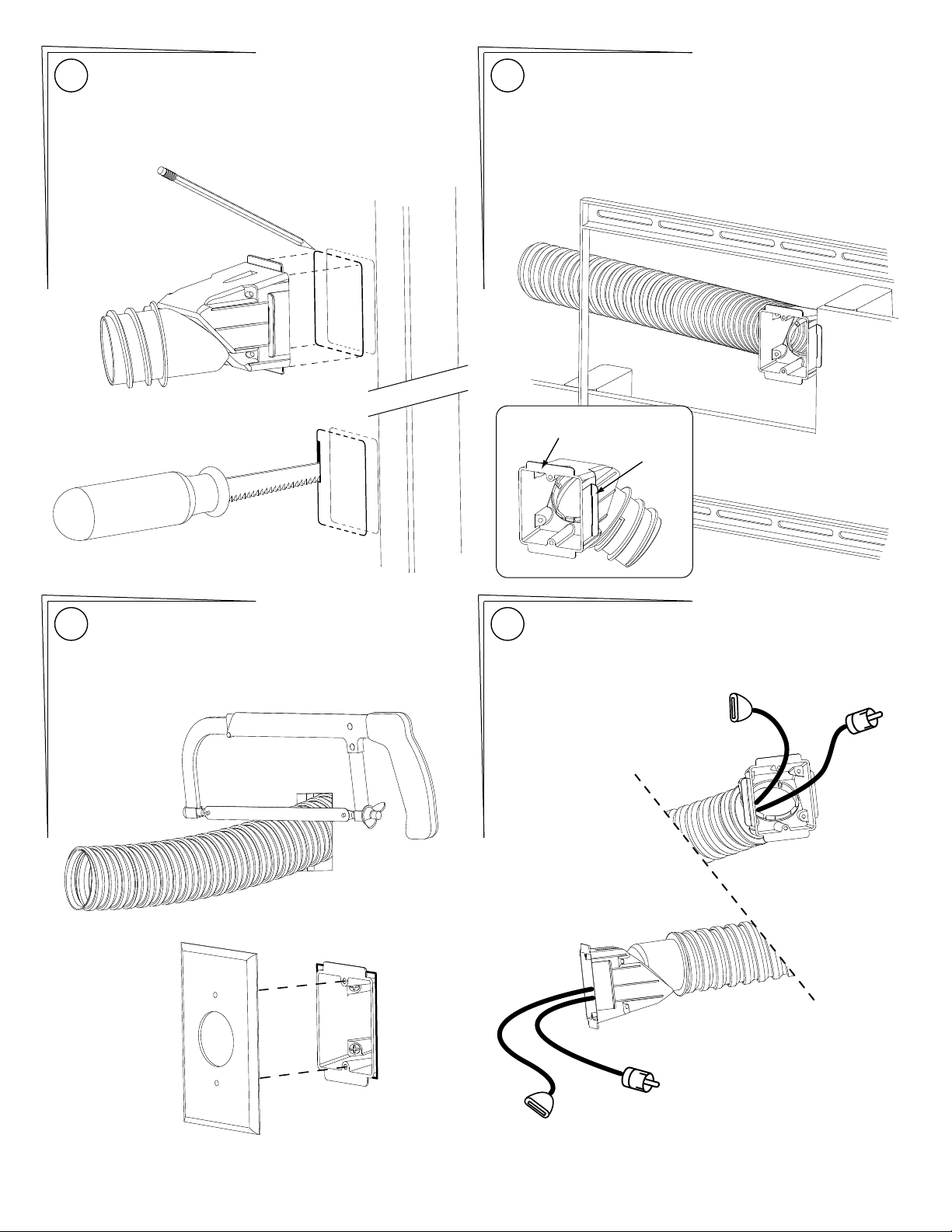
Trace the Routing Box {27} (but not the tabs) for both
20 21
desired locations onto the wall along the edge of a stud.
Boxes must be mounted to studs.
Cut out both openings through the wall covering (drywall)
along the studs using a Keyhole Saw.
STUD
Attach one end of conduit to the box and install to stud
using Screws {19}. If the box is located within the
MantelMount Wall Frame {32} as shown below, then use
the inner tabs so that the box will protrude out to the Wall
Cover {29}. If the box is located outside the area of the
Wall Frame then break off the inner tabs and mount flush
to the wall using the outer tabs.
Note: Wall cut open for clarity
Outer Tabs
Inner Tabs
Feed the conduit through the other opening and cut the
22
other end of conduit to length using a hacksaw.
Install the second box to the stud using Screws {19},
and install a cover plate if available.
Signal Cables can usually be fed through the conduit simply
23
by pushing them through from the higher opening to the
lower opening.
MantelMount MM700 PAGE 11
Page 12
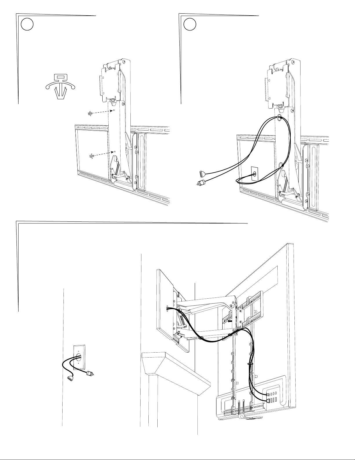
Insert the two Cable Tie Anchors {22} into the two
24
holes in the Lower Arm of the Lifting Mechanism.
Press firmly until they are flat.
{22}
Shown below is the easiest way to attach cables. Use the
25
included Cable Ties {24} to attach cables so they are
sideways to the Lower Arm, making a gentle loop.
Cables should be long enough to accommodate the
extension and swivel of MantelMount. Check all ranges of
motion before tightening the Cable Ties.
Reference Only: This is one possible configuration for the signal cables. Each segment of the cables
has extra length so that the cables are not stressed or kinked when the mount is moved.
PAGE 12 MantelMount MM700
Page 13
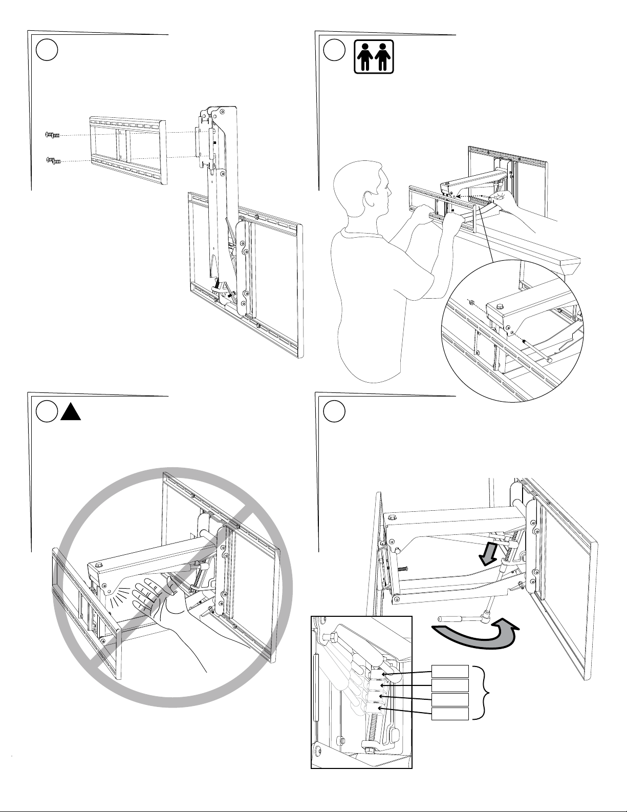
Install the TV Brace {33} to the Lifting Mechanism {35} Level the TV
26
Brace and tighten the 4 screws {14}.
27
Firmly pull down the TV Brace until the Lifting Mechanism is
in a horizontal position. DO NOT HIT THE MANTLE!
The second person must insert the Safety Bolt {20}
through the Safety Hole in the upper arm and install the
Safety Nut {21}. Slowly release the TV Brace.
Lifting Mechanism should be held at horizontal position.
THIS STEP REQUIRES TWO PEOPLE
28 29
!
WARNING:
Do Not put hands into Lifting Mechanism without the
Safety Bolt and Safety Nut installed. The power of the
Lifting Mechanism can cause bodily injury!
PRE-SET THE LIFTING FORCE:
Turn the main bolt CLOCKWISE (while looking at the head of the bolt
from underneath) as shown to pull the Gas Springs DOWN for heavy
TVs. Rotate the bolt the other way for less lifting force for lighter TVs.
See the diagram below for a Pre-Set estimate for the Gas Springs. The
lightest lifting force is at the top, and the heaviest is down just below
the middle of the bolt threads.
25 lbs
50 lbs
75 lbs
Weight of TV
100 lbs
DO NOT adjust all the way to
the bottom. That position is
only to remove the Gas Springs.
MantelMount MM700 PAGE 13
Page 14
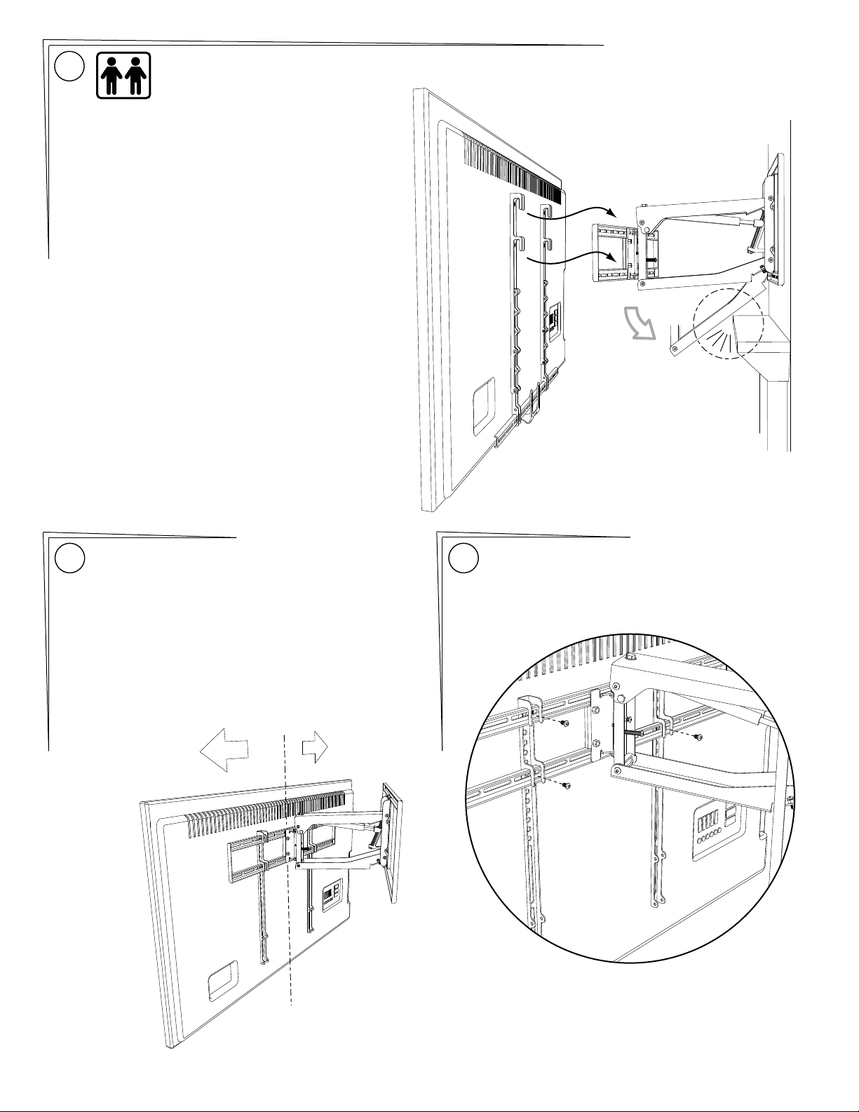
30
Carefully hang the Television onto the TV Brace
making sure that all four hooks on the Vertical
Braces {31} engage the TV Brace.
DO NOT allow the Television to drop far enough
to cause the Lifting Mechanism {35} to hit the
mantle.
MantelMount comes pre-adjusted to reduce the
possibility of contacting the mantle, but you
should always be prepared to remove the
television at this stage to make the proper
correction.
If the Lifting Mechanism {35} appears to be too
close to the mantle, remove television. Go to
STEP 33 and make an adjustment to the Bottom
Stop position. Repeat this process until the
Lifting Mechanism is a safe distance from the
mantle when the TV is installed.
THIS STEP REQUIRES TWO PEOPLE
Center the TV on the TV Frame and check it with a level.
31
Carefully slide the TV sideways, if required, until it is
balanced and horizontal, up to a MAXIMUM OF 2 INCHES
left or right.
The TV would only need to be moved off-center if it has an
unbalanced weight. These are usually older, heavier TVs.
If the TV needs to be moved sideways and is visually too
much off-center above the mantel, remove the TV and
relocate the Wall Plate {32} an equal distance but in the
opposite direction of the TV to compensate.
C
L
2 inches
2 inches
MAX
MAX
(Handle not shown)
Install 4 Screws {15} through the TV Brace {33}
32
and into the Vertical Braces {31}.
PAGE 14 MantelMount MM700
Page 15
Adjusting for Travel Stops and Television Weight:
Adjusting the Bottom Stop
33
Position:
Loosen the Locknuts and adjust
the Bottom Stop screws to the
desired stopping position.
There is one screw on each side of
the Lifting Mechanism. Make sure
to balance both sides evenly so
the TV is level in the DOWN
position.
Tighten both locknuts after the
adjustments are made.
Adjusting the Side Swivel Stop
34
Positions:
Loosen the Locknuts and adjust the
Swivel Stop screws to the desired
stopping positions, both left and
right.
Tighten both locknuts after the
adjustments are made.
Adjusting for Television weight: With Safety Bolt {20} in place,
35
use a socket wrench with an extension to adjust the long bolt inside
the Lifting Mechanism {35}. Turn the bolt clockwise (AS SHOWN
BELOW) to pull the Gas Springs down and increase the lifting force
for heavy TVs, or turn counter-clockwise for lighter TVs. This
adjustment can take several turns. (Reference Step 29.)
Adjust the bolt until the TV gently stays in the lowered position.
Move the TV up and down within the range below the Safety Bolt.
The TV should almost stay up against the Safety Bolt, but should be
easily lowered to the Bottom Stop.
Safety Bolt {20}
Safety Nut {21}
MantelMount MM700 PAGE 15
Page 16
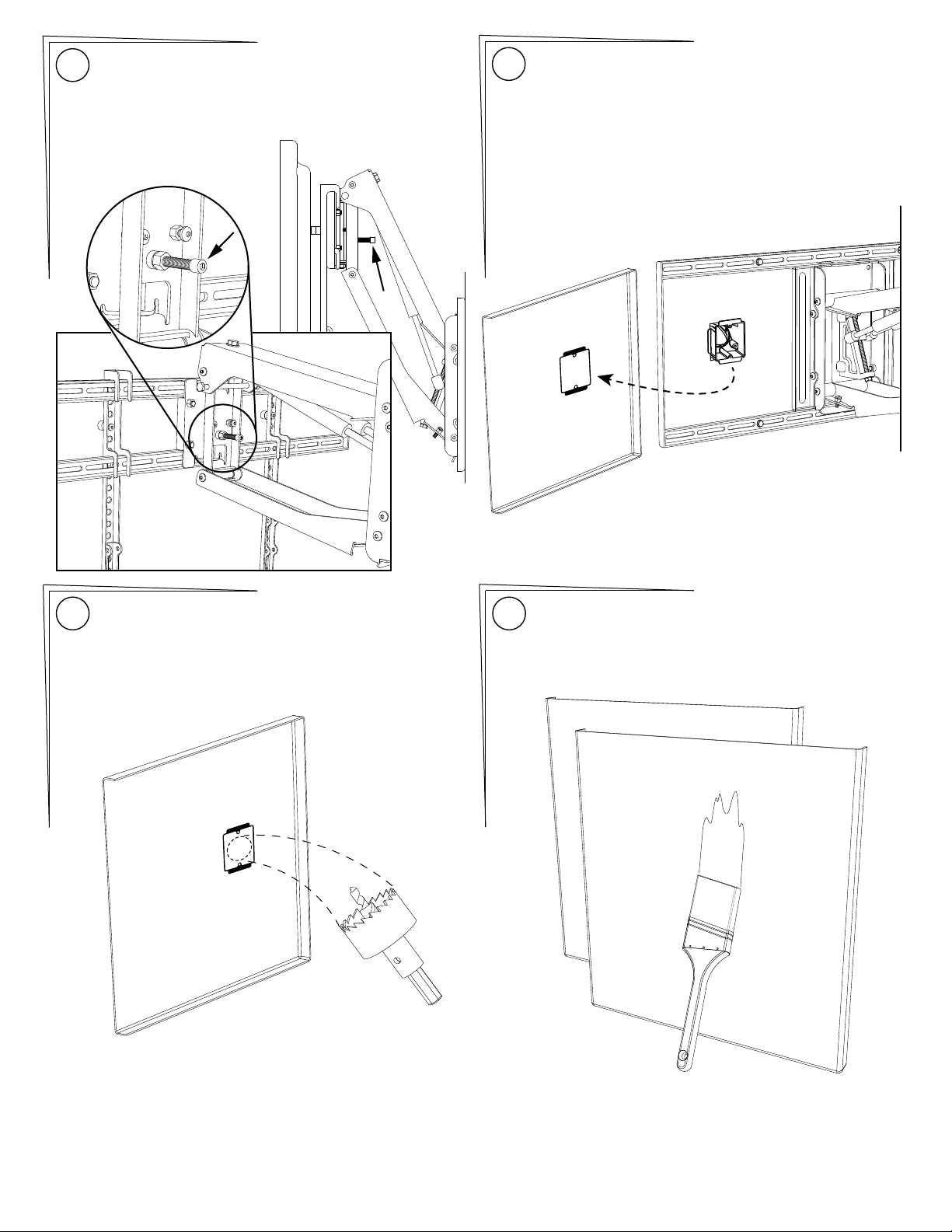
Adjusting the Vertical Tilt Position:
36
The large screw inside the Lifting Mechanism will add or
remove a small amount of vertical tilt for the TV.
The screw is backed out to stop the TV from tilting.
Do not turn the screw in more than finger snug.Tighten
Locknut when finished.
(Steps 37 and 38 only apply if the cable box was installed
37
inside the area of the Wall Frame, which will require an
access hole through the Wall Cover.)
Measure carefully OR use transfer paint (similar to lipstick)
to transfer the box location onto the Wall Cover {29}.
Use 1.5 inch Hole Saw drill bit to cut a hole through
38
the Wall Cover {29} directly in the center of the
marked area.
Be careful not to damage the edge around the hole.
Paint the Wall Covers {29} if desired.
39
PAGE 16 MantelMount MM700
Page 17
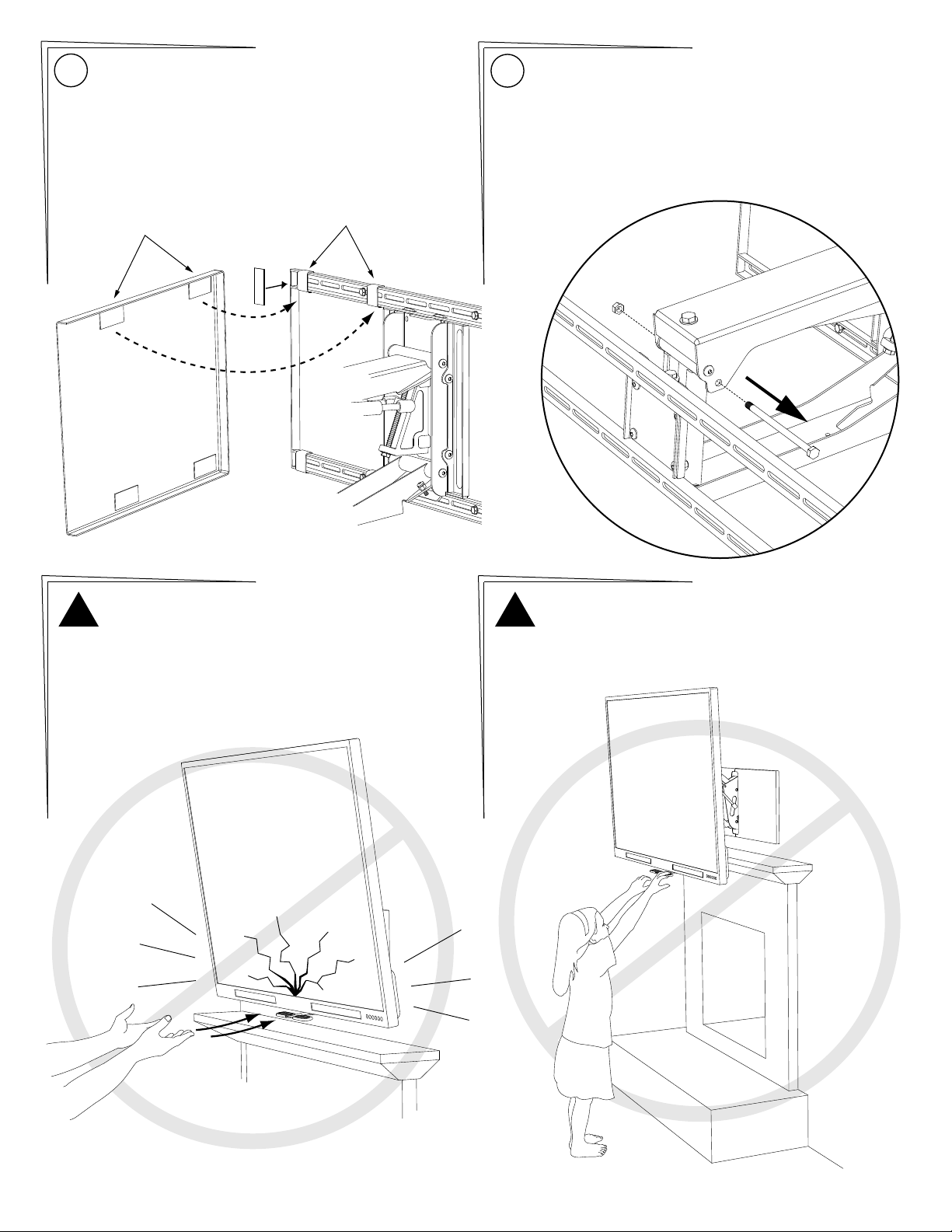
Install the Wall Covers using the included adhesive Velcro
40
strips as shown below. Apply Loop {26} pieces to the Wall
Frame, and the Hook {25} pieces to the Wall Covers.
With the television in the lowered position, remove the
41
Safety Nut {21} and Safety Bolt {20} from the Lifting
Mechanism {35}.
KEEP THIS BOLT AND NUT in a safe place for use in the
future. They are needed to remove the television or
change the Gas Springs. Recommendation: Tape them to
the inside of the Wall Cover {29}.
Hook
!
CAUTION:
Never release the handle before it is fully upright.
MantelMount is strongest in the top position, and
allowing it to slam closed can damage televisions.
Always control the lifting process.
Loop
!
CAUTION:
Never allow children to play around or operate
MantelMount. Property damage or personal injury
can occur.
MantelMount MM700 PAGE 17
Page 18
32
14
56
29
27
54
26
25
14
11
47
35
45
37
48
23
21
36
39
57
58
49
42
43
21
44
41
57
58
36
38
46
40
23
28
55
16
53
24
21
20
17
13
12
11
10
Additional Installation Parts
22
19
33
50
59
11
52
20
51
15
31
14
14
11
21
15
34
30
23
18
60
07
04
01
08
05
02
PAGE 18 MantelMount MM700
09
06
03
Page 19
Shaft 164mm
Shaft 102mm
Shaft 89mm
Upper Arm, Welded
Lower Arm
Sliding Block
Pivot Spring Mount
Pivot Spring Shaft
8
Cap Screw M8 x 5012172 1
4Flat Screw M6 x 1622
4
Disk Spring Washer
13011 1Wall Frame
13039 2TV Vertical Brace
31
32
4
4
M5 x 12
M5 x 30
13044 1TV Horizontal Brace
13029 1TV Frame
33
34
4
4
M5 x 40
M6 x 16
13064 2
13013 1Wall Bracket
35
36
4
4
M6 x 30
M6 x 40
13062 1
13059 1
37
38
4
4
M8 x 15
M8 x 25
13018 1
13020 1
39
40
4
8
M8 x 45
Washer M6
13024 1Adjustment Block
12220 1
41
42
4
17
Washer M8
Spacer M6
12257 1
13033 1
434544
16
18
Spacer M8
Round Head Screw M8 x 16
12115 Bushing
6
Round Head Screw M6 x 10
14130 1Hex Bolt M10 x 30
13066 1Hex Bolt M8 x 145
46
47
4
4
Round Head Screw M5 x 8
Lag Bolt 60mm
14128 Washer, M10 1
48
4
Round Head Screw M6 x 40
13026 1Swivel Bracket
49
50
2
4
Hex Bolt M8 x 140
Wood Screw 50mm
12187 1Locknut M8
13036 1Swivel TV Plate
51
52
5
2
Cable Tie Anchor
Nut M8
12120 2Handle Grip
12128 2Electrical Swivel
53
54
4
8
Tie Wrap
Nut M6
12160 2Gas Spring
12184
55
56
8
8
Velcro Strip HOOK
Velcro Strip LOOP
12253 Round Head Screw M6 x 20
12247
57
58
2
1
Electrical Box
Center Handle
13031 Swivel Extender
59
2
Wall Cover
60 MM700M Instruction Manual 1
2TV Brace Extender
12190
2
12191
3
12193
4
12194
5
12195
6
12197
7
12189
1
ITEM NO. PART NUMBER DESCRIPTION QTY. ITEM NO. PART NUMBER DESCRIPTION QTY.
12198
8
12199
9
12166
10
12167
11
12116
12
12118
13
12176
14
12178
15
12180
16
12154
17
12255
18
12157
19
14140
20
12186
21
14110
22
12185
23
12162
24
12139
25
12141
26
12130
27
12035
28
12113
29
13042
30
MantelMount MM700 PAGE 19
Page 20
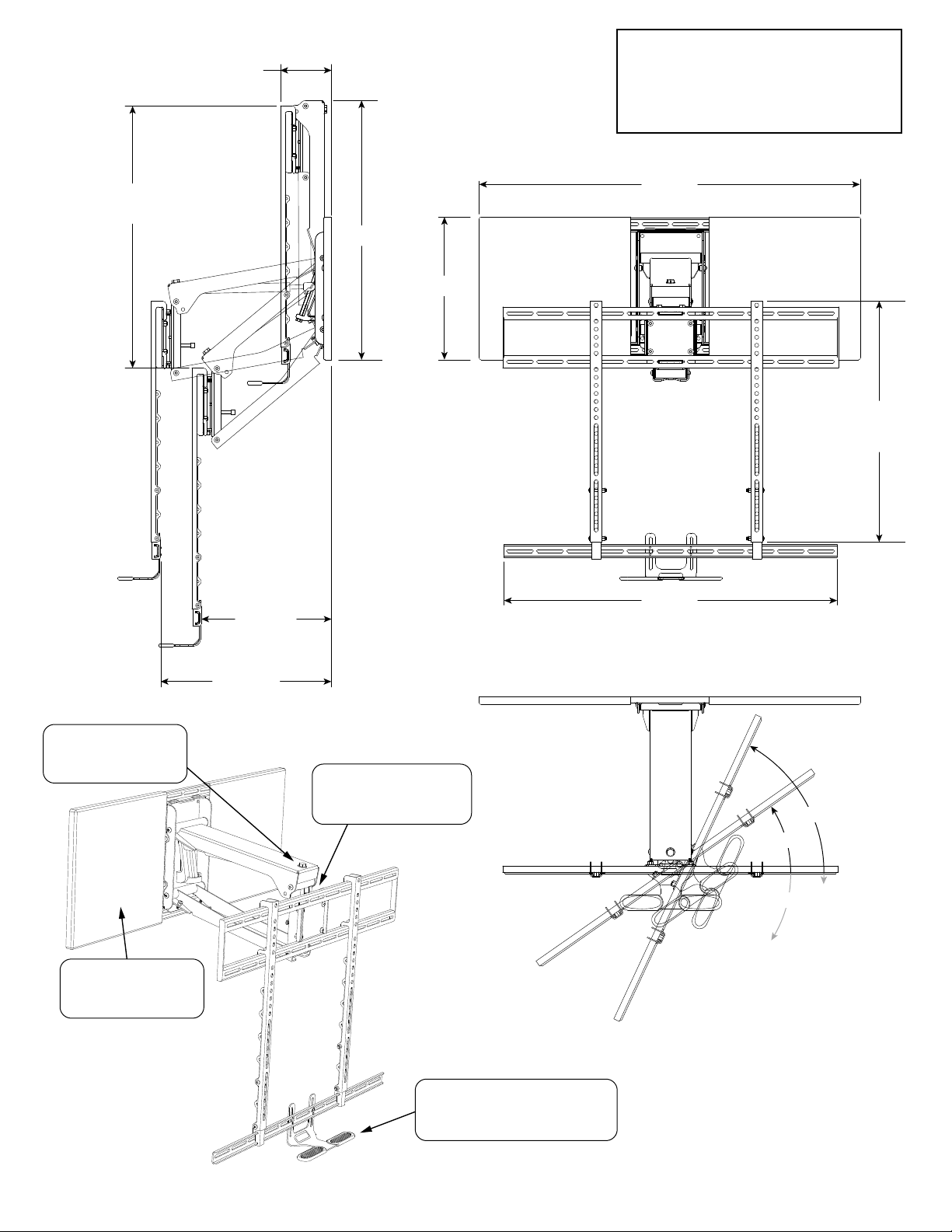
5.00
Thickness
customer service:
(800)-897-9755
www.MantelMount.com
26.0
Maximum Drop
37.5
25.3
14.0
23.6
Min. TV
Height
32.7
12.75
Min. Clearance
Auto-Stabilization:
Pivot automatically balances
the force of the Gas Springs
so the mount stays level
Wall Covers:
Can be painted to match the
wall and conceal the mount
frame
16.75
Max. Clearance
Auto-Straightening:
Flattens the TV as it is raised
to the upper position to prevent
rotation into the wall
Temperature-Sensing Handles: Change
to red color at temperatures above 110ºF
to warn users that the replace is too hot
60°R
35°R
35°L
for TV safety
PAGE 20 MantleMount MM700
 Loading...