

Page 1

MT-3000
Mobile Telecom. Trainer
[MT-3000]
User manual
10th March. 2009
Man & Tel Co., Ltd.
Man & Tel <1/7 > www.manntel.com
Page 2
MT-3000
1. System configuration
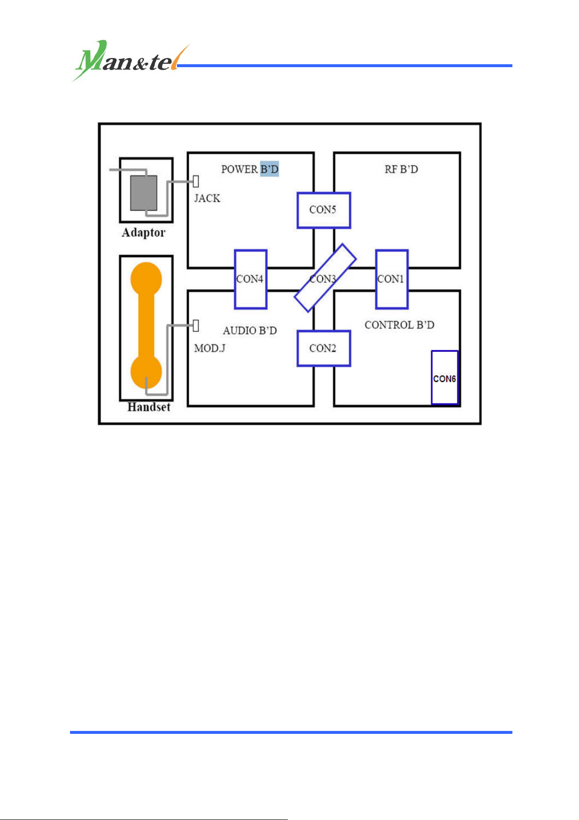
SYSTEM CONNECTION DIAGRAM
2. POWER Supply
1) Connect adaptor output terminal to the jack on the power board.
2) Connect adaptor Input Terminal to the Power board.
Adaptor supply voltage is 110~240V 50~60Hz input, 9V 300mA output
and center positive.
3) Power on sequence is as follows;
Power board > Audio board > RF board > Control board.
3. Handset connection
Connect Handset to the connector of Audio board.
4. AUTO / MANUAL Mode setting
By pressing “MODE” button on Control board, AUTO or MANUAL mode
can be selected and the selected MODE will be displayed on Text LCD.
Man & Tel <2/7 > www.manntel.com
Page 3

MT-3000
5. Basic setting
1) Manual Mode
This mode is used for a detailed board level experiment or for a
manual mode experiment using Key Matrix on Control board – such as
channel selection, voice communication, transmitting power on/off,
audio mute, data transmitting.
Operating sequence is as follows
① Connect adaptor Output terminal to the jack of Power board.
② Power on sequence is as follow;
POWER board ⇒ AUDIO board ⇒ RF board ⇒ CONTROL board
③ Identification code between BS and MS should be same. It can be done
with 4bit dip switch on Control board.
④ By pressing “MODE”button on Control board, user can set up
communication status as “MOD:MANU”and text LCD shows mode
status. User can easily do this mode setting to both of MS and BS
via same methods.
⑤ Channel setting: user can choose the channel by pressing Key matrix
on Control board.
⑥ Channel setting method : for example, if user want to set up channel
no 5, user have to press “CHAN”button →“0”button →
“5”button →“CHAN”button again.
⑦ Here, please take Handset from MS and BS and do a voice
communication each other. Make sure “SIG/MIC” switch on the
Audio board should be set to “MIC”.
⑧ Audio mute : transmitting audio will be mute when user press the
“AUD MUTE”button. Mute LED will be “ON”state. Pressing “AUD
MUTE”button once more will put back to normal status.
⑨ Data communication : Press “TX-DATA”button on the Control board
keypad. Then, data will be transmitted. Press “TX-DATA”button
again to finish data transmission.
⑩ Transmitting power on/off ; Pressing “TX-PWR”button will turn off
transmitting power. Press it again will turn on the power supply.
Man & Tel <3/7 > www.manntel.com
Page 4
MT-3000
2) AUTO 모드
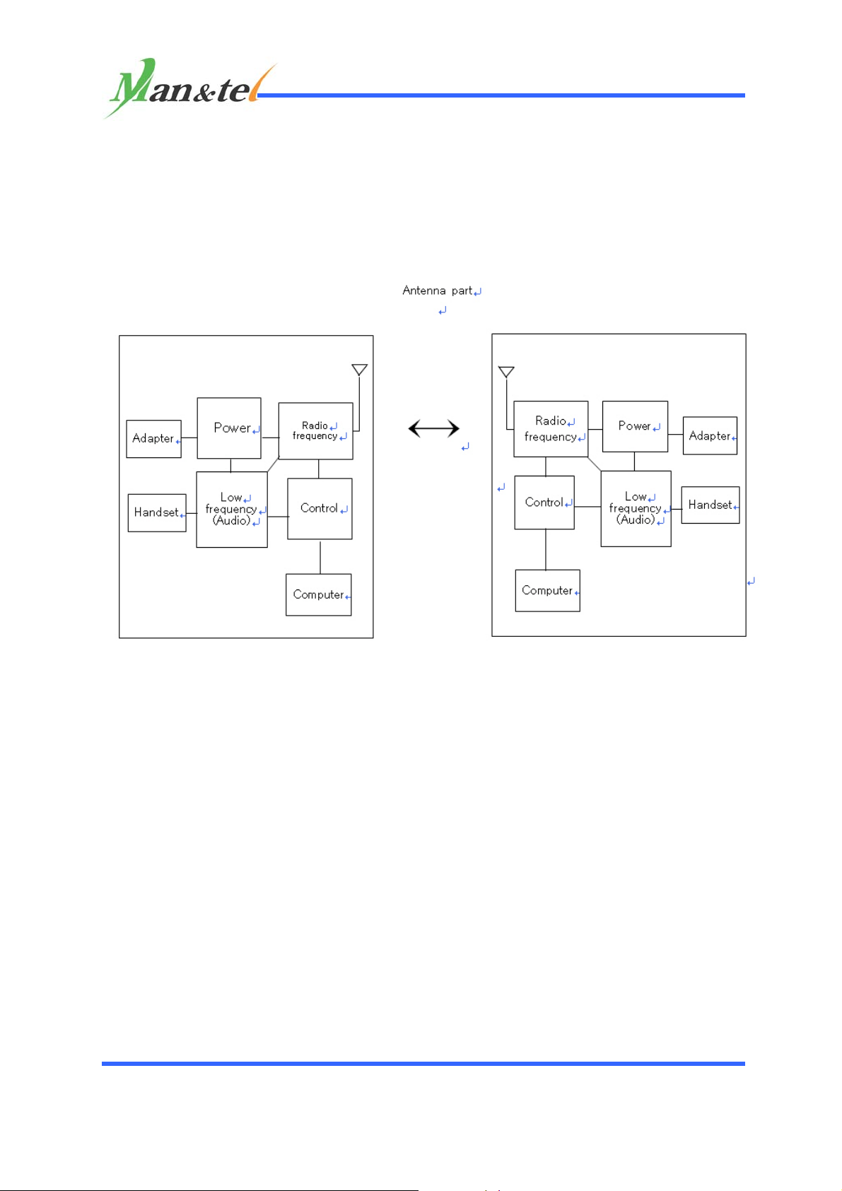
Under this mode, system will operate just like a real commercial
product. Following diagram shows system component for a motion
experiment under auto mode. Operating sequence is as follows;
.
Identification code between BS and MS should be matched. It can be
done with 4 bit dip switch on the Control board.
① By pressing “MODE”button on Control board, user can set up the
communication status as “MOD:AUTO”and this status is displayed
on text LCD. Setting method is same to MS and BS both.
② If the mode is set up to “MOD:AUTO”, then please “CALL”button
from MS(or BS). [here, if user want to cancel the “CALL”status,
please press “CALL”button again.]
③ If user press “CALL”button at BS[MS], then one empty channel will
be chosen. And radio wave will be transmitted from BS[MS] to
MS[BS].
④ Then, MS[BS] come to receive the Radio signal by increasing channel
number and analysis ID code till receive same ID code.
Man & Tel <4/7 > www.manntel.com
Page 5
MT-3000
⑤ If MS[BS] receive same ID code from BS[MS] then MS[BS] became
ringing.
⑥ After ringing, user of MS[BS] press “Talk” button and pick up the
handset and can make voice communication between BS[MS]. At this
stage, the SIG/MIC switch direction should be at“MIC”.
⑦ Communicate with Handsets.
⑧ If user want to stop the voice communication, please press
“TALK”button in BS or MS.
3) Chatting program (working only at “Manual” Mode)
Please press “MODE” button from control B`d and please make
“MOD:MANU”.
① Please connect RS-232 cable between control board and computer.
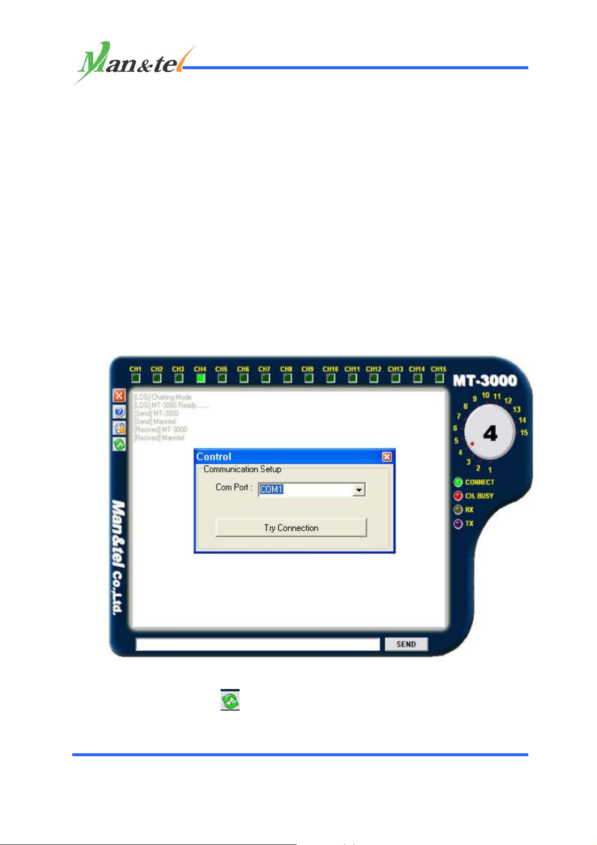
② Please install s/w program to computer. then, below chatting screen
will be appeared.
③ If user press the
④ In this screen, select the “COM port”and press the “OK”button.
⑤ Automatically chatting program and device will be connected, and
button, small window screen will be opened.
Man & Tel <5/7 > www.manntel.com
Page 6

MT-3000
press “Try Connecton” button. Then, the ring like beep sound up.
⑥ Set channel from round circle(named NOVE) which is shaped like the
watch locating at top right corner on window screen.
[ Caution : Don’t set the channel manually using the control
board ]
Please input some data to Input window on computer and press
“SEND” button for transmitting.
◈ Caution in chatting ◈
1. Channel setting should be done by using KNOB on chatting
window screen. By doing so, MT3000 H/W system and Chatting program
can be set up for the communication.
If and although channel setting be manually done from Key matrix
part of Control board, the changed channel will not be shown to
the Chatting program.
That is, although user manually changed the channel from Key
matrix part on Control board the changed channel will not be
transmitted to Chatting program.
2. When try to chat, user have to make a same channel between MS
and BS.
3. Due to low speed, some letters can be omitted while chatting.
In case of English, although 1 letter is omitted user can
recognize the next letter because 1 letter is 1 byte. But is case
of Korean language, if 1 byte is omitted the next letter can be
unrecognizable because Korean’s 1 letter is 2 byte.
1. Signal Input Test (test from “MANU “ Mode)
A. Please set “SIG/MIC”switch direction to “SIG”on Audio
board.
B. Please do a test by connecting “SIG.IN”terminal port and
using Low Frequency Generator.
Man & Tel <6/7 > www.manntel.com
Page 7

MT-3000
===========================================================================
Records of Change
Date Revision Reason for Change
Man & Tel <7/7 > www.manntel.com
 Loading...