

Page 1

OPERATION AND REFERENCE MANUAL
MODULAR TEST SYSTEM
First Edition
March 2001
MTS-3000 SERIES
Tel: +1(905) 828-6 469 Fax: +1(905) 828-6850
e-mail: support@mantatest. com Internet: http://www.mantatest.com
Manta Test Systems Incorporated
4060B Sladeview Crescent, Unit #1
Mississauga, Ontario, L5L 5Y5, Canada
Page 2

MTS-3000 Modular Test System
Operati on and R eference Manual
All rights reserved by Manta Test Systems Incorporated. No part of this publication may be reproduced or
distributed in any form or by any means without the permission of Manta Test Systems Incorporated.
The information and specifications contained within from Manta Test Systems are believed to be accurate
and reliable at the time of printing. However, because of the nature of this product, specifications shown in
this manual are subject to change without notice.
The features and capabil ities described herein reflect those available in the following firmware versions:
• MTS-3000: 2.0
• MTS-3010: 1.1
• MTS-3020: 1.1
• MTS-3030: 2.0
• MTS-3040: 2.0
• MTS-3060: 2.0
March 2001.
Document ID#: CU M004 01A
Powertest™ is a trademark of Manta Test Systems Inc.
Tel: +1(905) 828-6469 Fax: +1(905) 828-6850
e-mail: support@mantatest.com Internet: http://www.mantatest.com
Toll-free technical support (U.S.A & Canada): 1-800-233-8031
Manta Test Sys tems Incorporated
4060B Sladeview Crescent, Unit #1
Mississauga, Ontario, L5L 5Y5, Canada
Page 3

TABLE OF CONTENTS
TABLE OF CONTENTS
Section 1
Introduction
1.1 DISTINCTIVE CHARACTERISTICS .........................................................1-1
1.2 GENERAL DESCRIPTION..........................................................................1-1
1.3 APPLICATIONS...........................................................................................1-2
1.3.1 Standard Applications..............................................................................1-2
1.4 TERMINOLOGY ...... ...... .... ...... .... ...... .... ........... .... ...... .... ...... .... ...... .... ...... ..1-2
1.4.1 AC Current Module (ACI)........................................................... .......... ..1-2
1.4.2 AC Voltage Module (ACV).....................................................................1-2
1.4.3 Control Module (CM).............................................................................. 1-2
1.4.4 Device Under Test (DUT) .......................................................................1-2
1.4.5 Dynamic Fault Mode ...............................................................................1-2
1.4.6 Dynamic Relay Testing ...........................................................................1-3
1.4.7 MTS.........................................................................................................1-3
1.4.8 On Panel Testing......................................................................................1-3
1.4.9 Programming Mode.................................................................................1-3
1.4.10 Static Relay Testing.................................................................................1-3
1.4.11 Test Mode ................................................................................................1-3
1.4.12 V/I Module (VI).......................................................................................1-3
1.4.13 WFG Module...........................................................................................1-3
1.5 SAFETY CONSIDERATIONS.....................................................................1-3
1.6 TECHNICAL CONSIDERATIONS.............................................................1-4
1.7 TECHNICAL SUPPORT ..............................................................................1-4
Section 2
Specifications
2.1 INPUTS .........................................................................................................2-1
2.2 OUTPUTS .....................................................................................................2-1
2.2.1 MTS-3010 Digital I/O Module (Optional)..............................................2-1
2.2.2 AC Currents: MTS-3060 AC Current Module........................................2-1
2.2.3 AC Voltage and Current: MTS-3030 AC Voltage/Current Module........2-2
2.2.4 Output frequency .....................................................................................2-2
2.2.5 Harmonics................................................................................................2-1
2.2.6 Phase control............................................................................................2-2
2.2.7 DC Voltage: MTS-3020 DC Voltage Module.........................................2-2
2.2.8 DC Current: Current Source option.........................................................2-2
2.2.9 MTS-3010 Digital I/O Module (Optional)..............................................2-2
2.3 METERING...................................................................................................2-3
2.3.1 Time measurement...................................................................................2-3
2.3.2 Frequency measurement ..........................................................................2-3
2.4 STATIC/DYNAMIC TESTING CAPABILITIES........................ .... ...... .... ..2-3
2.5 OPTIONS.......................................................................................................2-3
2.5.1 System Options ........................................................................................2-3
2.5.2 AC Voltage Module Options ...................................................................2-3
CU M004 01A
MTS-3000 SERIES OPERATION AND REFERENCE MANUAL iii
0$17$#7(67#6<67(06
Page 4

TABLE OF CONTENTS
2.5.3 AC Current Module Options....................................................................2-4
2.5.4 AC Voltage/Current Module Options......................................................2-4
2.6 PHYSICAL CHARACTERISTICS ..............................................................2-4
2.6.1 Minimum Configuration..........................................................................2-4
2.6.2 Control Module........................................................................................2-4
2.6.3 AC Voltage Module.................................................................................2-4
2.6.4 AC Current Module .................................................................................2-4
2.6.5 AC Voltage/Current Module ...................................................................2-4
2.6.6 Three Phase System: Control Module, AC Voltage and AC Current
Modules ...................................................................................................2-4
Section 3
Operation Summary
3.1 FRONT PANEL LAYOUT...........................................................................3-1
3.1.1 MTS-3000 Control Module, CM.............................................................3-1
3.1.2 MTS-3010 Digital I/O Module................................................................3-4
3.1.3 MTS-3010 DC Voltage Source................................................................3-5
3.1.4 MTS-3040 AC Voltage Module ..............................................................3-5
3.2 REAR PANEL LAYOUT .. ...... .... ...... .... ........... .... ...... .... ...... .... ...... .... ...... ....3-7
3.2.1 MTS-3000 Control Module Rear Panel...................................................3-7
3.3 BASIC APPLICATIONS ..............................................................................3-9
3.3.1 Getting Started.........................................................................................3-9
3.3.2 Basic AC Voltage, Current and Phase Angle Output ..............................3-12
3.3.3 Frequency Output ....................................................................................3-14
3.3.3.1 BASIC FREQUENCY OUTPUT. ...................................................3-14
3.3.3.2 ADVANCED FREQUENCY OUTPUT. ....................... ...... .... ...... ..3-15
3.3.4 DC Voltage ..............................................................................................3-15
3.3.4.1 BASIC DC VOLTAGE OUTPUT. .................................................3-15
3.3.4.2 ADVANCED DC VOLTAGE OUTPUT. . .... .... ...... .... ...... .... ...... .... 3-16
3.3.5 DC Current Output...................................................................................3-16
3.3.6 High AC Voltage Output.........................................................................3-17
3.3.7 High AC Current Output..........................................................................3-18
3.3.8 Overcurrent Relay Test............................................................................3-18
3.3.8.1 SETUP. ............................................................................................3-19
3.3.8.2 MINIMUM PICKUP TEST. ............................................................3-19
3.3.8.3 INVERSE-TIME CHARACTERISTIC TEST. ...............................3-19
3.3.8.4 INSTANTANEOUS ELEMENT TEST. .........................................3-20
3.3.8.5 TARG ET/SEAL-I N TEST. .. ........ ......... ................ ........ ................ ..3-21
3.3.9 Differential Relay - Three Terminal Type ..............................................3-22
3.3.9.1 PICKUP TEST. ................................................................................3-22
3.3.9.2 OPERATE TIME TEST. .................................................................3-23
3.3.9.3 HARMONIC RESTRAINT TEST. ................................................3-23
3.3.9.4 INSTANTANEOUS TEST. ............................................................3-24
3.3.9.5 TARGET TEST. .............................................................................3-24
3.3.10 Differential Relay - Independent Coil Type ............................................3-25
3.3.10.1 SLOPE TEST. ..................................................................................3-25
iv MTS-3000 SERIES OPERATION AND REFERENCE MANUAL
0$17$#7(6 7#6<67(06
CU M004 01A
Page 5

TABLE OF CONTENTS
3.3.10.2 OPERATE TIME TEST. .................................................................3-26
3.3.10.3 HARMONIC RESTRAINT TEST. .................................................3-27
3.3.10.4 INSTANTANEOUS TEST. .............................................................3-27
3.3.10.5 TARGET TEST. ..............................................................................3-28
3.3.11 Voltage Relay Test...................................................................................3-28
3.3.11.1 SETUP. ...........................................................................................3-28
3.3.11.2 MINIMUM PICKUP TEST. ...........................................................3-29
3.3.11.3 TIMING TEST. ..............................................................................3-29
3.3.11.4 TARGET/SEAL-IN TEST. .............................................................3-30
3.3.12 Frequency Relay Test ..............................................................................3-30
3.3.12.1 SETUP. ............................................................................................3-30
3.3.12.2 PICKUP TEST. ................................................................................3-30
3.3.12.3 TIMING TEST. ...............................................................................3-31
3.3.12.4 TARGET/SEAL-IN TEST. .............................................................3-31
3.3.12.5 UNDERVOLTAGE INHIBIT TEST. .............................................3-32
3.3.13 Synchronizing/Reclosing or Synchrocheck Relay...................................3-33
3.3.13.1 PHASE ANGLE LIMIT TEST. ....................................................... 3-33
3.3.13.2 VOLTAGE LIMIT TEST. ...............................................................3-33
3.3.13.3 SLIP FREQUENCY LIMIT TEST. .................................................3-34
3.3.14 Single Phase Impedance Relay or Directional Overcurrent Relay Test..3-35
3.3.14.1 SETUP. ............................................................................................3-35
3.3.14.2 REACH/MINIMUM PICKUP TEST. ..............................................3-35
3.3.14.3 MTA TEST. .....................................................................................3-36
3.3.14.4 OPERATE TIME TEST. .................................................................3-36
3.3.15 Three Phase Impedance Relay Test .........................................................3-37
3.3.15.1 PREPARATION. ............................................................................3-38
3.3.15.2 REACH TEST. ...............................................................................3-39
3.3.15.3 MTA TEST. .....................................................................................3-40
3.3.15.4 OPERATE TIME TEST. .................................................................3-40
3.3.16 Ground Fault Overvoltage Relay.............................................................3-41
3.3.16.1 SETUP. ...........................................................................................3-41
3.3.16.2 OVERVOLTAGE PICKUP TEST. ................................................3-42
3.3.16.3 OVERVOLTAGE TIMING TEST. ................................................3-42
3.3.16.4 UNDERVOLTAGE INHIBIT TEST. ............................................3-42
3.3.17 DC Auxilliary/Time-Delay Relay Test....................................................3-42
3.3.17.1 PICKUP TEST. ...............................................................................3-42
3.3.17.2 TIMING TEST. ..............................................................................3-43
4.1 FAULT STATES...........................................................................................4-1
4.1.1 Prefault State............................................................................................4-1
4.1.2 Fault State ................................................................................................4-1
4.1.3 Postfa u l t S t a t e ... ........ ........ ........ ................. ........ ................ ........ .............. 4 -1
4.2 CHARACTERISTICS OF FAULT STATES ...............................................4-1
4.3 OPERATION MODE - STATIC VS. DYNAMIC .......................................4-2
CU M004 01A
MTS-3000 SERIES OPERATION AND REFERENCE MANUAL v
Section 4
Detailed Operation
0$17$#7(67#6<67(06
Page 6

TABLE OF CONTENTS
4.3.1 Static Fault Mode.....................................................................................4-2
4.3.2 Dynamic Fault Mode ...............................................................................4-3
4.4 TRIGGER/TIMER OPERATION.................................................................4-4
4.4.1 External Trigger Inputs............................................................................4-4
4.4.2 Trigger Threshold Levels.........................................................................4-4
4.4.3 Start Trigger (FLT) ..................................................................................4-4
4.4.4 Stop Trigger (TRIP).................................................................................4-5
4.4.5 Reset.........................................................................................................4-5
4.4.6 Timer Start ...............................................................................................4-5
4.4.7 Two-Wire Pulse Timing ..........................................................................4-5
4.4.8 Timing in Cycles......................................................................................4-5
4.4.9 Testing SCR Output Type Relays............................................................4-5
4.5 CURRENT MODES......................................................................................4-6
4.5.1 Curre n t Rang e ............. ................ ........ ......... ................ ........ ................ ....4-6
4.5.2 HARMONIC Current Mode ....................................................................4-7
4.5.2.1 DEFINITION OF PERCENTAGE HARMONIC. ..........................4-8
4.5.2.2 SPECIAL N O TES. ..... ................ ......... ........ ................ ........ ............4-8
Section 5
Advanced Operation
5.1 MENU OPERATION ....................................................................................5-1
5.1.1 Basic Usage..............................................................................................5-1
5.1.1.1 ACTIVATING THE MAIN MENU. ..............................................5-1
5.1.1.2 SELECTING MENU ITEMS. ........................................................5-1
5.1.1.3 MENU NAVIGATION. .................................................................5-1
5.2 SETTINGS.....................................................................................................5-5
5.2.1 Reset to Defaults......................................................................................5-5
5.2.2 Fault Type................................................................................................5-5
5.2.2.1 VECTOR MODE. ...........................................................................5-5
5.2.2.2
Φ−N,Φ−Φ, 3Φ
MODE. ............................................................................5-5
5.2.3 Harmonics................................................................................................5-6
5.2.3.1 HARMONICS OPTIONS. ..............................................................5-6
5.2.4 Parallel Current........................................................................................5-6
5.2.5 Ramps ......................................................................................................5-7
5.2.5.1 FREQUENCY RAMPING. ............................................................5-8
5.2.5.2 PHASE RAMPING. .......................................................................5-8
5.2.5.3 VOLTAGE RAMPING. .................................................................5-8
5.2.5.4 CURRENT RAMPING. .................................................................5-8
5.2.6 Frequency 2..............................................................................................5-8
5.2.7 Breaker Times (
5.2.8 AC Current Range
Bkr Times
(ACI Range)
)......................................................................5-9
..............................................................5-9
5.2.9 Reclose.....................................................................................................5-9
5.2.10 Fault Incidence Angle
5.2.11 Maximum Fault Duration
(FIA)
....................................................................5-10
(Max Flt Dur)
................................................5-10
5.2.12 Display Options .......................................................................................5-10
5.2.12.1 DEFAULT DISPLAY
(Hz &
Φ)
. ..................................................5-10
vi MTS-3000 SERIES OPERATION AND REFERENCE MANUAL
0$17$#7(6 7#6<67(06
CU M004 01A
Page 7

TABLE OF CONTENTS
5.2.12.2 SLOPE. ...........................................................................................5-11
5.2.12.3 IMPEDANCE. ................................................................................5-11
5.2.12.4 FREQUENCY & V/Hz. ..................................................................5-13
5.2.12.5 FREQUENCY & SLIP. ..................................................................5-13
5.3 QUICK TEST ................................................................................................5-13
5.4 PREFERENCES............................................................................................5-15
5.4.1 Button Tone .............................................................................................5-15
5.4.2 VI Module #1...........................................................................................5-15
5.4.3 VI Module #2...........................................................................................5-15
5.4.4 COM 1 RS-232 ........................................................................................5-15
5.4.5 COM 2 RS-232 ........................................................................................5-15
5.4.6 Assign Ports .............................................................................................5-15
5.4.7 LCD Contrast...........................................................................................5-16
5.5 INDEX...........................................................................................................5-18
5.6 OTHER ..........................................................................................................5-18
5.6.1 Version.....................................................................................................5-18
5.6.2 Calibration ...............................................................................................5-18
5.6.3 Printer Test...............................................................................................5-18
5.6.4 Diagnostics...............................................................................................5-18
5.7 DIGITAL I/O.................................................................................................5-20
5.7.1 Input Channel 1 (
5.7.1.1
TRIP (ie STOP)
5.7.1.2 EXTERNAL START
5.7.1.3
5.7.1.4
5.7.1.5
5.7.1.6
5.7.1.7
Pulse Timing.
Reset.
...............................................................................................5-20
Reclose.
Foot Switch.
Off.
..................................................................................................5-21
5.7.2 Input Channel 2 (
5.7.3 Input Debounce (
5.7.4 DC Current (
5.7.5 Output Channel 1 (
5.7.5.1
5.7.5.2 /
FAULT (NO)
FAULT (NC)
5.7.5.3 Breaker Open
5.7.5.4
5.7.5.5
5.7.5.6
PERMISSIVE
UNBLOCK
Off.
..................................................................................................5-22
5.7.6 Output Delay (
5.7.7
Version
.....................................................................................................5-22
I/P Chan 1
) ..................................................................5-20
. ..............................................................................5-20
(FLT (i e ST O P))
. .........................................5-20
..................................................................................5-20
...........................................................................................5-20
....................................................................................5-20
I/P Chan 2
I/P Debounce
IDC
) ...................................................................................5-21
O/P Chan 1
) ................................................................5-21
) .............................................................5-21
) .............................................................5-21
. ..................................................................................5-21
. .................................................................................5-21
(BKR OPEN : 52 B)
. ..................................................5-21
. .................................................................................5-22
. .....................................................................................5-22
O/P Delay
) ......................................................................5-22
6.1 ADVANTAGES OF QUICKTEST................... ...... .... ...... .... ...... .... ...... .... ....6-1
6.2 QUICKTEST ALGORITHMS......................................................................6-1
CU M004 01A
MTS-3000 SERIES OPERATION AND REFERENCE MANUAL vii
Section 6
QuickTest
0$17$#7(67#6<67(06
Page 8

TABLE OF CONTENTS
6.3 QUICKTEST TERMINOLOGY AND ABBREVIA TIONS ........................6-2
6.4 SUMMARY OF OPERATION.....................................................................6-2
OVERCURRENT TEST
6.5 TIMED 1
Φ
..............................................................6-4
6.5.1 Test Description.......................................................................................6-4
6.5.2 Example 1Φ Test Descriptions ................................................................6-4
6.6 INSTANTANEOUS 1Φ OVERCURRENT TEST ......................................6-6
6.6.1 Test Description.......................................................................................6-6
6.6.2 Example 1Φ Instantaneous Over Current (50).........................................6-6
6.7 TIMED 1Φ UNDER VOLTAGE TEST . .. ......... ...... .... ...... .... ...... .... ...... .... ....6-8
6.7.1 Test Description.......................................................................................6-8
6.7.2 Example 1Φ Timed Under Voltage (27)..................................................6-8
6.8 INSTANTANEOUS 1Φ UNDER VOLTAGE .............................................6-10
6.8.1 Test Description.......................................................................................6-10
6.8.2 Example 1Φ Instantaneous Under Voltage (27) ......................................6-10
6.9 TIMED 1Φ OVER VOLTAGE TEST ..........................................................6-12
6.9.1 Test Description.......................................................................................6-12
6.9.2 Example 1Φ Timed Over Voltage (59)....................................................6-12
6.10 INSTANTANEOUS 1Φ OVER VOLTAGE TEST .....................................6-14
6.10.1 Test Description.......................................................................................6-14
6.10.2 Example 1Φ Instantaneous Over Voltage (59)........................................6-14
6.11 TR A N S FORMER DIFF ERENTIAL TEST. .. ................ ........ ........ .............. 6 -1 6
6.11.1 Test Description.......................................................................................6-16
6.11.2 Example Transformer Differential...........................................................6-17
Section 7
RS-232C Interface
7.1 RS-232C CONNECTION..............................................................................7-1
7.1.1 Interface Specifications............................................................................7-1
7.1.2 COM 1 RS232C Port...............................................................................7-1
7.1.2.1 COM 1 RS-232C CONNECTOR PIN ASSIGNMENTS. ..............7-1
7.1.3 COM 2 RS232C Port...............................................................................7-2
7.1.3.1 COM 1 RS-232C CONNECTOR PIN ASSIGNMENTS. ..............7-2
7.1.4 Baud Rate Selection.................................................................................7-2
7.1.4.1 COM 1 BAUD RATE. .................................... .... ...... .... ...... .... ...... ..7-2
7.1.4.2 COM 2 BAUD RATE. .................................... .... ...... .... ...... .... ...... ..7-2
7.1.5 XON/XOFF Handshaking .......................................................................7-3
7.2 COMMAND DESCRIPTIONS............................. ...... .... ...... .... ...... .... ...... ....7-3
7.2.1 Control Mode Programming......................................... .... ...... .... ...... .... ...7-3
7.2.2 Fault State Control...................................................................................7-3
7.2.3 External Data Mode.................................................................................7-5
7.2.4 Voltage Programming..............................................................................7-5
7.2.4.1 COMMANDS. ................................................................................7-5
7.2.4.2 EXAMPLES. ..................................................................................7-6
7.2.5 Current Control........................................................................................7-6
7.2.6 Phase Control...........................................................................................7-7
7.2.6.1 COMMANDS. ................................................................................7-7
viii MTS-3000 SERIES OPERATION AND REFERENCE MANUAL
0$17$#7(6 7#6<67(06
CU M004 01A
Page 9

TABLE OF CONTENTS
7.2.6.2 EXAMPLES. ..................................................................................7-8
7.2.7 Frequency Control/Programming............................................................7-8
7.2.7.1 COMMANDS. ................................................................................7-8
7.2.7.2 EXAMPLES. ..................................................................................7-9
7.2.8 RS-232 Control........................................................................................7-10
7.2.9 Print Commands ......................................................................................7-12
7.2.10 Other Commands .....................................................................................7-14
7.2.11 DC Voltage Control .................................................................................7-15
7.2.12 Digital Input/Output and DC Current Control.........................................7-16
7.3 PROGRAMMING HINTS ............................................................................7-17
ALPHABETICAL RS-232 COMMAND SET
APPENDIX A
....................................................................................... ...................... ..........A-1
APPENDIX B
POWERSCOPE PROGRAM
B.1 INTRODUCTION .........................................................................................B-1
B.1.1 Features....................................................................................................B-1
B.1.2 Operation Instructions..............................................................................B-2
B.1.3 Button Bar ...............................................................................................B-2
B.1.4 Configuring the Comm Port ....................................................................B-2
B.1.5 System Configuration ..............................................................................B-3
B.1.6 Operating Modes......................................................................................B-3
B.1.6.1 REAL TIME MODE. .....................................................................B-3
D.1.6.2 DEMO MODE. ...............................................................................B-3
B.1.7 Displaying Phasor & Impedance Diagrams.............................................B-4
B.2 PHASORS WINDOW...................................................................................B-5
B.3 SYMMETRICAL COMPONENTS ..............................................................B-5
B.3.1 Current Components Window.................................................................B-5
B.3.2 Voltage Components Window.................................................................B-6
B.3.3 Interpretation of Symmetrical Components Displays..............................B-7
B.4 IMPEDANCE WINDOW... .... .. .... .... .. .... .... ..... .... .... .. .... .... .. .... .... .. .... .... .. .... ..B-8
B.4.1 Using the Impedance Window................................................. .......... ......B-8
B.4.2 Defining & Displaying Theoretical Relay Characteristics ......................B-9
B.5 POWER WINDOW.......................................................................................B-10
B.6 SPECIAL NOTES .........................................................................................B-10
ALPHABETICAL RS-232 COMMAND SUMMARY
C.1 USER ERRORS - INAPPROPRIATE BUTTON PRESSING.....................C-1
C.2 HARDWARE ALARMS...............................................................................C-2
C.3 SOFTWARE ALARMS................................................................................C-4
CU M004 01A
MTS-3000 SERIES OPERATION AND REFERENCE MANUAL ix
APPENDIX C
0$17$#7(67#6<67(06
Page 10

TABLE OF CONTENTS
............................................................................................................... D-1
.................................................................................................................E-1
GLOSSARY
INDEX
x MTS-3000 SERIES OPERATION AND REFERENCE MANUAL
0$17$#7(6 7#6<67(06
CU M004 01A
Page 11

TABLE OF CONTENTS
LIST OF ILLUSTRATIO NS
Figure Title Page
Number Number
3.1 CONTROL MODULE PANEL.....................................................................3-1
3.2 D IGITAL I/O PA N EL ...... ........ ................ ......... ................ ........ ................ ....3-4
3.3 DC VOLTAGE PANEL................................................................................3-5
3.4 AC VOLTAGE PANEL................................................................................3-6
3.5 CONTROL MODULE REAR PANEL.........................................................3-7
3.6 TYPICAL THREE PHASE SYSTEM ..........................................................3-9
3.7 DISPLAY MESSAGES.................................................................................3-10
3.8 TEST CONNECTIONS.................................................................................3-10
3.9 BASIC AC ADJUSTMENTS........................................................................3-12
3.10 FREQUENCY ADJUST................................................................................3-14
3.11 DC VOLTAGE ADJUST..............................................................................3-15
3.12 DC CURRENT ADJUST ..............................................................................3-16
3.13 AC VOLTAGE VECTOR.............................................................................3-17
3.14 AC CURRENT VECTORS...........................................................................3-18
3.15 OVERCURRENT RELAY TEST .................................................................3-18
3.16 THREE TERMINAL DIFFERENTIAL RELAY TEST...............................3-22
3.17 INDEPENDENT COIL DIFFERENTIAL RELAY TEST ...........................3-25
3.18 VOLTAGE RELAY TEST............................................................................3-28
3.19 SYNCHRONIZING RELAY TEST..............................................................3-33
3.20 IMPEDANC E RELAY TEST .............. ...... ......... ...... .... ...... .... ...... .... ...... .... ..3-35
3.21 THREE PHASE IMPEDANCE RELAY TEST............................................3-37
3.22 IMPEDANC E RELAY TEST DISPLAY ................................................... ..3-38
3.23 GROUND OVERVOLTAGE RELAY TEST...............................................3-41
3.24 DC RELAY PICKUP TEST..........................................................................3-42
3.25 DC RELAY TIMING TEST..........................................................................3-43
4.1 EXAMPLE OUTPUT SEQUENCE (PREFAULT OFF)..............................4-2
4.2 EXAMPLE OUTPUT SEQUENCE (PREFAULT ON) ...............................4-2
4.3 FAULT STATE DIAGRAM FOR STATIC MODE ....................................4-3
4.4 FAULT STATE DIAGRAM FOR DYNAMIC MODE ...............................4-3
4.5 TEST CONNECTIONS FOR SC R OUTPUT TYPE RELAY . .... .... .... .... .... 4-6
4.6 DIFFERENTIAL RELAY HARMONIC RESTRAINT TESTING .............4-7
5.1 ROOT MENU................................................................................................5-1
5.2 MENU TREE SETTINGS.............................................................................5-4
5.3 PARALLEL MENU ......................................................................................5-7
5.4 PARALLEL CONNECTION........................................................................5-7
5.5 MENU TREE: PREFERENCES...................................................................5-14
5.6 MENU TREE: INDEX/OTHER....................................................................5-17
5.7 MENU TREE: DIGITAL I/O ........................................................................5-19
CU M004 01A
MTS-3000 SERIES OPERATION AND REFERENCE MANUAL xi
0$17$#7(67#6<67(06
Page 12

TABLE OF CONTENTS
xii MTS-3000 SERIES OPERATION AND REFERENCE MANUAL
0$17$#7(6 7#6<67(06
CU M004 01A
Page 13

INTRODUCTION - Section 1
INTRODUCTION
1.1 DISTINCTIVE CHARACTERISTICS
• Unique expandable modular design.
• Economical.
• Individual display and control of all voltages,
currents and phase angles.
• Built in “Quick-Test” functions for most
common relay elements.
• Output test reports directly to a printer.
• On- or Off-line programming via keypad and/or
rotary knob.
• Many productivity enhancing features.
• Static and dynamic testing.
• Compact and rugged.
1.2 GENERAL DESCRIPTION
The Manta MTS-3000 is a flexible modular test system, geared particularly towards protective relay
testing, but configurable for numerous other applications requiring AC and/or DC voltage and/or current
sources.
Systems can be as simple as a single phase AC current source, or as complex as a full three phase AC
voltage and current source with DC voltage and current, multi-channel digital input operation sensing and
digital output control, and accurate timing measurement capability. Multi-system control, with one system
functioning as the master to one or more slave units, is also possible. An economically priced system may
be configured with only the minimum number of features required for today’s applications, with the
flexibility to expand as tomorrow’s requirements and budgets dictate.
The MTS-3000 is specifically engineered for a short learning curve. A ‘Vector Control’ mode provides
for individual amplitude and phase adjustment of all AC voltage and current outputs, with the added
convenience of numeric keypad input for quick absolute control settings, or rotary knob control of
incremental changes to settings. Additional ‘intelligent control’ modes automate much of the setup
required for three phase test applications, and provide single-input control of multiple parameters as
found, for example, during phase-to-phase or three phase fault simulations.
A unique feature of the equipment is its ability to automatically test many protective relays using built-in
automated test routines. This permits fast, consistent testing for routine work that may not justify the
expense and learning curve necessary for full computer based testing. Field reports can be generated on
the spot using a portable printer.
CU M004 01A
0$17$#7(67#6<67(06
MTS-3000 OPERATION AND REFERENCE MANUAL 1-1
Page 14

INTRODUCTION - Section 1
An MTS-3000 System consists of a Control Module (CM), and one or more AC output modules. These
modules connect together to form a stack, with the control module at the top.
An AC Current Module (ACI), an AC Voltage Module (ACV), or an AC Voltage/Current Module (ACV/
I) may be easily added or removed from a stack to configure the system to your needs. All the required
electrical connections are made when a module is added to the stack. The CM recognizes and configures
the system for all the modules in a stack on power up. This "plug and play" capability allows modules to
be added or removed at any time.
1.3 APPLICATIONS
1.3.1 Standard Applications
•
Static and dynamic testing of virtually all protective relays.
•
Calibration and verification of V, I, W, Z, and Frequency transducers.
•
T esting of fault recorders, fault locators, and automatic voltage regulators.
•
Testing and calibration of metering systems.
1.4 TERMINOLOGY
The following terminology is use d throughout this user’s guide:
1.4.1 AC Current Module (ACI)
The AC current module or ACI refers to the MTS-3060 module. This module can have from one to three
AC current chan nels.
1.4.2 AC Volt age Module (ACV)
The AC voltage module or ACV refers to the MT S- 3040 module. This module can have from one to three
AC voltage channels.
1.4.3 Control Mo du l e (CM )
Control module or CM refers to the upper most module that makes up the MTS stack.
1.4.4 Device Under Test (DUT)
DUT refers to the protective relay or similar device being tested.
1.4.5 Dynamic Fault Mode
This mod e re fers to t he fault mode that’s used w he n p erforming operate time t est s. See Section 4. 3 .2 fo r a
detailed explanat ion.
1-2 MT S-3000 OP ERA TIO N AND REFERE NCE MANUAL
0$17$#7(67#6<67(06
CU M004 01A
Page 15

INTRODUCTION - Section 1
1.4.6
Dynamic Relay Testing
Dynamic relay testing refers to testing of relays using instantaneous steps and/or ramping of voltage and
current inputs. To closely simulate the conditions the device sees in service, the voltages and currents are
typically stepped from a nominal, prefault level, to a predetermined fault level.
1.4.7 MTS
The "modular test system" MTS-3000 and its various optional modules.
1.4.8
On Panel Testing
This refers to testing of relays and relay systems while they’re installed on panels or equipment racks.
This involves injecting voltages or currents directly into the panel to test the complete system response,
and to verify the correct input/output wiring and phasing of the panel.
1.4.9 Programming Mode
Programming mode is used to preset AC output parameters for either prefault or fault state. The AC
outputs are disabled while the system is in programming mode.
1.4.10 Static Relay Testing
This refers to relay testing by slowly varying inputs to accurately locate pickup points and to perform
repeatable measurements.
1.4.11 Test Mode
The AC outputs are enabled while in test mode.
1.4.12 V/I Module (VI)
The V/I module or VI refers to the MTS-3030 module. This module can be ordered with either one or two
convertable AC output channels. Each channel can operate in either voltage mode (0-150 V), or current
mode (0-25 A).
1.4.13 WFG Module
WFG refers to waveform generation modules such as the MTS-3030, MTS-3040, and MTS-3060.
1.5 SAFETY CONSIDERATIONS
The MTS-3000 can generate high levels of current and voltage. Incorrect usage may cause personal injury
and/or damage to the instrument. The user must be qualified to work safely in the intended application
environment of this instrument. Non-adherence to the following minimum requirements constitutes
misuse of the Modular Test System, MTS, and the manufacturer accepts no liability for damages arising
from such misuse.
CU M004 01A
0$17$#7(67#6<67(06
MTS-3000 OPERATION AND REFERENCE MANUAL 1-3
Page 16

INTRODUCTION - Section 1
The instrument case must always be effectively grounded. The rear panel grounding stud of the Control
Module, CM, must be connected by a minimum 12-gauge wire to a known secure ground. This ground is
in addition to the power cord ground.
All leads and connectors must be in good condition and rated for the voltage and current carrying
requirements. Current outputs must be securely connected with a minimum 12 gauge leads with C-hook
term ina ls.
MTS outputs must not be connected to live outputs or to live equipment. All outputs must be turned off
before making any changes to the connec tions. Never exceed the following maximum ratings:
(a) 300V rms to ground on any input, power or control.
(b) 300VDC differential to the contact (external trigger) inputs.
(c) 5Arms or 5A DC through any contact output.
All rear panel fuses must contain properly rated fuses.
1.6 TECHNICAL CONSIDERATIONS
The optional DC current source, when enabled, will source up to 2.5A of DC current out of the two left
terminals of Input 1 of the DIGITAL I/O module. The low impedance nature of this source could provide
the necessary trip path to inadvertently trip an auxillary relay or circuit breaker. The DC current output
only should be used when the protective relays trip output circuit is properly isola te d.
1.7 TECHNICAL SUPPORT
The design of the MTS reflects decades of experience in the electric power industry. However, we
recognize that situations may be encountered that were not considered during its design. We encourage
you to forward any questions, problems or suggestions to us either through the representative from whom
you purchased your system, or directly to us via the phone, fax or e-mail numbers found on the front
cover.
1-4 MT S-3000 OP ERA TIO N AND REFERE NCE MANUAL
0$17$#7(67#6<67(06
CU M004 01A
Page 17

SPECIFICATIONS
NOTE: All specifications are subject to change. All AC quantities are RMS values, except as
otherwise noted.
Power outputs are specified for nominal 120VAC/60Hz or 240VAC/50Hz power input,
and 25°C ambient operating temperature.
For some configurations, the 15A / 7.5A rating may be exceeded if all outputs are at
full power. Derating applies for lower input power voltages and higher ambient
temperatures. For all current outputs, maximum obtainable current will vary inversely
with load impedance. For extended operation at high power output levels, ensure
adequate cooling (i.e. don’t obstruct cooling intakes or exhaust outlets).
2.1 INPUTS
110-130 VAC @ 15A, Single phase, 47-63 Hz, or
210-250 VAC @ 7.5A, Single phase, 47-63 Hz (Future)
SPECIFICATIONS - Section 2
2.1.1 MTS-3010 Digital I/O Module (Optional)
NC or NO wet/dry contact inputs, Start/Stop trigger inputs for fault initiation/termination
Programmable contact de-bounce delay, 0.1 - 999.9 msec, 0.1 msec resolution
300VDC/AC maximum, fully isolated (12V threshold level, 52K ohms impedance minimum)
2.2 OUTPUTS
2.2.1 AC Voltages: MTS-3040 AC Voltage Module
One to three direct coupled outputs depending on configuration, connected wye (common neutral)
0-150V rms phase to neutral, direct coupled
100 VA per phase maximum @ 70V Φ-N output, P.F.=1.0
125 VA per phase maximum @ 150V Φ-N output, P.F.=1.0
Setting resolution 0.01V:Accuracy greater of 0.25% of setting or 0.1% of full scale
Fully short circuit proof and thermal overload protected
2.2.2 AC Currents: MTS-3060 AC Current Module
0-25A rms, 250 VA maximum per channel, direct coupled
12A rms continuous
Three-phase wye current: 12A rms continuous per channel
25A rms per channel into 0.25 ohm load
Single phase current, three channels in parallel, high current range: 0-75A rms, 300 VA, 30% duty cycle
Single phase current, three channels in parallel, high voltage range: 0-35A rms, 600 VA, 30% duty cycle
Fully open and short circuit proof and thermal overload-protected
Setting resolution 0.001 Amps: Accuracy greater of 0.25% of setting, or 0.1% of full scale
CU M004 01A
MTS-3000 OPERATION AND REFERENCE MANUAL 2-1
0$17$#7(67#6<67(06
Page 18

SPECIFICATIONS - Section 2
2.2.3 AC Voltage and Current: MTS-3030 AC Voltage/Current Module
One or two outputs, depending on configuration, connected common neutral
0-150V rms phase to neutral, direct coupled, specifications as for MTS-3040 module above
0-25A rms, 120 VA maximum per channel, specifications as for MTS-3060 module above
Can be configured for any voltage and/or current combination of two output channels
Fully open and short circuit proof and thermal overload-protected
2.2.4 Output frequency
Power Line, frequency and phase locked
Variable: 8.000 - 99.999 Hz (0.001 Hz resolution, 0.01% accuracy)
100 - 499.99 Hz (0.01 Hz resolution, 0.02% accuracy)
500 - 1000 Hz (0.1 Hz resolution, 0.02% accuracy)
Two independently variable frequencies are available.
2.2.5 Harmonics
Harmonic mode for harmonic restraint testing
Single harmonic, 2nd through 10th, maximum harmonic frequency = 1000 Hz
Harmonic amplitude 0 - 50% of fundamental
2.2.6 Phase control
Phase angle of all AC outputs adjustable from 0 to 360°
Setting resolution: 0.1° (Accuracy: 0.5°)
2.2.7 DC Voltage: MTS-3020 DC Voltage Module
This optional module installs in the Control Module case.
DC voltage output 0-300 VDC @ 100W maximum
Setting resolution 0.1V: Accuracy greater of 1% of setting or 0.75V
Current Limit: 2A, fully short circuit proof
2.2.8 DC Current: Current Source option
0-2.5A DC @ 20VA maximum
Maximum compliance voltage: 12V
Setting resolution: 0.001 AmpsAccuracy: greater of 1% of setting, or 10mA
Current Limit 2.5A, fully open and short circuit proof
2.2.9 MTS-3010 Digital I/O Module (Optional)
Programmable auxiliary contact output, fully isolated
5A @ 300VAC, 1A @ 125VDC, 0.5A @ 250VDC, 0.35A @ 300VDC resistive load
Breaker signal (52A/52B) simulation
Permissive/unblock signal simulation with programmable delay, 0 - 9999.0 msec, 0.1 msec resolution.
2-2 MTS-3000 OPERATION AND REFERENCE MANUAL
0$17$#7(67#6<67(06
########################################################
CU M004 01A
Page 19

SPECIFICATIONS - Section 2
2.3 METERING
2.3.1 Time measurem en t
Measures interval from eithe r fault initiation or an external start trigger signal
0 - 99999 sec, auto-ranging scale
0 - 99999 cycles, auto-ranging scale
Resolution: 0.1 ms/ 0.1 cyclesAccuracy: ± 0.5ms, ± 1 digit
Two wire pulse timing mode
2.3.2 Frequency measurement
Resolution, 8Hz - 99.999Hz: ± 0.001 HzAccuracy: ± 0.01 Hz
Resolution, 100Hz - 499.99Hz: ± 0.01 Hz Accuracy: ± 0.05 Hz
Resolution, 500Hz - 1000.0Hz: ± 0.1 Hz Accuracy: ± 0.1 Hz
2.4 STATIC/DYN AMIC TES TING CAPABILITI ES
Phase to ground, phase to phase and three phas e faul ts (when equipped with sufficient modules)
Phase, frequency, volta ge and current ramping with adjustable ramp rates
Programm abl e au to -rec los e t ime d el ay an d rec lose-into-fault ev ent s
Programmable breaker opening and closing times
Fault incidence angle control (point-on-wave)
2.5 OPTIONS
Control Module Options:
Option 01 MTS-3010 Programmable Digital I/O Module with trigger channels.
Option 02 DC Current Source. Option 01 must be present.
Maximum configuration: one per Contro l Module, two if there’s no DC Voltage Module.
Option 03 Digital I/O Expansion. Option 01 must be present (Future).
Option 04 MTS-3020 DC Voltage Module.
Maximum configuration: one per Contro l Module.
Option 05 240V, 50/60 Hz line input Control Module.
2.5.1 System Options
Option 18 Digital I/O and DC Voltage Test Lead Kit
Option 19 Additional Operati on and Reference Manual
Option 20 Additional One Year extended warranty
2.5.2 AC Voltage Module Options
Option 41 240V, 50/60 Hz line input
Option 42 2nd AC Voltage Channel
Option 43 3rd AC Voltage Channel
Option 44 AC Voltage Test Lead Kit
Maximum configuration: three Channels per ACV Module, two Modules per stack
CU M004 01A
MTS-3000 OPERATION AND REFERENCE MANUAL 2-3
0$17$#7(67#6<67(06
Page 20

SPECIFICATIONS - Section 2
2.5.3 AC Current Module Options
Option 61 240V, 50/60 Hz line input
Option 62 2nd AC Current Channel
Option 63 3rd AC Current Channel
Option 64 AC Current Test Lead Kit
Maximum configuration: three Channels per ACI Module, two Modules per stack.
2.5.4 AC Voltage/Current Module Options
Option 31 240V, 50/60 Hz line input
Option 32 2nd AC Current Channel
Option 33 3rd AC Current Channel
Option 34 AC Current Test Lead Kit
Maximum configuration: two Channels per ACV/I Module, two Modules per stack.
2.6 PHYSICAL CHARACTERISTICS
2.6.1 Minimum Configuration
Control Module and one AC Voltage module, one AC Current module, or one AC Voltage/Current
module. Modules connect together in a stack, with the Control Module on the top, shipped in a hard shell
shipping case with a removable protective front cover.
2.6.2 Control Module
14 3/4" W x 6 3/4" H x 11 3/8" D (37.5cm W x 17.2cm H x 29.0cm D)
Weight: 17.8 lbs. (8.1 kg). Includes MTS-3010, MTS-3020, top and bottom covers.
Built-in side carry handles.
2.6.3 AC Voltage Module
14 3/4" W x 6 3/4" H x 11 3/8" D (37.5cm W x 17.2cm H x 29.0cm D)
Weight with three Channels: 23.2 lbs (10.5 kg)
2.6.4 AC Current Module
14 3/4" W x 6 3/4" H x 11 3/8" D (37.5cm W x 17.2cm H x 29.0cm D)
Weight with three Channels: 28.8 lbs (13.1 kg)
2.6.5 AC Voltage/Current Module
14 3/4" W x 6 3/4" H x 11 3/8" D (37.5cm W x 17.2cm H x 29.0cm D)
Weight with two Channels: 27 lbs (12.2 kg)
2.6.6 Three Phase System: Control Module, AC Voltage and AC Current Modules
Weight with three voltage and three current channels, top and bottom covers and the protective front
cover 69.8 lbs (31.7 kg)
2-4 MTS-3000 OPERATION AND REFERENCE MANUAL
0$17$#7(67#6<67(06
########################################################
CU M004 01A
Page 21
OPERA TION SUMMARY
3.1 FRONT PANEL LAYOUT
3.1.1 MTS-3 000 C o ntrol Mo du l e, CM
OPERATION SUMMARY - Section 3
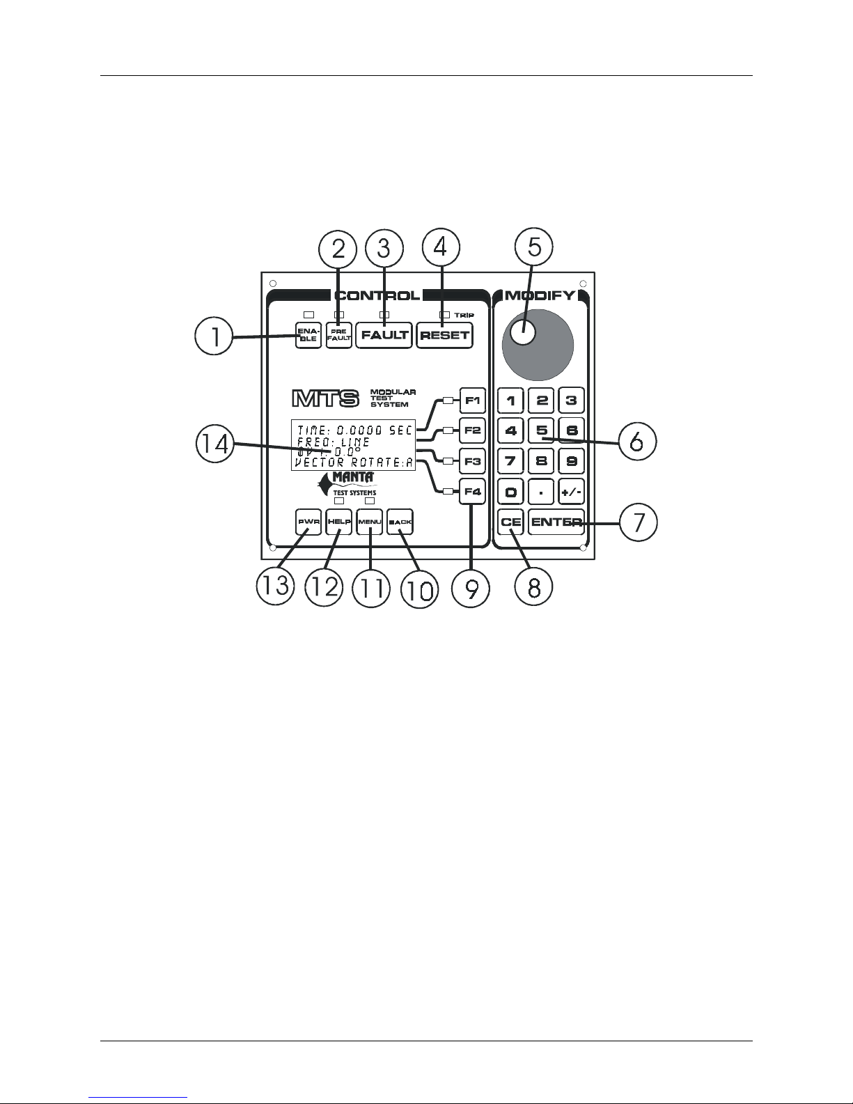
FIGURE 3.1 CONTROL MODULE PANEL
1. ENABLE PUSHBUTTON
This pushbutton enables the AC outputs. If the enable status LED isn’t lit, the outputs are disabled
and there will be no AC current or voltage available from the output terminals of the AC output
modules. This is defined as Programming mode.
When the outputs are e nabled by pressing this pushbutton, the enable status LED will light, as will
the output channel warning LEDs of all AC output module channe ls that are equipp ed with voltage
or current sources. This is define d as Test mode.
2. PREFAULT PUSHBUTTON
This pushbutton selects the Prefault state for off-line programming (ENABLE off) or toggles the
Prefault mode on or off (ENABLE on, Test mode). Current status is indicated by the PREFAULT
LED.
CU M004 01A
MTS-3000 SERIES OPERATION AND REFERENCE MANUAL 3-1
###################################0$1 7$#7( 67#6<67(06
Page 22

OPERATION SUMMARY - Section 3
•ON - System is in Programming mode, prefault state is selected.
•BLINKING - System is in Test mode, prefault state is selected and active.
•OFF - Either the system isn’t in PREFAULT state or Prefault mode isn’t selected.
3. FAULT PUSHBUTTON
This pushbutton selects Fault state for off-line programming (ENABLE off), or causes the MTS to
enter Fault state (ENABLE ON, Test mode).
Momentary operation (<250 msec.) of the pushbutton latches the MTS into Dynamic Fault state
until RESET is pressed or the Device Under Test (DUT) operates, as detected by an Input channel
on the DIGITAL I/O module. Sustained pressing of the pushbutton maintains the equipment in
Fault state only as long as it’s held depressed, and trip operations of a DUT will be annunciated,
but won’t trip off the outputs.
Current status is indicated by the FAULT LED
• ON - System is in Programming mode, FAULT is selected for programming
• BLINKING - System is in Test mode, FAULT is selected and active
• OFF - System is in either PREFAULT or POSTFAULT state
4. RESET PUSHBUTTON
This pushbutton is pressed to restore the system to Prefault state either following an operation of a
DUT (i.e. the system is in Postfault mode), or during a Fault sequence. It clears the timer reading
to zero while restoring any frozen AC output readings to normal.
When the TRIP LED above the RESET button is on, it indicates the system is in POSTFAULT
state as a result of a trip (DUT operation) during FAULT state.
5. MODIFY KNOB
This rotary knob can be used to make incremental changes to any currently selected parameter,
such as amplitude, phase, or frequency. Clockwise increases the value; counterclockwise decreases
it. Turning it faster makes larger coarser adjustments; slower makes smaller finer adjustments.
When performing data entry with the keypad, the knob is disabled until ENTER is pressed. The
knob is also used to scroll through menu items.
6. NUMERIC KEYPAD
These keys are used to enter numeric data, and to modify the currently selected parameter, such as
amplitude, phase, or frequency.
7. ENTER KEY
This key is used to signal the end of a numerical entry sequence, and to restore operation of the
MODIFY knob.
3-2 MTS-3000 SERIES OPERATION AND REFERENCE MANUAL
#0$17$#7(67#6<67(06###########################################
CU M004 01A
Page 23
OPERATION SUMMARY - Section 3
8. CANCEL ENTRY KEY
This key is pressed to clear all numbers just entered on the keypad. The BACK pushbutton (10)
will clear a single numeric entry. A second press of CE will restore the previously entered value.
9. FUNCTION KEYS
These keys are press ed to select or enable modification of a reading or parameter on the respec tive
line of the adjacent four-line liquid crystal display (LCD).
10. BACK PUSHBUTTON
This pushbutton is pressed to back up one level through the menu which appears on the display
above it, as well as to back up one key entry on the numeric keypad (6). Pressing it during normal
operation will force the display to menu mode and directly restore the user to the last menu option
accessed.
11. MENU PUSHBUTTON
Pressing this pushbutton toggles on or off an extensive menu which appears on the display above
it.
12. HELP PUSHBUTTON
Context sensitive help regarding operati on of many of the MTS system’s controls may be called up
by pressing this pushbutt on.
13. POWER PUSHBUTTON
This pushbutton turns on or off the mains power to the Control Module and to any AC output
modules connected to the Control Modul e.
14. ALPHANUMERIC DISPLAY
This Liquid Crystal Displa y (LCD) provides infor mation on current equ ipment status , and displa ys
numerous menu options.
CU M004 01A
MTS-3000 SERIES OPERATION AND REFERENCE MANUAL 3-3
###################################0$1 7$#7( 67#6<67(06
Page 24
OPERATION SUMMARY - Section 3
3.1.2 MTS-3010 Digital I/O Module
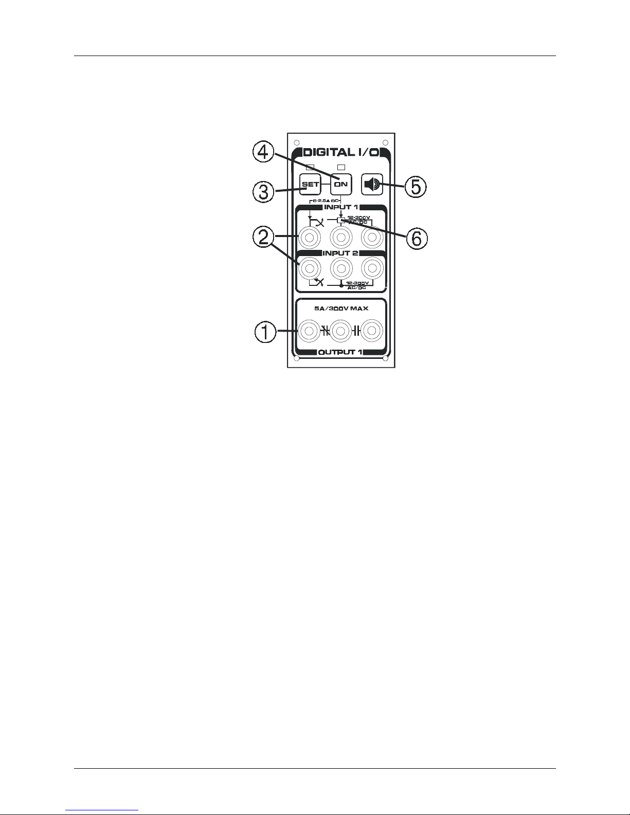
FIGURE 3.2 DIGITAL I/O PANEL
1. OUTPUT CONTACT TERMINALS
By default these contacts are configured, as indicated by the NC/NO symbols shown on the panel,
and contact changeover follows Fault mode status. Other modes are programmable via the menu.
2. INPUT SENSING TERMINALS
Operation of a Device Under Test (DUT) may be sensed by these inputs, either a dry or wet
contact operation, or a change in status of an AC/DC voltage. Debounce times on input sensing are
programmable. These high impedance inputs are galvanicly isolated from one another and from
the MTS system.
3. SET PUSHBUTTON
Selection of this pushbutton opens menu options on the Control Module display to allow
programming of options for the inputs and outputs, plus adjustment of the DC Current, if this latter
option is fitted.
4. ON PUSHBUTTON
This pushbutton toggles on or off the optional DC Current output to the two left terminals of Input
1. When DCI is enabled by this switch, whenever an external relay contact (in series with a DC
current operated target) closes, the programmed DC current will flow through the external circuit.
3-4 MTS-3000 SERIES OPERATION AND REFERENCE MANUAL
#0$17$#7(67#6<67(06###########################################
CU M004 01A
Page 25
5. TONE PUSHBUTTON
This pushbutton togg les on or off the audible indicator associated with the change of state det ector
circuits monitoring Input 1.
6. OPERATION SENSE LED
This LED illuminates if a change of contact state from NO to NC, or a change in voltage from off
to on, is sensed by Input 1. It’s particularly useful if the output contact of the relay being tested
cannot easily be observed, as is often the case with electronic relays.
3.1.3 MTS-3010 DC Voltage Source
OPERATION SUMMARY - Section 3
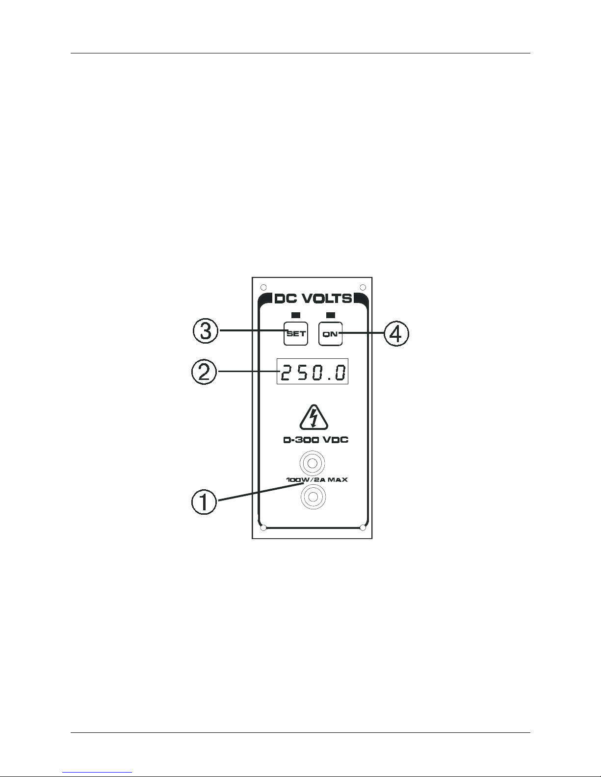
1. OUTPUT TERMINALS
Up to 300VDC at 100 W is available here.
2. DC VOLTAGE DISPLAY
The present setting of the DC voltage module is displayed on this LED display.
CU M004 01A
MTS-3000 SERIES OPERATION AND REFERENCE MANUAL 3-5
###################################0$1 7$#7( 67#6<67(06
FIGURE 3.3 DC VOLTAGE P ANEL
Page 26

OPERATION SUMMARY - Section 3
3. SET PUSHBUTTON
Pressing this pushbutton opens a menu on the main display of the Control Module to enable
adjustment of the DC voltage setting via the MODIFY keyboard and rotary knob.
4. ON PUSHBUTTON
This pushbutton toggles the output of the module on and off. Output On status is indicated by
illumination of the LED above the pushbutton.
3.1.4 MTS-3040 AC Voltage Module
Note: Features of the MTS-3060 AC Current and -3030 Voltage/Current modules are virtually
identical.
1. ALPHANUMERIC DISPLAY
This Liquid Crystal Display (LCD) provides information on current equipment status, including
amplitude and phase angle of each output source fitted to the unit.
2. FUNCTION KEYS
These keys are used to select a parameter prior to modifying it. The first press selects amplitude of
a given output, while the second selects its phase angle.
3. COOLING INTAKE/FILTER
The filter on this cooling intake may be removed for cleaning if necessary.
3-6 MTS-3000 SERIES OPERATION AND REFERENCE MANUAL
#0$17$#7(67#6<67(06###########################################
FIGURE 3.4 AC VOLTAGE PANEL
CU M004 01A
Page 27
4. OUTPUT STATUS LEDS
Illumination of these LEDs indicates that the outputs are enabled and capable of delivering energy
to a connect ed load, even if the output settings are presently at zero. If a module doesn’ t have a full
complement of output sources, only those outputs equipped with an output source will illuminate.
5. OUTPUT TERMINALS
Connection is made here to the device(s) under test.
3.2 REAR PANEL LAYOUT
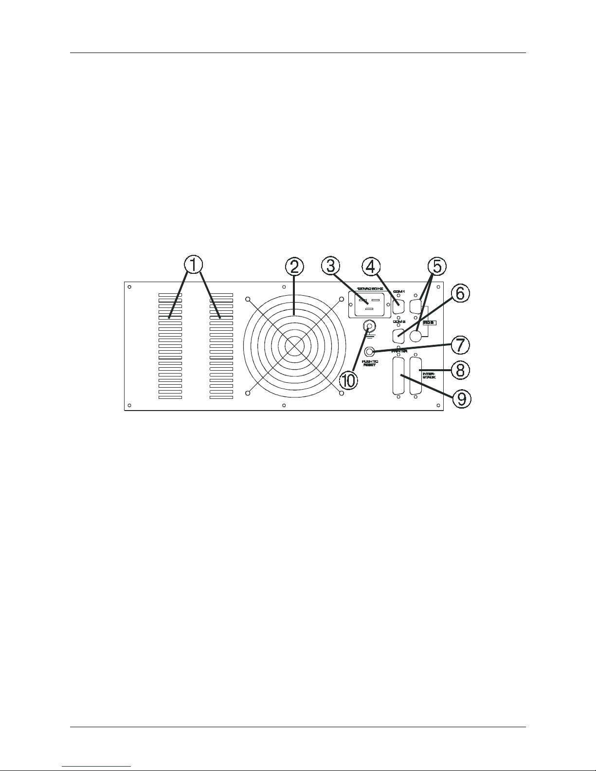
3.2.1 MTS-3 000 C o ntrol Mo du l e Re ar Panel
OPERATION SUMMARY - Section 3
FIGURE 3.5 CONTROL MODULE REAR PANEL
1. COOLING INTAKES
For adequate cooling, ensure that these are not obstructed.
2. COOLING EXHAUST
Ensure that warm air exiting isn’t restricted nor reflected back towa rds intakes.
3. AC INLET
For 120V or 240V main supply, as indicated by panel label.
4. COM 1 RS232C PORT
Female DB-9 serial port wired as a DCE (Data Communications Equipment) for external PC or
DUT.
5. IRIG B CONNECTORS (OPTIONAL)
Connect to IRIG B datastream from GPS receiver.
CU M004 01A
MTS-3000 SERIES OPERATION AND REFERENCE MANUAL 3-7
###################################0$1 7$#7( 67#6<67(06
Page 28

OPERATION SUMMARY - Section 3
6. COM 2 RS232C PORT
Male DB-9 serial port wired as a DTE (Data Terminal Equipment) for external PC.
7. MAINS CIRCUIT BREAKER
Press to reset if breaker trips.
8. EXTERNAL CONNECTOR
External I/O connector to run one or more systems in a master-slave configuration.
9. PRINTER PORT
Connects to external printer to print Quick-Test reports.
10. GROUNDING STUD
Connect to a secure external ground during testing.
3-8 MTS-3000 SERIES OPERATION AND REFERENCE MANUAL
#0$17$#7(67#6<67(06###########################################
CU M004 01A
Page 29
OPERATION SUMMARY - Section 3
3.3 BASIC APPLICAT IONS
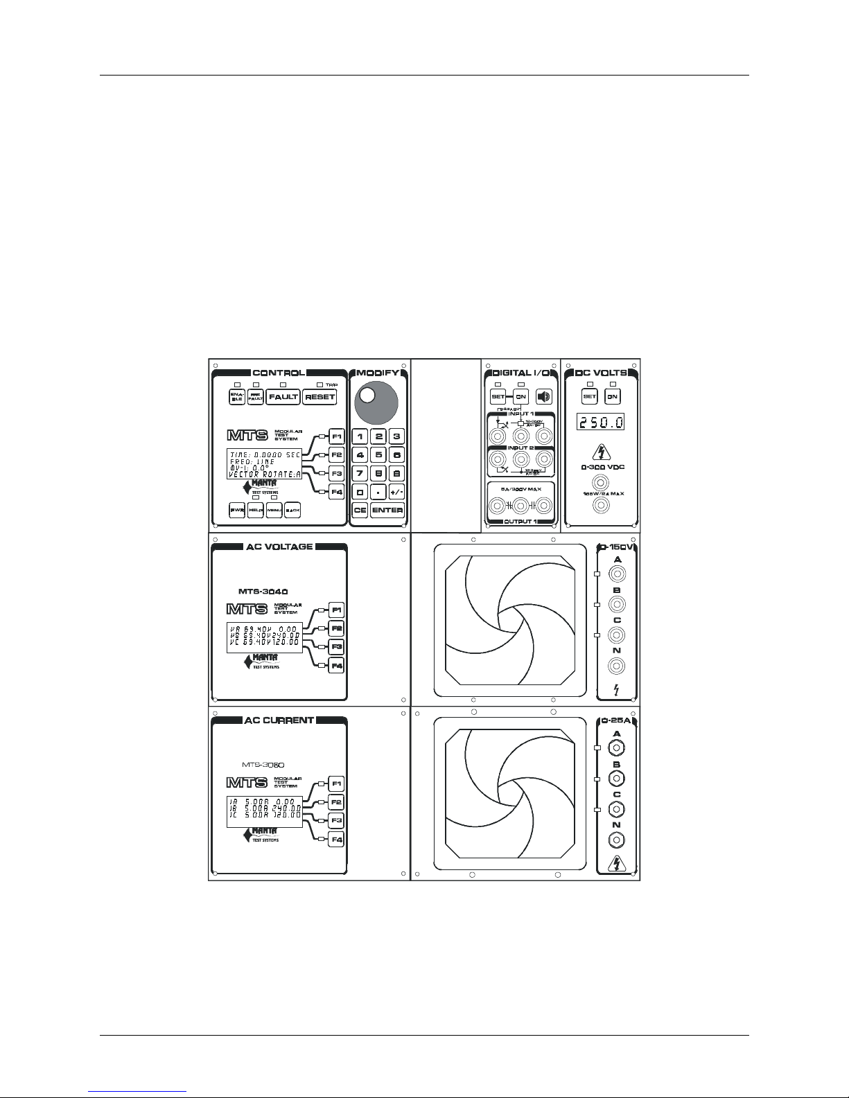
3.3.1 Getting Started
Because of its modularity, the MTS-3000 series system can be configured in many different ways. It’s not
feasible to provide a detailed operation description for every possible configuration. Except where noted,
the assumption is the equipment is configured as a three phase protective relay test system equipped with
three AC voltage sources, three AC current sources, a digital I/O module with DC current sourcing, and a
DC voltage module, as illustr ated below. Specific examples of less fully equipped syste ms will be provided
in the Detailed Operation section of this manual.
FIGURE 3.6 TYPICAL THREE PHASE SYSTEM
CU M004 01A
MTS-3000 SERIES OPERATION AND REFERENCE MANUAL 3-9
###################################0$1 7$#7( 67#6<67(06
Page 30
OPERATION SUMMARY - Section 3
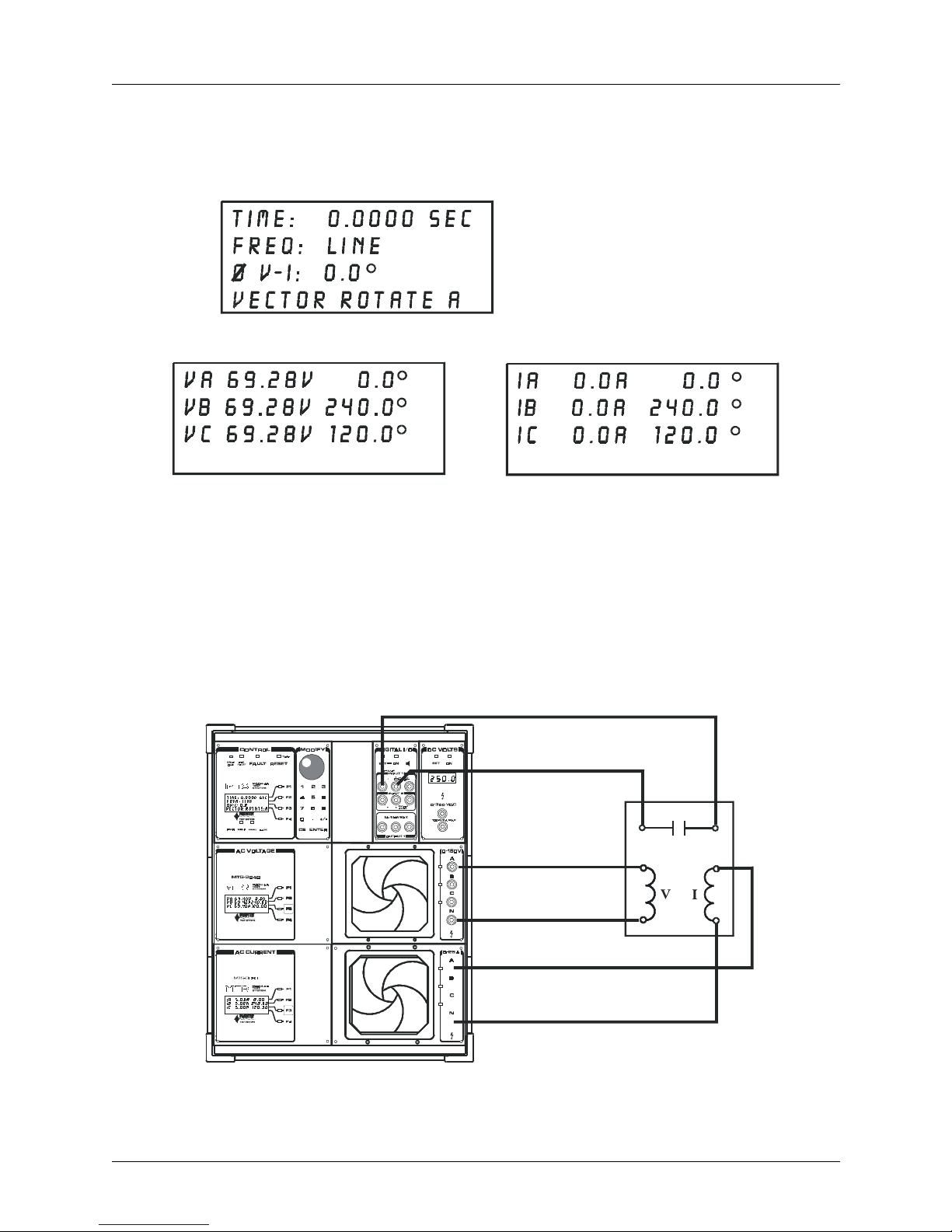
Connect mains power to the Control Module (CM), the rear panel chassis safety ground to a known good
ground, and press PWR. A momentary message, indicating software version number and other
information, appears briefly on the CM display. LEDs are turned on briefly, and then the default displays
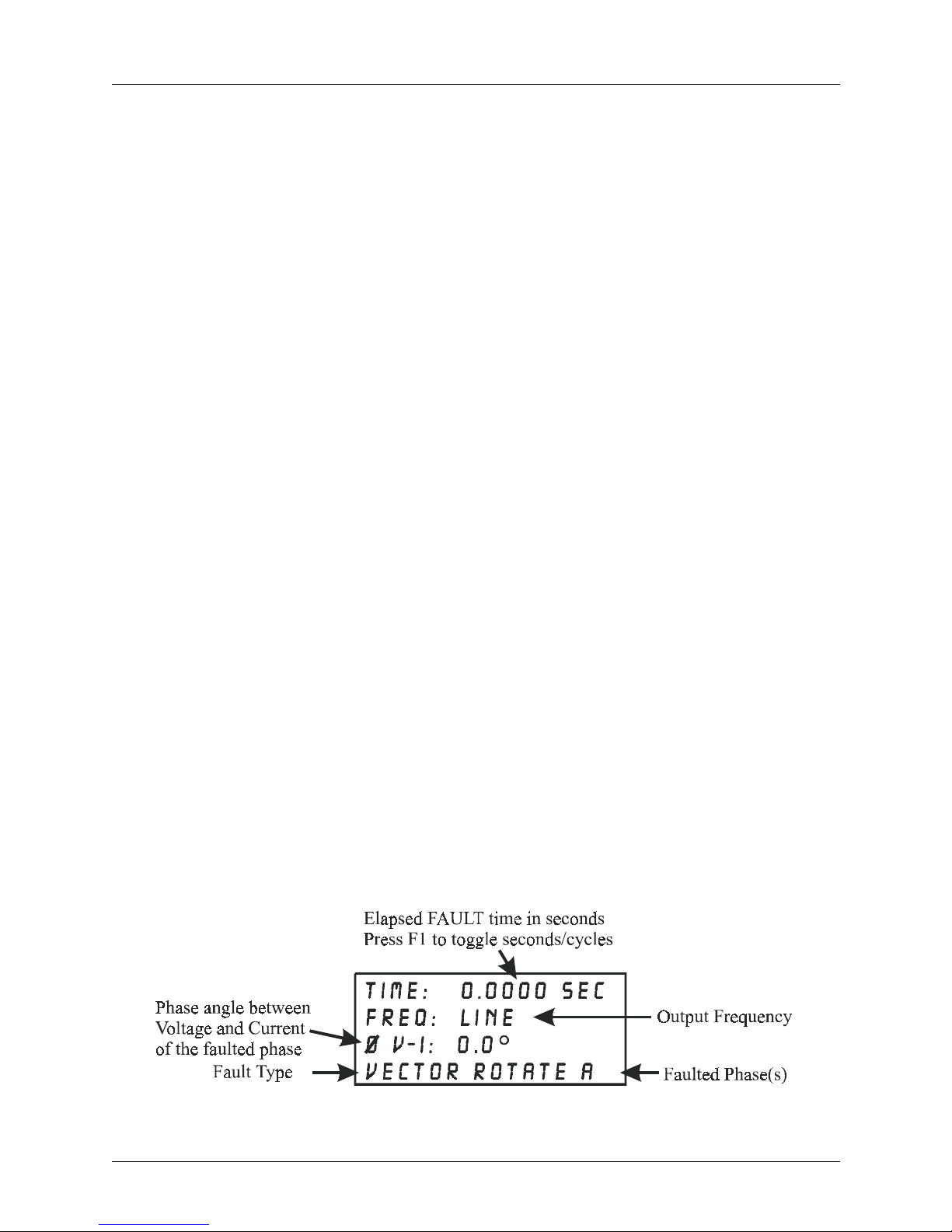
will appear as shown below:
The voltage and current modules will show default values as shown respectively below:
FIGURE 3.7
DISPLAY MESSAGES
These values correspond to a balanced three-phase voltage of 120V phase-to-phase, and current which will
be in phase with the voltage. If an output module isn’t fitted with a full complement of output sources,
there will be less data on the display(s). If the current output module, for example, has only two current
sources, only lines IA and IB will appear on the display.
The example that follows illustrates some of the important operating aspects of the system. It’s assumed
that a single phase impedance relay with a time delay response is connected to the MTS-3000 system,
operating at approximately 50 volts and seven amps, with a phase shift between voltage and current of 75°.
3-10 MTS-3000 SERIES OPERATION AND REFERENCE MANUAL
#0$17$#7(67#6<67(06###########################################
FIGURE 3.8
TEST CONNECTIONS
CU M004 01A
Page 31

OPERATION SUMMARY - Section 3
The voltage coil is conne cted to AC voltage terminals A and N, the current coil to AC current terminals A
and N, and the relay output contact to INPUT 1 terminals of the DIGITAL I/O module. If it’s desired to
follow through the steps of the test process using your MTS system, a short jumper cord with male banana
terminals can be inserted into the two left terminals of INPUT 1 at the appropriate times to simulate relay
operation. It will be necessary to provide a current path by shorting terminals A and N of the current
module with a second jumper cord.
CU M004 01A
MTS-3000 SERIES OPERATION AND REFERENCE MANUAL 3-11
###################################0$1 7$#7( 67#6<67(06
Page 32

OPERATION SUMMARY - Section 3
3.3.2 Basic AC Voltage, Current and Phase Angle Output
1.Ensure the system outputs are disabled. Press
ENABLE, if necessary, to extinguish its LED. Select
FAULT mode by pressing FAULT. The FAULT LED
lights to confirm the selection.
2. Press F1 of the voltage module. Its LED lights to
indicate selection of channel VA, and a flashing cursor
appears beneath the V on the first line of the adjacent
display.
3.Press 5, 0,., 0, and ENTER on the MODIFY keypad.
Channel VA amplitude reading follows the typed input
and changes to 50.00 V.
4.Press F1 on the current module. Its LED lights to
indicate selection of channel IA, and a flashing cursor
appears beneath the A on the first line of the adjacent
display. The LED on channel VA goes out.
5.Press 7,
Channel IA amplitude reading follows the typed input
and changes to 7.00A.
6.Press F1 again on the current module. Its LED remains
lit, and a flashing cursor appears beneath the degree
symbol (
7.Press 7, 5,
Channel IA phase angle reading follows the typed
input and changes to 75.0
FIGURE 3.9 BASIC AC ADJUSTMENTS phase angle reading on the CM display also changes to
75.0
8.Press ENABLE. The ENABLE LED lights.
9.Press and hold FAULT. The FAULT LED flashes to indicate fault state is active. The output warning
LEDS next to the output terminals of the current and voltage modules are also lit, indicating that the
outputs are enabled. The programmed (and other default) AC voltage and current values appear at the
outputs until the FAULT button is released.
, 0, 0, and ENTER on the MODIFY keypad.
.
°) on the ‘IA’ line of the display.
, 0, and ENTER on the MODIFY keypad.
.
°. The voltage-to-current
°.
If the programmed values in the example above were sufficient to operate the relay connected to the
outputs of the MTS system, then, upon operation of the relay the LED indicator associated with INPUT 1
will light, and the audible tone will sound. Once the FAULT button is released, the AC outputs return to
zero, the relay being tested drops out, and the indicator LED and tone turn off.
3-12 MTS-3000 SERIES OPERATION AND REFERENCE MANUAL
#0$17$#7(67#6<67(06###########################################
CU M004 01A
Page 33

OPERATION SUMMARY - Section 3
If the chosen AC values were close to the relay operate point - but did not pick it up - the MODIFY knob
can be used to continuously vary one parameter until the pickup point is determined. Consider, for
example, that the voltage and phase angles were appropriate, but the current was too low.
10. Reselect IA current amplitude adjust mode by pressing F1 on the current module. Note that the initial
press selects amplitude adjust mode, the second press phase angle adjust mode, the third press
deselects that channe l (LED will go out), and the fourth press selects amplitude adjust mode again.
11. Press and hold the FAULT button, and rotate the MODIFY knob slowly cloc kwise until the relay being
tested operates, as ver ified by the DIGIT AL I/O visual (LED) and audible indicators.
12. If it’s desired to verify the operate point more precisely, the MODIFY knob is rotated
counterclockwise and clockwise, as required, to lower and raise respectively the output current
through the operate point.
Now consider that a timing check is to be done on the relay under test at a current well above the operate
point. For this example, it will be assumed that the relay minimum pickup occurred at 7.00 amp s a nd th e
timing check is to be performed at 10.00 amps.
13. Disable the outputs by pressing ENABLE. The ENABLE LED and the AC output warning LEDs will
go off. This permits the readjustment of current amplitude to be done ‘off line’.
14. Press FAULT. I ts status LED will light.
15. Reselect IA current amplitude adjust mode by pressing F1 on the current module. Press 1, 0,
., 0, and
ENTER on the MODIFY keypad. This new value appears in the IA channel display.
16. Press ENABLE to re-enable the AC outputs. The ENABLE LED lights.
17. Press the FAULT button briefly only. This automatically latches the system into Dynamic Fault mode,
the FAULT LED begins to flash slowly to indicat e the FAUL T mode is active, and the timer reading in
the first line of the Control Module display begins incrementing. The AC output warning LEDs light,
and the programmed AC values appear at the AC output terminals.
18. When the relay operates, it trips off the AC outputs of the MTS, freezes the timer a nd AC output
readings, and enters the ‘Post Fault’ state, as indicated by extinguishing of the FAULT LED and
illumination of the TRIP LED located above the RESET pushbutton.
19. Once the timing results have been observed and, if necessary, recorded, the system is returned to
normal by pressing RESET. This resets the timer and V/I readings, and extinguishes the TRIP LED.
Note the important difference in this ‘dynamic fault’ mode compared to the ‘static fault’ mode described in
steps 1-12.
CU M004 01A
MTS-3000 SERIES OPERATION AND REFERENCE MANUAL 3-13
###################################0$1 7$#7( 67#6<67(06
Page 34

OPERATION SUMMARY - Section 3
STATIC FAULT MODE
When the FAULT button is pressed and held, the system is in static fault mode. The AC outputs stay
energized as long as the FAULT button is held on, and the appearance of a trip signal at the DIGITAL I/O
module INPUT 1 will annunciate, but won’t trip off the AC outputs.
DYNAMIC FAULT MODE
A brief (<250 msec.) press on the FAULT button latches the system into dynamic fault mode. In this mode,
the AC outputs latch on until terminated by either pressing RESET or by appearance of a trip signal from
the relay under test, as monitored by INPUT 1 of the DIGITAL I/O module.
Typically, static test mode is used for accurate determination of pickup points, where it’s desired to swing
AC outputs repeatedly through the operate point without interrupting the outputs. Dynamic test mode is
usually used for timing checks, especially at higher current levels where it’s desirable to minimize the time
the current is applied to the device under test.
3.3.3 Frequency Output
By default, all AC outputs are synchronized to the input line frequency. Variable frequency mode can
generate one or two different frequencies for each fault state in the range of 8 to 1000Hz. Any output or
combination of outputs can be assigned to either of the frequency sources.
3.3.3.1 BASIC FREQUENCY OUTPUT.
Basic frequency mode allows one or more channels to be selected to output a frequency (Frq1) in the range
of 8 - 1000Hz. All other output channels will remain at the default "LINE" frequency. Frequency 1 (Frq1)
can be set to different frequencies for prefault and fault state, if desired.
1.Select the desired fault state - either prefault or
fault.
2.Press F2 in the MODIFY section of the CM. This
enables frequency adjust mode, the LED lights,
and the second and third lines of the display
change, as shown.
3.Enter the desired new frequency via the MODIFY
numeric keypad followed by ENTER, or by turning the rotary knob until the desired frequency is
shown on the second line of the display.
4. Individual output channels now may be assigned
this frequency by pressing their Fn keys. The
associated channel LEDs will flash to indicate
they’ve been set to the new frequency. A second
press of any Fn key will restore that channel to the
default line frequency. Deselecting F2 on the CM
by pressing it again locks all previously assigned
(flashing) channels to Frequency 1, disables the
MODIFY input, turns off the F2 LED, and returns
the display to normal.
FIGURE 3.10 FREQUENCY ADJUST
3-14 MTS-3000 SERIES OPERATION AND REFERENCE MANUAL
#0$17$#7(67#6<67(06###########################################
CU M004 01A
Page 35

OPERATION SUMMARY - Section 3
5. To return to the default (all output channels synchronized to LINE), press F2, followed by F3 on the
CM. F3 selects the SEL[ect] LINE SYNC mode, and disables the frequenc y adjust mode.
To display the output frequency of any channel, first ensure the frequency programming mode is disabled
(i.e. the F2 LED on the CM should be extinguished). Then select the channel by pressing its Fn key. The
frequency of the particular output channel will appear on line 2 of the CM display.
3.3.3.2 ADVANCED FREQUENCY OUTPUT.
Advanced frequency mode is an exte nsion of basic frequency mode in that unsel ected output channels will
be set to frequency 2 (Frq2) instead of "LINE". To set frequency 2:
Enter the follo wing key sequence: MENU | Settings | Fr equency 2 | Internal, and the n press F3 to enter the
desired Frequency 2 value.
3.3.4 DC Voltage
In basic DC voltage mode, the dc output voltage is independent of fault state. Advanced dc voltage mode
allows the user to set different DC voltage levels in each of the prefault, fault, and postfault states.
3.3.4.1 BASIC DC VOLTAGE OUTPUT.
FIGURE 3.11 DC VOLTAGE ADJUST
1. Press SET on the DC
VOLTS module. The
SET LED will tur n on,
and the display in the
CONTROL section of
the CM will c hange, as
shown.
2. Press F1 on the CM.
This enables Modify,
activates a flashing
cursor on the F1 line of
the display, and turns
on the F1 LED to
indicate DC volts
adjust mode is active.
3. Ent er the desired DC voltage level on the MODIFY keyboard. For 250.0VDC, for example, press 2, 5,
0, ENTER. This setting will appear on line 1 of the CM display, as well as the LED output display of
the DC VOLTS module.
CU M004 01A
MTS-3000 SERIES OPERATION AND REFERENCE MANUAL 3-15
###################################0$1 7$#7( 67#6<67(06
Page 36

OPERATION SUMMARY - Section 3
4.Incremental changes to the setting can be made with the MODIFY rotary knob. When finished, disable
Modify by pressing SET again. This will extinguish the SET LED and the F1 LED, and restore
previously existing readings to the CONTROL display.
5. To apply the DC voltage to a connected load, press the ON switch on the DC VOLTS module. This
connects the programmed DC to the output terminals and lights the ON LED status indicator,
regardless of the status of the AC outputs.
3.3.4.2 ADVANCED DC VOLTAGE OUTPUT.
Advanced dc voltage mode allows the user to set different DC voltage levels for each of the prefault, fault,
and postfault states.
1. Press SET on the DC VOLTS module. The SET LED will turn on, and the display in the CONTROL
section of the CM will change, as shown.
2.Press F2 on the CM to set enable fault state specific voltage levels
3. Select F1, F2, or F3 to program the Prefault, Fault, or Postfault levels respectively.
3.3.5 DC Current Output
This optional feature is for testing DC current operated targets on older electromechanical relays. These
targets are typically connected in series with the relay trip output contact so the MTS contact sensing
INPUT 1 is used to supply DC current to the external relay output circuit.
NOTE: The low impedance nature of this source could provide the necessary trip path to inadvertently trip
an auxillary relay or circuit breaker. The DC current output only should be used when the
protective relays trip output circuit is properly isolated.
3-16 MTS-3000 SERIES OPERATION AND REFERENCE MANUAL
#0$17$#7(67#6<67(06###########################################
FIGURE 3.12 DC CURRENT ADJUST
CU M004 01A
Page 37

OPERATION SUMMARY - Section 3
1. Press SET on the DIGITAL I/O module. The SET LED lights and the display in the CONTROL
section of the CM changes, as shown.
2. Press F3 on the CM. This enables Modify, activates a flashing cursor on the F3 line of the display, and
turns on the F3 LED to indicate DC current adjust mode is active.
3. Ent er the DC current level ( typically 0. 2 or 2.0 amps) on the MODIFY keyboard, followed by ENTER,
or turn the MODIFY rotary knob until the desired reading appears on the F3 line of the display.
4. Disable Modify by pressing SET again. This will extinguish the SET LED and restore previously
existing readings to the CONTROL display.
5. Apply the programmed DC current output to a circuit connected to the two left hand terminals of
INPUT 1 at any time by pressing the ON switch on the DIGITAL I/O module. The ON LED indicates
the status of this output. The DC output may be left on continuously so it immediately operates the
target of any rela y under te st upon relay pickup.
Note that pressing the SET button on the DIGITA L I/O module also provides access to the advanced input
and output settings of the DIGITAL I/O module. Further information on these features is available in the
Advanced Operation sect ion of thi s manual.
3.3.6 High AC Voltage Output
The standard output of 150 V phase to neutral available from each AC output source is adequate for most
protective relaying applications, but occasionally higher voltages may be required. If at least two voltage
sources are fitted, it’s possible to obtain higher voltages by modifying the phase relationship of the
voltages.
C
Bb
N
A
Load
B
FIGURE 3.13
AC VOLTAGE VECTORS
As shown in the diagram, the output load is normally connected phase to neutral, in this case A to N. For
voltage requirements greater than 150 volts, the load may be connected between A and Bb. It’s necessary
to adjust the phase angle of phase B voltage from its default 240.0
° to 180.0°. The resultant voltage will
then be the mathematical sum of the amplitudes of the two voltages.
CU M004 01A
MTS-3000 SERIES OPERATION AND REFERENCE MANUAL 3-17
###################################0$1 7$#7( 67#6<67(06
Page 38

OPERATION SUMMARY - Section 3
3.3.7 High AC Current Output
It’s relatively common to require higher current than can be delivered by a single current output channel.
The current channels may be paralleled to increase total current but, as shown, it’s necessary to modify the
phase angle of each channel that’s added in parallel to the initial one. The amplitude of each channel also
should be set to the same value.
C
Cc
N
A
Bb
B
Load
FIGURE 3.14
AC CURRENT VECTORS
Two or three output channels may be paralleled at the output terminals, or at the connected load. It’s
important to use the largest feasible current leads to minimize voltage drop in the leads, especially if the
leads are paralleled at the load and only a single neutral lead returns the current to the source.
TIP: There’s a menu selection available to automatically adjust all available sources for optimum high
current delivery, as well as to provide a direct reading of the total current. See Parallel Current
Mode in the Advanced Operation section.
3.3.8 Overcurrent Relay Test
FIGURE 3.15
3-18 MTS-3000 SERIES OPERATION AND REFERENCE MANUAL
#0$17$#7(67#6<67(06###########################################
OVERCURRENT RELAY TEST
CU M004 01A
Page 39

OPERATION SUMMARY - Section 3
3.3.8.1 SETUP.
To test a single phase overcurrent relay, connect the test leads, as shown by the solid lines. A three-phase
relay or three single-phase devices on a relay panel require the additional connections shown as dashed
lines.
If the relay requires auxiliary DC power, connect it as shown by the dotted lines. If there are more than a
single set of contacts provided (e.g. separate timed and instantaneous contacts), it will be necessary to
move the contact operation se nsing leads to the appropriate termina ls for the separate element tests. If three
current modules are not fi tted, it will be necessa ry to move the Ia output to the other phase s in turn to verify
them.
The system should be in Vector fault mode, as shown in the fourth line of the CM display a bove. If it isn’t,
enter the following ke y sequ ence: MENU | Settings | Fault T ype | Vector, and then press MENU again.
3.3.8.2 MINIMUM PICKUP TEST
.
1. Disable the outputs, if necessary, by pressing ENABLE until its LED is out, and press FAULT. Its
LED should come on.
2. Select the A phase of the current output module by pressing the F1 key on the module. Its LED will
come on and a cursor will flash slowly beneath the ‘A’ representing Amps in the F1 line of the
module’s display.
3. Enter (via the MODIFY keyboard or rotary knob), a current value that’s somewhat less than the
expected minimum pickup level of the relay under test.
4. Enable the outputs by pressing ENABLE. Press and hold FAULT, and rotate the MODIFY knob
clockwise until the relay begins to operate. The LED indicator on INPUT 1 of the DIGITAL I/O
module will light, and the audible tone, if enabled via the tone switch, will sound. The current may be
adjusted up or down via the MODIFY knob to verify the pickup level.
5. Release the FAULT button when the test is complete.
TIP: INPUT 2 on the DIGITAL I/O module can be configured as an external start input to work with a
foot switch, relieving the operator of the need to continuously press the FAULT pushbutton. See
the Advanced Operation section for information on configuring the input. Any commercial
normally open foot switch will work. A heavy duty one is available from Manta Test Systems.
3.3.8.3 INVERSE-TIME CHARACTERISTIC TEST.
If the expected current required for this test is higher than can be achieved from a single current output
channel, it will be necessary to parallel two or three channels to get the desired current. Use the heaviest
gage leads possible to minimize voltage drop in the leads. If the output channels are paralleled at the load
instead of at the output terminals, remember that the neutral lead will be carrying two o r three times the
current of the individual phase leads. Ensure that the amplitudes and phase angles of each channel are
adjusted correctly (as described in previous item 3.3.7), or use the automated paralleling feature available
through the Control Module’s menu.
CU M004 01A
MTS-3000 SERIES OPERATION AND REFERENCE MANUAL 3-19
###################################0$1 7$#7( 67#6<67(06
Page 40

OPERATION SUMMARY - Section 3
Disable the outputs, if necessary, by pressing ENABLE until its LED is out, and press FAULT. Its LED
1.
should come on.
2.Select the A phase of the current output module by pressing the F1 key on the module. Its LED will
come on and a cursor will flash slowly beneath the ‘A’ representing Amps in the F1 line of the
module’s display.
3.Enter (via the MODIFY keyboard or rotary knob) the first current level at which a timing check is to
be made on the relay under test.
4.Enable the outputs by pressing ENABLE. Press FAULT momentarily and release it. The Fault current
will seal in and stay on until the relay operates. At that time, the FAULT LED will stop its slow
flashing, the TRIP LED will light, the output current will trip off, and the timer and all current, voltage,
and phase readings will be frozen.
5.Record the current and timer readings, and press RESET to restore the system to Prefault mode.
6. Repeat Steps 1 through 5, as required, for each new value of current.
3.3.8.4 INSTANTANEOUS ELEMENT TEST.
In many cases, it will be necessary to parallel current channels to reach the high current settings often
applied to instantaneous elements. See the previous test for further details. Many relays have a separate
output contact for the instantaneous element; so it may be necessary to move the relay operation sensing
leads of INPUT 1.
1.Disable the outputs, if necessary, by pressing ENABLE until its LED is out, and press FAULT. Its LED
should come on.
2.Select the A phase of the current output module by pressing the F1 key on the module. Its LED will
come on and a cursor will flash slowly beneath the ‘A’ representing Amps in the F1 line of the
module’s display.
3.Enter (via the MODIFY keyboard or rotary knob) a current level within 5%, but lower than the
expected operate point of the relay under test.
4.Enable the outputs by pressing ENABLE. Press and hold FAULT. Raise the current with the MODIFY
knob until the relay operates.
5.Release the FAULT button. This will reset the timer, and the current programming will remain at the
level it was when the relay operated.
6.Press the FAULT button briefly and release. The relay should operate again with the current applied
dynamically. The TRIP LED will light, the output current will trip off, and the timer and all current,
voltage, and phase readings will be frozen.
Record the current and timer readings, and press RESET to restore the system to Prefault mode.
3-20 MTS-3000 SERIES OPERATION AND REFERENCE MANUAL
#0$17$#7(67#6<67(06###########################################
CU M004 01A
Page 41

OPERATION SUMMARY - Section 3
TIP: If the tests are being conducted on a three phase relay, three current sources are fitted, and the test
being done can be handled by a single channel. Press F4 on the CM to transfer the test settings to
the next phase.
3.3.8.5 TARGET/SEAL-IN TEST.
If the rela y under test has a DC current-operated ta r get, the sensing leads from INPUT 1 must be connected
to the contact out put terminals of the relay which c ontain the target element. Note that the DC current is an
optional feature of the DIGITAL I/O module.
1. As des cribed in the above se cti ons, program the AC curr ent with outputs disabled to a sufficien tly high
level to ensure operation of the element under test.
2. As described in item 3.3.5 DC Current Output, program the DC current to an appropriate level for the
relay under test. The most common levels are 0.2A and 2.0A. Since this isn’t a precision pickup test
and is only designed to verify that the target will operate when tripping current passes through the trip
contact, it’s suggested that the setting be 5% to 10% above the nominal level.
3. Press the ON button on the DIGITAL I/O module. This enables the DC current output and turns on its
status indicator LED. Press ENABLE in the Control section of the CM to enable the AC outputs.
4. Pr ess FAULT momentarily to la tch on the AC outputs. When the AC current ele ment of the relay under
test closes its contact, the DC curr ent passing through the con tact will pick up the DC target. The TRIP
LED in the CONTROL section will light, and the AC current to the relay will turn off. The operation
indicator LED on I NPUT 1 should stay on, as will the audible tone indicator if selected to on, si nce the
auxiliary contac ts of the target relay in parallel with the AC contact remain picked up.
5. Press the ON pushbutton of t he DIGITAL I/O module to turn off the DC current. This will drop out the
seal-in relay, as indicated by the INPUT 1 LED and tone turning off.
CU M004 01A
MTS-3000 SERIES OPERATION AND REFERENCE MANUAL 3-21
###################################0$1 7$#7( 67#6<67(06
Page 42

OPERATION SUMMARY - Section 3
3.3.9 Differential Relay - Three Terminal Type
Most Electromechanical current differential relays are a three terminal type. This section describes how to
perform tests on this type of relay.
FIGURE 3.16 THREE TERMINAL DIFFERENTIAL RELAY TEST
3.3.9.1 PICKUP TEST.
Connect the relay as shown above. Connections are also shown for DC voltage supply to the relay if it
requires auxiliary power.
1.Select slope display mode by entering the following key sequence: MENU | Settings | Display Optns |
Slope | 3wdg BDD style, followed by MENU again.
Selecting slope display mode forces the CM to display the % slope, operate current, and restraint current
on the 2nd and 3rd line of the CM. The phase angle of Ib also will change to 180
°.
2.Disable the outputs if necessary by pressing ENABLE until its LED is out, and press FAULT. Its LED
will come on.
3.Select the A phase of the current output module by pressing the F1 key on the module. Its LED will
come on and a cursor will flash slowly beneath the ‘A’ representing Amps in the F1 line of the
module’s display.
4.Enter the desired restraint current via the MODIFY keyboard or rotary knob.
5.Select the B phase of the current output module by pressing the F2 key on the module, and enter the
desired restraint current via the MODIFY keyboard or rotary knob.
6.Enable the outputs by pressing ENABLE. Press and hold FAULT.
3-22 MTS-3000 SERIES OPERATION AND REFERENCE MANUAL
#0$17$#7(67#6<67(06###########################################
CU M004 01A
Page 43

OPERATION SUMMARY - Section 3
7. Press F1 on the current module to select the A phase current for amplitude adjustment and rotate the
MODIFY knob clockwise until the relay begins to operate. The LED indicator on INPUT 1 of the
DIGITAL I/O module will light, and the audible tone if enabled via the tone switch, will sound. The
current may be adjusted up or down via the MODIFY knob to verify the pickup level.
The calculated values of slope, operate current and restraint current are displayed on the 2nd and 3rd
line of the CM display.
8. Release the FAULT button when the test is complete.
9. To repeat for different values of restraint current, repeat the above process.
3.3.9.2 OPERATE TIME TEST.
1. Set up the MTS, as described above, with operate current sufficient to operate the relay at the desired
level of restraint cu rre nt.
2. Clear any previous trip indications by pressing RESET. Press FAULT momentarily to enter Dynamic
Fault Mode. The AC outputs will be latch ed on until the relay opera tes. The TRIP signal will force the
transition from FAULT to POSTFAULT, illuminating the TRIP LED, freezing the timer and AC
readings, and disabling the AC outputs.
3. Record the timer reading from the first line on the Control Module di splay, and press RESET to rest ore
the system operation.
3.3.9.3 HARMONIC RESTRAINT TEST.
1. Disable the AC outputs with the ENABLE switch. Remove the lead from channel B since it isn’t
required for this test.
2. Pr ess the FAULT button to se lect FAULT state.
3. Select channel A amplitude of the current module, and adjust it with the MODIFY knob or keypad to
the desired test value (us ual ly equal to the tap value).
4. Select channel B amplitude of the current module, and adjust it to 0 with MODIFY knob or keypad.
5. Enable the outputs by pressing the ENABLE button.
6. Select Harmonic mode for current channel A via the CM menu by entering the following key
sequence: MENU | Settings | Harmonics | ACI1
φA
Harm | Fund+Harm | Ampl 0.0 %. This enables
MODIFY to directly adjust the percentage of harmonic content of the fundamental current whose
amplitude is displayed on the AC current module.
Note the display for IA changes from IA to IAh as a reminder that IA is in harmonic mode.
CU M004 01A
MTS-3000 SERIES OPERATION AND REFERENCE MANUAL 3-23
###################################0$1 7$#7( 67#6<67(06
Page 44

OPERATION SUMMARY - Section 3
7.Press and hold FAULT. The relay should pick up.
8.While holding the FAULT button, Press F3 to select "Ampl 0.0 %"
9.Rotate the Modify knob clockwise while continuing to press FAULT. The % harmonic content of the
AC current will continue to increase, as observed on the display of the CM, until the relay drops out.
Record the % harmonic reading at this point.
10.Disable harmonic mode before proceeding with other tests. Press the BACK key, followed by:
Harmonics OFF, and then press the MENU button to exit the menu system.
Note that, for some latching trip elements, it may be necessary to reverse the order of this sequence (i.e.
initially set the % harmonic content to a high level, and then lower it until the relay picks up).
3.3.9.4 INSTANTANEOUS TEST.
1.Disable the AC outputs with the ENABLE switch.
2.Channel B should still be disconnected from the relay as in the previous section. If more current is
required in this step than can be delivered by a single channel, parallel the required number of channels
(See Parallel Current Mode in the Advanced Operation section).
3.Select the output channel(s) amplitude adjust mode and, with MODIFY keypad or rotary knob, set a
current to be within 5%, but lower than the expected operate point.
4.Enable the AC outputs by pressing the ENABLE button. Press and hold FAULT. Increase the current
output with the MODIFY rotary knob until the relay operates, note the current at that point, and release
FAULT.
5.The operate point can be checked dynamically by leaving the current amplitude adjustment at the same
point, and by pressing FAULT briefly only. This will latch on the current until it’s tripped by sensing
the relay operation. After recording the operate value, press RESET to restore normal operation.
3.3.9.5 TARGET TEST.
If the relay under test has a DC current-operated target, the sensing leads from INPUT 1 must be connected
to the contact output terminals of the relay which contain the target element. Note that the accompanying
differential relay drawing doesn’t show the current target coil and contact, and the DC current capability is
an optional feature of the DIGITAL I/O module.
1.As described in the above sections, program the AC current with outputs disabled to a sufficiently high
level to ensure operation of the element under test.
2.As described in section 3.35 DC Current Output, program the DC current to an appropriate level for
the relay under test. The most common levels are 0.2A and 2.0A.
3.Press the ON button on the DIGITAL I/O module, which enables the DC current output and turns on
its LED.
3-24 MTS-3000 SERIES OPERATION AND REFERENCE MANUAL
#0$17$#7(67#6<67(06###########################################
CU M004 01A
Page 45

OPERATION SUMMARY - Section 3
4. Enable the AC outputs by pressing the ENABLE button in the Control section of the CM.
5. Press FAULT momentarily to enter Dynamic Fault Mode. When the AC current element of the relay
under test closes its contact, the DC current passing through the contact will pick up the DC target and
force the transition from FAULT to POSTFAULT. The TRIP LED in the CONTROL section will light,
and the AC current to the relay will tur n off. The operation indicator LED on INPUT 1 should sta y on,
as will the audible tone indicator if selected to on, since the auxiliary contacts of the target relay in
parallel with the AC contact remain picked up.
6. Pr ess the ON pushbutton of the DIGI TAL I/O module to turn of f the DC current. This will drop out the
seal-in relay, as indicated by the INPUT 1 LED and tone turning off.
3.3.10 Different ial Relay - Independent Coil T ype
Many solid state current differential relays hav e independent coils for the two current inputs. This section
describes how to perform standard tests on this type of relay.
FIGURE 3.17 INDEPENDENT COIL DIFFERENTIAL RELAY TEST
3.3.10.1 SLOPE TEST.
Connect the relay, as shown above. The dotted connection between A and C channel outputs may be used
if slope checks are to be done at very high current levels. Connections are also shown for DC voltage
supply to the relay if it requir es auxiliary power.
1. Select slope display mode by entering the following key sequence: MENU | Settings | Display Optns |
Slope | 2wdg 87T style, followed by MENU again.
CU M004 01A
MTS-3000 SERIES OPERATION AND REFERENCE MANUAL 3-25
###################################0$1 7$#7( 67#6<67(06
Page 46

OPERATION SUMMARY - Section 3
Selecting slope display mode forces the CM to display the % slope, operate current, and restraint current
on the second and third line of the CM. The phase angle of Ib also will change to 0
°.
2.Disable the outputs, if necessary, by pressing ENABLE until its LED is out, and press FAULT. Its LED
will come on.
3.Select the A phase of the current output module by pressing the F1 key on the module. Its LED will
come on and a cursor will flash slowly beneath the ‘A’ representing Amps in the F1 line of the
module’s display.
4.Enter the desired nominal Ia (restraint) current via the MODIFY keypad or rotary knob.
5.Select the B phase of the current output module by pressing the F2 key on the module, and enter the
desired nominal restraint current via the MODIFY keyboard or rotary knob.
6.Press the F2 key of the current module again to select phase angle adjustment on B phase, indicated by
a flashing cursor beneath the
° symbol.
7.Adjust the phase angle on channel B, as required, via the MODIFY keyboard or rotary knob. The angle
is usually set to 0
°, but may be displaced by +/- 30( for relays protecting wye-delta transformers.
8.Enable the outputs by pressing ENABLE. Press and hold FAULT. Select IB for amplitude adjustment,
and then slowly lower the Ib current by rotating the MODIFY knob counterclockwise until the relay
begins to operate. The LED indicator on INPUT 1 of the DIGITAL I/O module will light, and the
audible tone, if enabled via the tone switch, will sound. The current may be adjusted up or down via
the MODIFY knob to verify the pickup level.
Note the calculated values of slope, operate current and restraint current are displayed on the 2nd and 3rd
line of the CM display.
9.Release the FAULT button when the test is complete.
10.To repeat for different values of restraint current, repeat the above process.
3.3.10.2 OPERATE TIME TEST.
1.Set up the MTS, as described above, with sufficient operate current to trip the relay at the desired level
of restraint current. Release the FAULT button.
With the AC outputs enabled (ENABLE LED lit) and the trip indication (if any) cleared by pressing
2.
RESET, press FAULT momentarily to enter Dynamic Fault Mode. The AC outputs will be latched on
until the relay operates. The TRIP signal from the relay will force a state change from FAULT to
POSTFAULT causing the TRIP LED to be lit, the timer and AC readings to be frozen, and the AC
outputs to be disabled.
3.Record the timer reading from the first line on the Control Module display. Press RESET to restore the
system operation.
3-26 MTS-3000 SERIES OPERATION AND REFERENCE MANUAL
#0$17$#7(67#6<67(06###########################################
CU M004 01A
Page 47

OPERATION SUMMARY - Section 3
3.3.10.3 HARMONIC RESTRAINT TEST.
1. Disable the AC outputs with the ENABLE switch. Remove the lead from channel B since it isn’t
required for this test.
2. Pr ess the FAULT button to se lect FAULT state.
3. Select channel A amplitude of the current module, and adjust it with the MODIFY knob or keypad to
the desired test value (us ual ly equal to the tap value).
4. Select channel B amplitude of the current module, and adjust it with MODIFY to 0.
5. Press ENABLE. The ENABLE LED will be lit.
6. Select Harmonic mode for current channel A via the CM menu by entering the following key
sequence: MENU | Settings | Harmonics | ACI1
φA
Harm | Fund+Harm | Ampl 0.0 %. This enables
MODIFY to directly adjust the percentage of harmonic content of the fundamental current whose
amplitude is displayed on the AC current module.
Note the display for IA changes from IA to IAh as a reminder that IA is in harmonic mode.
7. Pr ess and hold FAULT. The relay should pick up.
8. Whil e hold ing the FAULT button, press F3 to select "Ampl 0.0 %"
9. Rotate the Modify knob clockwise while continuing to press FAULT. The % harmonic content of the
AC current will continue to increase, as observed on the display of the CM, until the relay drops out.
Record the % harmonic reading at this point.
10. Disable harmonic mode before proceeding with other tests. Press the BACK key, followed by: Har-
monics OFF, and then press the MENU button to exit the menu system.
Note that, for some latching trip elements, it may be necessary to reverse the order of this sequence (i.e.
initially set the % harmonic co nte nt to a high level, and then lower it until the relay picks up).
3.3.10.4 INSTANTANEOUS TEST.
1. Dis abl e the AC outputs with the ENABLE switch.
2. Channel B should still be disconnected from the relay, as in the previous section. If more current will
be required in this step than can be delivered by a single channel, parallel the required number of
channels (See Paralle l Current Mode in the Advanced Operation section).
3. Select the output channel(s) amplitude adjust mode and, with MODIFY keypad or rotary knob, set a
current to be within 5%, but lower than the expected operate point.
CU M004 01A
MTS-3000 SERIES OPERATION AND REFERENCE MANUAL 3-27
###################################0$1 7$#7( 67#6<67(06
Page 48

OPERATION SUMMARY - Section 3
4.Enable the AC outputs with the ENABLE switch. Press and hold FAULT. Increase the current output
with the MODIFY rotary knob until the relay operates. Note the current at that point and release
FAULT.
5.The operate point can be checked dynamically by leaving the current amplitude adjustment at the same
point, and by pressing FAULT briefly only. This will latch on the current until it’s tripped by sensing
the relay operation. After recording the operate value, press RESET to restore normal operation.
3.3.10.5 TARGET TEST.
If the relay under test has a DC current-operated target, follow the procedure in the preceding section
3.3.9.5. Note that the accompanying differential relay drawing doesn’t show the current target coil and
contact, and the DC current capability is an optional feature of the DIGITAL I/O module.
3.3.11 Voltage Relay Test
3.3.11.1 SETUP.
To test a single phase voltage relay, connect the test leads, as shown by the solid lines. A three-phase relay
or three single-phase devices on a relay panel require the additional connections shown as dashed lines. If
the relay requires auxiliary DC power, connect it as shown by the dotted lines. If there are more than a
single set of contacts provided (e.g. separate timed and instantaneous contacts), it will be necessary to
move the contact operation sensing leads to the appropriate terminals for the separate element tests. If three
voltage modules are not fitted, it will be necessary to move the Va output to the other phases in turn to
verify them.
3-28 MTS-3000 SERIES OPERATION AND REFERENCE MANUAL
#0$17$#7(67#6<67(06###########################################
FIGURE 3.18 VOLTAGE RELAY TEST
CU M004 01A
Page 49

OPERATION SUMMARY - Section 3
3.3.11.2 MINIMUM PICKUP TEST.
1. Dis abl e the outputs, if necessary, by pressing ENABLE until its LED is out, and press FAULT. Its LED
should come on.
2. Select the A phase of the voltage output module by pressing the F1 key on the module. Its LED will
come on and a cursor will flash slowly beneath the ‘V’ representing Volts in the F1 line of the
module’s display.
3. Enter (via the MODIFY keyboard or rotary knob) a voltage value that’s less than (overvoltage relays)
or more than (undervoltage rela ys) the expected minimum pickup level of the relay under test.
4. Enable the outputs by pressing ENABLE.
5. Press and hold
the FAULT button. Select the A phase of the voltage output module by pressing the F1
key on the ACV module, and rotate the MODIFY knob clockwise (overvoltage) or counterclockwise
(undervoltage) until the relay begins to operate. The LED indicator on INPUT 1 of the DIGITAL I/O
module will light, and the audible tone, if enabled via the tone switch, will sound. The voltage may be
adjusted up or down via the MODIFY knob to verify the pickup level.
6. Release the FAULT button when the test is complete.
TIP: If testing a three phase relay, the AC test voltage entered in Step 3 can be transfered to the next
phase (VB output) by pressing the Vector Rotate (F4) key on the CM.
TIP: INPUT 2 on the DIGITAL I/O module can be configured as an external start input to work with a
foot switch, relieving the operator of the need to continuously press the FAULT pushbutton. See
the Advanced Operation section for information on configuring the input. Any commercial
normally open foot switch will work. A heavy duty one is available from Manta Test Systems.
3.3.11.3 TIMING TEST.
1. Disable the outputs, if necessary, by pressing ENABLE until its LED is out. Press FAULT. Its LED
should come on.
2. Select the A phase of the voltage output module by pressing the F1 key on the module. Its LED will
come on and a cursor will flash slowly beneath the ‘V’ representing Volts in the F1 line of the
module’s display.
Enter (via the MODIFY keyboard or rotary knob) the first voltage level at which a timing check is to
3.
be made on the relay under test.
4. With the AC outputs enabled (ENABLE LED lit), and the trip indication (if any) cleared by pressing
RESET, press FAULT momentarily to enter Dynamic Fault Mode. The AC outputs will be latched on
until the relay operates. The TRIP signal from the relay will force a state change from FAULT to
POSTFAULT causing the TRIP LED to be lit, the timer and AC readings to be frozen, and the AC
outputs to be disabled.
CU M004 01A
MTS-3000 SERIES OPERATION AND REFERENCE MANUAL 3-29
###################################0$1 7$#7( 67#6<67(06
Page 50

OPERATION SUMMARY - Section 3
5.Record the voltage and timer readings, and press RESET to restore the system to Prefault state.
6.Repeat Steps 1 through 5, as required, for each new voltage value.
TIP: The F1 key adjacent to the time display toggles the display mode between seconds and cycles.
3.3.11.4 TARGET/SEAL-IN TEST.
If the relay under test has a DC current-operated target, the sensing leads from INPUT 1 must be connected
to the contact output terminals of the relay which contain the target element. Note that the DC current is an
optional feature of the DIGITAL I/O module.
1.As described in the above sections, program the AC voltage with outputs disabled to a level which will
ensure operation of the element under test.
2.As described in the DC Current Output section, program the DC current to an appropriate level for the
relay under test. The most common levels are 0.2A and 2.0A. Since this isn’t a precision pickup test
and is only designed to verify that the target will operate when tripping current passes through the trip
contact, it’s suggested that the setting be 5% to 10% above the nominal level.
3.Press the ON button on the DIGITAL I/O module, which enables the DC current output and turns on
its LED, and press ENABLE in the Control section of the CM to enable the AC outputs.
4.Press FAULT momentarily to enter Dynamic Fault Mode. When the AC voltage element of the relay
under test closes its contact, the DC current passing through the contact will pick up the DC target. The
TRIP LED in the CONTROL section will light, and the AC voltage to the relay will turn off. The operation indicator LED on INPUT 1 should stay on, as will the audible tone indicator (if selected to on),
since the auxiliary contacts of the target relay in parallel with the AC contact remain picked up.
5.Press the ON pushbutton of the DIGITAL I/O module to turn off the DC current. This will drop out the
seal-in relay, as indicated by the INPUT 1 LED and tone turning off.
3.3.12 Frequency Relay Test
3.3.12.1 SETUP.
The test connections for under/overfrequency relays are identical to those for voltage relays, refer to the
previous section for details. By default all output channels are synchronized to the input power line (mains)
frequency, referred to as LINE on the CM display. Individual output channels can be selected to output at
frequency Frq1. Frequency 1 can be set to any frequency in the range of 8.000 to 1000.0 Hz. Unselected
channels will remain at the default mains frequency.
3.3.12.2 PICKUP TEST.
1.Disable the outputs, if necessary, by pressing ENABLE until its LED is out, and press FAULT. Its LED
should come on.
3-30 MTS-3000 SERIES OPERATION AND REFERENCE MANUAL
#0$17$#7(67#6<67(06###########################################
CU M004 01A
Page 51

OPERATION SUMMARY - Section 3
2. Select the A phase of the voltage output module by pressing the F1 key on the module. Its LED will
come on and a cursor will flash slowly beneath the ‘V’ representing Volts in the F1 line of the
module’s display.
3. Ent er the nominal voltage value required via the MODIFY keyboard or rotary knob.
4. The de f ault frequency is displayed on the F2 line of the Control Module display. Press the F2 button to
select variable frequency mode, indicated by illumination of the F2 indicator LED and the text of the
display changing from "Freq:" to "Frq1". Enter the desired initial frequency via the MODIFY
keyboard or rotary knob.
5. With the F2 LED on the CM lit, press F1 on the voltage module to select that channel for FRQ1
frequency. Note that the ACVs’ F1 indi cator LED flashes slowly to indicate that VA is now generating
the FRQ1 frequency. All other channels (non-flashing channels) remain at the mains frequency.
6. Enable the outputs by pressing ENABLE. Press and hold FAU LT. Press F2 on the Control Module to
enable frequency adjust mode, and rotate the MODIFY knob clockwise (overfrequency) or
counterclockwise (underfrequency) until the relay begins to operate. The LED indicator on INPUT 1
of the DIGITAL I/O module will light, and the audible tone, if enabled via the tone switc h, will sound.
The frequency may be adjusted up or down via the MODIFY knob to verify the pickup level.
7. Release the FAULT button when the test is complete.
3.3.12.3 TIMING TEST.
1. If you haven’t done so, perform the above steps of the pickup test. Leave the fault frequency at the
pickup value at which it’s desired to perform timing chec ks.
2. If it’s desired to start the timing test from a frequency other than mains frequency, it’s necessary to
program an alternate prefault frequency. To do this, disable the outputs, if necessary, by pressing
ENABLE until its LED is out, and then press PREFAULT. Its LED should come on. Press F2 to sel ect
frequency 1 adjust mode for the PREFAULT state. Note that the output channel select LED F1 of the
AC voltage module flashes to indicate that the frequency of VA is being changed. Enter the desired
prefault frequ ency via the MODIFY ke yboard or rotary knob.
Enable the outputs by pressing ENABLE, and press PREFAULT. Press FAULT momentarily, and
3.
release it. The Fault frequenc y will seal in and stay on until the relay operates. At that time, the FAULT
LED will stop its slow flas hing, the TRIP LED will light, the output voltage will trip off, and the timer
and all current, voltage, and phase readings will be frozen.
4. Record the voltage and timer readings, and press RESET to restore the system to Prefault mode.
5. Repeat Steps 1 through 5, as required, for each new frequency value.
3.3.12.4 TARGET/SEAL-IN TEST.
If the rela y under test has a DC current-operated ta r get, the sensing leads from INPUT 1 must be connected
to the contact out put terminals of the relay which c ontain the target element. Note that the DC current is an
optional feature of the DIGITAL I/O module.
CU M004 01A
MTS-3000 SERIES OPERATION AND REFERENCE MANUAL 3-31
###################################0$1 7$#7( 67#6<67(06
Page 52

OPERATION SUMMARY - Section 3
1.As described in the previous section, program the output frequency with outputs disabled to a level
which will ensure operation of the element under test.
2.As described in section 3.3.5 DC Current Output, program the DC current to an appropriate level for
the relay under test. The most common levels are 0.2A and 2.0A.
3.Press the ON button on the DIGITAL I/O module, which enables the DC current output and turns on
its indicator LED. Press ENABLE in the Control section of the CM to enable the AC outputs.
4.Press FAULT momentarily to latch on the AC outputs. When the frequency element of the relay under
test closes its contact, the DC current passing through the contact will pick up the DC target. The TRIP
LED in the CONTROL section will light, and the AC voltage to the relay will turn off. The operation
indicator LED on INPUT 1 should stay on, as will the audible tone indicator (if selected to on), since
the auxiliary contacts of the target relay in parallel with the AC contact remain picked up.
5.Press the ON pushbutton of the DIGITAL I/O module to turn off the DC current. This will drop out the
seal-in relay, as indicated by the INPUT 1 LED and tone turning off.
3.3.12.5 UNDERVOLTAGE INHIBIT TEST.
1.If you haven’t already done so, perform Steps 1-5 of the pickup check in section 3.3.12.2.
2.Select the A phase voltage of the voltage module by pressing the F1 key on the module. Turn the
MODIFY knob counterclockwise until the output voltage is below the inhibit level.
3.Select frequency adjust mode by pressing F2 on the Control Module, and adjust the frequency using
the MODIFY knob or keypad to a value which would normally cause the relay to trip. The relay
shouldn’t trip. Press F2 again to disable the frequency adjust mode, extinguishing the indicator LED.
4.Select A phase voltage again via the voltage module F1 key, and begin increasing the voltage level
with the MODIFY knob. The relay should trip when the voltage reaches the inhibit level.
3-32 MTS-3000 SERIES OPERATION AND REFERENCE MANUAL
#0$17$#7(67#6<67(06###########################################
CU M004 01A
Page 53

3.3.13 Synchronizi ng/Reclosing or Synchrocheck Relay
OPERATION SUMMARY - Section 3
FIGURE 3.19 SYNCHRONIZING RELAY TEST
3.3.13.1 PHASE ANGLE LIMIT TEST.
1. Make the te st connecti ons, as shown above. Ensure the syst em is selected f or Vector mode as indicated
on the F4 line of the Control Module display. If it isn’t, enter the following key sequence: MENU |
Settings | Fault Type | V ector, followed by MENU again to exit the menu.
2. Enable the AC outputs by pressing ENABLE, and press PREFAULT to activate the outputs. If
necessary, adjust the A and B voltage output levels by selecting them with F1 or F2 respectively, plus
the MODIFY knob or keypad.
3. Set the phase angle of voltage B to match the phase angle of voltage Α ( i.e. 0. 0°). Press F2 on the
voltage module twice so that the flashing cursor appears beneath the ° symbol on the B voltage line of
the display, and enter the voltage channel A phase reading (i.e. 0.0°) via the MODIFY keypad. This
should cause the relay to pick up.
4. To determine the phase angle limit window, increa se and decrease the B voltage phase angle via the
MODIFY knob until the relay drops out.
3.3.13.2 VOLTAGE LIMIT TEST.
1. If you haven’t done so, perfo r m step s 1 -3 in section 3.3.13.1 above.
2. Select the voltage adjust mode for voltage A by pressing F1 until the flashing cursor lies beneath the
‘V’ on the VA voltage line of the display. Determine the voltage limit window by raisi ng and lower ing
the voltage with the MODIFY knob until the relay drops out.
CU M004 01A
MTS-3000 SERIES OPERATION AND REFERENCE MANUAL 3-33
###################################0$1 7$#7( 67#6<67(06
Page 54

OPERATION SUMMARY - Section 3
3.3.13.3 SLIP FREQUENCY LIMIT TEST.
1.If you haven’t done so, perform Steps 1-3 of section 3.3.13.1 a bove.
2.Select Slip frequency display mode by entering the following key sequence: MENU | Settings |
Display Optns | Freq. & Slip, and then the MENU button again to exit the menu system. The third line
of the CM display will change to "S 0.000 Hz 0.0°". Note that the first value is the slip frequency (i.e.
frq1 - frq2), and the second value is the phase angle difference between the two frequencies.
3.Enable variable frequency adjust mode for A phase voltage by pressing F2 on the Control Module,
followed by F1 on the voltage module. The F2 LED on the CM illuminates indicating frequency 1
adjust mode enabled, and the F1 LED on the ACV module blinks slowly to indicate that the frequency
of the VA voltage channel now can be modified. The frequency difference between the VA output and
all other outputs is displayed on the third line of the CM display as "S X.xxxHz XXX.x°".
4.Increase the slip frequency (as displayed on the second line of the CM) by raising frequency 1 via the
MODIFY keyboard to a value above the expected slip frequency limit, which should cause the relay to
drop out.
5.Lower the frequency with the MODIFY knob to a value that’s below the expected slip frequency limit.
Note that, because the relative phase angle between frq1 (the "Generator") and frq2 (the ‘Bus’) will
vary whenever the frequencies are different, it will be necessary to pause at each new frequency setting
long enough to ensure that the voltages pass within the phase angle limit of the relay.
Note: In the previous example, the VA output channel is set to frequency 1 and is displayed on the second
line of the CM display. All other outputs are synchronized to frequency 2. Frequency 2 by default is
the line input (mains) frequency. If desired, frequency 2 can be set to any frequency in the range of
8-1000Hz by entering the following key sequence: MENU | Settings | Frequency 2 | Internal |. Then
select F3 and enter the desired frequency 2 value. This is typically used if the frequency of the power
source for the MTS is unstable, as is often the case when being driven from a portable generator.
3-34 MTS-3000 SERIES OPERATION AND REFERENCE MANUAL
#0$17$#7(67#6<67(06###########################################
CU M004 01A
Page 55

OPERATION SUMMARY - Section 3
3.3.14 Single Phase Impedance R ela y or D irecti on al O ve rcurren t Re lay Test
FIGURE 3.20 IMPEDANCE RELAY TEST
3.3.14.1 SETUP.
Both these rela y types require a single voltage and current, plus the ability to modify the phase relationship
between them. If the relay requires auxiliary DC power connect it as shown by the dotted line s. If there are
more than a single set of contacts provided (e.g. separate timed and instantaneous contact)s, it will be
necessary to move the contact operation sensing leads to t he appropriate terminals for the sepa rate element
tests. If an MTS-3030 V/I module is available, it can be used in place of t he curr ent an d vo ltage modules
shown.
3.3.14.2 REACH/MINIMUM PICKUP TEST.
1. Disable the outputs, if necessary, by pressing ENABLE until its LED is out. Press FAULT. Its LED
should come on.
2. Select the A phase of the voltage output module by pressing the F1 key on the module. Its LED will
come on and a cursor will flash slowly beneath the ‘V’ representing Volts in the F1 line of the
module’s display.
3. Ent er the desired test voltage value via the MODIFY keyboard or rotary knob.
CU M004 01A
MTS-3000 SERIES OPERATION AND REFERENCE MANUAL 3-35
###################################0$1 7$#7( 67#6<67(06
Page 56

OPERATION SUMMARY - Section 3
4.Select the phase angle adjustment of the A phase of the voltage output module by pressing the F1 key
on the module again. The cursor now will flash slowly beneath the degree symbol (
°).
5.Enter a phase angle corresponding to the MTA or desired phase angle of the relay under test via the
MODIFY keypad or rotary knob .
6.Select the A phase of the current output module by pressing the F1 key on the module. Its LED will
come on and a cursor will flash slowly beneath the ‘I’ representing Amps in the F1 line of the module’s
display.
7.Enter (via the MODIFY keyboard or rotary knob) an initial current value below the expected operate
value (e.g. 5A).
8.Enable the outputs by pressing ENABLE, press and hold FAULT, and rotate the MODIFY knob
clockwise, increasing current until the relay begins to operate. The LED indicator on INPUT 1 of the
DIGITAL I/O module will light, and the audible tone, if enabled via the tone switch, will sound. For
impedance relays, one may alternatively select voltage and adjust it downwards via the MODIFY knob
to verify the pickup level.
9.To test at other phase angles, repeat beginning from Step 4.
TIP: The phase angle between the voltage and current (I lagging V) is displayed on the third line of the
CM display.
10.Release the FAULT button when the test is complete.
3.3.14.3 MTA TEST.
1.If you haven’t already done so, perform the above steps to determine the pickup point at the theoretical
MTA. Increase the current slightly to move the impedance further into the region of operation.
2.Press F1 on the voltage module until the cursor flashes below the degree symbol, and increase the
phase angle by turning the MODIFY knob clockwise until the relay drops out. Record this value.
3.Decrease the phase angle by turning the MODIFY knob counterclockwise until the relay first picks up,
then drops out again. Record the second value. The MTA is the average of the two recorded values.
4.Release the FAULT button or the external start input signal.
3.3.14.4 OPERATE TIME TEST.
1.If you haven’t already done so, perform the above steps to find the pickup point at the actual MTA.
Depress the FAULT button and raise the current (or lower the voltage for an impedance relay) until the
relay is picked up at the desired point for timing testing.
2.Release the FAULT button to reset the relay.
3-36 MTS-3000 SERIES OPERATION AND REFERENCE MANUAL
#0$17$#7(67#6<67(06###########################################
CU M004 01A
Page 57

OPERATION SUMMARY - Section 3
3. Press FAULT momentarily, and release it. The AC voltage and current outputs will seal in until the
relay operates. The Trip LED will illuminate and the output readings will be frozen.
4. Record the readings, and press the RESET button to clear the frozen readings. Reset th e output control
circuits.
3.3.15 Three Phas e Im ped a nce Re lay Test
Many of these relays require three-phase voltage, plus at least one phase of current. Some newer devices
require three currents as well. A fully equipped system connected as shown is the most efficient way to
conduct the test since it minimizes the vector calculations required, and eliminates the need to move AC
output leads to test all phases of the relay. If the relay requires auxiliary DC power, connect it as shown by
the dotted lines.
FIGURE 3.21 THREE PHASE IMPEDANCE RELAY TEST
The way in which the AC outputs are app lied to the relay depends on the type of fault being simulated (i.e.
Φ-N, Φ-Φ, or 3Φ). In many cases there will be detailed written test procedures available that outline
specific voltage and current amplitudes, as well as phase angles to test the relay. These procedures may be
followed using the basic vector mode of the MTS-3000 .
CU M004 01A
MTS-3000 SERIES OPERATION AND REFERENCE MANUAL 3-37
###################################0$1 7$#7( 67#6<67(06
Page 58

OPERATION SUMMARY - Section 3
The advanced 3Φ fault modes (i.e. Φ-N, Φ-Φ, or 3Φ) described below, however, are a more efficient way
to test this type of relay since multiple amplitude and phase angle adjustments can be made with single
control inputs. Refer to the Detailed Operation section of this manual for a full explanation of the advanced
3Φ fault modes.
3.3.15.1 PREPARATION.
1.Some impedance relays require that voltage be kept applied to the voltage circuits throughout the test
period to keep the internals at operating temperature, while others require the presence of healthy
nominal voltages prior to the application of a simulated fault. For these reasons, the Prefault mode
should be selected during the test. Press ENABLE until its indicator LED extinguishes, indicating the
outputs are off. Press PREFAULT, if necessary, to select it as indicated by its LED, and verify that all
°
three voltage amplitudes are at a balanced 69.28V (Φ-N and 120
apart). Adjust, if necessary.
2.Select the desired fault type via the menu, press MENU and, using the F1-F4 buttons on the Control
Module, select Settings, Fault Type, and Φ-Φ, Φ-N, or 3Φ, depending on the relay type being tested.
Press MENU again to exit from the menu. The Control Module display now will be similar to Figure
3.22 below.
3.Select Impedance display mode by entering the following key sequence: MENU | Settings | Display
Optns | Impedance. Press MENU when exiting the menu system. If the test involves a Φ-N element,
the zero sequence compensation factor "K-factor" must be entered for the Φ-N impedance calculation.
FIGURE 3.22 IMPEDANCE RELAY TEST DISPLAY
4.Press FAULT to enable programming of the fault values. The fault type selected is displayed as shown
in the first segment of the F4 line of the display. The remainder of this line shows the currently selected
faulted phase(s) to which the fault voltage and current will be applied. Pressing F4 on the CM will
rotate the applied fault conditions to the next phase(s). For example, the next selection from the above
display would be B-C.
The phase angle between the fault voltage and current (fault angle) is shown on the F3 line of the CM
display. It’s the phase angle that the relay under test sees. Pressing F3 on the CM enables direct
programming of that angle without the necessity of selecting the current or voltage phase adjust
modes, or calculating ‘indirect’ phase values such as phase-to-phase voltage angles. The impedance
for the selected fault type is displayed on the second line of the CM display.
3-38 MTS-3000 SERIES OPERATION AND REFERENCE MANUAL
#0$17$#7(67#6<67(06###########################################
CU M004 01A
Page 59

OPERATION SUMMARY - Section 3
Note that, whenever Φ-Φ or 3Φ mode is selected, the value of the phase to phase voltage and current are
displayed on the fourth line of the ACV and ACI module displays. Direct adjustment of the displayed
phase to phase quantity can be performed by selecting the F4 button adjacent to the desired output on the
WFG module. This is a much more efficient method than adjusting the magnitude and phase angles of the
individual ve ctors that sum to f orm the phase to p hase quantity. For example, changing VAB from 120V to
100V actually changes four parameters: VAN changes from 69.28V, 0.0
°
to 60.83V, 355.3° , and VBN
changes from 69.28V, 240.0
°
to 60.83V, 244.7°.
5. Program the initial fault voltage. For the case shown in the display above, pressing F4 on the ACV
module will allow direct manipulation of the VAB voltage via the MODIFY keypad or rotary knob.
Note that the VAN and VBN values on lines F1 and F2 will move in sympathy to changes made to the
VAB output. Choose a voltage value higher than the expected operate value, but lower than the
nominal prefault value .
6. Program the initial fault current. For the case shown in the display above, pressing F4 on the current
module will allow direct manipulation of the IAB current via the MODIFY keypad or rotary knob.
Note that the IAN and IBN values on lines F1 and F2 will move in sympathy to changes made to the
IAB value. Choose a current value lower than the expected operate value.
Note that, for phase-to-phase faults, if at least two current amplifiers are fitted to the current module,
the two fault phases of current will be programmed 180
°
apart, and the fault current seen by the relay
will be twice the individual Φ-G amplitude. This total current value is what appears on line F4 of the
display, and is what the relay sees.
7. Program the initial fault phase angle. In most cases this will be the MTA or Maximum Torque Angle.
Press F3 on the Control Module and enter the phase angle via the MODIFY keyboard or rotary knob.
Notice that, once the value is entered, the phase a ngles on the current module are update d to reflect the
new setting.
8. Press ENABLE to enable the AC outputs, and press PREFAULT to energize the outputs with the
prefault conditions.
3.3.15.2 REACH TEST.
1. Pr ess and hold the F AULT button. While holding the FAULT button, select a nd then lower the voltage
or raise the current (as described above) until the relay operates, as signaled by the illumination of the
Input 1 LED, and the operate tone (if selected to on). The reach or impedance value will be displayed
on the second line of the CM display while the FAULT button is held. Release the Fault button when
complete.
2. To test at other phase angles, alter the phase angle as described in Step 7 of the previous section, and
again lower the voltage or rais e the curr ent until the relay operates.
3. To check the reach of other phase elements of the relay, select the desired phase by pressing F4 on the
Control Module. This transfers the preset fault values to the selected phase. Repeat Steps 1 and 2, as
required.
CU M004 01A
MTS-3000 SERIES OPERATION AND REFERENCE MANUAL 3-39
###################################0$1 7$#7( 67#6<67(06
Page 60

OPERATION SUMMARY - Section 3
4.To test other fault elements of the relay (e.g. Φ-G or 3Φ), select the new fault type as described above
in Step 2 of the previous section.
3.3.15.3 MTA TEST.
1.If you haven’t done so, perform the preliminary steps described in Preparation above, and complete the
Reach Test described in the previous section to find the reach at the theoretical Maximum Torque
Angle. Decrease voltage or increase current slightly to move the impedance locus within the operate
area of the relay.
2.Enable the voltage-to-current phase angle adjustment by pressing F3 on the Control Module. Energize
the outputs with the Fault button or External Start signal. Increase the phase angle by turning the
MODIFY knob clockwise until the relay drops out. Record this value.
3.Decrease the phase angle by turning the MODIFY knob counterclockwise until the relay first picks up,
then drops out again. Record the second value.
4.The MTA is the average of the two recorded values.
5.Release the FAULT button or the external start input signal.
3.3.15.4 OPERATE TIME TEST.
1.If you haven’t done so, perform the preliminary steps described in Preparation above, and complete the
Reach Test described in the previous section to find the reach at the theoretical Maximum Torque
Angle. Set the phase angle to the MTA.
2.Decrease voltage or increase current slightly to move the impedance setting to the desired percent of
reach for the test.
3.Release the FAULT button or External Start signal to de-energize the AC outputs. Now press the
FAULT button momentarily and release. The AC outputs will seal in until the relay operates, freezing
the timer reading on the Control Module, tripping off the AC outputs, and bringing on the TRIP LED.
4.Press RESET to clear the timer and restore prefault conditions.
3-40 MTS-3000 SERIES OPERATION AND REFERENCE MANUAL
#0$17$#7(67#6<67(06###########################################
CU M004 01A
Page 61

OPERATION SUMMARY - Section 3
3.3.16 Ground Fault Overvoltage Relay
This type of relay uses a voltage element to sense generator zero sequence current, and often has an
undervoltage inhibit element. As a result, two voltages, one 3rd-harmonic, and one at the fundamental
frequency, are required.
FIGURE 3.23 GROUND OVERVOLTAGE RELAY TEST
3.3.16.1 SETUP.
1. Make the test connections, as shown above. Ensure the system is selected for Vector mode, as
indicated on the F4 line of the Control Module display. If it isn’t, enter the following key sequence:
MENU | Settings | Fault Type | Vector, and press MENU again to exit the menu.
2. Dis abl e the AC outputs by pre ssing ENABLE until its LED turns off, and press FAULT. Adjust the VB
voltage output above the inhibit level by selecting F2 on the ACV module, and adjusting with the
MODIFY knob or keypad.
3. Set the frequency of A voltage channel to third harmonic. Press F2 on the Control Module to select
variable frequency adjust mode, indicated by illumination of the F2 indicator LED and the text of the
display changing from "Freq:" to "Frq1". Enter a frequency of three times the fundamental frequency
with the MODIFY keypad. While the CMs F2 LED is illuminated, press F1 on the voltage module to
select the VA channel to output at frequency 1. Press F2 again to disable the freque ncy adjust mode.
CU M004 01A
MTS-3000 SERIES OPERATION AND REFERENCE MANUAL 3-41
###################################0$1 7$#7( 67#6<67(06
Page 62

OPERATION SUMMARY - Section 3
3.3.16.2 OVERVOLTAGE PICKUP TEST.
1.If you haven’t done so, perform Steps 1-3 of section 3.3.16.1 a bove.
2.Enable the AC outputs by pressing ENABLE. Energize the outputs by pressing and holding FAULT.
Select A channel voltage by pressing F1 on the voltage module, and raise the voltage with the
MODIFY knob until the relay operates.
3.Release the FAULT button.
3.3.16.3 OVERVOLTAGE TIMING TEST.
1.If you haven’t done so, perform Steps 1-3 of section 3.3.16.1 a bove.
2.Press and hold the FAULT button, and turn the MODIFY knob to raise the A channel voltage to the
desired level. Release the FAULT button.
3.Press the FAULT button momentarily and release it. The outputs will seal in until the relay operates,
tripping off the outputs and recording the time.
3.3.16.4 UNDERVOLTAGE INHIBIT TEST.
1.To pick up the relay, repeat Steps 1-2 of the Overvoltage Pickup Test section 3.3.16.2 above.
2.Select the channel B voltage adjust mode by pressing F2 on the voltage module. Lower the inhibit
element voltage by turning the MODIFY knob counterclockwise until the relay drops out and restrains.
This level is the inhibit threshold.
3.3.17 DC Auxilliary/Time-Delay Relay Test
3.3.17.1 PICKUP TEST.
FIGURE 3.24 DC RELAY PICKUP TEST
1.Ensure the DC voltage output is selected to OFF before connecting the relay, as shown. Press the ON
switch on the DC Volts module, if necessary, until the status LED above it is extinguished.
2.Set the DC voltage to below the expected operate point. Press SET on the DC Voltage module and
adjust the DC voltage level, as required, with the MODIFY knob or keypad.
3-42 MTS-3000 SERIES OPERATION AND REFERENCE MANUAL
#0$17$#7(67#6<67(06###########################################
CU M004 01A
Page 63

OPERATION SUMMARY - Section 3
3. Press the DC Volts ON switch to turn on the output voltage, and turn the MODIFY knob to slowly
raise the voltage unt il the relay ope rates ( or drops out for an undervoltag e element). The INPUT 1 LED
will show the status of the relay contact.
3.3.17.2 TIMING TEST.
FIGURE 3.25 DC RELAY TIMING TEST
1. Ensure the DC voltage output is selected to OFF before connecting the relay, as shown. Press the ON
switch on the DC Volts module, if necessary, until the status LED above it is extinguished.
2. INPUT 2 must be configured for TIMER START mode. Press SET on the DIGITAL I/O module, then
select | Inputs | I/P Channel 2..| TIMER START. Press SET again to exit the menu system.
3. Set the DC voltage to the desired operate point. Press SET on the DC Voltage module, and adjust the
DC voltage level, as required, with MODIFY. Press SET again to exit the dcv menu. Press the DC
Volts ON button to turn on the DC output voltage.
4. Pr ess Enable until its LED is on. Press F AULT momentarily . This will cause the output relay contact to
close and simultanneously apply DC voltage to the relay under test, as well as INPUT #2 on the
DIGITAL I/O module. The presence of voltage on INPUT #2 will start the timer. The Timer will stop
when the relay operates. Record the timer reading.
CU M004 01A
MTS-3000 SERIES OPERATION AND REFERENCE MANUAL 3-43
###################################0$1 7$#7( 67#6<67(06
Page 64

OPERATION SUMMARY - Section 3
3-44 MTS-3000 SERIES OPERATION AND REFERENCE MANUAL
#0$17$#7(67#6<67(06###########################################
CU M004 01A
Page 65

DETAILED OPERATION - Section 4
DETAILED OPERATION
4.1 FAULT STATES
The MTS operates in one of three unique fault states: Prefault, Fault and Postfault, as indicated by the
FAULT and TRIP (POSTFAULT) LEDs. A flashing LED indicates that the AC outputs are enabled.
FAULT LED TRIP LED Fault s t a te
OFF OFF PREFAULT
ON or FLASHING OFF FAULT
OFF ON or FLASHING POSTFAULT
4.1.1 Prefault State
Prefault state is used to simulate power system conditions prior to the occurance of a fault. Under normal
conditions, balanced three-phase voltage and current occur during the prefault period. Many modern
protective relays monitor and use these prefault conditions to determine the type and location of fault.
When testing certain aspects of these types of protective devices, it isn’t sufficient to simply switch from a
no-AC condition to a fault condition. Other types of testing require that no AC be present during the
prefault state. Pressing the PREFAULT button while the ENABLE LED is lit enables (prefault LED on) or
disables (prefault LED off) the AC outputs during prefault.
4.1.2 Fault State
This is used to simulate power system conditions during the fault. Typically one or more phases of the
voltage will decrease while the current increases, and the phase angle between the voltage and current will
change during the fault period.
4.1.3 Postfault State
Postfault state is used to simulate power system conditions after the faulted section of the power system
has been isola ted from the remainder o f the power system. The MTS se ts all AC outputs to z ero during the
postfault period .
4.2 CHARACTERISTICS OF FAULT STATES
The MTS-3000 can output different voltage and current le vels, phase and frequency in the prefault an d fault
stat es .
PREFAULT FAULT POSTFAULT
AC outputs at prefault settings
AC outputs at fault settings AC outputs disabled
(or off if prefault disabled)
Timer=0.0sec Timer running Timer reading frozen
AUX contacts de-energized* AUX contacts energized* AUX contacts energized*
MTS-3000 OPERATION AND REFERENCE MANUAL 4-1
CU M004 01A
0$17$#7(67#6<67(06
Page 66

DETAILED OPERATION - Section 4
*NOTE: It’s possible to change the function and logic of the auxiliary output contact (see section 5.16).
POSTFAULTFAULTPREFAULT
V
I
FIGURE 4.1 EXAMPLE OUTPUT SEQUENCE (PREFAULT OFF)
PREFAULT FAULT POSTFAULT
V
I
FIGURE 4.2 EXAMPLE OUTPUT SEQUENCE (PREFAULT ON)
4.3 O P ERATION MODE - STATIC VS. DYNAMIC
Operation within the three fault states is governed by the selected operation mode, which may be STATIC
or DYNAMIC. Selection of the operation mode is determined by use of the FAULT butt on. STATIC mode
is entered via a sustained press of the button, while a momentary press of the button (<250 msec) will
program the system for DYNAMIC mode.
4.3.1 Static Fault Mode
Static Fault Mode refer s to the oper ation mode used when d etermin ing the pickup or operate level of the
DUT . When the F AULT button is held
system remains in fault state while the FAULT button is held depressed. As soon as the FAULT button is
released, the system returns to prefault state. Transitions between the two states are depicted in the
following diagram. It’s possible to program an external trigger input on the DIGITAL I/O module to
control the system in stati c mode by selecting the FOOT SWITCH option (see section 5.7.1.6 for details).
4-2 MTS-3000 OPERATION AND REFERENCE MANUAL
######################################################0$17$#7(67#6<67(06###########################################
depressed, the system exits prefault state and enters fault state. The
CU M004 01A
Page 67

DETAILED OPERATION - Section 4
[FAULT] LED off
PREFAULT
FAULT
[FAULT] LED on
FIGURE 4.3 FAULT STATE DIAGRAM FOR STATIC MODE
4.3.2 Dynamic Fault Mode
Dynamic Fault Mode refers to the operation mode used to perform operate time tests. Pressing the FAULT
button momentarily
initiates dynamic fault mode. In this mode, the timer is started at the moment the AC
outputs change from their prefault values to their fault values. The outputs remain active until the DUT
operates, as det ect e d by an input channel on the DIGITAL I/O module. Detection of the TRIP signal from
the DUT freezes the timer and all AC readings, and forces the system into POSTFAULT. All AC outputs
are set to zero during POSTFAULT. If the DUT fails to trip, pressing RESET will force the MTS out of
fault state.
FIGURE 4.4 FAULT STATE DIAGRAM FOR DYNAMIC MODE
In normal application, the MTS-3000 begins in PREFAULT state. A start trigger action forces a transition
from PREFAULT state to FAULT state. A start trigger action may include momentarily pressing the
FAULT button (<250 msec), or a change-of-state as detected by the DIGITAL I/O modules EXTERNAL
trigger inputs configured for FLT (i.e. Start). While in the FAULT state, all start trigger actions will be
ignored.
Once in FAULT state, a stop trigger action will force a transition from FAULT state to POSTFAULT state.
A stop trigger action can originate from a change-of-state as detected by the DIGITAL I/O modules
EXTERNAL trigger inputs configured for TRIP (i.e. Stop). While in the POSTFAULT state, all further
start and stop trigger actions are ignored unless RECLOSURE has been enabled, which can cause the
MTS-3000 to re-enter the FAULT state.
MTS-3000 OPERATION AND REFERENCE MANUAL 4-3
CU M004 01A
0$17$#7(67#6<67(06
Page 68

DETAILED OPERATION - Section 4
From POSTFAULT state, only a reset action will restore the MTS-3000 to the PREFAULT state. The reset
action can be initiated by pressing the RESET button.
4.4 TRIGGER/TIMER OPERATION
Trans itions between the thr ee fault states is init iated from eithe r the front panel push- button or from external
signals connec ted to the M TS-3010 Digit al I/O module. The three possible trig ger action s are START , STOP
and RESET. The basic MTS-3010 Digital I/O module provides two sets of external signal input terminals,
either of which can be configured in one of up to eight modes. The default settings configure INPUT 1 to
operate in t he TRIP (i.e. S top) mode, an d INPUT 2 as FLT (i.e. Sta rt) mode. Se e section 5.7 for further
details on the advanced configurations available.The voltage/current output in the prefault and postfault
states may be set on/off by toggling the [PREFAULT] and [POSTFAULT] respectively.
4.4.1 External Trigger Inputs
The three- term inal inputs of the DIGITAL I/O module allow either external contacts or voltage signals to
trigger fault state transitions. The right and centre terminals detect voltage change-of-state. The left and
centre terminals detect contact impedance change-of-state, such as contact closure. In either case, the
changing of a signal causes a trigger. This could be the disappearance of a signal, thus enabling trigger
action from contact opening/voltage disappearance, as well as the more conventional contact closure/
voltage appearance.
The recommended mode is to use voltage sensing whenever possible, since the voltage sensing terminals
don’t inject a voltage of their own into the circuit under test. Voltage output from the impedance terminals,
although of a very high source impedance (50k ohms), may be sufficient to affect opera tion t ime of so me
sensitive electr onic relays.
Up to 300VDC may be applied to any one of the three terminals without damage. AC voltage should be
avoided due to the inherent poor timing accuracy caus ed by its continuous le vel variation. Input impedance
of either pair is greater than 50k ohms. Each input channel has 300VDC galvan ic isolation with respect to
system ground and all other inputs an d outputs.
4.4.2 Trigger Threshold Levels
The threshold voltage level on the trigger inputs is 10V. This low setting was chosen to accommodate
newer solid state relays with low voltage logic level outputs. However, this low threshold level may cause
false triggering when working in very noisy environments. Threshold levels may be raised, if required.
Please contact Manta Test Systems for details.
4.4.3 Start Trigger (FLT)
A “start” t rigger will initiate a transitio n from PREF AULT state to FAULT st ate. Press ing the FAULT but ton
is the most common way to initiate a start trigge r . The timer wil l start sy nchronously wit h the transit ion from
PREFAULT to FAULT state. In some cases, it may be desirable to use a external signal to initiate this
transition ins tead of the FAULT but ton. To do so, connect the externa l start tr igger signa l to INPUT 2 of the
Digital I/O module.
4-4 MTS-3000 OPERATION AND REFERENCE MANUAL
######################################################0$17$#7(67#6<67(06###########################################
CU M004 01A
Page 69

DETAILED OPERATION - Section 4
4.4.4 Stop Trigger (TRIP)
A “stop” trigger will initiate a transition from DYNAMIC FAULT state to POSTFAULT state. This
transition can be initiated by a voltage or contact change on INPUT 1 of the Digital I/O modules. The stop
trigger action is disabled in static operation mode. This eliminates the need to constantly reset the system
when doing tests (such as minimum pickup) which result in numerous STOP triggers. In static operation
mode, only the trigger LED and tone (if enable d) turn on when a closed contact or voltage is sensed on the
INPUT 1 of the Digital I/O module.
4.4.5 Reset
A “reset” trigger always causes the system to enter the PREFAULT state. It’s normally generated by
pressing the RESET button, but can also be generated by using one of the external trigger inputs
programmed to "RESET". See section 5.7.1.4 for further details.
4.4.6 Timer Start
Normally the timer starts synchronously with the transition from PREFAULT to FAULT. However, some
specialized tests require the timer to start some time after the transition into FAULT state. This can be
accomplished by using one of the external trigger inputs programmed to "TIMER START" mode. See
section 5.7.1.2 for further details.
4.4.7 Two-Wire Pulse T iming
Pulse type operations may be timed using a single pair of sensing leads, connected to one of the external
trigger inputs programmed to "PULSE TIMING" mode. The rising edge of a voltage pulse, for example,
would cause a timer sta rt trigger, and the fa lling edge would cause a stop trigger. This allows measurement
of the durati on of a volt age pu lse, s uch as that which wou ld a ppear on a group of trip a uxilia ry r elays dur ing
a trip sequence. See section 5.7.1.3 for further details.
4.4.8 Timing in Cycles
The F1 button on the Control Module toggles the timing reading on the F1 line of the display between
seconds and cycles. Timing in cycles is calculated from the timer (seconds) reading and the present
frequency. If the frequency changes during a test, the time in cycles value will assume that the frequency
has always stayed at the latest value (time in cycles doesn’t actually count power cycles - it’s a calculated
value).
4.4.9 Testing SCR Output Type Relays
Relays with SCR outputs can be tested using the connection diagram shown below. Dynamic operation
mode should be used. When FAULT is depressed, the fault quantities are applied to the relay, and the
OUTPUT 1 CONTACTS close, allowing current to flow in the SCR when the relay operates. When the
relay operates, the appearance of voltage across the load trips the stop trigger of the MTS-3000, causing it
to go to the postfault state, and opens the OUTPUT 1 CONTACTS which breaks the SCR current.
MTS-3000 OPERATION AND REFERENCE MANUAL 4-5
CU M004 01A
0$17$#7(67#6<67(06
Page 70

DETAILED OPERATION - Section 4
FIGURE 4.5 TEST CONNECTIONS FOR SCR OUTPUT TYPE RELAY
4.5 CURRENT MODES
4.5.1 Current Range
The MTS-3000 has two current ranges which determine how the internal current amplifiers are configured
to perform differ ent types of testing. Most testing can be done in the default 0-25A, Low Voltage range.
However, some applications, especially older high burden electromechanical ground protection relays,
may require the 0-12A, High Voltage mode. If a "Output Clip’ng" alarm appears while trying to generate
the required current, select the latter mode by entering the following key sequence: MENU | Settings | ACI
Range | 0-12A, High V |
It’s also possible in either of the above modes to parallel as many current channels as are available to
achieve h igher currents tha n are available from a single channel. It’s important to note that paralleling
current channels will deliver more current and more power to the load, but won’t increase the avail able
compliance voltage. Parallel operation of multiple current channels requires that the amplitudes and phase
angles of each be set to the same values. See the parallel current mode section 5.2.4 for more details.
Maximum Current, V oltage, Power Available*
Number of Channels High Current Low Vol tage Low Current High Voltage
1 25A, 15V, 150VA 12A, 30V, 300VA
2** 50A, 14V, 250VA 24A, 28V, 400VA
3 75A, 15V, 425VA 36A, 30V, 600VA
* Note that these are all the maximum values available. The individual parameters may peak at different
points, and all vary inversely with load impedance.
** These figures represe nt an MTS-3030 V/I module with both channels configured for current output.
4-6 MTS-3000 OPERATION AND REFERENCE MANUAL
######################################################0$17$#7(67#6<67(06###########################################
CU M004 01A
Page 71

DETAILED OPERATION - Section 4
FIGURE 4.6 DIFFERENTIAL RELAY HARMONIC RESTRAINT TESTING
4.5.2 HARMONIC Current Mode
This current mode generates a current output which is the sum of a fundamental freque ncy curr ent, a nd a
harmonic current. The harmonic may be from 2nd through to 10th harmonic. The fundamental current,
percentage harmonic, and phase relationship are adjustable. When a particular output channel is selected
for harmonic mode, a "h" is appended to its designator on the display. For example, IA will change to IAh
on the first line of the ACI module’s display.
1. Program the fundamental current. For the above example, press FAULT, and then F1 on the ACI
module to select IA. Enter the desir ed fundamental current using the modify knob or keypad.
2. Enter the following key sequence to select harmonic current mode for IA: MENU | Settings |
Harmonics | ACI 1 ΦA Harm | Fund+Harm.
3. The de fault harmonic is 2nd. If a higher harmonic is de sired, select the line that displays Hrm #2, and
enter the desired harmoni c with the modi fy knob or keypad.
4. Now select Ampl n.n%, where n.n is a number you may set for % amplitude of harmonic via the
MODIFY knob or keypad.
5. If it’s desired to change the waveshape of the harmonic output by altering the phase relationship of the
°
fundamental to the harmonic , se lect Phase 0.0
and rotate the MODIFY knob.
6. Pr ess ENABLE, followe d by FAULT to activate the outputs.
7. Press BACK to restore the previously displayed harmonic menu for access to the % harmonic setting.
MTS-3000 OPERATION AND REFERENCE MANUAL 4-7
CU M004 01A
0$17$#7(67#6<67(06
Page 72

DETAILED OPERATION - Section 4
4.5.2.1 DEFINITION OF PERCENTAGE HARMONIC.
The total RMS current is defined as:
trms
I
fundamental current
2
% nth harmonic) fundamental current
+=
()×()[]
2
The percentage of harmonic is defined as:
% nth harmonic =
nth harmonic amps x 100
fundamental amps
In the case of 2nd harmonic of 60Hz, which is most often used, this becomes:
% 2nd harmonic = 120 Hz amps
x 100
60 Hz amps
This definition yields the same percentage of second harmonic as traditional techniques, which combine a
60 Hz signal with a half-wave rectified 60 Hz signal. These techniques use the formulas:
% 2nd harmonic = 0.47 IDC
x 100 (Westinghouse formula)
IAC + 1.11 IDC
% 2nd harmonic = 0.212 IDC
x 100 (G.E. formula)
0.45 IAC + 0.5 IDC
where: IAC = 60Hz component in Amps (RMS)
IDC = half-wave rectified component in Amps (average)
Note that the G.E. formula is actually the same as the Westinghouse formula if both numerator and
denominator are multiplied by 2.22.
4.5.2.2 SPECIAL NOTES.
For relays with harmonic restraint elements traditionally tested with half wave rectified AC, such as the
GE BDD 15/16 and ABB HU, see important additional information in Application Note 23.
4-8 MTS-3000 OPERATION AND REFERENCE MANUAL
######################################################0$17$#7(67#6<67(06###########################################
CU M004 01A
Page 73

ADVANCED OPERATION - Section 5
ADVANCED OPERATION
This section describes the advanced capabilities of the MTS-3000 system, which are accessible via front
panel controls . Most of the se capabil itie s are accessible via the Contr ol Module front pa nel menus. Because
of the unique f eatures of QuickTest, a separate section of the manual is de voted exclusi vely to it. See Section
6.
5.1 MENU OPERATION
5.1.1 Basic Usage
The menus provide access to a large number of features without adding dedicated controls to the front
panels. These features are organized in a hierarchical tree structure. The tree structure can be expanded in
the future to ac commodate speci al requi rements of advanced users. Note that, in the followi ng de scriptions ,
italicized text suc h as
Settings
5.1.1.1 ACTIVATING THE MAIN MENU.
To activate the main menu, press the MENU button. The four-line display above the MENU button will
change, as shown below. Frequently there will be more than four sel ections a vaila ble on a given menu leve l
and, in such cases, the presence of additional selections will be indicated by a
the fourth line or first line s respe ctively.
refers to text that appears on the display of the Control module.
▼
symbol at the e nd of
or ▲
The
symbol indicates that additional selections lie below the displayed ones, and may be accessed by
▼
rotating the MODIFY knob clockwise. The ▲ symbol indicates that the user has reached the end of the
available selections and must rotate the MODIFY knob counter-clockwise to see the previously displayed
ones.
FIGURE 5.1 ROOT MENU
5.1.1.2 SELECTING MENU ITEMS.
To select a menu item, press the Function button corresponding to that line on the menu. In the above
display, for example, pressing the F1 button would select the
SETTINGS
option.
5.1.1.3 MENU NAVIGATION.
Working down the menu tree – (Selecting a sub-menu )
Menu items with three trailing dots lead to sub-menus. In this example, pressing F1 yields the SETTINGS
sub-menu.
CU M004 01 A
MTS-3000 SERIES OPERATION AND REFERENCE MANUAL 5-1
0$17$#7(67#6<67(06
Page 74

ADVANCED OPERATION - Section 5
6HWWLQJV
6HWWLQJV
6HWWLQJV6HWWLQJV
4XLFN7HVW
4XLFN7HVW# «
4XLFN7HVW4XLFN7HVW
3UHIHUHQFHV# «
3UHIHUHQFHV# «
3UHIHUHQFHV# «3UHIHUHQFHV# «
,QGH[# « ##
,QGH[# « ##
,QGH[# « ##,QGH[# « ##
««««
# «
# «# «
#######
#######
##############
ø
SETTINGS sub-menu
5HVHW# WR#
5HVHW# WR# 'HIOWV
5HVHW# WR#5HVHW# WR#
)DXOW#
)DXOW# 7\SH# «
)DXOW#)DXOW#
+DUPRQLFV «
+DUPRQLFV «
+DUPRQLFV «+DUPRQLFV «
3DUDOOHO# «
3DUDOOHO# «
3DUDOOHO# «3DUDOOHO# «
'HIOWV
'HIOWV'HIOWV
7\SH# «
7\SH# «7\SH# «
####
###
###
######
ø
ROOT MENU
BACK
Working up the menu tree
Pressing the BACK button while in the menu will return you to the previous menu. Pressing the BACK
button when not in the menu will return you directly to the last visited menu screen.
Selecting a multiple option parameter
The ♦ symbol is used to indicate the currently selected item in a list of possible options. In this example,
the F3 key is pressed to change the external input channel 1 mode from TRIP to FLT.
&KDQQHO#
&KDQQHO#4444
&KDQQHO#&KDQQHO#
♦
5,3#+
5,3#+LH# 6WRS,
LH# 6WRS,
7777
5,3#+5,3#+
LH# 6WRS,LH# 6WRS,
##)/7##+
##)/7##+LH# 6WDUW,
##)/7##+##)/7##+
##7,0(5# 67$57
##7,0(5# 67$57
##7,0(5# 67$57##7,0(5# 67$57
electing a parameter for numeric input
S
LH# 6WDUW,
LH# 6WDUW,LH# 6WDUW,
ø
If a menu item requires numeric input (e.g.
value of the voltage ramp), the LED associated with the
start
&KDQQHO#
&KDQQHO#4444
&KDQQHO#&KDQQHO#
♦)/7##+
##7,0(5# 67$57
##7,0(5# 67$57
##7,0(5# 67$57##7,0(5# 67$57
++++
LH# 6WRS
75,3#
75,3#
75,3#75,3#
)/7##+LH# 6WDUW,
)/7##+)/7##+
LH# 6WRS
LH# 6WRSLH# 6WRS
LH# 6WDUW,
LH# 6WDUW,LH# 6WDUW,
,,,,
ø
function button will illuminate when selected, and a cursor will blink next to the existing numbers on the
display. To make an adjustment to the value, rotate the MODIFY knob or use the MODIFY keyboard.
9ROWDJH# 5DPS=
9ROWDJH# 5DPS=
9ROWDJH# 5DPS=9ROWDJH# 5DPS=
6WDUW#9<15;3#9
6WDUW#9<15;3#9
6WDUW#9<15;3#96WDUW#9<15;3#9
(QG#433133#9
(QG#433133#9
(QG#433133#9(QG#433133#9
5DWH#43133#9 2 V
5DWH#43133#9 2 V
5DWH#43133#9 2 V5DWH#43133#9 2 V
Exiting the menu:
The MENU button may be pressed again at any time to exit from the menu.
5-2 MTS-3000 SERIES OPERATION AND REFERENCE MANUAL
9ROWDJH# 5DPS=
9ROWDJH# 5DPS=
9ROWDJH# 5DPS=9ROWDJH# 5DPS=
6WDUW#9<15;3
6WDUW#9<15;3____ 9
6WDUW#9<15;36WDUW#9<15;3
(QG#433133#9
(QG#433133#9
(QG#433133#9(QG#433133#9
5DWH#43133#9 2 V
5DWH#43133#9 2 V
5DWH#43133#9 2 V5DWH#43133#9 2 V
9
99
Blinking curs or
0$17$#7(67#6<67(06
CU M004 01A
Page 75

ADVANCED OPERATION - Section 5
Re-entering the previously or last visited menu screen:
Pressing the BACK button while in the menu will return you to the previous menu. Pressing the BACK
button when not in the menu will return you directly to the last visited menu screen.
Additional feature s:
Both the FAULT and RESET button are enabled while the menu is active. This is useful for doing tests
such as response time checks, power swing, or df/dt relay elements, in which some menu accessible
parameters must be adjusted between trials.
Menu tree maps:
The menu tree maps on the following pages show the ma jority of menu selecti ons available. In some cases,
the selections available are very similar but too numerous to list fully without causing congestion in the
map (e.g. the 10 different baud rates available for the RS232C serial ports). In these cases, only a few of
the initial and final options are shown, separated by three dashes (---). Where numeric input is required to
complete a selection, the map shows an n to indicate a number, followed by the expected range of numeric
input in brackets. For example,
Voltage Ramp: Start n.nV (0.0-150.0)
means that, if this option is selected,
the user is expected to input a value between 0. 0 and 150. 0 volts.
CU M004 01 A
MTS-3000 SERIES OPERATION AND REFERENCE MANUAL 5-3
0$17$#7(67#6<67(06
Page 76

ADVANCED OPERATION - Section 5
°
k-fact : 0.700 k-fact< : 0.0
M ax .F au lt D uration ( 0= infinity): MFD = nnnn m s
φ
-
φ
-N
φ
) Slope … Imped a n ce … Freq. & V/Hz Freq . & Slip
φ
(0.0 – 35 9. 9)
°
FIA Random FIA Selected…
A Harm…
φ
A Harm… --- ACI1
φ
FIA : n.n
Reclose OFF Reclose ON…
A Harm: Harmonics Off Harm. Alone… Fund + Harm…
φ
Shots: n n (00- 0 5) E x terna l In put In te rnal… Mea s ’d Tim es…
(0.0-3 5 9.9 )
°
A Harm: Hrm#0nn (00-10)
A: H rm#0nn(02-1 0) A m pl nnn% (0 .0-5 0.0) Phase nn n
φ
φ
Rcl 1: n.n ms (0.0 – 9999) --- Rcl 6: n.n ms
Trp T 1 : xx ms --- Rc l T 6 : y y m s
AC I Ra ng e : 0- 12A, High V 0-25A, Low V
Bre a ke r Times: OPEN n .n m s ( 0.0 - 99 9) C LOSE n .n m s
CM Lines 2&3: Deflt (Hz &
/s (0-2000)
°
Rate nn n
°
(0.0-3 5 9.9 ) En d nn n .n
°
Relay Type: 3wdg BDD style 2wdg 87T style
Frequency 2: (Prflt & Flt): nn.nn Hz (8.000 – 1000.0)
Frequency 2: Line Internal…
Settin gs… Quick Te s t… Preferen ces….. Inde x… Other….
Rese t to D flts Fault T y p e… Harmonics… Paral lel … Ram ps… F re q ue n c y 2 … Bkr T im es … ACI R an g e… Re c los e… FIA … Max F lt. D u r … D isp la y O p tns …
Vector
Harmonics: ACV1
5-4 MTS-3000 SERIES OPERATION AND REFERENCE MANUAL
ACV1
ACV1
ACV1
P’ll Grp: 1 2 3 AC I1 O utA A CI1 Ou tB --- AC I2 O utC
Ramps Enabled R amps Disa b led Prog ram Ramp s …
Freq R a mp… Ph a se Ram p … Vo ltage R amp… C urre n t Ram p …
FIGURE 5.2 MENU TREE SETTINGS
0$17$#7(67#6<67(06
Freq 1 Ramp: Start nn.nnHz (8.0-1000) End nn.nnHz Rate n.nHz/s (0.0-10)
Phas e R amp: Start n n n .n
Voltage Ramp: Start n.nV (0.0-150.0) End n.nV Rate nnnnV/s (0-2000)
Cu rren t Ramp: S tar t n .n A (0.0- 2 5. 0) En d n .n A Rate n.n A/s (0- 50 0. 0)
CU M004 01A
Page 77

ADVANCED OPERATION - Section 5
5.2 SETTINGS
The settings sub-menu provides access to the advanced user programmable features of the MTS-3000. All
parameters in this sub-me nu are res et to their default values on power-up.
5.2.1 Reset to Defaults
The first option within the
settings
submenu is
Reset to Dflts
, (Reset to Defaults). This selection is a
convenient way to simulate ‘rebooting’ the MTS-3000, subsequently resetting all settings to their default
power-up status.
Settings Default Value
Fault Type Vector mode
Harmonics Off
Parallel Disabled
Ramps Disabled
Frequency 2 Synchronized to L I NE
Breaker T im es 0.00 ms
Current range High current
Reclose Disabled
FIA Random
Maximum fault duration Infinite
Display Options Frequency & Phase angle
5.2.2 Fault Type
The fault type s election allows the MTS-3000 to ope rate in one of four operational modes: Vector,
Φ,
and
The operation of the MTS is optimized to suit the particular test to be performed by selecting
3Φ.
-N, Φ-
Φ
the appropriate fault type.
5.2.2.1 VECTOR MODE.
mode is the most basic method for operating the system. The amplitude and phase relationship of
Vector
each AC outpu t must be individual ly programmed and modified. It may be used f or single-phase t esting, or
for polyphase testin g where there are already detailed step-by-step instructions available, which inclu de the
numerical phase and amplitu de settings for all outputs.
5.2.2.2
Φ-N, Φ-Φ
ΦΦΦΦ
-N,
ΦΦΦΦ-ΦΦΦΦ
, 3
ΦΦΦΦ
MODE.
, and 3Φ fault modes are advanced operating modes which automate many of the adjustments
necessary in polyphase work. Complex adjustments, such as the four parameters which must be adjusted
simultaneously to simu late a phase-to-phase voltage collapse in a 3Φ system, can be controlled by a single
MODIFY knob adjustment or keypad input.
CU M004 01 A
MTS-3000 SERIES OPERATION AND REFERENCE MANUAL 5-5
0$17$#7(67#6<67(06
Page 78

ADVANCED OPERATION - Section 5
5.2.3 Harmonics
This submen u offers the ability to program any AC output channel with one of several forms of harmonic
distortion. This is a requirement for testing certain relay types, such as transformer current differen tial or
generator sta tor ground, which rely on the dete ction of s pecifie d harmonics to re liably prote ct a gains t fa ults.
ACV1 ΦA Harm
Voltage module in a stack).
refers to the A phase of the #1 AC Voltage module (it’s possible to have more than one
ACI1 ΦC
will subsequently refe r to the C phase of the #1 Curren t module.
5.2.3.1 HARMONICS OPTIONS.
These include
Harmonics OFF
(the default sta te),
Harm
.[onics]
Alone
, and
Fund
[amental]
+ Harm
.[onic].
The last option is the one most commonly used for verifying the second harmonic inrush restraint feature
of transformer current differential protection relays. The programmable settings available for this selection
are:
Harmonic # 2
nd
to 10
th
Harmonic amplitude 0 to 50% (*based on classical formula, see below)
Phase angle 0.0 to 359.9° (relative to fundamenta l)
* The traditional way to produce second harmonic content to test the harmonic restraint feature of
transformer differential current relays was to combine pure AC current (I
responding meter with ½ wave rectified DC current (I
) measured with an average responding meter.
dc
) measured with an RMS
ac
The resulting harmonic content can then be calculated from:
nd
% 2
Harmonic = ((0.424 Idc)/ (0.9Iac + I
)) x 100
dc
5.2.4 Parallel Current
This option may be accesse d when it’s de sired to output more AC current than ca n be produced by a single
current channel. It’s possible to achieve this result manually by setting the phase angle on each paralleled
channel to the same figure, and setting the amplitudes the same. It’s more convenient and faster, however,
to use this option since it will automatically synchronize the phase angles, adjust all paralleled channel
amplitudes simultaneously with a single MODIFY input, and display the total paralleled current available
on the fourth line of each current module.
Before selecting this option, verify that the fault mode has been selected for Vector mode or Φ-N mode, as
indicated in the lower left corner of the main display. The Φ-Φ and 3Φ fault modes inh erently are designed
to manipulate currents with three differe nt phase angles. If the fault type is currently selected for Φ-Φ or
3Φ fault type, enter the following key sequence: MENU |
Because it’s possible to have more than one current module in a stack, provision has been made to allow
for up to three individual paralleled current groups, and any one current channel can be assigned to any of
the three possible group s. This assignment process is shown in the illustration on the next pa ge.
5-6 MTS-3000 SERIES OPERATION AND REFERENCE MANUAL
##
#
Settings
0$17$#7(67#6<67(06
|
Fault Type | Vector.
CU M004 01A
Page 79

ADVANCED OPERATION - Section 5
FIGURE 5.3 PARALLEL MENU
FIGURE 5.4 PARALLEL CONNECTION
In the example shown above, current module #1 channels A and C will be paralleled, in group #1. Note
that it will be necessary to provide an external wire from each channel’s output when they’re para lleled.
The menu selection only synchronizes amplitude, phase and control of the parallel chann els.
For very high currents, the best results will be obtained by running a connecting lead from each channel
directly to the load rather than making the parallel connections at the output terminals of one channel and
running a single wire from that point to the load. Individual leads taken to the load on both the output and
return paths from each amplifier will minimize the compliance voltage drop at the load terminals, and
minimize the risk of damaging a single connec tor due to overcurrent.
For high impedance loads where this still doesn’t produce the desired load current without producing a
"
Output x Clip’ng"
alarm, it may be necessary to configure the current amplifiers for higher compliance
voltage using the ACI Range option, as detailed in section 5.2.8.
5.2.5 Ramps
Simultaneous and independe nt ramping of the following four parameters is possible:
Frequency 8.0 to 1000 Hz @ 0 to 10 Hz/second
Phase (V-I) 0.0 to 359.9° @ 0 to +/-2000 °/second
Fault Voltage 0. 0 to 150.0 @ 0 to 2000 V/second
Fault Current 0.0 to 25.00 @ 0 to 500 A/second
Note that, as an advanced feature, ramping isn’t available in the simplified Vector mode. Φ-N, Φ-Φ, or 3
fault mode must be selected first.
CU M004 01 A
MTS-3000 SERIES OPERATION AND REFERENCE MANUAL 5-7
0$17$#7(67#6<67(06
Φ
Page 80

ADVANCED OPERATION - Section 5
Ramping occurs only in Fault mode. Initiating Fault mode from an external trigger or manual start causes
the four parameters to instantly change to the initial fault values. For each parameter, if ramping is
programmed, the parameter will ramp at the programmed rate until the final value is reached. At any point
in the sequence, a stop trigger may occur, forcing the system from FAULT to POSTFAULT.
Each parameter has its own submenu, and the main ramping submenu has a maste r ramping enable/disable
selection. If the final value is set to less than the initial value, the parameter will ramp down. If the final
value is set to greater than the initial value, the parameter will ramp up.
5.2.5.1 FREQUENCY RAMPING.
Frequency ramping is only available in variable frequency mode. If
Freq Ramp
doesn’t appear on the
menu, exit from the menu by pressing MENU, select variable frequency mode by pressing F2 on the
Control module, and press the Function buttons of the output channels to which it’s desired to assign the
variable frequ e nc y.
5.2.5.2 PHASE RAMPING.
The phase which is modified during phase ramps is the phase angle relationship between the AC voltage
and current outputs - not the phase angle of any individual output. Because phase angle rolls over at the 0/
360° point, it’s necessary to specify what direction the phase angle ramps between the start and stop
values. Rotating the MODIFY knob counterclockwise during phase ramp rate programming will produce
negative ramp rates.
5.2.5.3 VOLTAGE RAMPING.
In Φ-N and 3Φ modes, the ramp rate is specified in Φ-N volts per second. In Φ-Φ mode, the ramp rate is in
volts per second.
Φ-Φ
5.2.5.4 CURRENT RAMPING.
In Φ-N and 3Φ modes, the ramp rate is specified in Φ-N amps per second. In Φ-Φ mode, the ramp rate is
in Φ-Φ amps per second. Paralleled current r amping is available only in Φ-N fault mode.
5.2.6 Frequency 2
By default, all AC channels are locked to mains frequency. Any channel can be assigned a variable
(internally generated) frequency, and it’s possible to have two different var iable frequenci es pr esen t at the
same time. For most applications requiring two frequencies simultaneously, such as testing synchrocheck
relays, it will be sufficient to use mains frequency, plus one internally generated frequency (see Section
3.3.13 fo r f u rthe r d e ta ils). T h e int ernally generat e d fre q ue ncy sel ec te d by C o n trol module function switch
F2 (as described in 3.3.13) is known as Frequency 1. It’s possible to program Frequency 1 for different
values in prefault and fault mo des for cases where it’s desired to generate a step change in frequency.
5-8 MTS-3000 SERIES OPERATION AND REFERENCE MANUAL
0$17$#7(67#6<67(06
CU M004 01A
Page 81

ADVANCED OPERATION - Section 5
The menu-driven Frequency 2 option normally only will be required where it’s desired to have two
internally-generated frequencies simultaneously. This would be the case where the mains frequency is
somewhat unstable as, for example, when a portable generator is supplying the mains. In this event, first
program Frequency 1, as above, and assign it to one or more outputs, as required. The remaining outputs
will be at line frequency, but will change to Frequency 2 when programmed by the
Frequency 2
menu
option.
5.2.7 Breaker Times
Bkr Times
(
)
This feature facilitates an accurate simulation of power system performance by delaying the tripping or
reclosing of AC outputs by a specified time to account for the operate time of a circuit breaker. In the real
world, an overcurrent situation, for example, doesn’t clear immediately upon operation of a relay contact
responding to the overcurrent, but when the main contacts of the circuit breaker controlled by that contact
open. This featur e can be par ticularly usef ul in veri fying the opera tion of breake r failure prote ction syste ms.
5.2.8 AC Current Range
ACI Range
(
)
There are two fixed ranges of complian ce voltage available from the current output cha nnels of the system.
By default, the system is configured for high current, low compliance voltage. Most current-operated
relays are speci fically designed for low impedance burden. Subsequently, for the majority of applications,
including virtually all modern microprocessor-based relay testing, the default configuration of the system
is the best choice since it offers the highest possible current.
There are some applications, however, particularly electromechanical ground protec tion relays, which may
present significant burdens, as much as 25 ohms. These devices usually have lower current settings, but
their high burden can make it difficult to pass current through them. It would take a 20 V source to pass
just 1 A through a 20 ohm relay, for example.
The defau lt cur rent ra nge o f the M TS c urrent s ources supplies 25 A per channel at up to 15 V. Whenever
the product of the combined test lead impedance plus relay impedance, times the current output, exceeds
15 V, a "
Output x Clip’ng
" alarm subsequently will be generated and current distortion will increase. Note
that paralleling current outputs for this situation won’t resolve the problem since the total compliance
voltage of current channe ls ope rated in parallel doesn’t increa se above that of a single channel.
To select the high compli ance voltage range, enter the following ke y sequence: MENU |
range | 0-12A, High V.
Note that the compliance voltage available will be doubled at the expense of
reducing, by 50%, the amount of current available. Maximum current will be 12 A at up to 30 V. It’s
particularly important to use securely fastened high quality large gage test leads if experiencing problems
in testing into high burden loa ds.
5.2.9 Reclose
This feature allows a varie ty of reclosure scenarios to be programmed.
determines the number of times a rec losure will be initiated be fore loc king out from fur ther operat ion
Shots
when using the "
CU M004 01 A
internal
" reclose option.
MTS-3000 SERIES OPERATION AND REFERENCE MANUAL 5-9
0$17$#7(67#6<67(06
Settings | Current
Page 82

ADVANCED OPERATION - Section 5
External Input
specifies that reclosure will be initiated from the protective relays "close" signal connected
to a input tr igger on the Digital I/O module . Refer to Section 5.7 for information on programming a Digital
I/O input.
Internal
Meas’d Times
option allows up to six reclose shots of indivi dua lly specified time delays to be programmed.
(Measured Times) displays the times at which each trip and reclosure occurred during the
programmed reclose sequence. This can be useful since the main timer on the Control module display can
only display a single time.
5.2.10 Fault Incidence Angle
allows the user to specify the Fault Incident Angle at which a fault is initiated. By default, a
FIA
FIA
(
)
programmed fault output appears shortly after a manual or external fault initiate trigger is applied. This
means that the point on the AC waveform at which the output begins will vary from test to test. For highspeed electronic relays that use zero-crossing information to determine tripping criteria, random point-onwave fault applications can result in up to eight milliseconds variation in trip time. Specifying the Fault
Incident Angle with this opt ion will ensure all faults initiate at the same point on the waveform.
5.2.11 Maximum Fault Duration
Max Flt Dur
(
)
This option allows the user to specify the precise time dur at ion of fault output. It can be useful in situations
such as verifying the pickup level of one zone of a multi-zone impedance relay where other more sens itive
zones which operate the same output trip terminals have time delayed operation. By setting the fault
application time to be less than the time delay of the more sensitive zones, one can quickly determine the
operate level of the less sensitive zone.
5.2.12 Display Options
This option allows the user to select from a list of optional display modes for the control module display.
nd
For example, selecting the ‘
Impedance
’ option changes the 2
line of the CM display from Frequency to
Impedance.
5.2.12.1 DEFAULT DISPLAY
Hz & φφφφ
(
)
This is the default power-up display mode. Frequency is displayed on line 2, and the faulted voltage to
current phase angle is disp la yed on line 3.
7LPH=##31333#VHF
7LPH=##31333#VHF
7LPH=##31333#VHF7LPH=##31333#VHF
)UHT=##/,1(
)UHT=##/,1(
)UHT=##/,1()UHT=##/,1(
φφφφ
9 0 , =###313
9 0 , =###313
9 0 , =###3139 0 , =###313
9HFWRU# 5RWDWH# $
9HFWRU# 5RWDWH# $
9HFWRU# 5RWDWH# $9HFWRU# 5RWDWH# $
°
5-10 MTS-3000 SERIES OPERATION AND REFERENCE MANUAL
0$17$#7(67#6<67(06
CU M004 01A
Page 83

ADVANCED OPERATION - Section 5
5.2.12.2 SLOPE.
The slope display option is used when testing the slope characteristic of a transform er differential relay.
7LPH=###31333#VHF
7LPH=###31333#VHF
7LPH=###31333#VHF7LPH=###31333#VHF
6ORSH=##5413:#
Slope is defined as:
6ORSH=##5413:#
6ORSH=##5413:#6ORSH=##5413:#
φφφφ
9 0 , =####313
9 0 , =####313
9 0 , =####3139 0 , =####313
9HFWRU# 5RWDWH# $
9HFWRU# 5RWDWH# $
9HFWRU# 5RWDWH# $9HFWRU# 5RWDWH# $
Slope = Ioperate / Irestraint,
(
°°°°
Where Ioperate is the difference current: Iop = |I1 – I2|,
The formula for restraint c urre nt is dependent on the relay type.
Three Winding Relays
3 wdg BDD style
(
).
Three coil T-connection electromechanical relays (see Figure 3.16) calculate the restraint current as the
average of the two restraint c urre nts:
Irestraint = (I1+I2) / 2 for 3 wdg BDD style relays
Two Independent Coil Relays ( 2 wdg style).
Modern two independent coil type differential relays (see Figure 3.17) typically use the greater of the two
restraint curre nts.
Irestraint = Max ( I1, I2) for 2 wdg 87T style relays
5.2.12.3 IMPEDANCE.
The Impedance option is used when testing distance or impedance relays. The formula used will change
automatically depending on the fault mode the MTS-3000 is in.
7LPH=###31333#VHF
7LPH=###31333#VHF
7LPH=###31333#VHF7LPH=###31333#VHF
,PSHG=
,PSHG=
,PSHG=,PSHG=
φφφφ
9 0 , =#
9 0 , =#
9 0 , =#9 0 , =#
1 =#
1 =#)OW# 3KDVH# $
φφφφ 0
0
1 =#1 =#
00
71:8 6
71:8 6
####
71:8 671:8 6
####
#:81;5
#:81;5
#:81;5#:81;5
)OW# 3KDVH# $
)OW# 3KDVH# $)OW# 3KDVH# $
ΩΩΩΩ
°°°°
Phase to neut ral fau lts (
φφφφ
-N) Z
This display mode displays the positive sequence impedance (Z1) for phase to ground faults. Ground fault
impedance relays are required to respond to the positive sequence impedance of a line to ground fault.
However, they’re supplied with φ-N voltage and phase current, plus a determined proportion of the
residual current. This proportion of the residual current is the zero sequence compensation factor, K.
CU M004 01 A
MTS-3000 SERIES OPERATION AND REFERENCE MANUAL 5-11
= V / (I + KI)
1
0$17$#7(67#6<67(06
Page 84

ADVANCED OPERATION - Section 5
Consider an A-phase to ground fault. The voltage seen by the relay is:
VA = I
f we make assumptions that the fault impedance is zero, and that the faulted line isn’t mutually coupled to
Ι
another
3Φ line, and that there are no other sources of zero sequence current between the relaying location
+ I2 Z2 + I0 Z
1 Z1
0
and the fault, the Z1 from the relay to the fault is:
Z1 = VA
IA + K I
where I0 = IA + IB + IC (res idual current)
K = Z
3 Z
0
- Z1 (zero sequence compensation factor)
0
1
(In this equation for K, Z1 and Z0 are the positive and zero
sequence impedances respe ctively of the entire line)
For relay testing, we genera lly set cu rrent in the unf aulted phases to z ero, and assume tha t Z1 and Z0 for the
line are at the same angle. If we make these assumptions, the formula for Z
generalized fo r any phase
1
reduces to:
Z
= V (positive sequence impedance seen by the relay)
1
I(1 + K)
Phase to phas e faul ts (
) Z = V / I
φφφφ-φφφφ
This mode displays the positi ve seque nce impedance (Z
Z = V / I
Three Phase faults (3
) Z = V / I
φφφφ
Where: V =
I = φ-φ current
This mode displays the positi ve seque nce impedance (Z
Z = V / I
Where: V =
I = φ-N current
) for phase to phase faults.
1
voltage
φ-φ
) for three phase faults.
1
-N voltage
φ
5-12 MTS-3000 SERIES OPERATION AND REFERENCE MANUAL
0$17$#7(67#6<67(06
CU M004 01A
Page 85

ADVANCED OPERATION - Section 5
5.2.12.4 FREQUENCY & V/Hz.
This display mode is used when testing VOLTS-PER-HERTZ relays.
7LPH=#31333#VHF
7LPH=#31333#VHF
7LPH=#31333#VHF7LPH=# 31333#VHF
)UHT=#8<1<<;#+]
)UHT=#8<1<<;#+]
)UHT=#8<1<<;#+])UHT=#8<1<<;#+]
9 2 +]
9 2 +]=###4135
9 2 +]9 2 +]
9HFWRU# 5RWDWH# $
9HFWRU# 5RWDWH# $
9HFWRU# 5RWDWH# $9HFWRU# 5RWDWH# $
=###4135
=###4135=###4135
V/Hz = Fault voltage / Fault frequency
5.2.12.5 FREQUENCY & SLIP.
This display mode is used when testing synchronizing or synchro-check relays. The third line of the CM
display is replaced with “
S 0.000Hz 0.0°
” where the first value “S” = the Slip frequency (frequency 1 –
frequency 2), and the second value is the phase angl e difference between the two frequencies. ”
7LPH=#31333#VHF
7LPH=#31333#VHF
7LPH=#31333#VHF7LPH=#31333#VHF
)UHT=#8<1<<;#+]
)UHT=#8<1<<;#+]
)UHT=#8<1<<;#+])UHT=#8<1<<;#+]
6 #31333+]#431:
6 #31333+]#431:
6 #31333+]#431:6 #31333+]#431:
9HFWRU# 5RWDWH# $
9HFWRU# 5RWDWH# $
9HFWRU# 5RWDWH# $9HFWRU# 5RWDWH# $
°°°°
5.3 QUICK TEST
As noted above, because of the unique nature of Quick Test, an entire separate section of this manual is
devoted to it. Refer to Section 6.
CU M004 01 A
MTS-3000 SERIES OPERATION AND REFERENCE MANUAL 5-13
0$17$#7(67#6<67(06
Page 86

ADVANCED OPERATION - Section 5
Same as COM 1
QuickTest O/P. COM 1 COM 2 LPT 1
Contrast CM nnn%(0-100) WFG1 nnn% --- WFG3 nnn%
Settings… QuickTest… Preferences… Index… Other …
Same as VI
Module #1
COM 1 RS-232: Baud Rate… Stop Bits… Parity… Flow Control…
V/I Mod u le #1: Ch 1… Ch 2…
*On ly present if
VI modul e (s)
present
Button tone… *VI Module #1… *VI Module #2… Com 1 RS-232… Com 2 RS-232… Assign Ports LCD Contrast
V/I#1 Ch 1 is now CURRENT
Tone On Tone OFF
Press here to chg to VOLTAGE>
V/I#1 Ch 2 is now VOLTAGE
Press here to chg to CURRENT>
M:11 5200 Baud M:57600 Baud --- M: 600 Baud M: 300 Baud
COM 1 RS-232: 1 Stop Bit 2 Stop Bits
COM 1 RS - 2 32: Odd Parity Even Parity No Parity
COM 1 RS-232: S/W Xon Xo f f H/W RT S CTS No Control
FIGURE 5.5 MENU TREE: PREFERENCES
5-14 MTS-3000 SERIES OPERATION AND REFERENCE MANUAL
0$17$#7(67#6<67(06
CU M004 01A
Page 87

ADVANCED OPERATION - Section 5
5.4 PREFERENCES
This area of the menu deals with user preferences that ret ain the ir settings after power down of the MTS-
3000. Examples include parameters suc h as baud rate and LCD contrast.
5.4.1 Button Tone
By default, there’s a tone generated at each press of a button to indicate to the user that the desired control
input was accepted. This option al lows the tone to be switched off.
5.4.2 VI Module #1
This selection only appears if the system is equipped with an MTS-3030 Voltage/Current module. It al lows
the selection of volta ge or curr ent mode for either output channel.
5.4.3 VI Module #2
This selection only appears if the system is equipped with two MTS-3030 Voltage/Current modules. It
allows the selection of voltage or current mode for either output channel.
5.4.4 COM 1 RS-232
This selection allows configuration of the RS-232C communication parameters for the COM 1 serial port
on the back panel of the Control module.
Baud Rate
is normally set to the highest speed that can be reliably sustained by the computer connected to
the port. If communication isn’t reliable at a given speed, select the nex t lowes t speed listed.
Stop Bits
Parity
(1 or 2) will be determined by the software being used to communicat e with the system.
(Even, Odd, or None) will be determined by the software being used to communicate with the
system.
Flow Control
(Software, Hardware, None) may be determined by the software being used to communicate
with the system.
5.4.5 COM 2 RS-232
Essentially identical to the previous selections, except that it’s applied to the COM 2 serial port. Future
applications m ay take advan tage of the se cond seria l port to pass data o n to seri al interface d protective relays
when the computer being used is equipped with only one serial port.
5.4.6 Assign Ports
This allows t he r eport s gener ated by Quic k Test to be output via C OM 1, COM 2, or t he Pri nter por t (LPT1).
The default assignment is LPT1.
CU M004 01 A
MTS-3000 SERIES OPERATION AND REFERENCE MANUAL 5-15
#######
0$17$#7(67#6<67(06
Page 88

ADVANCED OPERATION - Section 5
5.4.7 LCD Contrast
This allows the contrast on each of the LCD main displays in the system to be adjusted for optimum
legibility.
5-16 MTS-3000 SERIES OPERATION AND REFERENCE MANUAL
0$17$#7(67#6<67(06
CU M004 01A
Page 89

ADVANCED OPERATION - Section 5
Factory diagnostic
information
Settin gs… Quick T es t… Pre f e ren ce s… In d ex … Other…
Passcode: (Press F1, then code #, & “ENTER”)
Version… Calibration… Printer Test Diagnos tics
-C tr l Module- S/W Ver.: x D ate H/W Ver.: # y
ACI rang e … Bau d Rate: C om 1… Com 2… Button Tone… --- Versio n… W FG d i agnostics
CM… DCV… DCI… ACV 1… ACV 2… A CI 1… ACI 2…
FIGURE 5.6 MENU TREE: INDEX/OTHER
CU M004 01 A
MTS-3000 SERIES OPERATION AND REFERENCE MANUAL 5-17
0$17$#7(67#6<67(06
Page 90

ADVANCED OPERATION - Section 5
5.5 INDEX
This is a useful , alph abeti cally arr anged menu which allows th e user t o identi fy and go dire ctly t o any of the
options within the enti re menu structure. Often a user may remember that a certain feature is available, but
doesn’t remember within which submenu it’s located. A less experienced user may not be aware of all the
enhanced features tha t are available. In either case , use of this feature enables the entire menu capa bility to
be reviewed by scrolling through it alphabetically. Once the desired option is located, press the Function
button associate d with the li ne on which it’s listed, and the submenu in which it is found will appear .
5.6 OTHER
This collect ion of feat ures are u sed for diagnostic and calibration purposes:
5.6.1 Version
This lists the version and date of installed firmware and hardware. Information of this nature may be
required by a factory suppor t person to he lp resolve an operational problem.
5.6.2 Calibration
The Calibration opti on provides ac cess to the calib ration menu, which is necessary to c alibrate the displayed
system output readings. To prevent inadvertent corruption of these calibration factors, a password must be
entered before ac cess is authorized. Persons qualifie d to perform calibrations of the required accuracy may
contact the factory for assistance in unlocking this feature.
5.6.3 Printer Test
This option will send a predete rmined test messa ge to a printe r connecte d to the printer por t. It may be used
to verify the printer is functional and connected correctly prior to any data being collected by Quick Te st.
5.6.4 Diagnostics
A variety of diagnostic codes and information may be displayed here. This feature is provided to assist in
remote diagnosis by a factory support person.
5-18 MTS-3000 SERIES OPERATION AND REFERENCE MANUAL
0$17$#7(67#6<67(06
CU M004 01A
Page 91

ADVANCED OPERATION - Section 5
p
Dig. I/O Module S/W Ver.: x H/W Ver.: y Module ID: z
Inp uts… Outputs… IDC: n.n n n A dc (0-2.5 00) Version…
I/P Chan 1… I/P Chan 2… I/P Debounce…
Output Delay Time: n m s (0.5-9999.0)
O/P Chan 1… O/P Delay…
) FLT (ie Start) T IMER ST ART P ULSE TIMING RESET RECLOSE FOOT S WITCH OFF
Same as Channel 1
Contact de-bounce delay: n ms (0.1-999.0)
FAULT (NO) /FAULT (NC) BKR OPEN: 52B BKR CLOSED: 52A PERMISSIVE UNBLOCK OFF
Chan 1 TRIP (ie Sto
CU M004 01 A
MTS-3000 SERIES OPERATION AND REFERENCE MANUAL 5-19
FIGURE 5.7 MENU TREE: DIGITAL I/O
0$17$#7(67#6<67(06
Page 92

ADVANCED OPERATION - Section 5
5.7 DIGITAL I/O
This menu appears whenever the SET button on the Digital I /O module is pressed. It offers a variety of ways
to configure the inputs and out puts of the module.
5.7.1 Input Channel 1
For most test appli catio ns, this cha nnel wil l be c onfigure d as the r elay operat ion detec tion or trip inpu t si nce
it’s provided with an LED indicator and can [optionally] be provided with a DC current output to operate
DC current targets. The left two terminal s sense change of state of relay c ontacts, while the right two sense
change of state of volta ge signals. Additi onal inf ormation on opera tion of the inputs as trigg ers is c ontained
in section 4.4 Trigger/Timer Operation.
5.7.1.1 TRIP (ie STOP).
This is the default setting of Input 1. As described in 5.7.1 above, it’s intended to sense external operation
of a unit under test, and trip the MTS from fault to postfault state. Appearance of a trip signal in this mode
also will freeze the output readings and the timer.
5.7.1.2 EXTERNAL START
This selection programs the input to act as an external start trigger, permitting an external contact/voltage
signal to initiate the same action as pressing the FAULT button. This starts the timer running and switches
the AC outputs from prefault to fault state.
5.7.1.3
The Pulse Timing selection programs the input to measure the duration of a one-shot pulse, such as the
sealed-in trip output signal from a protective relay system. The first transition of the signal sta rts the timer,
while the next transition stops it.
Pulse Timing.
(I/P Chan 1)
(FLT (ie Start))
5.7.1.4
This selection pr ograms the input to r espond to an exte rnal signal as a reset trigger , initiating th e same action
as pressing the RESET button. This resets the timer, unfreezes th e o utput readings, and returns the system
to prefault state.
5.7.1.5
The Reclose se lection programs the in put to respond to an exte rnal signal as a re closure initiation tr igger. It
works along with the programmable reclo sure features described above in 5.2.9.
5.7.1.6
This selection pr ograms the input to accept an external foot switch as a fault initiate trigger in Static mode,
(i.e. the outputs will be maintained as long as the input signal is sustained). See Section 4.3 for further
information about operation modes.
5-20 MTS-3000 SERIES OPERATION AND REFERENCE MANUAL
Reset
.
Reclose.
Foot Switch.
0$17$#7(67#6<67(06
CU M004 01A
Page 93

ADVANCED OPERATION - Section 5
5.7.1.7 Off.
This selection programs the input to ignore all input signals. The LED continuity indicator and associated
audio tone on input 1 will continue to funct ion, but no trigger actions, as described in 5.7.1, will occur.
5.7.2 Input Channel 2
Programming options for this channel are identical to those described above in 5.7.1 for Input 1.
5.7.3 Input Debounce
This selection allows debounce filtering to be applied to input trigger signals from Input 1 and 2. Relay
contacts frequently bounce upon making (i.e. close and open repe atedly). Since other devices ener gized by
the relay contact require the energizing signal to be maintained for a minimum time before they’ll operate,
it can be useful to set the inputs to ignore a trigger signal that’s m aintained for less than the minimum
operate time o f the energ iz ed de vice . T he filt ering may be adjusted from 0.1 msec to 999 msec.
5.7.4 DC Current
The DC Current optional feature permits programming the level of a DC current which will flow via the
two left ter minals of Input 1 to an exte rnal DC current-operat ed target. These targets are sometimes u sed in
older electr omechanical protective relays to indicate circuit breaker trip coil current has passed through the
relay contacts. Typical current target settings are 200 ma or 2 A. Once programmed, the current is
controlled by the ON switch on the Digital I/O module.
5.7.5 Output Channel 1
I/P Chan 2
(
I/P Debounce
(
IDC
(
)
(O
)
/P Chan 1
)
)
The OUTPUT 1 relay contacts (see Figure 3.2) can be used for a variety of applications, suc h as simulation
of circuit breaker auxiliary contacts. The various operation modes control the operation of the relay contacts. The default setting is
5.7.5.1
This is the default setting of Output 1. In this mode, the contacts are as shown on the front panel during
PREFAULT. The contacts change state upon enter ing FAULT state.
5.7.5.2
In this mode, the contacts are opposite to that shown on the front panel during PREFAULT. The contacts
change state upon entering FAULT state .
5.7.5.3 Breaker Open
In this mode, th e cont acts simul ate a 52B c ircu it break er auxil iary cont act. The conta cts a re as sho wn on the
front panel during PREFAULT and FAULT. They change state upon entering POSTFAULT state.
FAULT (NO)
/FAULT (NC )
FAULT (NO)
(BKR OPEN: 52B)
.
CU M004 01 A
MTS-3000 SERIES OPERATION AND REFERENCE MANUAL 5-21
0$17$#7(67#6<67(06
Page 94

ADVANCED OPERATION - Section 5
5.7.5.4 PERMISSIVE.
In this mode, the OUTPUT contacts simulate a permissive transfer trip signal. When in permissive mode,
the contacts are as shown on the front panel during PREFAULT. The contacts change state upon entering
FAULT state. The OUTPUT contact change-of-state can be delayed to simulate communication channel
delay time by entering in an appropriate delay via the Output Delay time. See 5.7.6.
5.7.5.5 UNBLOCK.
In this mode, the OUTPUT contacts simulate a trip-unblock transfer signal. When in unblock mode, the
contacts are opposite to that shown on the front panel during PREFAULT. The contacts change state upon
entering FAULT state. The OUTPUT contact change-of-state can be delayed to simulate communication
channel delay time by entering in an appropriate delay via the Output Delay time. See 5.7.6.
5.7.5.6
Off.
This selection disables the output contact.
5.7.6 Output Delay (O/P Delay)
The Output Delay setting allows accurate simulation of communication channel delay when simulating
either a permissive or unblock signal.
5.7.7 Version
This selection reports the installed software and hardware versions, and module identity number, of the
Digital I/O module. This information may be required by a factory support person to help resolve an
operational proble m.
5-22 MTS-3000 SERIES OPERATION AND REFERENCE MANUAL
0$17$#7(67#6<67(06
CU M004 01A
Page 95

QUICKTEST - Section 6
QUICKTEST
The
QuickTest
computer is not required. Test results are displayed on the front panel. A test report that includes the relay
and test settings, as well as the test results in tabular form, can be printed via the built-in printer port or
saved to a file if a PC is available.
feature provides automated testing for most common protective relays. An external
6.1 ADVANTAGES OF QUICKTEST
Very easy to use
•
Increased productivity
•
Consistent test method yields consistent test results
•
Printed test report eliminates transcription errors
•
Tests the relay with actual in-service settings
•
External PC and software is not
•
User-definable test parameters (e.g. # of test points)
•
required
6.2 QUICKTEST ALGORITHMS
1φ Over Current
1φ Over Voltage
1φ Under Voltage
1φ Impedance
1φ Directional Over Current
1φ Power
3φ Over Current
3φ Over Voltage
3φ Under Voltage
3φ Impedance
3φ Directional Over Current
3φ Power
DC Auxiliary
Differential
Frequency
Ground Fault Over Voltage
Negative Sequence
Synchronizing
Volts-Per-Hz
Zero Sequence
The number of
subsequently detected at power up. For example, if no AC voltage modules are in a particular stack, then
QuickTest
detailed
voltage / current module), the output mode (i.e. voltage vs. current) may be changed automatically by
Quicktest to meet the necessary hardware requirements for the Quicktest algorithm.
CU M004 01A
QuickTest
QuickTest
algorithms, such as Over Voltage, Under Voltage and Impedance, won’t be available. See the
MTS-3000 SERIES OPERATION AND REFERENCE MANUAL 6-1
algorithms available depends on the optional hardware that’s installed and
descriptions for hardware requirements. When using the MTS-3030 (convertible
0$17$#7(67#6<67(06
Page 96

QUICKTEST - Section 6
6.3 QUICKTEST TERMINOLOGY AND ABBREVIATIONS
CM – control module
Hook-up – the wiring connections required between the MTS and the relay under test
MTS – modular test system
Relay ID – a unique, five digit identific ation number used to identify a particular relay
Stack - the optional modules that are combined to make up a particular MTS
WFG – waveform generation module i.e. MTS-3030, MTS-3040, MTS-3060
6.4 SUMMARY OF OPERATION
To use
QuickTest,
the user begins by selecting the appropriate relay type from the list of
QuickTest
algorithms found under “Quick Test” in the main menu. The settings applied to the relay are then entered
into
QuickTest
via the modify keypad on the Control module. The test settings menu allows the user to
customize the test conditions (e.g. number of test points, maximum test current, etc.). After entering the
test settings, the user connects the relay to the MTS according to the hook-up information found under the
“Hookup info” menu item. The next step is to select the desired test from the list found under “Execute
Test”.
As each test proceeds, various messages will be shown on the CM display. These messages describe to the
user what the test set is doing at each step of the way (e.g. “Attempting to operat e relay by ramping current
up”.
When the test has ended, the results can be viewed on the CM display and / or printed if a printer is
connected to the Printer port (found on the rear panel of the control module). If desired, the test results
also can be saved to a PC via the RS-232 port.
At the completion of each test, the user has the option of printing the test results obtained so far, repeat the
test, or execu te a differen t test. If a test is repea t ed, the new te s t results overwrite the previous results.
T o cancel a test that’s all ready underway, simply push the “RESET” button.
In some cases, numerous tests are provided to test all elements typically included with a particular relay
type. For e xample, t he transform er differential test includes: Slope, Operate time, 2
restraint, as well as Unrestrained pickup. To perform all these tests sequentially, select the “Test All”
option in the test execution menu.
Note that the hookup inf or mation may change, depending on the relay and test settings ente red by the user .
This typically occurs when multiple current channels are paralleled to provide high current levels, as
determined by the relay and test settings entered by the user. For this reason, it’s mandatory that the
hookup information be verified prior to execution of the test and whenever relay or test setting parameters
are changed.
6-2 MTS-1700 SERIES OPERATION AND REFERENCE MANUAL
0$17$#7(67#6<67(0 6
########
nd
and 5th Harmonic
###############################################
CU M004 01A
#
Page 97

QUICKTEST - Section 6
Note that some parameters found under the “Relay Settings” menu are not actually used to perform the
test, but are included so that the printed test report will contain all relevant information. For example,
parameters such as Relay ID and Time dial are included for completeness of the test report.
Context sensitive help is available for all test and relay setting parameters. For example, one of the relay
setting parameters for the transformer differential test is
nd
as “
H/R: 18.0% “ in the menu. If the user selects this parameter and then presses the “HELP” button,
2
nd
Harmonic Restraint level. This is abbreviated
2
the following description will be displayed on the CM display:
“
% of 2
message and reverts back to the screen seen prior to pushing the “HELP” butt
nd
harmonic req’d to restrain the trip element”. Pressing “HELP” a second time clears the help
on.
Note for advanced users:
To increase the flexibility of Quicktest, unused channels are not disabled by Quicktest during test
execution. This allows the user to pre-program a particular unused output and then execute Quicktest. For
example, assume a user wants to test the operate time of a voltage restrained overcurrent element. The
particular stack being used contains one voltage and one current channel, and the user wants to use the
Timed overcurrent (51) test to test the operate time of the relay with an input voltage of 100 Volts. The
user would simply set the voltage channel to 100V prior to test execution, and then execute the test in a
normal fashion.
CU M004 01A
MTS-3000 SERIES OPERATION AND REFERENCE MANUAL 6-3
0$17$#7(67#6<67(06
Page 98

QUICKTEST - Section 6
6.5 TIMED 1Φ
Φ OVERCURRENT TEST
Φ Φ
ANSI#: 51
Hardware requirements: MTS-3010
MTS-3060 (AC CURRENT module) or
(DIGITAL I/O module)
MTS-3030
(CONVERTIBLE V/I module)
6.5.1 Test Description
Tests performed:
Minimum Pickup: determines the mini mum pickup threshold of a time overcurrent element.
Operate time: determines the operate time vs. curr ent for up to seven points.
Input Parameters:
1. Relay Id:Five digit numeric identifier for relay.
2. Tap: The expec ted pickup or operate current in [amps]. Range 0.01 – 75.0 A.
3. t max
:
The maximum time required for the disk to operate in [sec]. Range 0.01 – 999.0 s.
4. Time dial:The time dial setting of the relay (optional included for completeness of report).
5. Imax
:
The maximum test current in [amps] to be applied during testing. Range 0.1 – 75 A.
6. Test #1 @ The multiple of tap for the first test point of the operate time test. Range 1.1– 75 xTa p.
7. Step The multiple of tap to be adde d for eac h step of the operate time test. Range 0.1– 20 xTap.
8. # of steps The number of test steps to perform for the operate time test. Range 1 - 7.
Output Results:
Minimum pickup test: Measured pickup current [A]
Operate time t est : Measured op erate t ime [s ec] vs. cu rre n t [A] for u p to sev en points.
6.5.2 Example
Test Descriptions
1φ
φ
φ φ
The following example demonstrates t he steps required to test the minimum pickup and operate time for an
induction disk style overcurrent relay. The 6 amp tap is being used, and the user wants to test the operate
time at: 2, 4, 6, 8, and 10 xTap or 12, 24, 36, 48, and 60A.
6-4 MTS-1700 SERIES OPERATION AND REFERENCE MANUAL
0$17$#7(67#6<67(0 6
########
###############################################
CU M004 01A
#
Page 99

MENU
QUICKTEST - Section 6
Settings
Test Relay
Preferences
Index
Relay Settings …
Test Settings
Hookup Info …
Execute Test …
Relay Settings …
Test Settings …
Hookup Info …
Execute Test …
Relay Settings …
Test Settings …
Hookup Info …
Execute Test …
Test Settings …
Hookup Info …
Execute Test …
F2
F1
F2
F3
F4
User Defined
φφφφ
1
OverCurrent
1φ UnderVoltage
1φ OverVoltage
Relay ID: 00000
Tap: 6.00 Amps
tmax: 5.00 Sec
Time dial: 5.00
BACK
Imax: 60.0 Amps
Test#1@ 2.0xTap
Step: 2.00 xTap
# of steps: 005
BACK
RELAY MTS
ac coil+ IA&B&C
ac coil- IN
trip o/p DIO#1
BACK
Minimum P/U
Time vs I
Instant. (50)
F2 F2
F1
F2
F3
F4
F1
F2
F3
F4
Timed (51)
Enter up to 5 numbers for unique relay identity
Enter the Tap setting of the relay
Enter the maximum time for the disk to reset
Enter the Time Dial setting of the relay
Enter the maximum current required
Enter test point # 1 tap multiple
Enter the multiple of tap to be added per step
Enter the total # of test points
Parallel IA & IB & IC and connect to relay coil (+)
Connect IN to relay coil (-)
Connect tri
F1Relay Settings …
Testing Minimum
pickup
Please Wait !
p contacts of the relay to DIO channel#1
Testing Minimum
pickup
Checking for
welded contact
Testing Minimum
pickup
Testing for trip
@ 0.8 xTap
Min P/U = 6.06A
Next Test ...
The minimum pickup is 6.06A
Testing Minimum
pickup
Attempting to
operate contact
F2
Print Result …
Testing Time vs
Current
Checking for
Testing Time vs
Current
Time = x.xx s *
welded contact
* Time value increases until
relay operates
These two steps repeat for the # of test points
Example 1φφφφ Instantaneous Over Current (50)
Testing Minimum
pickup
Ramp down until
contact opens
Minimum P/U …
Time vs I …
Testing Time vs
Current
Resetting disk
please wait !
12.0 A: 4.32 s
24.0 A: 3.56 s
36.0 A: 1.14 s
48.0 A: 0.71 s
Testing Minimum
pickup
Final search please
wait !
Testing Time vs
Current
Please wait !
Min P/U = 6.06A
Next Test ...
Print Result …
View Result
Press F3 to print the test report
(printer required)
ø
Scroll down to see 60.0A: 0.54s
F3
F4
CU M004 01A
MTS-3000 SERIES OPERATION AND REFERENCE MANUAL 6-5
0$17$#7(67#6<67(06
Page 100

QUICKTEST - Section 6
6.6 INSTANTANEOUS 1Φ
Φ OVERCURRENT TEST
Φ Φ
ANSI# 50
Hardware requirements: MTS-3010
MTS-3060 (AC CURRENT module) or
(DIGITAL I/O module)
MTS-3030
(CONVERTIBLE V/I module)
6.6.1 Test Description
Tests performed:
1. Oper at e current: determines the pick up threshold of a definite time overcurrent element.
2. Operate time: determines the operate time with 115% of nominal operate current
Input Parameters:
1. Relay Id: Five digit numeric identifier for relay
2. Tap: The expected pickup or operate current in [amps]. Range 0.01 – 75.0 A.
3. t
: The expected operate time in [sec] at 1.15xTap. Range 0.001 – 15.0 s.
(op)
Output Results:
1. Operate current test : Measured p ic kup cu rre n t [A. ]
2. Operate time test : Measured o perat e t ime [s ec] .
6.6.2 Example
Instantaneous Over Current (50)
1
φ
φ
φ φ
The following example demonstrates the steps required to test the pickup and operate time for a definite
time overcurrent rel ay. The relay settings are: pickup = 60 amp, operate time = 32ms.
6-6 MTS-1700 SERIES OPERATION AND REFERENCE MANUAL
0$17$#7(67#6<67(0 6
########
###############################################
CU M004 01A
#
 Loading...