

Page 1

Manta Test Systems Incorporated
4060B Sladeview Crescent, Unit #1
Mississauga, Ontario, L5L 5Y5, Canada
Tel: +1(905) 828-6469 Fax: +1(905) 828-68 50
e-mail: [email protected] Internet: http://www.mantatest.com
MTS-1700 SERIES
ADVANCED UNIVERSAL PROTECTIVE
RELAY TE ST SY STEM
OPERATION AND REFERENCE MANUAL
Fifteenth Edition
February 2003
Page 2

MTS-1700 SERIES Advanced Univeral Protective Relay Test System™, Operation and and Reference
Manual
All rights reserved by Manta Test Systems Incorporated. No part of this publication may be reproduced or
distributed in any form or by any means without the permission of Manta Test Systems Incorporated.
The information and specifications contained within from Manta Test Systems are believed to be accurate
and reliable at the time of printing. However, because of the nature of this product, specifications shown in
this manual are subject to change without notice.
The features and capabilities described herein reflect those available in MTS-1710 firmware version 8.0
(or greater) and MTS-1720 fir mware version 5.0 (or greater).
February 2003.
Document ID#: CU A002 15A
Powertest™ is a trademark of Man ta Test Systems Inc .
Manta Test Sys tems Incorporated
4060B Sladeview Crescent, Unit #1
Mississauga, Ontario, L5L 5Y5, Canada
Tel: +1(905) 828-6469 Fax: +1(905) 828-6850
e-mail: [email protected] Internet: http://www.mantatest.com
Toll-free technical support (U.S.A & Canada): 1-800-233-8031
Page 3

TABLE OF CONTENTS
MTS-1700 SERIES OPERATION AND REFERENCE MANUAL iii
CU A002 15A
MANTA TEST SYSTEMS
TABLE OF CONTENTS
Section 1
Introduction
1.1 DISTINCTIVE CHARACTERISTICS.........................................................1-1
1.2 GENERAL DESCRIPTION..........................................................................1-1
1.3 APPLICA TIONS............ .............. ........ ............... ........ .............. ........ ............ 1 -3
1.3.1 Standa rd A p p l i c ations....... ........ ............... .............. ........ .............. ........ ....1 -3
1.3.2 Fault Playback Applications ....................................................................1-3
1.4 TERMINOLOGY ........................ ...... .... ........... ...... .... ...... ...... .... ...... ...... .... ..1-4
1.4.1 Static Relay Testing .................................................................................1-4
1.4.2 Dynamic Relay Testing ...........................................................................1-4
1.4.3 Fault Playback..........................................................................................1-4
1.4.4 On-Panel Testing .....................................................................................1-4
1.5 TECHNICAL SUPPORT ..............................................................................1-5
1.6 SAFETY CONSIDERATIONS.....................................................................1-5
1.7 LIMITED PRODUCT WARRANTIES........................ ...... .... .... ...... .... .... ....1-6
1.7.1 Hardware..................................................................................................1-6
1.7.2 Software & Firmware ..... .............. ............... ........ .............. .............. ........1-6
1.7.3 Separate Extended Warranty for Hardware Products..............................1-6
1.7.4 Exclusion of other Warranties .................................................................1-7
1.7.5 Extension of Warranty.............................................................................1-7
Section 2
Specifications
2.1 INPU TS .... ........ .............. ........ .............. ......... .............. .............. ........ ............ 2 -1
2.2 OUTPUT S .............. ........ .............. ........ ............... ........ .............. ........ ............ 2 -1
2.3 METERIN G........ ........ ........ ........ .............. ......... .............. ........ .............. ........2-2
2.4 COMPUTED MEASUREMENTS................................................................2-3
2.5 STATIC/DYNAMIC TESTING CAPABILITIES............................ ...... ......2-3
2.6 FAULT PLAYBACK....................................................................................2-3
2.7 RS-232C INTERFACE..................................................................................2-4
2.8 APPLICA TION SOF TWA RE...... ........ ......... .............. ........ .............. ........ ....2 -4
2.9 OPTIONS.... .............. ........ ........ .............. ......... .............. ........ .............. ........ ..2-4
2.10 ADDITIONAL STANDARD FEATURES...................................................2-5
2.11 PHYSICAL CH AR ACTERIS TICS ... ........ ............... ........ ........ .............. ...... 2 -5
Section 3
Operation Summary
3.1 FRONT PANEL LAYOUT...........................................................................3-1
3.2 REAR PANEL LAYOUT ............................... ...... .... .... .... ...... .... .... .... ...... ....3-5
3.3 BASIC APPLICATIONS ..............................................................................3-7
3.3.1 Getting Started.........................................................................................3-7
3.3.2 Safety & oth e r precautions . ........ ............... ........ .............. ........ .............. ..3-8
3.3.2.1 SAFETY . .. ........ ........ .............. ........ ............... ........ ........ .............. ...... 3 -8
3.3.2.2 ISOLATION................. ........ ............... ........ .............. .............. ........ ..3-8
3.3.2.3 PROTECT ION.. ........ .............. ........ ............... ........ .............. ........ ......3-8
Page 4

TABLE OF CONTENTS
iv MTS-1700 SERIES OPERATION AND REFERENCE MANUAL
MANTA TEST SYSTEMS
CU A002 15A
3.3.2.4 PRECAU TI O N S . ... ........ ........ ............... ........ .............. ........ ..............3-8
3.3.3 Making Basic Adjus tments....... ........ ......... .............. ........ ........ .............. ..3-8
3.3.4 General ized Setu p Procedure........ ........ ............... ........ .............. ........ ......3-9
3.3.5 Overcu rr e n t Re l ay Test......... .............. ......... .............. ........ .............. ........3-11
3.3.5.1 SETUP. ...... ........ ........ .............. ......... .............. ........ .............. ........ ....3 -11
3.3.5.2 MINIMUM PICKUP TEST...............................................................3-12
3.3.5.3 INVERS E-TIME CHARA CTERISTI C TEST........................... .......3-12
3.3.5.4 INSTANTANEOUS ELEMENT TEST... .........................................3-12
3.3.5.5 TARGET / S EA L-IN TEST ............. ......... .............. .............. ........ ......3-14
3.3.6 Voltage Relay Test...................................................................................3-15
3.3.6.1 PICKUP T ES T........ ........ .............. ......... .............. ........ .............. ........3-15
3.3.6.2 TIMING TEST. .. ........ ........ ............... ........ .............. ........ .............. ....3-1 6
3.3.6.3 TARGET / S EA L-IN TEST ............. ......... .............. .............. ........ ......3-16
3.3.7 1-Φ Impedance Relay/Directional Overcurrent Relay Test ...................3-17
3.3.7.1 REACH/ M I N IMUM PICKUP TEST........... .......... .......................... .3 -18
3.3.7.2 MTA TEST........................................................................................3-19
3.3.7.3 OPERATE TIME TEST....................................................................3-19
3.3.7.4 TARGET / S EA L-IN TEST .... ... ............... .............. ........ .............. ...... 3 -1 9
3.3.8 Voltage Restr a i n e d O v e rcurrent Re l ay Te st.................. ........ .............. ....3-1 9
3.3.8.1 MINIMUM PICKUP TEST...............................................................3-20
3.3.8.2 OPERATE TIME TEST.... ... ............... .............. ........ .............. ........ ..3-20
3.3.8.3 TARGET / S EA L-IN TEST .... ......... ......... .............. .............. ........ ......3-20
3.3.9 3-Φ Impedance Relay Test.............. ......... .............. ........ .............. ........ ....3 -20
3.3.9.1 PREPAR A TION................. ............... ........ .............. ........ .............. ....3-2 1
3.3.9.2 REACH TE ST .... ............ ........ ............... ........ .............. ........ ..............3-22
3.3.9.3 MTA TEST ........... ........ ........ ............... ........ .............. ........ .............. ..3-22
3.3.9.4 OPERATE TIME TEST....................................................................3-23
3.3.9.5 SWITCH-ONTO-FAULT TEST.......................................................3-23
3.3.9.6 CURRENT SUPERVISION TEST.... ...............................................3-23
3.3.9.7 PERMISS I V E TRIP TEST.................... ........ .............. ........ ..............3-24
3.3.9.8 TESTING SIGNAL SEND/CARRIER SEND OUTPUT.................3-25
3.3.10 Diffe rential Relay - Three-T er m i n a l Ty p e............ .................................. .3 -26
3.3.10 .1 MIN I MUM PICKUP TEST...............................................................3- 2 6
3.3.10.2 SLOPE TEST.....................................................................................3-27
3.3.10.3 OPERATE TIME TEST.... ................................................................3-27
3.3.10.4 HARMONIC RESTRAINT TEST..... ...............................................3-27
3.3.10.5 INSTANTANEOUS TEST................................................................3-28
3.3.10 .6 TARGET/SEAL-IN TEST .... ......... ............... ........ .............. ........ ......3-29
3.3.11 Differential Relay - Independent Coil Type ............................................3-30
3.3.11.1 MINIMUM PICKUP TEST...............................................................3-31
3.3.11.2 SLOPE TEST.....................................................................................3-31
3.3.11.3 OPERATE TIME TEST.... ................................................................3-32
3.3.11.4 HARMONIC RESTRAINT TEST.... ................................................3-32
3.3.11.5 INSTANTANEOUS TEST................................................................3-32
3.3.11.6 TARGET TEST.................................................................................3-32
3.3.12 Synchronizing/Reclosing or Synchrocheck Relay...................................3-32
Page 5
TABLE OF CONTENTS
MTS-1700 SERIES OPERATION AND REFERENCE MANUAL v
CU A002 15A
MANTA TEST SYSTEMS
3.3.12.1 PHASE ANGLE LIMIT TEST.......................................................... 3-33
3.3.12.2 VOLTAGE LIMIT TEST..................................................................3-34
3.3.12.3 SLIP FREQUENCY LIMIT TEST....................................................3-34
3.3.12.4 BREAKER ADVANCE TIME CHECK........................... .... .... .... .... 3-34
3.3.12.5 SYNCHRONIZING ELEMENTS WITH POSITIVE
SEQUEN CE VOLTAGE SUPERVISIO N..... .......... .........................3- 3 4
3.3.13 Ground Fault Overvoltage Relay.............................................................3-35
3.3.13 .1 SETUP..... ..... ........ ........ .............. ......... .............. ........ .............. ........ ..3-36
3.3.13 .2 OVERVOLTAG E P ICKUP TEST. ...................................................3-37
3.3.13.3 OVERVOLTAGE TIMING TEST....................................................3-37
3.3.13.4 3RD HARMONIC UNDERVOLTAGE TEST.................................3-37
3.3.13.5 UNDERVOLTAGE INHIBIT TEST... .............................................3-37
3.3.14 Frequency Relay Test ..............................................................................3-38
3.3.14 .1 PICKUP TEST.......... ........ .............. ......... .............. ........ .............. ...... 3 -3 8
3.3.14 .2 TIMING TEST ....... ........ .............. ......... .............. ........ ........ ..............3-38
3.3.14 .3 TARGET/SEAL-IN TEST ............. ............... ........ .............. ..............3-39
3.3.14.4 UNDERVOLTAGE INHIBIT TEST... .............................................3-39
3.3.14.5 FREQUENCY RATE-OF-CHANGE TEST.....................................3-39
3.3.15 DC Auxiliary/Time-Delay Relay Test.....................................................3-40
3.3.15 .1 PICKUP TEST.......... ........ .............. ......... .............. ........ .............. ...... 3 -4 0
3.3.15 .2 PICKUP TIMING TEST... .. .................. ........ .............. ........ ..............3-41
3.3.15 .3 DROPO U T TIMING TEST........... ......................... .......................... .3-42
3.4 SETTINGS MAP...........................................................................................3-42
3.5 GENERAL HINTS ON MANUAL USE ......................................................3-44
Section 4
Detailed Operation
4.1 FAULT STATES...........................................................................................4-1
4.2 OPERATION MODES..................................................................................4-1
4.2.1 Static Operation Mode.............................................................................4-1
4.2.2 Dynamic Operation Mode .......................................................................4-2
4.2.3 Blinki n g In d i c at o rs in Dynami c Mo d e . ......... .............. ........ ........ ............ 4 -3
4.3 CHARACTERISTICS OF FAULT STATES ...............................................4-3
4.4 OUTPUT LEVELS........................................................................................4-4
4.5 TRIGGER/TIMER OPERATION.................................................................4-7
4.5.1 Start Trigger.................... .............. ........ ............... .............. ........ ..............4-7
4.5.2 Stop Tr i g g e r .............. ........ .............. ......... .............. ........ .............. ........ ....4 -7
4.5.3 Reset.........................................................................................................4-8
4.5.4 External Start Trigger Inputs ...................................................................4-8
4.5.5 External Stop Trigger Inputs....................................................................4-8
4.5.6 Trigger Threshold Levels.........................................................................4-9
4.5.7 Two-Wire Pulse Timing ..........................................................................4-10
4.5.8 Timing in Cycles......................................................................................4-10
4.5.9 Testing SCR Output Type Relays............................................................4-11
4.6 CURRENT MODES......................................................................................4-12
4.6.1 I1-LOW Current Mode............................................................................4-13
Page 6

TABLE OF CONTENTS
vi MTS-1700 SERIES OPERATION AND REFERENCE MANUAL
MANTA TEST SYSTEMS
CU A002 15A
4.6.2 Il-HIGH Current Mode............................................................................4-14
4.6.3 I3 Current Mode............ ........ .............. ......... ........ .............. ........ ..............4-14
4.6.4 I3-WYE Current Mode............................................................................4-14
4.6.5 I1 & I2 Current Mode..............................................................................4-15
4.6.5.1 BASIC ADJUSTMENTS.... ..............................................................4-15
4.6.5.2 SPECIAL N OTES.... . ............... ......... .............. ........ ........ .............. ....4-1 6
4.6.6 HARMONIC Current Mode ... ................................................................4-18
4.6.6.1 % PURE HARMO NIC - BASIC ADJU STMENT. ..................... ...... 4 -20
4.6.6.2 DC AMPS - BA S IC ADJUSTMENT......... .......................... .............4-22
4.6.6.3 SPECIAL N O TES.. .... ........ ........ ............... ........ .............. ........ ..........4-2 3
4.6.7 I4-DC Cu rrent Mo d e......... ........ ........ ............... ........ ........ .............. ........ ..4-23
4.6.8 Disab l i n g of Vo l tage C in Speci al Current Mo d es ..................................4-23
4.6.9 Fault Current Preset Feature ....................................................................4-24
4.6.10 I3-PARALLEL Current Mode....................... ........ .............. ........ ............ 4 -2 4
4.6.10.1 OUTPUT CAPABILITY...................................................................4-24
4.6.10 .2 SELECTING I3-PARALLEL CURRENT MODE ...........................4-25
4.6.10.3 PARALLELING WITH ONE MTS-1710, PLUS ONE
MTS-1720..........................................................................................4-25
4.6.10.4 PARALLELING OF TWO MTS-1710s............................................4-26
4.6.10.4.1 Single phase load .........................................................................4-26
4.6.10.4.2 Three phase connection ......................................................... ......4-27
4.6.10.5 PARALLELING OF TWO (MTS-1710 + MTS-1720)
SYSTEMS..... ....................................................................................4-28
4.6.10.5.1 Single phase high current.............................................................4-28
4.6.10.5.2 Three phase high current..............................................................4-29
4.6.10.6 PARALLELING MORE THAN TWO (MTS-1710 + MTS-1720)
SYSTEMS..... ....................................................................................4-30
4.6.10.6.1 Single phase high current.............................................................4-30
4.6.10.6.2 Three phase high current..............................................................4-31
4.6.10.7 SETTING AND DISPLAYING CURRENT IN THE
I3-PARA LLEL CURR E N T MO D E............ ........ .............. ........ ........4-32
4.6.10.8 FAULT CURRENT PRESET IN THE I3-PA RALLEL
CURRENT MO D E ........... .............. ......... ........ .............. ........ ............ 4 -3 2
4.6.10.9 IMPEDANCE AND POWER DISPLAY IN I3-PARALLEL
CURRENT MO D E ........... .............. ......... ........ .............. ........ ............ 4 -3 2
4.6.10.10 PHASOR TABLE COMMAND AND POWERSCOPE
OPERATION IN I3-PARALLEL CURRENT MODE.....................4-32
4.6.10.11 DISABLED FUNCTIONS IN I3-PARALLEL CURRENT
MODE................................................................................................4-33
4.7 FAULT MODES............................................................................................4-33
4.7.1 Φ-N Fault Ty p e................. ........ ............... .............. ........ .............. ........ ....4 -3 4
4.7.2 Φ-Φ Fault Ty p e ............... ........ .............. ......... .............. ........ .............. ...... 4 -3 4
4.7.3 3Φ-(Φ-Φ) Fault Typ e .... ........ ........ ............... ........ .............. ........ ........ ......4-34
4.7.4 3Φ-(Φ-N ) F a u l t Ty p e ...... ........ .............. ......... .............. .............. ........ ......4-34
4.7.5 2Φ-N Fault Ty p e................. ........ ............... .............. ........ .............. ........ ..4-34
4.7.6 Fault Simulation Examples......................................................................4-35
Page 7
TABLE OF CONTENTS
MTS-1700 SERIES OPERATION AND REFERENCE MANUAL vii
CU A002 15A
MANTA TEST SYSTEMS
4.7.6.1 SINGLE-PHASE-TO-GROUND FAULT EXAMPLE..... ...............4-35
4.7.6.2 SINGLE-PHASE OV ERVOLTAG E EXAMPLE.... ............. ............4-3 5
4.7.6.3 PHASE-TO-PHASE FAULT EXAMPLE........................................4-35
4.7.6.4 THREE-PHASE-TO-GROUND FAULT EXAMPLE......................4-36
4.7.6.5 THREE-PHASE-OVERVOLTAGE FAULT EXAMPLE................4-36
4.7.6.6 TWO-PHASE-TO-GROUND FAULT EXAMPLE.... ..... ........ ........ 4-36
4.7.7 Voltage Adjustment with Unbalanced Systems.......................................4-36
4.8 PHASE ANGLE CONTROL ............. ........ ............... ........ ........ ........ ........ ....4-37
4.8.1 Basic Adjustments ...................................................................................4-37
4.8.2 Interpretation of Phase Angle Display and Fault Mode Selection...........4-37
4.8.2.1 IN I1-LOW, I1-HIGH & I3 CURRENT MODES.............................4-38
4.8.2.2 I3-WYE CURRENT MODE.... .........................................................4-39
4.8.3 Adju st i n g Prefault , Fault and Postfault P h a se A n g l e....... .............. ..........4-39
4.8.4 Special Notes ...........................................................................................4-39
4.9 MONITOR VOLTAGE.................................................................................4-40
4.10 FREQUENCY CONTROL............................................................................4-40
4.10.1 Frequency Reference Modes ...................................................................4-40
4.10.1 .1 LIN E FREQUENCY REFERENCE MODE.......................... ...........4-40
4.10.1 .2 VARI A BLE FREQU ENCY REFEREN CE MODE.. ...... .............. ....4-4 1
4.10.2 Harmonic Generation...............................................................................4-41
4.10.3 Dynamic Frequency Testing....................................................................4-41
4.10.4 Multi-System Synchronization......................................... ........ ........ .......4-42
4.10.4.1 CONNECTION METHOD.... ...........................................................4-42
4.10.4.2 CONT ROL OF FREQUENCY AND PHASE ANGLE WHEN
USING MULTI-SYSTEM SYNCHRONIZATION.... .....................4-43
4.10.4.3 USE OF THE MULTI-SYSTEM SYNC CAPABILITY FOR
TESTING PILOT-WIRE RELAY SYSTEMS..................................4-44
4.10.5 External Fr e q u en cy Refere n ce...... ........ ......... .............. ........ .............. ...... 4 -4 5
4.11 AUDIBLE TONE . .... ...... ...... ...... ........ ...... ........... ........ ...... ...... ...... ...... ...... ....4-46
4.12 ADJUSTING POSTFAULT VALUES .........................................................4-47
4.13 WARNING ANNUNCIATORS............... ......... .... .... .... ...... .... .... .... .... ...... ....4-47
4.14 DC VOLTAG E CONTROL .. ........ ............... ........ .............. ........ ........ ..........4-4 9
Section 5
Advanced Operation
5.1 MENU OPERATION ....................................................................................5-1
5.1.1 Basic Usage..............................................................................................5-1
5.1.2 Special Notes ...........................................................................................5-4
5.2 RAMPING & FAU LT DURATION ............. ........ .............. ........ .............. ....5-4
5.2.1 Programming Ramp/Duration Settings....................................................5-5
5.2.2 Voltage Ramp & Fault Duration..............................................................5-8
5.2.3 Curren t Ram p i n g & Fau l t Duration .... ............... ........ ........ .............. ........5-8
5.2.3.1 CURRENT D UR ATION... ............. ............... ........ .............. ........ ......5-8
5.2.3.2 REMOTE- END-TRIP-SIMULA TION... .. ............ .............. ........ ......5-8
5.2.4 Frequency Ramping.................................................................................5-8
5.2.5 Phase Ramp i n g ................... ........ ........ ............... ........ .............. ........ ........5-9
Page 8

TABLE OF CONTENTS
viii MTS-1700 SERIES OPERATION AND REFERENCE MANUAL
MANTA TEST SYSTEMS
CU A002 15A
5.2.6 Effects on other Operations .....................................................................5-9
5.2.7 Clearing Ramp and Duration Settings .....................................................5-9
5.2.8 Programming Durations...........................................................................5-10
5.2.9 Example Applications of Ramp and Fault Duration Features. ................5-10
5.3 TIMER CONTROL .... .............. ........ ........ ......... .............. ........ ........ ..............5-12
5.3.1 Interna l St art Timer Mode ............ ............... ........ .............. .............. ........5-12
5.3.2 External Start Timer Mode ......................................................................5-13
5.4 FAULT INCIDENCE ANGLE CONTROL..................................................5-16
5.5 SYNCHRONIZING MODE..........................................................................5-17
5.5.1 Operation .................................................................................................5-17
5.5.2 Phase Measurement in Synchronizing Mode...........................................5-17
5.5.3 Measu rement of Circuit Break er Advance Ti m e............ .........................5 -17
5.6 PHASE SE QU ENCE................ .............. ......... .............. ........ .............. ........ ..5-18
5.7 DYNAMIC MEASUREMENT MODE........................................................5-18
5.8 DEFAUL T S ETTINGS .......... .............. ......... .............. ........ .............. ........ ....5 -19
5.8.1 Restori n g De fault Sett i n g s .......... ............... ........ .............. ........ .............. ..5-19
5.8.2 Primary Default Settings..........................................................................5-19
5.8.3 Other Default Settings .............................................................................5-20
5.9 WARNING TO N E ..... ........ ........ ........ ............... ........ .............. ........ ..............5-20
5.10 DISPLAY CONTROL FEATURES .............................................................5-20
5.10.1 Default Mode Display..............................................................................5-20
5.10.2 Multiple Readings Display ......................................................................5-21
5.10.3 Ratio Displa y Mo d es ...... ........ ........ ......... .............. ........ ........ .............. ....5-2 1
5.10.3.1 IMPEDANCE DISPLAYS................................................................5-21
5.10.3.1.1 Z1 gnd display ............................................................................. 5-21
5.10.3 .1.2 Automatic im p e d ance displ ay selection ....... .......................... .....5-23
5.10.3.1.3 Automatic resistance display selection........................................5-23
5.10.3.1.4 Automatic reactance display selection.........................................5-23
5.10.3 .2 CURRENT RATIO D IS P LAY..... ......... ........ ........ .............. ........ ......5-24
5.10.3.3 PERCENT SLOPE DISPLAY...........................................................5-24
5.10.3 .3.1 |I1-I2|÷((I1+I2)÷2) formula..........................................................5-24
5.10.3.3.2 I2÷((2I1+I2)÷2) formula..............................................................5-24
5.10.3 .4 I1 & I2 CT TAPS FOR CURRENT RA TIO DISPLAYS .................5-25
5.10.3.5 VOLTS-PER-HERTZ RATIO DISPLAY.........................................5-25
5.10.4 Po w e r Display Mod es. ........ .............. ......... .............. ........ .............. ........ ..5-25
5.11 ADVANCED POSTFAULT FEATURES.............................................. ......5-25
5.11.1 Breaker Time ...........................................................................................5-25
5.11.2 Auto-Reclose Simulation.........................................................................5-25
5.11.2.1 AUTO-RECLOSE TIME DELAY....................................................5-25
5.11.2.2 RECLOSE INTO FAULT.... .............................................................5-26
5.11.3 Trip Type .................................................................................................5-27
5.11.4 PT location ............... .............. ........ ............... ........ ........ .............. ........ ....5 -2 8
5.11.5 Examples..................................................................................................5-29
5.12 PH A S E A D JU S TMENT MODE........ ............... ........ .............. ........ ..............5-30
5.12.1 No rm al Phase Adj u st m e n t Mo d e................... ........ .............. .............. ...... 5 -3 0
5.12.2 Ind i v i d u a l P hase Adjust m e n t Mo d e s ..................... ........ .............. ........ ....5 -31
Page 9
TABLE OF CONTENTS
MTS-1700 SERIES OPERATION AND REFERENCE MANUAL ix
CU A002 15A
MANTA TEST SYSTEMS
5.12.2.1 MENU CONTROL OF INDIVIDUAL PHASE ...............................5-32
5.12.2.1.1 Individual phase adjustment in I1-LOW & I1-HIGH
current m o d e s.. ........ .............. ......... .............. ........ .............. ........ ..5-32
5.12.2.1.2 I2-HARMONIC current mode individual phase adjustment. ......5-33
5.12.2.1.3 I1&I2 current mode individual phase adjustment........................5-34
5.12.2 .1 .4 I3 curre n t mo d e ind ividual p h a se a d j u st m e n t .. ........ .............. ...... 5 -3 5
5.12.2.1.5 I3-WYE current mode individual phase adjustment....................5-36
5.12.2.2 NON-MENU CONTROL OF INDIVIDUAL PHASE... ..................5-38
5.12.3 Viewing Phase Settings ...........................................................................5-40
5.12.4 Special Notes ...........................................................................................5-41
5.12.5 Example - Use of Individual Phase Adjust for Synchronizing Device
Testing .....................................................................................................5-41
5.12.5.1 PHASE ANGLE LIMIT TEST...................................... .............. ......5-41
5.12.5.2 VOLTAGE LIMIT TEST..................................................................5-42
5.13 25Hz FREQUENCY REFERENCE MODE.................................................5-42
5.14 PHASE MEASUREMEN T FEATURES .................... ........ .............. ........ ....5 -42
5.14.1 Ph a se Me asurem en t Sp eed.. .............. ......... .............. ........ .............. ........ ..5-42
5.14.2 Reverse Angle Display ............................................................................5-42
5.14.3 Phase Angle Measurement Reference .....................................................5-43
5.15 AUX CONTACT OUTPUT ARRANGEMENT ...... .... .... .... .... .... .... .... .... ....5-44
5.15.1 Normally Open/Normally Closed Arrangement......................................5-44
5.15.2 Breaker Simulation 52A/52B...................................................................5-45
5.15.3 Pe rm i ssive & Unblock Signa l S im u l a t i o n ... .............. ........ .............. ........ 5 -4 5
5.15.4 Auxiliary Contact Delay..........................................................................5-46
5.16 PH A S E REV ERSAL FUNCTION....... ......... ........ .............. ........ ........ ..........5-4 6
Section 6
RS-232C Interface
6.1 RS-232C CONNECTION..............................................................................6-1
6.1.1 Interface Specifications...........................................................................6-1
6.1.2 RS-232C Connector Pin Assignments....................................................6-1
6.1.2.1 COM1 PORT..... ................................................................................6-1
6.1.2.2 COM2 PORT.... .................................................................................6-2
6.1.3 Baud Rate Select i o n........ ........ ........ ......... .............. ........ .............. ........ ....6-2
6.1.4 XON/XOFF Handshaking .......................................................................6-2
6.2 COMMAND DESCRIPTIONS...... .... .... .... ......... ...... .... .... .... ...... .... .... ...... ....6-3
6.2.1 Control Mode Programming..................................................... ...... ...... ...6-3
6.2.2 Fault State Control ...................................................................................6-3
6.2.3 Fault Mode Control..................................................................................6-5
6.2.4 Operation Mode Control..........................................................................6-5
6.2.5 Voltage Programming..............................................................................6-5
6.2.5.1 COMMANDS.............................................................................. ......6-5
6.2.5.2 EXAMPLES..... .. ........ ........ ............... ........ .............. ........ .............. ....6-7
6.2.6 Curren t Con t rol....... ........ .............. ........ ......... .............. ........ .............. ...... 6 -9
6.2.6.1 CURRENT CONTROL COMMANDS. .. .. ..... ...... .... ...... .... ...... .... ....6-9
6.2.6.2 COMMANDS USED IN I3-WYE CURRENT MODE....................6-12
6.2.6.3 EXAMPLES..... .. ........ ........ ............... ........ .............. ........ .............. ....6-1 3
Page 10

TABLE OF CONTENTS
x MTS-1700 SERIES OPERATION AND REFERENCE MANUAL
MANTA TEST SYSTEMS
CU A002 15A
6.2.7 Phase Control...................... ........ ........ ............... ........ .............. ........ ........6-14
6.2.7.1 COMMANDS.................................................................................... 6-14
6.2.7.2 EXAMPLES..... .. ........ ........ ............... ........ .............. ........ .............. ....6-1 5
6.2.8 Frequency Control/Programming............................... ........ .......... ........ ...6-16
6.2.8.1 COMMANDS.................................................................................... 6-16
6.2.8.2 EXAMPLES..... .. ........ ........ ............... ........ .............. ........ .............. ....6-1 7
6.2.9 RS-232 Con t rol....... ........ ........ .............. ......... .............. ........ .............. ...... 6 -1 9
6.2.10 Tim e r & To n e Co n t rol .... .............. ........ ............... ........ .............. ........ ......6-20
6.2.11 Di sp l ay /Print Commands.................... ......... .............. ........ ........ ..............6-20
6.2.12 Clock/Calender Control ...........................................................................6-22
6.2.13 Fault Playback Commands ......................................................................6-23
6.2.13.1 COMMANDS - 8 BIT DATA........................................................... 6-23
6.2.13.2 COMMANDS - 14 BIT DATA.........................................................6-23
6.2.14 Pro g r a m m a b l e Wa v e f o rm Co m m a n d s..... .............. ........ .............. ........ ....6-2 4
6.2.14.1 COMMANDS..... .......... ............ ....................... .......... ............ .......... ..6-24
6.2.14 .2 USAGE..... .............. ........ .............. ......... .............. ........ .............. ........6-25
6.2.14.3 EXAMPLE - 8 BIT DATA................................................................6-25
6.2.14.4 EXAMPLE - 14 BIT DATA..............................................................6-26
6.2.15 DC V o l t a g e C o n t ro l .. ........ .............. ......... .............. ........ .............. ........ ....6 -2 8
6.2.16 COM2 Interface Commands....................................................................6-28
6.2.17 Other Commands .....................................................................................6-30
6.3 RELATIONSHIP BETWEEN MANUAL SETTINGS AND RS-232C
COMMANDS................................................................................................6-35
6.4 COMMAND REPEAT FACILITY................. .... .... .... .... .... .... .... .... .... .... .... ..6-35
6.5 COMMAND SUMMARY .......................................... ...... ...... ...... ...... ...... ....6-36
6.5.1 Control Mode Programming. ...................................................................6-36
6.5.2 Fault State Control ...................................................................................6-36
6.5.3 Operation Mode Control..........................................................................6-36
6.5.4 Fault Mode Control..................................................................................6-36
6.5.5 Voltage Programming..............................................................................6-36
6.5.6 Curren t Con t rol....... ........ .............. ........ ......... .............. ........ .............. ...... 6 -3 7
6.5.7 Phase Control...................... ........ ........ ............... ........ .............. ........ ........6-37
6.5.8 Frequency Control/Programming............................... ........ .......... ........ ...6-37
6.5.9 RS-232 Con t rol....... ........ ........ .............. ......... .............. ........ .............. ...... 6 -3 7
6.5.10 Tim e r & To n e Co n t rol .... .............. ........ ............... ........ .............. ........ ......6-38
6.5.11 Di sp l ay /Print Commands.................... ......... .............. ........ ........ ..............6-38
6.5.12 Clo ck /Calend e r Co n t rol.... ........ ........ ......... ........ .............. ........ ........ ........6-38
6.5.13 Fault Playback & Programmable Waveform Commands........................6-38
6.5.13.1 COMMANDS FOR 8-BIT FAULT PLAYBACK.. ..........................6 -38
6.5.13.2 COMMANDS FOR 14-BIT FAULT PLAYBACK.. ........................6-39
6.5.13.3 PROGRAMMABLE WAVEFORM COMMANDS.........................6-39
6.5.14 Individual Phase & Amplitude Programming Commands ......................6-39
6.5.15 DC V o l t a g e C o n t ro l Co m m a n d s................ ........ .............. ........ .............. ..6-39
6.5.16 COM2 Interface Commands....................................................................6-39
6.5.17 Other Commands .....................................................................................6-39
6.6 PROGRAM MING HINTS ........... .............. ......... .............. ........ .............. ...... 6 -4 0
Page 11

TABLE OF CONTENTS
MTS-1700 SERIES OPERATION AND REFERENCE MANUAL xi
CU A002 15A
MANTA TEST SYSTEMS
6.7 INDIVIDUAL PHASE AND AMPLITUDE PROGRAMMING.................6-40
6.7.1 Programming Individual Phase/Amplitude for the MTS-1710 ...............6-41
6.7.1.1 INDIVIDUAL PHASE/AMPLITUDE SETTINGS MAP.... ............6-41
6.7.1.2 INDIVIDUAL PHASE PROGRAMMING COMMANDS... ...........6-42
6.7.1.3 INDIVIDUAL AMPLITUDE PROGRAMMING
COMMANDS....................................................................................6-42
6.7.1.4 EXAMPLES..... .. ........ ........ ............... ........ .............. ........ .............. ....6-4 4
6.7.1.5 SPECIAL N O TES.... . ......... ............... ........ .............. .............. ........ ....6 -46
6.7.2 Programming Individual Phase/Amplitude for the MTS-1710 +
MTS-1720................................................................................................6-46
6.7.2.1 INDIVIDUAL PHASE/AMPLITUDE SETTINGS MAP..... ...........6-47
6.7.2.2 INDIVIDUAL PHASE PROGRAMMING COMMANDS... ...........6-47
6.7.2.3 INDIVIDUAL AMPLITUDE PROGRAMMING COMMANDS....6-48
6.7.2.4 EXAMPLES..... .. ........ ........ ............... ........ .............. ........ .............. ....6-4 9
6.7.2.5 SPECIAL N O TES.... . ......... ............... ........ .............. .............. ........ ....6 -50
Section 7
Fault Playback
7.1 SPECIF ICATIONS. ........ ........ .............. ............... ........ .............. ........ ............ 7 -1
7.2 FAULT PLAYBACK MODES .....................................................................7-1
7.2.1 Internal Dat a Mo d e ....... .............. ............... ........ .............. ........ .............. ..7-1
7.2.2 Internal Data Repetitive Mode.................................................................7-2
7.2.3 Externa l D a t a Mo d e .. ........ ........ ............... ........ .............. ........ .............. ....7-2
7.3 FAULT DATA FORMAT.............................................................................7-2
7.3.1 General Data Format................................................................................7-2
7.3.1.1 EXAMPLE FOR MTS-1710 ONLY - 8 BIT..... ...............................7-2
7.3.1.2 EXAMPLE FOR THE MTS-1710+MTS-1720 - 8 BIT.................... 7-3
7.3.1.3 EXAMPLE FOR THE MTS-1710+MTS-1720 - 14 BIT..................7-5
7.3.1.4 DETERMINING PLAYBACK DATA VALUES - 8 BIT..... ..........7-6
7.3.1.5 DETERMINING PLAYBACK DATA VALUES - 14 BIT..... ........7-7
7.3.1.6 FAULT PLAYBACK IN I3-PARALLEL CURRENT MODE........7-8
7.4 SAMPLE RATE & ANTI-ALIAS FILTER..................................................7-8
7.5 REQUIRED SETTIN G S FO R F A ULT PLAYBACK..... .................. ...........7-9
7.5.1 MTS-1710 Only.......................................................................................7-9
7.5.2 MTS-1710+MTS-1720................................... ................ .................. .......7-9
7.6 OPERATION IN VARIOU S FAULT MODES........... .......................... .......7-10
7.6.1 Prefault State............................................................................................7-10
7.6.2 Fault State ................................................................................................7-10
7.6.3 Postfault State ..........................................................................................7-10
7.7 PLAYBA CK O F DIGITAL CHANNELS .............. .............. ........ .............. ..7-10
7.8 EXTERN AL D A TA MODE USA GE ...... ......... ........ .............. ........ ..............7-11
7.8.1 Connections .............................................................................................7-11
7.8.2 General Procedure....................................................................................7-11
Page 12

TABLE OF CONTENTS
xii MTS-1700 SERIES OPERATION AND REFERENCE MANUAL
MANTA TEST SYSTEMS
CU A002 15A
Section 8
Servicing
8.1 FUSE REPLACEMENT................................................................................8-1
8.1.1 Mains Input Fuse .....................................................................................8-1
8.1.2 COMM Port Pi co fuse ..... ........ .............. ......... .............. ........ ........ ............ 8 -1
8.2 LAMP REPLACEMENT ..............................................................................8-1
8.3 FIRMWARE UPGRADE ......... ........ ............... ........ .............. ........ .............. ..8-1
8.4 GENERATION CALIBRATION..................................................................8-2
8.4.1 AC Volta g e Generat ion Cal ibrati o n ......... .............. ........ .............. ........ ..8-3
8.4.2 AC Current I1 G e n eration Ca l i b ration............. ........ .............. ........ ..........8-3
8.4.3 AC Current I3 G e n eration Ca l i b ration............. ........ .............. ........ ..........8-4
8.4.4 VDC Voltage Generation Calibration .....................................................8-4
8.5 MEASUREMENT CAL IBRATION...... ......... ........ .............. ........ .............. ..8-5
8.5.1 AC Volta g e Me a suremen t Cal i b ration .............. ........ .............. ........ ........8-6
8.5.2 AC Current (I1) Measurement Calibration..............................................8-6
8.5.3 AC Current (I1-HIGH) Measurement Ca l i b ra t i o n. ........ .............. ........ ....8-7
8.5.4 DC Current Me asureme n t Ca l i b ra t i o n ..... ........ .............. ........ .............. ....8-8
8.5.5 AC Current I3 Measurement Calibration (Φ-N Values) ..........................8-8
8.5.6 AC Current (I3) Measurement Calibration (Φ-Φ Values ) ................. ......8-1 0
8.6 DC VOLTAG E MEASUREMENT CALIBRA TION .. ........ ........ ........ ........8-11
8.7 TIME MEASUREMEN T VERIFICATION ........ .......... ...............................8- 1 2
8.8 POWER-UP DIAGNO S TIC MESSAGE S. ......... .............. ........ .............. ...... 8 -1 2
8.9 INTERN A L B ATTERY REPL A CEMENT....... .................................. .........8- 1 2
8.9.1 Procedure .................................................................................................8-12
8.10 LED/LAMP TEST FUNCTION....................................................................8-13
Section 9
MTS-1720 Two Channel Current Source
9.1 INTRODUCTION ............ .............. ........ ............... ........ .............. ........ ..........9-1
9.2 SPECIF ICATIONS. ........ ........ .............. ............... ........ .............. ........ ............ 9 -1
9.2.1 Inputs .......................................................................................................9-1
9.2.2 Outputs.....................................................................................................9-1
9.2.3 Metering...................................................................................................9-2
9.2.4 Static/Dynamic Testing Capabilities .......................................................9-2
9.2.5 Fault Playback..........................................................................................9-2
9.2.6 Physica l Ch aracteri stics ................ ........ ............... ........ ........ .............. ...... 9 -3
9.2.7 Options.....................................................................................................9-3
9.3 SETUP...........................................................................................................9-3
9.3.1 Front Panel Layout...................................................................................9-3
9.3.2 Rear Panel Layout . .. ................ ................................... ................ ..............9-4
9.3.3 Getting Started.........................................................................................9-5
9.3.3.1 CONNECTION S AND POWER .... ........... .... ...... ...... ...... ...... .... ...... ..9-5
9.3.3.2 ENABLING MTS-1720 OUTPUT....................................................9-6
9.3.3.3 SPECIAL N O TES.... .. ........ ........ ............... ........ .............. ........ ..........9-9
9.3.3.4 PRECAUTIONS............... .............. ......... .............. ........ .............. ...... 9 -1 0
9.4 THREE-PHASE CURRENT OPERATION (I3-WYE CURRENT
MODE) ..........................................................................................................9-11
Page 13
TABLE OF CONTENTS
MTS-1700 SERIES OPERATION AND REFERENCE MANUAL xiii
CU A002 15A
MANTA TEST SYSTEMS
9.4.1 Important Fundamentals ..........................................................................9-11
9.4.2 Fault Modes .............................................................................................9-12
9.4.2.1 Φ-N FAULT TYPE............................................................................9-12
9.4.2.2 Φ-Φ FA ULT TYPE..... ........ ............... ........ .............. ........ .............. ....9-1 3
9.4.2.3 3Φ FAULT TYPES............................................................................9-13
9.4.2.4 2Φ-N F AU LT TYPE... ............ ............... ........ .............. .............. ........9-14
9.4.3 Displayed Quantities................................................................................9-16
9.4.4 Phase Ang le Adjust m e n t......... .............. ......... .............. ........ .............. ...... 9 -1 6
9.4.5 Simultaneous AC & DC Currents............................................................9-17
9.4.5.1 TESTING DC-OPERATED TARGETS OF OVERCURRENT
RELAYS............................................................................................9-17
9.4.6 T es t i n g H i g h Burd e n Cu rrent Diffe rential Relays...................................9-19
9.4.7 Use of Imp e d an c e D i sp lay....................... ........ .............. ........ .............. ....9-2 0
9.5 APPLICATION OF ADVANCED CAPABILITIES....................................9-21
9.6 RS-232 CONTROL .................. ........ ........ ......... ........ ........ .............. ........ ...... 9 -2 1
9.6.1 Config u rat i o n Ch e ck....... ........ ........ ......... .............. ........ ........ .............. ....9-2 1
9.6.2 Curren t Mod e Selecti o n .......... .............. ......... .............. ........ ........ ............ 9 -2 1
9.6.3 Current Programming..............................................................................9-22
9.6.4 Examples..................................................................................................9-22
9.7 FAULT PLAYBACK....................................................................................9-25
9.8 SERVICI NG ........... ........ .............. ........ ......... .............. ........ .............. ........ ....9-25
9.8.1 Mains Input Fuse .................................................... .......................... .......9-25
9.8.2 Firmwar e U p g rad e ...... .............. ........ ......... .............. ........ .............. ........ ..9-25
Section 10
MTS-1750 High Current Source
10.1 INTRODUCTION .............. ........ .............. ......... .............. .............. ........ ........10-1
10.2 SPECIFIC ATIONS........... .............. ........ ............... .............. ........ .............. ....10 -1
10.2.1 Power Supply...........................................................................................10-1
10.2.2 Cur rent Outpu t .............. ........ .............. ......... ........ .............. ........ ..............10-1
10.2.3 Measurement Accuracy & Resolution.....................................................10-1
10.2.4 Protection .................................................................................................10-1
10.2.5 Physical Characteristics ...........................................................................10-1
10.2.6 Accessories Included ................ ...... .... ......... .... ...... .... .... .... ...... .... .... .... ....10-2
10.2.7 Interface Connector..................................................................................10-2
10.3 SETUP...........................................................................................................10-2
10.3.1 Front Panel Layout...................................................................................10-2
10.3.2 Rear Panel Layout............................................................ ................ ........10-3
10.4 OP ERATION.......... .............. ........ .............. ......... .............. ........ .............. ...... 1 0 -4
10.4.1 MTS-1710 + MTS-1750 Configuration...................................................10-4
10.4.1.1 CONNECTIONS AND POWER. .............. ...... .... ...... .... ...... .... ...... ..10-4
10.4.1.2 ENABLING MTS-1750 OUTPUT...... .............. ................ ................10-5
10.4.1.3 OPERATION WITH THE MTS-1710 + MTS-1750
CONFIGURATION...........................................................................10-6
10.4.1 .3 .1 Curre n t Ad j u stment and Display ......... ........ .............. ........ ..........10-6
10.4.1.3.2 RS-232 Programming..................................................................10-6
Page 14

TABLE OF CONTENTS
xiv MTS-1700 SERIES OPERATION AND REFERENCE MANUAL
MANTA TEST SYSTEMS
CU A002 15A
10.4.2 MTS-1720 +MTS-1720 + (3) MTS-1750s Configuration.......................10-6
10.4.2.1 CONNECTIONS AND POWER.... ....... .... ...... .... ...... .... ...... .... ...... ....10-6
10.4.2.2 OPERATION WITH THE MTS-1710 + MTS-1720 +
(3)MTS-1750s CONFIGURATION & SINGLE PHASE
OUTPUT............................................................................................10-7
10.4.2.2.1 Setup ............................................................................................10-7
10.4.2 .2 .2 Curre n t Ad j u stment and Display ......... .............. ........ ........ ..........10-8
10.4.2.2.3 RS-232 Programming..................................................................10-8
10.4.2.3 OPERATION WITH THE MTS-1710 + MTS-1720 +
(3)MTS-1750s CONFIGURATION & THREE PHASE
OUTPUT............................................................................................10-9
10.4.2.3.1 Setup ............................................................................................10-9
10.4.2 .3 .2 Curre n t Ad j u stment and Display ......... .............. ........ ........ ..........10-10
10.4.2.3.3 RS-232 Programming..................................................................10-10
10.4.3 Alarms........................ ......................................... .................................. ...10-10
10.4.4 Application of Advanced Capabilities.....................................................10-10
10.4.4.1 INDIVIDUAL PHASE AND AMPLITUDE ADJUSTMENT
WITH THE MTS-1750......................................................................10-10
10.4.4.2 FAULT PLAYBACK WITH THE MTS-1750.... .............................10-11
10.4.4.3 PARALLELLING MORE THAN TWO MTS-1710/MTS-1720
SYSTEMS WITH MTS-1750s..........................................................10-11
10.4.4.4 OPERATION OF THE MTS-1750 AS A STAND-ALONE
CURRENT SOU RCE.... ... ........ ......... .............. ........ ........ .............. ....10 -1 1
Section 11
MTS-1753 Three Channel Current Source
11.1 INTRODUCTION .............. ........ .............. ......... .............. .............. ........ ........11-1
11.2 SPECIFIC ATIONS........... .............. ........ ............... .............. ........ .............. ....11 -1
11.2.1 Power Supply...........................................................................................11-1
11.2.2 Cur rent Outpu t .............. ........ .............. ......... ........ .............. ........ ..............11-1
11.2.3 Protection .................................................................................................11-1
11.3 SETUP...........................................................................................................11-2
11.3.1 Front Panel Layout...................................................................................11-2
11.3.2 Rear Panel Layout............................................................ ................ ........11-3
11.4 OP ERATION.......... .............. ........ .............. ......... .............. ........ .............. ...... 1 1 -4
11.4.1 MTS-1710 + MTS-1720 + MTS-1753 Configuration.............................11-4
11.4.1.1 CONNECTIONS AND POWER ............... ...... .... ...... .... ...... .... ...... ..11-4
11.4.1.2 ENABLING MTS-1753 OUTPUT ..................................................11-6
11.4.1.3 OPERATION WITH THE MTS-1710 + MTS-1720 + MTS-1753
CONFIGURATION...........................................................................11-6
11.4.1 .3 .1 Curre n t Ad j u stment and Display ......... ........ .............. ........ ..........11-6
Page 15
TABLE OF CONTENTS
MTS-1700 SERIES OPERATION AND REFERENCE MANUAL xv
CU A002 15A
MANTA TEST SYSTEMS
APPENDIX A
PROGRAMMABLE DIGITAL I/O CHANNELS (OPTION -03A)
A.1 FEATU RES .......... .............. ........ .............. ......... .............. ........ .............. ........A-1
A.2 APPLI CA TIONS............ .............. ........ ............... ........ .............. ........ ............ A - 1
A.3 ELECTRICAL SPECIFIC A TI O N S ........... ............... .............. .............. ........A-1
A.4 PHYSICAL SPECI FI CATIONS ........ ............... ........ .............. ........ ..............A-2
A.5 OPERA TION.......... .............. ........ .............. ......... .............. ........ ........ ............ A -3
A.5.1 Digital Inputs ...........................................................................................A-3
A.5.2 Digital Outputs.........................................................................................A-3
A.5.3 Pha se Co m p a rison Out p u t .................... ......... ........ .............. ........ ............ A -3
A.6 COMMAND SET DESCRIPTION......................... .... .. .... .... .. .... .... .... .. .... ....A-3
A.6.1 Interpretation of Logic Values.................................................................A-4
A.6.2 Spe cifying Values in Digi t a l I/ O Co m mands .................... ........ ..............A-4
A.6.3 General Commands..................................................................................A-4
A.6.4 Digital Input Control................................................................................A-5
A.6.5 Digital Output Control.............................................................................A-7
A.6.5.1 COM MANDS. ..................................................... ...... ...... ...... ...... ......A-7
A.6.5.2 EXAM PLES.... ............... ........ ............... ........ .............. ........ ..............A-10
A.6.6 Phase Comparison Output Programming ................................................A-11
A.6.6.1 COM MANDS. ............................................................. ...... ........ ...... ..A-11
A.6.6.2 EXAM PLES...... ............. ........ ............... ........ .............. ........ ..............A-12
A.7 COMMAND SUMMARY CHART... .... .... ......... .... .... ...... .... .... .... .... .... ...... ..A-13
APPENDIX B
MTS-1730 DIGITAL INPUT/OUTPUT SIGNAL CONDITIONER
B.1 SPECIFICATIONS........................................................................................B-1
B.1.1 Input Channels .........................................................................................B-1
B.1.2 Output Channels ......................................................................................B-1
B.1.3 Power ...... ........ .............. ........ ........ ........ ............... ........ ........ .............. ...... B-1
B.1.4 Physic al Ch a racteri st i c s .............. ........ ......... ........ .............. ........ ........ ......B-1
B.2 APPLICATIONS ...........................................................................................B-1
B.3 ORDERING INFORMATION......................................................................B-2
B.4 FRONT PANEL ............................................................................................B-3
B.5 REAR PANE L...... ........ ........ ........ ........ ......... .............. ........ ........ .............. ....B- 4
B.6 CHANNEL ASSIGNMENTS AND SPECIAL FUNCTIONS.....................B-5
B.7 FOUR- CHANNE L INPU T MODULE ......................... .. .... .. .... .... .. .... .. .... .. ..B-6
B.8 16-CHANNE L INPUT MODULE . .... .... .... ......... .... .. .... .... .... .... .... .... .... .... ....B-8
B.8.1 Connector Pinout .....................................................................................B-9
B.8.2 Input Bank Configuration and Numbering..............................................B-10
B.8.3 Active Input Bank Selection....................................................................B-11
B.8.4 Input Threshold Voltage Selection ..........................................................B-11
B.9 EXAMPLE APPLICATION .........................................................................B-11
APPENDIX C
ALPHABETICAL RS-232 COMMAND SUMMARY
...... ........ ........ .............. ........ .............. ......... .............. ........ ........ .............. . C-1
Page 16

TABLE OF CONTENTS
xvi MTS-1700 SERIES OPERATION AND REFERENCE MANUAL
MANTA TEST SYSTEMS
CU A002 15A
APPENDIX E
MTS-1710 SYNSCOPE PROGRAM
E.1 INTRODUCTION .........................................................................................E-1
E.2 FEATURES ...................................................................................................E-1
E.3 OPERATION.................................................................................................E-1
E.3.1 Setup ........................................................................................................E-1
E.3.2 Synchroscope G raph....... ........ .............. ......... .............. ........ .............. ...... E-2
E.3.3 Synchronizin g El ement Mea su rements ....... ........ .............. ........ ..............E-2
E.3.4 Phase Limit Test......................................................................................E-2
E.3.5 Voltage Limit Test.................................................... ............ .......... .........E-2
E.3.6 Frequen c y Li m it Test.. ........ ........ ............... ........ .............. ........ .............. ..E-3
E.3.7 Setting No minal Valu es........ .............. ......... .............. ........ .............. ........E-3
GLOSSARY
................................................................................................................ F-1
AN1 - APPLICATION NOTE
TESTING AUTOMATIC RECLOSING FUNCTIONS
WITH THE MTS-1710
1.0 INTRODUCTION ............ .............. ........ ............... ........ .............. ........ ......... H-1
2.0 RECLOSE O P EN IN TERVAL MEASUREMENT .................... ................H-1
2.1 PROCED U RE. .............. ........ .............. ........ ............... ........ .............. ........ ..... H-1
2.1.1 Procedure using the MTS-1710 + MTS-1730 ........................................ H-2
2.1.2 Procedure using the MTS-1710 alone .................................................... H-3
2.2 NOTES ......................................................................................................... H-4
3.0 MULTI-S H OT AUTO RECLOSE TEST............ ........ ........ .............. ........ ... H-5
AN2 - APPLICATION NOTE
FREQUENTLY ASKED QUESTIONS REGARDING MTS-1700 USAGE
1.0 INTRODUCTION ............ .............. ........ ............... ........ .............. ........ ...........I-1
2.0 QUESTIONS AND ANSWERS ......................................... .... ...... ...... ...... .....I-1
AN3 - APPLICATION NOTE
PRACTICAL MHO DISTANCE RELAY TESTING
WITH THE MTS-1710
1.0 INTRODUCTION ............ .............. ........ ............... ........ .............. ........ ...........J-1
2.0 TYPES OF TES TING .. .............. ........ ............... .............. ........ .............. ........ .J-1
3.0 PRACTICAL TESTI NG A SP ECTS .. ........ ......... .............. ........ .............. .......J- 2
3.1 TESTING STEADY STATE CHARACTERISTICS ....................................J-2
3.1.1 Test Voltages and Currents.......................................................................J-2
3.1.2 Test Voltages ............................................................................................J-3
3.1.3 Resolution.................................................................................................J-4
3.1.4 Apparent Impedance.................................................................................J-5
3.1.5 Transient effects........................................................................................J-6
3.1.6 Hysteresis..................................................................................................J-6
3.2 DETERMINING OPERATION TIMES ........................................................J-6
3.3 TESTING DYNAMIC AND VARIABLE CHARACTERISTICS ...............J-8
3.4 FAULT PLAYBACK.....................................................................................J-9
3.5 OTHER CONS IDERATI O NS ..... ........ ......... ........ .............. ........ .............. .....J-9
Page 17
TABLE OF CONTENTS
MTS-1700 SERIES OPERATION AND REFERENCE MANUAL xvii
CU A002 15A
MANTA TEST SYSTEMS
3.5.1 Prefault Voltage and Current ....................................................................J-9
3.5.2 Overcu rrent Supervisi on ... .............. ............... ........ .............. .............. .....J-10
3.5.3 Testing Multiple Zone Relays.................................................................J-10
4.0 IMPROVING PRODUCTIVITY IN DISTANCE RELAY TESTING
WITH THE MTS-1710.................................................................................J-10
5.0 REFEREN CES ....... .............. ........ ........ ......... .............. ........ ........ .............. ... J-12
AN4 - APPLICATION NOTE
TESTING PILOTLESS ACCELERAT ED TRIP P ING FUNCTIONS OF
PROTECTIVE RELAYS WITH THE MTS-1710
1.0 INTRODUCTION ............ .............. ........ ............... ........ .............. ........ ......... K-1
2.0 PROCEDU R E. ........ ........ .............. ........ ............... ........ .............. ........ ........... K-1
2.1 TESTING TH E PILOTLESS ACCELERATED TR IP FU N CTION....... .... K-1
2.1.1 Manual Method ...................................................................................... K-2
2.1.2 RS-232 Control Method ......................................................................... K-3
2.2 TESTING THE REJO ELEMENT ON THE SEL-121F RELAY............... K-4
AN5 - APPLICATION NOTE
PERFORMING CURRENT REVERSAL AND SEQUENTIAL
CLEARING SIMULATIONS WITH THE MTS-1710
1.0 INTRODUCTION ............ .............. ........ ............... ........ .............. ........ ..........L-1
2.0 PERMISSIVE OVERREACH SCHEME EXAMPLE..................................L-1
2.1 DESCRIP TION .. ........ . ....... ........ .............. ......... .............. .............. ........ ........L-1
2.2 VERIFYING RELAY OPERATION/NON-OPERATION........................ ..L-2
2.3 VERIFYING PERMISSIVE SIGNAL GENERATION ......... ...... .... .... .... ....L-3
3.0 PERMISSIVE UNDERREACH SCHEME EXAMPLE......... .. .... .... .. .... .... ..L-4
3.1 DESCRIP TION .. ........ . ....... ........ .............. ......... .............. .............. ........ ........L-4
3.2 VERIFYING RELAY OPERATION/NON-OPERATION........................ ..L-5
AN6 - APPLICATION NOTE
PERFORMING SYNCHRONIZING RELAY DROPOUT TESTS
WITH THE MTS-1710
1.0 INTRODUCTION ............ .............. ........ ............... ........ .............. ........ ......... M-1
2.0 PROCEDU R E. ........ ........ .............. ........ ............... ........ .............. ........ ...........M-1
AN7 - APPLICATION NOTE
PERFORMING MEMORY VOLTAGE POLARIZATION AND TRIP
DURATION TESTS WITH THE MTS-1710
1.0 INT RO DUCTION .... ........ ........ .............. ......... .............. .............. ........ ......... N-1
1.1 MEMORY VOLTAGE POLARIZATION TESTS ..................................... N-1
1.2 TRIP DUR ATION TES TS ....... .............. ......... .............. ........ .............. ......... N-2
2.1 PROCEDURE USING THE EXTERNAL TIMER START MODE........... N-2
2.2 PROCEDURE USING THE INTERNAL TIMER START MODE............ N-3
AN8 - APPLICATION NOTE
TRIGGERING AN OSCILLOSCOPE FOR RECORDING TESTS
WITH THE MTS-1710
1.0 INTRODUCTION ............ .............. ........ ............... ........ .............. ........ ......... O-1
2.0 PROCEDU R E. ........ ........ .............. ........ ............... ........ .............. ........ ........... O-1
Page 18

TABLE OF CONTENTS
xviii MTS-1700 SERIES OPERATION AND REFERENCE MANUAL
MANTA TEST SYSTEMS
CU A002 15A
AN9 - APPLICATION NOTE
COMMUNICATING TO THE SEL RELAYS VIA THE
MTS-1710 COM2 PORT
1.0 INTRODUCTION ............ .............. ........ ............... ........ .............. ........ ..........P-1
2.0 PROCEDU R E. ........ ........ .............. ........ ............... ........ .............. ........ ............P-1
AN10 - APPLICATION NOTE
COMMUNICATING TO THE GEC OPTIMHO RELAY
VIA THE MTS-1710 COM2 PORT
1.0 INTRODUCTION ............ .............. ........ ............... ........ .............. ........ ......... Q-1
2.0 PROCEDU R E. ........ ........ .............. ........ ............... ........ .............. ........ ........... Q-1
AN11 - APPLICATION NOTE
MTS-1730 INTERFACING
1.0 INTRODUCTION ............ ........ .............. ......... .............. ........ .............. ........ ..R-1
2.0 INPUT INTERFACING................................................................................R-1
2.1 SIMPLE CON TACT OUTP U T.... ........ ............... ........ .............. ........ ........ ....R- 1
2.2 LIVE CONTROL SIGNALS.........................................................................R-1
2.3 SCR OU TP U T .............. ........ ........ ........ ......... ........ .............. ........ ........ ........ ..R-2
2.4 GE DLP RELAY TRIP OUTPU T.............. ......... .............. ........ .............. ...... R-2
2.5 GEC QUADRAMHO 24V LOGIC TEST OUTPUT............................ .... ....R-2
2.6 5V LOGIC OUTPUT SENSING...................................................................R-3
2.7 OPTICAL SENSING OF LEDS....................................................................R-3
3.0 OUTPUT INTERFACING............................................................................R-4
3.1 RELAY BREA K E R SI MU LATOR . ........ ......... ........ ........ .............. ........ ...... R-4
3.2 CURRENT ROUTING..................................................................................R-4
3.3 GEC OPTIMHO/QUADRAMHO TEST OPTION/SCHEME
PROGRAMMING.........................................................................................R-5
3.4 GEC MICROMHO TEST OPTION/SCHEME PROGRAMMING.............R-5
4.0 EXAMPLES USING INPUTS AND OUTPUTS .........................................R-6
4.1 MULTIPLE SHOT AUTO-RECLOSE TESTING .......................................R-6
4.2 PROGR A MMABLE TOTAL F A UL T DURATION................. ...................R-7
AN12 - APPLICATION NOTE
COMMUNICATING WITH DIGITAL RELAYS VIA THE
MTS-1710 COM2 PORT
1.0 INTRODUCTION ............ .............. ........ ............... ........ .............. ........ ..........S-1
2.0 COM2 CABLE REQUIREMENTS .............................................................. S-1
3.0 COMMUNICATION SOFTWARE ..............................................................S-2
4.0 PROCEDU R E. ........ ........ .............. ........ ............... ........ .............. ........ ............S-2
AN13 - APPLICATION NOTE
AUTOMATIC MODIFICATION OF SEL SERIES RELAY MASKS
BOOSTS PRODUCTIVITY DURING AUTOMATED TESTING.
1.0 INTRODUCTION ............ .............. ........ ............... ........ .............. ........ ..........T-1
2.0 COM2 CABLE REQUIREMENTS AND CONNECTIONS .......................T-1
3.0 THE RelaySet TEST MACRO......................................................................T-2
4.0 PROCEDURE FOR ADDING THE RelaySet TEST MACRO TO A
TEMPLATE...................................................................................................T-2
5.0 EXAMPLE: BLOCKING THE Z2GT & Z3 ELEMENTS PRIOR TO
RUNNING THE 51NT TEST (SEL-121F RELAY).....................................T-3
Page 19
TABLE OF CONTENTS
MTS-1700 SERIES OPERATION AND REFERENCE MANUAL xix
CU A002 15A
MANTA TEST SYSTEMS
AN14 - APPLICATION NOTE
TESTING GENERATOR EXCITATION SYSTEMS
WITH THE MTS-1710
1.0 INTRODUCTION ............ .............. ........ ............... ........ .............. ........ ......... U-1
2.0 TEST OF AUTOMATIC VOLTAGE REGULATOR CIRCUIT............... . U-1
3.0 TEST OF REAC T IVE CURRENT C OMPENSATOR (RCC)....... ........ ..... U -1
4.0 TEST OF UNDER EXCITATION LIMITER (UEL)............. .... .... .... .. .... ... U-1
5.0 TEST OF POWER SYSTEM STABILIZER ............................................... U-1
6.0 TEST OF TERMINAL VOLTAGE LIMITERS..........................................U-1
AN15 - APPLICATION NOTE
CAPTURING WAVEFORMS WITH THE
POWERTEST EVENT RECORDER
1.0 INTRODUCTION ............ .............. ........ ............... ........ .............. ........ ......... V-1
2.0 PROCEDURE MANUAL CAPTURE METHOD....................................... V-2
3.0 PROCEDURE AUTOMATIC CAPTURE METHOD ................................V-3
AN16 - APPLICATION NOTE
AUTOMATED TESTING OF THE GEC OPT IMHO RELAY
1.0 INTRODUCTION ............ .............. ........ ............... ........ .............. ........ ........ W-1
2.0 AUTOMATING OUTPUT CONTACT CONFIGURATION............ .... .... W-1
3.0 CABLE REQUIREMENTS AND CONNECTIONS.................................. W-2
4.0 SIMPLIFYING COMMUNICATIONS WITH THE OPTIMHO
RELAY ........................................................................................................ W-2
4.1 COMMUNICATION SOFTWARE ............................................................ W-3
4.2 HOW TO INSTALL, CONFIGURE AND TEST “OPTICOM” ................ W-4
5.0 TESTS IN CLUDED WITH TH E OPTIMHO-LL TEMPLATE...... .......... . W-5
AN17 - APPLICATION NOTE
TESTING OF DC CURRENT-OPERATED TARGETS
WITH THE MTS-1710
1.0 INTRODUCTION ............ .............. ........ ............... ........ .............. ........ ......... X-1
2.1 QUICK CHECK METHOD ......................................................................... X-1
2.2 MANUAL METHOD TO DETERMINE TARGET & SEAL-IN UNIT
PICKUP/DROPOUT .................................................................................... X-2
2.3 DYNAMIC TEST (OVERCURRENT RELAY) ......................................... X-2
2.4 DYNAMIC TEST (VOLTAGE RELAY)............... .... ...... .... ...... .... .... ...... ... X-4
2.5 DYNAMIC TEST (1Φ DIRECTIONAL OVERC URRENT, POWER,
OR IMPEDANCE RELAY) ............................... .. .... .. .... .. .... .. .... .. .. .... .. .... .. . X-5
2.6 DYNAMIC TEST (1Φ DIRECTIONAL OVERC URRENT, POWER,
OR IMPEDANCE RELAY) USING THE MTS-1710 ONLY .................... X-7
AN18 - APPLICATION NOTE
TESTING BREAKER FAILURE PROTECTION RELAYS
WITH THE MTS-1710
1.0 INTRODUCTION ............ .............. ........ ............... ........ .............. ........ ......... Y-1
2.0 METHOD ..................................................................................................... Y-1
2.1 OPERATION TIME TEST .......................................................................... Y-1
2.2 NON-OPERATION TEST........................................................................... Y-2
Page 20

TABLE OF CONTENTS
xx MTS-1700 SERIES OPERATION AND REFERENCE MANUAL
MANTA TEST SYSTEMS
CU A002 15A
AN19 - APPLICATION NOTE
HIGH RESOLUTION DC VOLTAGE/DC CURRENT OUTPUT
WITH THE MTS-1710
1.0 INTRODUCTION ............ .............. ........ ............... ........ .............. ........ ..........Z-1
2.0 METHOD ....... ........ .............. ........ .............. ......... .............. ........ .............. ......Z-1
2.1 DC VOLTAG E OUTPUT ...... .............. ......... .............. ........ .............. ........ ....Z- 1
2.2 DYNAMIC TESTING...................................................................................Z-2
2.3 USE WITH POWERTEST..... .............. ............... ........ .............. ........ ............Z-2
3.0 DC CURRENT OUTPUT .............. ........ ......... .............. ........ .............. ........ ..Z-2
4.0 PERFOR MAN CE. ........ .............. ........ ............... ........ ........ .............. ........ ......Z-4
AN20 - APPLICATION NOTE
TESTING POWER SWING BLOCKING (OUT-OF-STEP BLOCKING)
ELEMENTS WITH THE MTS-1700 SYSTEM
1.0 INTRODUCTION ............ .............. ........ ............... ........ .............. ........ ...... A A -1
2.0 TEST METH O D............... .............. ........ ............... ........ .............. ........ ...... A A - 1
2.1 TESTING THE IMPEDANCE CHARACTERISTIC .............................. AA-1
2.2 TESTING THE BLOCKING FUNCTION............................................... AA-2
2.2.1 Phase Angle Ramp Method ................................................................. AA-2
2.2.2 Curren t Ram p Met h o d .......... ........ ............... ........ ........ .............. ........ .. AA-3
2.2.3 Step Method......................................................................................... AA-4
2.3 TESTING THE OUT-OF-STEP DETECTION ELEMENT TIMER....... AA-5
2.4 TESTING BLOCKING DEASSERTION................................................. AA-7
2.5 TESTING OUT-OF-STEP TRIPPING ..................................................... AA-8
AN21 - APPLICATION NOTE
SIMULATING 3-PHASE VOLTAGE AND 3-PHASE CURRENT OUTPUT
WITH THE MTS-1710 ONLY
1.0 INTRODUCTION ............ ........ .............. ......... .............. ........ .............. .......BB-1
2.0 EXAMPLE..................................................................................................BB-2
3.0 SIMULATED THREE-PHASE OUTPUT-CONTROL VIA THE
MTS-1710 SETTINGS PROGRAM ..........................................................BB-3
4.0 OTHER FAU LT TYPES............ ........ ........ ......... .............. ........ ........ ........ .BB-4
AN22 - APPLICATION NOTE
TESTING POSITIVE, NEGATIVE AND ZERO SEQUENCE ELEME N TS
1.0 SYMMETRICAL COMPONENTS BACKGROUND..............................CC-1
1.1 POSITIVE SEQUENCE ELEMENTS.......................................................CC-2
1.1.1 Definition..............................................................................................CC-2
1.1.2 Applications..........................................................................................CC-2
1.1.3 Test Methods.........................................................................................CC-2
1.1.3.1 SINGLE PH A S E SOURCE TEST METHOD .... .............. ........ .....CC-2
1.1.3.2 TWO PHASE SOURCE TES T METHOD................ ....................CC-4
1.1.3.3 BALANCED THREE-PHASE TEST METHOD..........................CC-5
1.1.3.4 UNBALANCED THREE-PHASE TEST METHOD ....................CC-6
1.2 NEGATIVE SEQUENCE ELEMENTS ...................................................CC-7
1.2.1 Definition..............................................................................................CC-7
1.2.2 Applications..........................................................................................CC-7
Page 21
TABLE OF CONTENTS
MTS-1700 SERIES OPERATION AND REFERENCE MANUAL xxi
CU A002 15A
MANTA TEST SYSTEMS
1.2.3 Test Methods.........................................................................................CC-7
1.2.3.1 SINGLE PH A S E SOURCE TEST METHOD .... .............. ........ .....CC-8
1.2.3.2 TWO-PHASE SOURCE TEST METHOD................................. ...CC-8
1.2.3.3 BALANCED THREE-PHASE TEST METHOD..........................CC-9
1.2.3.4 UNBALANCED THREE-PHASE TEST METHOD ..................CC-10
1.3 ZERO SEQUENCE ELEMENTS .............. ......... .............. ........ ........ .......CC-10
1.3.1 Definition....................... ................................. .......................... ..........CC-10
1.3.2 Applications........................................................................................CC-11
1.3.3 Test Methods.......................................................................................CC-11
1.3.3.1 SINGLE PH A S E SOURCE TEST METHOD .... .............. ........ ...CC-11
1.3.3.2 TWO PHASE SOURCE TES T METHOD................ ..................CC-12
1.3.3.3 BALANCED THREE-PHASE TEST METHOD........................CC-13
1.3.3.4 UNBALANCED THREE-PHASE TEST METHOD ..................CC-13
2.0 SYMMETRICAL COMPONENTS AND HARMONICS.................. .... .CC-14
AN23 - APPLICATION NOTE
HARMONIC RESTRAINT ELEMENT TESTING OF GE BDD15/16 AND
ABB HU RELAYS USING THE MANTA TEST SYSTEMS MTS-1710
1.0 INTRODUCTION ............ .............. ........ ............... ........ .............. ........ ...... D D -1
1.1 KEY POINTS OF THE FACTORY RECOMMENDED
CALIBRATION ........................................................................................ DD-1
1.2 HARMONIC ANALYSIS OF THE HALF-WAVE RECTIFIED AC ..... DD-1
2.0 TESTING................................................................................................... DD-2
2.1 TEST METHOD WITH AN ELECTRONIC SOURCE........................... DD-2
2.2 TESTING WITH THE MTS-1710............................................................ DD-2
2.3 SAMPLE TEST RESULTS....................................................................... DD-3
3.0 REFEREN CES ....... .............. ........ ........ ......... .............. ........ ........ .............. DD-3
AN24 - APPLICATION NOTE
TESTING THE LINEAR RESETTING FEATURE
OF OVERCURRENT RELAYS
1.0 INTRODUCTION ............ .............. ........ ............... ........ .............. ........ ....... EE-1
2.0 TEST PRO CEDURE .. ........ .............. ........ ............... .............. ........ ............. EE- 2
2.1 CHECKI N G TH E LINEAR RES ET FEATURE................... .................... EE-2
2.2 CHEC KING THE CON TA CT RESET TI ME .............. ........ .............. ....... EE- 3
AN25 - APPLICATION NOTE
HARMONIC RESTRAINT ELEMENT TESTING OF
ALSTOM MBCH AND KBCH RELAYS USING
THE MANTA TEST SYSTEMS MTS-1710
1.0 INTRODUCTION ............ .............. ........ ............... ........ .............. ........ ....... FF-1
2.0 PREVIOU S TEST PRO CEDURES ... ........ ............... ........ .............. ........ ... FF-1
2.1 THE FACTORY RECOMMENDED PROCEDURE................................ FF-1
2.2 TEST PROCEDURE USING FUNDAMENTAL AC + PURE
SECOND HARMONIC.............................................................................. FF-1
3.0 A NEW TEST TECHNIQUE ......... ............... ........ .............. ........ .............. . FF-2
4.0 TEST PRO CEDURE STEPS.. ........ ........ ............... .............. ........ .............. . FF-4
5.0 REFERE NC E S ......... .............. ........ ........ ............... ........ .............. ........ ....... FF-4
Page 22

TABLE OF CONTENTS
xxii MTS-1700 SERIES OPERATION AND REFERENCE MANUAL
MANTA TEST SYSTEMS
CU A002 15A
AN26 - APPLICATION NOTE
RETRIEVING AND PLAYBACK OF OSCILLOGRAPHY
WAVEFORMS
1.0 INT RO DUCTION .... ........ ........ .............. ......... .............. .............. ........ ....... GG-1
2.0 PROC E D U RE....... ........ .............. ........ ............... ........ .............. ........ ........... GG-1
2.0.1 Retrieving and Converting SEL321 Oscillography files to COMTRADE
format.................................................................................................... GG-1
2.0.2 Retrieving and converting DLP Oscillography files to COMTRADE
format.................................................................................................... GG-2
2.0.3 Retrieving and converting ABB REL512 Oscillography files to
COMTRA DE fo rmat .... ........ ........ ........ ............... ........ .............. ........ ... GG-2
2.0.4 Downloading COMTRADE files to the MTS-1700 System ............... GG-3
AN27 - APPLICATION NOTE
TESTING THE HIGH IMP EDANCE DETECTION OF THE GE DFP 2 0 0
1.0 INTRODUCTION ............ .............. ........ ............... ........ .............. ........ ....... HH-1
2.0 MANUAL TESTING PROCEDURES OF THE GE DFP200
HIGH IMPEDANCE DETECTION ALGORITHM..................................HH-1
2.1 ARCING TEST PROCE D UR E........ ............... ........ .............. ........ ............. HH-3
3.0 PROCEDURES OF USING THE PROGRAMMABLE FAULT
SPREADSHEET......................................................................................... HH-3
3.1 FEATURES AND DESCRIPTION............................. ...... .... ...... ...... ...... ... HH-3
3.2 PROCEDU R E S ...... ........ ........ .............. ......... .............. ........ .............. ........ . HH-4
3.3 PLAYING TH E P ROGRAMMAB L E FAULT ..................................... ....HH-5
3.4 SUMMARY OF USEFUL COMMANDS................................................. HH-5
4.0 TESTING PROCEDURES OF THE GE DFP200 HIGH IMPEDANCE
DETECTION ALGORITHM USING FAULT PLAYBACK ................... HH-5
4.1 DOWN CONDUCTOR TEST............ .... .... ......... .... .... .... .... .... .... .... .... .... ... HH-5
4.2 ARCING TE ST... ........ ........ .............. ........ ......... .............. ........ .............. ..... HH-7
5.0 OTHER USES FOR FAULT PLAYBACK SPREADSHEET ..................HH-7
6.0 REFERE NC ES ....... ........ .............. ........ ......... .............. ........ .............. ........ . HH-7
AN28 - APPLICATION NOTE
KD-4 RELAY TEST PROCEDURE USING THE MTS-1710 TEST EQUIPMENT
1.0 INT RO DUCTION .... ........ ........ .............. ......... .............. .............. ........ ....... II-1
2.0 DESCRIPTION OF RELAY......................................................................II-1
3.0 EQUIPMENT REQUIRED AND CONNECTIO NS ...................... .. .... .... . II-1
4.0 SAFETY WARNINGS AND PRECAUTIONS.................. ...... ...... ...... ..... II-1
5.0 MHO CIRCLES AND MTA.............. .... .... ....... .... .. .... .... .... .... .. .... .... .... .. ... II-2
5.1 SETTINGS, CALCULATION OF RELAY REACH AND MTA .... .. .... ... II-2
5.1.1 Phase-Phase elem e n t MH O c i rcle, A-B Fau l t s............ .............. ........ ... II-3
5.1.2 Phase-Phase ele m en t MH O c i r c l e , B- C Faults .. .. .............. ........ ........ ... II-5
5.1.3 Phase-Phase elem e n t MH O c i rcle, C-A Fau l t s............ .............. ........ ... II-5
5.2 PHASE-PHASE ELEMENT MTA ............................................................ II-5
5.3 THREE-PHASE ELEMENT MHO CIRCLE ............................................II-6
5.4 TESTING THE THREE-PHASE ELEMENT MTA..................................II-6
5.5 TAR G ET (CU RRENT OP ERATED) ............... ........ .............. ........ ........ ... II-6
6.0 OPERATING SP E ED... ........ ........ .............. ............... ........ .............. ........ ... II- 7
Page 23
TABLE OF CONTENTS
MTS-1700 SERIES OPERATION AND REFERENCE MANUAL xxiii
CU A002 15A
MANTA TEST SYSTEMS
6.1 TESTING THE OPERATING SPEED OF THE PHASE-PHASE
ELEMENT..................................................................................................II-7
6.2 THR EE-PHASE ELEMENT........ .............. ......... .............. ........ .............. ... II-9
7.0 HELPFUL HINTS AND EQUATIONS...................... ...... ...... ...... ...... ....... II-9
8.0 TESTING WITH THE MTS-1710 AND MTS-1720................................. II-9
AN29 - APPLICATION NOTE
CO RELAY TEST PROCEDURE USING THE MANTA TEST SYSTEMS
MTS-1710 TEST EQUIPMENT
1.0 INT RO DUCTION .... ........ ........ .............. ......... .............. .............. ........ ....... JJ-1
2.0 DESCRIPTION OF RELAY......................................................................JJ-1
3.0 EQUIPMENT REQUIRED AND CONNECTIO NS ...................... .. .... .... . JJ-1
4.0 SAFETY WARNINGS AND PRECAUTIONS.................. ...... ...... ...... ..... JJ-2
5.0 RELAY SETTINGS ........... ........ ........ ............... ........ ........ .............. ........ ... JJ-2
6.0 ENABLING OF TO RQ U E CONTROL OPT ION.... ........ ........ .............. ... JJ-3
7.0 MINIMU M IN V ERSE-ELE MENT TRIP CURR EN T.......... .................. ..JJ-3
8.0 INV ERSE TIME CHARACTER IS TIC......... .............. ........ .............. ........ . JJ-3
9.0 INSTANTAN EOU S TRIP CURRENT.. . ........ ........ .............. .............. ....... JJ-4
10.0 INSTAN TANEOUS TRIP TIME......... ............... ........ .............. .............. ... JJ-4
11.0 TARGET AND SEAL-IN UNIT................................................................JJ-5
11.0.1 Curren t- O p erated Tar g e t....... ........ ............... ........ .............. .............. ..... JJ -5
11.0.2 Voltage-Operated Target ...................................................................... JJ-6
AN30 - APPLICATION NOTE
GCX17G RELAY TEST PROCEDURE USING THE
MTS-1710 TEST EQUIPMENT
1.0 INT RO DUCTION .... ........ ........ .............. ......... .............. .............. ........ ....... KK-1
2.0 DESCRIPTION OF RELAY......................................................................KK-1
3.0 EQUIPMENT REQUIRED AND CONNECTIONS .................. .... .... .... ... KK-2
4.0 SAFETY WARNINGS AND PRECAUTIONS................ ...... ...... ...... .... ... KK-3
5.0 MHO CIRCLE AND MTA OF STARTING ELEMENT. .... .... .... .... .... .... . KK-3
5.1 SETTINGS, CALCULATION OF MHO, AND REACTANCE
REACHES AND MTA . .. .... .. .... .. .... .. .... .. .... ....... .. .... .. .... .. .... .... .. .... .. .... .. .... . KK-3
5.2 STARTIN G ELEMENT MHO C IRCLE, A-N FAU LTS .......... ................KK-3
5.3 STARTING ELEMENT MTA................................................................... KK-5
6.0 REACH AND MTA OF ZONE 1 REACTANCE ELEMENT.................. KK-6
6.1 MEASUREMENT OF REACH AT 90°..................................................... KK-6
6.2 MEASUREMENT OF ZONE 1 REACTANCE ELEMENT MTA ...... ..... KK-7
7.0 REACH AND MTA OF ZONE 2 REACTANCE ELEMENT.................. KK-7
8.0 OPERAT IN G S PEED OF COMBIN ED ELEMENTS.... .......... ................KK-8
8.1 ESTABLISHING INITIAL CONDITIONS............................................... KK-8
8.2 MEASUREMENT OF OPERATING TIME CURVE...............................KK-8
9.0 TARGET AND SEAL-IN UNIT................................................................ KK-9
10.0 HELPFUL HINTS AND EQUATIONS... ............. ...... ...... ...... ...... ...... ....... KK-9
11.0 TESTING WITH THE MTS-1710 AND MTS-1720 COMBINATION ...KK-10
12.0 CONCLUS IONS ................ ........ .............. ......... .............. ........ .............. ..... KK - 1 0
Page 24

TABLE OF CONTENTS
xxiv MTS-1700 SERIES OPERATION AND REFERENCE MANUAL
MANTA TEST SYSTEMS
CU A002 15A
AN31 - APPLICATION NOTE
TESTING OF A THREE-PHASE VOLTAGE BALANCE RELAY WITH A SINGLE
THREE-PHASE SOURCE
1.0 INT RO DUCTION .... ........ ........ .............. ......... .............. .............. ........ ....... LL-1
2.0 TES T ST RA TEGY................... ........ ........ ............... ........ ........ .............. ..... LL - 1
2.1 TES T PROCEDURE .............. .............. ......... .............. ........ .............. ........ . LL-3
2.1.1 Setup.....................................................................................................LL-3
2.1.2 S imple unbalance pickup test ............. ................... .......... .......... .......... . LL- 3
2.1.3 Loss o f on e pot ential te st .... .............. ......... .............. ........ ........ ............. LL-4
2.1.4 Operation time test.................................................. ...... ........ ...... ...... ....LL-4
2.1.5 Testing other phases and the alternate 3-phase input ........................... LL-4
3.0 TWO 3-PHASE CURRENT SOURCES FROM ONLY ONE
3-PHASE CURRENT SOURCE................................................................ LL-4
4.0 REFERENCES ........................................................................................... LL-4
INDEX
........................................................................................................... MM-1
Page 25

TABLE OF CONTENTS
MTS-1700 SERIES OPERATION AND REFERENCE MANUAL xxv
CU A002 15A
MANTA TEST SYSTEMS
LIST OF ILLUSTRATIO NS
Figure Title Page
Number Number
1.1 MTS-1700 SYSTEM.................................... .......... ........ .......... ........ .......... ...1-2
3.1 FRONT PANEL LAYOUT...........................................................................3-1
3.2 REAR PANEL LAYOUT .............................................................................3-5
3.3 MODE/MENU DISPLAY.............................................................................3-7
3.4 O VERCURRENT RELAY TE ST SE TU P........ .............. ........ .............. ........3-11
3.5 OVERCURR ENT RELAY TA RG ET/SEAL- IN TEST SETUP....... ...........3-13
3.6 VOLTAGE RELAY TEST SETUP ..............................................................3-15
3.7 CONNECTIONS FOR VOLTAGE RE LAY TARGET/SEAL- IN TEST ....3-17
3.8 1-Φ IMPEDANCE OR DIRECTIONAL OVERCURRENT RELAY
TES T SE TUP...... .............. ........ .............. ......... .............. ........ .............. ........ ..3-18
3.9 3-Φ IMPEDANCE RELAY TEST SETUP................................................. ..3-21
3.10 3-Φ IMPEDANCE RELAY PERMISSIVE TRIP TEST SETUP. ...... .... ......3-24
3.11 CONNECTION S FOR THREE -T ERMI NAL CUR REN T
DIFFERENTIAL RELA Y S.......... ........ ............... ........ .............. ........ ........ ....3 -26
3.12 INSTANTANEOUS TEST FOR THREE-TERMINAL CURRENT
DIFFERENTIAL RELAYS...........................................................................3-28
3.13 CURRENT-OPERATED TARGET TEST - THREE-TERMINAL TYPE
DIFF’L RELAY.............................................................................................3-30
3.14 CURRENT DIFFERENTIAL RELAY TEST - INDEPENDENT COIL
TYPE .............................................................................................................3-31
3.15 SYNCHRONIZING RELAY TEST..............................................................3-33
3.16 CONNECTIONS FOR SYNCHRONIZING ELEMEN TS WITH
POSITIVE SEQUENCE VOLTAGE SUPERVISION.................................3-35
3.17 GROUND FAULT OVERVOLTAGE RELAY ................... ...... ...... .... ...... ..3-36
3.18 SIMPLE FREQUENCY RATE-OF-CHANGE TESTS................................3-40
3.19 DC AUXILIARY/TIME-DELAY RELAY PICKUP TEST.........................3-41
3.20 DC AUXILIARY/TIME-DELAY RELAY TIMING TEST..................... .... 3-42
4.1 FAULT STATE DIAGRAM FOR STATIC OPERATION MODE.............4-2
4.2 FAULT STATE DIAGRAM FOR DYNAMIC OPERATION MODE........4-2
4.3 EXAMPLE OUTPUT SEQUENCE (PREFAULT OFF & POSTFAULT
ON) ................................................................................................................4-5
4.4 EXAMPLE OUTPUT SEQUENCE (PREFAULT ON & POSTFAULT
OFF)...............................................................................................................4-6
4.5 EXAMPLE OUTPUT SEQUENCE (PREFAULT ON & POSTFAULT
ON) ................................................................................................................4-6
4.6 EXAMPLE OUTPUT SEQUENCE (PREFAULT OFF & POSTFAULT
ON) ................................................................................................................4-7
4.7 FOUR-WIRE TIMING MEASUREMENT..................................................4-9
4.8 TWO-WIRE PULSE TIMING CONNECTIONS.........................................4-10
Page 26

TABLE OF CONTENTS
xxvi MTS-1700 SERIES OPERATION AND REFERENCE MANUAL
MANTA TEST SYSTEMS
CU A002 15A
Figure Title Page
Number Number
4.9 TEST CONNE CT IONS FOR SC R OUTPUT TYPE RELAYS........... .. .... ..4-11
4.10 3Φ IMPEDANCE RELAY TEST SETUP ....................................................4-15
4.11 PROPER & IMPROPER CURRENT OUTPUT CONNECTIONS IN
I1&I2 CURRENT MODE .............................................................................4-17
4.12 PERCE N TAGE DIFFER EN TIAL RELAY TESTING..................... ...........4-18
4.13 SUM OF FUNDAMENTAL FREQUENCY CURRENT OF 60HZ WITH
50% HARMONIC .........................................................................................4-19
4.14 SUM OF FUNDAMENTAL AND THE RECTIFI ED DC CURRENT ... ....4-19
4.15 PURE DC RECT IFIED SIGNAL WIT HOUT ANY FUNDAMENTAL
CURRENT.....................................................................................................4-20
4.16 HARMONIC RESTRAINT TESTING .........................................................4-22
4.17 PARALLELING WITH (1) MTS-1710 + (1) MTS-1720.............................4-25
4.18 PARALLELING WITH TWO MTS-1710s ..................................................4-26
4.19 PARALLELING FOR A TH REE-PHASE LO AD .......... .................. ...........4-27
4.20 PARALLELING OF TWO (MTS-1710 + MTS-1720) SYSTEMS..............4-28
4.21 THREE-PHASE HIGH CURRENT PARALLEL CONNECTION .............4-29
4.22 PARALLELING MORE THAN TWO (MTS-1710 + MTS-1720)
SYSTEMS SINGLE PHASE LOAD ............................................................4-30
4.23 PARALLELING MORE THAN TWO (MTS-1710 + MTS-1720)
SYSTEMS THREE PHASE LOAD..............................................................4-31
4.24 VOLTAGE ADJUSTMENT IN VARIOUS FAULT MODES ....................4-33
4.25 VOLTAGE ADJUSTMENT WITH UNBALANCED SYSTEMS ..............4-37
4.26 MULTI-SYSTEM SYNC CONNECTION (TWO MTS-1710 +
MTS-1720 SYSTEMS)..................................................................................4-42
4.27 MULTI-SYSTEM SYNC CONNECTION (TWO MTS-1710s ONLY)......4-42
4.28 PILOT WIRE RELAY TEST (DIR ECT CONNE CT ION)........... .... .... .. .... .. 4-44
4.29 PILOT WI RE RELAY TEST (SIMU LATED CHANNEL DELAY)...........4-45
4.30 EXTERNAL AMP SIGNAL INPUT CONNECTOR...................................4-46
5.1 MTS-1710 MENU TREE..............................................................................5-2
5.2 MTS-1710 SETTINGS SUB-MENU TREE.................................................5-3
5.3 BASIC RAM P/ D URATION SEQ U ENCES........................ .........................5 -6
5.4 O THER RAMP/DURATION S EQ U ENCES.... ........ ........ ........ .............. ...... 5 -7
5.5 PHASE ANGLE RAMP DIRECTION PROGRAMMING..........................5-9
5.6 DC AUXILIARY RELAY TIMING TEST .................. .... .... ...... .... .... .... ......5-14
5.7 SPECIAL APPLICA TION OF THE EXTERN A L STA R T TIMER
MODE............................................................................................................5-15
5.8 EXAMPLES OF FIA SETTINGS.................................................................5-16
5.9 AUTO-RECLOSE TIME DELAY................................................................5-26
5.10 TWO-SHOT AUTO RECLOSE TEST.........................................................5-27
5.11 POSTFAULT SEQUENCE EXAMPLE 1....................................................5-29
5.12 POSTFAULT SEQUENCE EXAMPLE 2....................................................5-30
Page 27

TABLE OF CONTENTS
MTS-1700 S ERIES OPERATION AND REFERENCE MANUAL xxvi i
CU A002 15A
MANTA TEST SYSTEMS
Figure Title Page
Number Number
5.13 INDIVIDUAL PHASE ADJUSTMENT MODES........................................5-31
5.14 INDIVIDUAL PHASE ADJUSTMENT MENU TREE (I1-LOW &
I1-HIGH CURRENT MODES).....................................................................5-33
5.15 INDIVIDUAL PHASE ADJUSTMENT MENU TREE FOR
I2-HARMONIC CURRENT MODE.............................................................5-34
5.16 INDIVIDUAL PHASE ADJUSTMENT MENU TREE FOR I1&I2
CURRENT MODE........................................................................................5-35
5.17 INDIVIDUAL PHASE ADJUSTMENT MENU TREE FOR I3
CURRENT MODE........................................................................................5-36
5.18 INDIVIDUAL PHASE ADJUSTMENT MENU TREE FOR I3-WYE
CURRENT MODE........................................................................................5-36
5.19 [PHASE ] BU TTON ACTI O N & PHASE DISPLA Y MO D E .............. ........5-43
5.20 BREAKER SIMULATION USING AUX CONTACTS..............................5-45
5.21 PERMISSIVE & UNBLOCK SIGNAL SIMULATOR USING AUX
CONTACTS ..................................................................................................5-46
7.1 EXTER NA L A MP IN CO N NECTOR... .. ............... ........ .............. ........ ........7-11
9.1 MTS-1720 FRONT PANEL LAYOUT ........................................................9-3
9.2 MTS-1720 REAR PANEL LAYOUT...........................................................9-4
9.3 REAR PANEL MTS-1710/MTS-1720 INTERCONNECTIONS.................9-5
9.4 TYPICAL FULL THREE-PHASE RELAY CONNECTIONS ....................9-7
9.5 CONNECTION S FOR RELAYS WITH NEUTRAL CUR RE NT COI LS...9-9
9.6 PROPER AND IMPROPER CONNECTIONS FOR I3-WYE
CURRENT MODE........................................................................................9-10
9.7 PHASE-GROUND FAULT ..........................................................................9-12
9.8 PHASE-PHASE FAULT...............................................................................9-13
9.9 THREE-PHASE (Φ-Φ) FAULT....................................................................9-14
9.10 THREE-PHASE (Φ-N) FAULT....... ........ ......... .............. ........ .............. ........9-14
9.11 TWO-PHASE-TO-GROUND FAULT .........................................................9-15
9.12 OVERC U RRENT RELAY DC TA RGET/SEAL -IN TEST.... .................. ...9-19
9.13 TEST CONNECTIONS FOR CURRENT DIFFERENTIAL RELAYS
IN I3-WYE MODE................. .............. ......... .............. .............. .............. ...... 9 -2 0
10.1 MTS-1750 FRONT PANEL. ......................................................................... 10-2
10.2 MTS-1750 REAR PANEL............................................................................10-3
10.3 MTS-1710 + MTS-1750 CONTROL CONNECTIONS...............................10-4
10.4 MTS-1710 + MTS-1750 CURRENT CONNECTIONS ...............................10-5
10.5 MTS-1710 DISPLAY INDICATING MTS-1750 DETECTED...................10-5
10.6 MTS-1710 + MTS-1720 + (3)MTS-1750 CONTROL CONNECTIONS.....10-7
10.7 MTS-1710 + MTS-1720 + (3)MTS-1750 SINGLE PHASE CURRENT
CONNECTIONS...........................................................................................10-8
Page 28

TABLE OF CONTENTS
xxviii MTS-1700 SERIES OPERATION AND REFERENCE MANUAL
MANTA TEST SYSTEMS
CU A002 15A
Figure Title Page
Number Number
10.8 MTS-1710 + MTS-1720 + (3)MTS-1750 THREE PHASE CURRENT
CONNECTIONS ...........................................................................................10-9
10.9 MTS-1750 CONTROL CONNECTOR CONNECTIONS FOR STAND
ALONE OPERATION ........... ........ ............... ........ .............. ........ .............. ....10 -1 2
11.1 MTS-1753 FRONT PANEL. ......................................................................... 11-2
11.2 MTS-1753 REAR PANEL............................................................................11-3
11.3 MTS-1710 + MTS-1720 + MTS-1753 CONTROL CONNECTIONS .........11-4
11.4 MTS-1710 + MTS-1720 + MTS-1753 CURRENT CONNECTIONS .........11-5
11.5 MTS-1710 DISPLAY INDICATING MTS-1753 DETECTED...................11-6
A-1 DIGITAL OUTPUT EXAMPLES ................................................................A-10
B-1 MTS-1730 FRONT PANEL LAYOUT . ................................... ....................B-3
B-2 MTS-1730 REAR PANEL LAYOUT...........................................................B-4
B-3 FOUR-CHANNEL INPUT MODULE .. .... ....... .. .... .... .. .... .. .... .... .. .... .. .... .... ..B-6
B-4 CONFIGURATION JUMPERS FOR INPUT SENSE LEVELS ON
FOUR-CHANNEL INPUT MODULES ....................... .. .... .... .. .... .... .. .... .. ....B-7
B-5 MTS-1730 16-CHANNEL INPUT MODULE..............................................B-8
B-6 EXAMPLE CONNECTIONS OF MTS-1730 TO SEL-121G DISTANCE
RELAY ..........................................................................................................B-12
1. CONNE CT IONS FOR AUTO RECLOSE TEST............. .. .. .... .. .. .... .. .. .. .... . H-1
2. CONNECTIONS FOR RECLOSE OPEN INTERVAL MEASUREMENT
USING THE MTS-1710 + MTS-1730 ........................................................ H-2
3. CONNECTIONS FOR RECLOSE OPEN INTERVAL MEASUREMENT
USING THE MTS-1710............................................................................... H-3
4. MULTI-SHOT RECLOSE TESTING CONNECTIONS
USING THE MTS-1710............................................................................... H-5
1. CONNECTIONS FOR QUICK CHECK OF OVERCURRENT
RELAY TARGET/SEA L-IN.... ........ ........ ............... ........ .............. ........ ....... X- 1
2. CONNECTIONS FOR DYNAMIC TEST OF O/C RELAY
TARGET/SEAL-IN...................................................................................... X-3
3. TYPICAL WAVEFORMS DURING DYNAMIC TEST
OF SEAL-IN UNIT ...................................................................................... X-4
4. CONNECTIONS FOR DYNAMIC TEST OF VOLTAGE RELAY
TARGET/SEAL-IN...................................................................................... X-5
5. CONNECTIONS FOR DYNAMIC TEST OF 1-PHASE
OVERCURRENT/POWER/IMPEDANCE RELAYS................................. X-6
6. CONNECTIONS FOR DYNAMIC TEST OF 1-PHASE
OVERCURRENT/POWER/IMPEDANCE RELAYS
USING ONLY THE MTS-1710.......................................... ........ ........ ........ . X-8
Page 29
TABLE OF CONTENTS
MTS-1700 SERIES OPERATION AND REFERENCE MANUAL xxix
CU A002 15A
MANTA TEST SYSTEMS
Figure Title Page
Number Number
1. CONNECTIONS FOR BREAKER FAIL RE LAY TES TS........................ . Y-1
2. OPERATION TIME TEST .......................................................................... Y-2
1. TEST CONNECTIONS............................................................................. HH-2
2. SPREADSHEET ENTRY SECTION ....................................................... HH-4
1. TEST CONNECTIONS BETWEEN MTS-1710 AND KD-4 RELAY........II-2
2. VECTORS FOR Φ-Φ . ........ .............. ........ ............... ........ .............. ........ ........II-4
3. VECTORS FOR 3Φ FAULT .........................................................................II-6
4. CONNECTIONS FOR TARGET TEST ........... .. .. .. .. .. .. .... .. .. .. .. .. .. .. .... .. .. .. .. ..II-7
5. STANDARD NORMALIZED MHO CIRCLE...........................................II-14
1. TEST CONNECTIONS BETWEEN MTS-1710 AND CO RELAY .......... JJ-2
2. CONNECTIONS FOR TARGET TEST ......... .. .. .. .. .... .. .. .. .. .. .. .... .. .. .. .. .. .. .. ... JJ-5
1. TEST CONNECTIONS BETWEEN MTS-1710 AND GCX17G
RELAY ...................................................................................................... KK-2
2. STANDARD NORMALIZED MHO CIRCLE - 60°.............................. KK-13
1. GENERIC INPUTS TO A THREE-PHASE VOLTAGE BALANCED
RELAY ....................................................................................................... LL-1
2. SIX PHASE VOLT AG E V ECTORS .............. .............. ........ .............. ....... LL- 2
3. UNBALA NCED SIX PHA S E V O LTAGE VECTO RS... .......... ................LL-2
4. SIX PHASE VOLTAGE VECTORS SHOWING LOSS OF ONE
POTENTIAL .............................................................................................. LL-2
5. TEST CONNECTIONS.............................................................................. LL-3
Page 30

TABLE OF CONTENTS
xxx MTS-1700 SERIES OPERATION AND REFERENCE MANUAL
MANTA TEST SYSTEMS
CU A002 15A
Page 31
INTRODUCTION - Section 1
MTS-1700 SERIES OPERATION AND REFERENCE MANUAL 1-1
CU A002 15A
MANTA TEST SYSTEMS
INTRODUCTION
1.1 DISTINCTIVE CHARACTERISTICS
1.2 GENERAL DESCRIPTION
The MTS-1700 Series Universal Protective Relay Test System is a comprehensive relay test system
designed for standard testing of polyphase and single-phase protection relays. It can perform steady-state
and complex dynamic testing of relays, as well as fault playback (regeneration of digitized fault
waveforms).
The system comes in four basic hardware components, as shown in Figure 1.1.
• 3Φ sourcing and fault simulation in a single
compact unit.
• Full ramping capability of all outputs available
under manual control.
• Manual or computer -controlled testing in static
and dynamic modes. All functions can be
computer-controlled via sta nda rd RS-232C
interface.
• Single knob adjustment of Φ−Φ and 3Φ
voltage, current, pha se and frequency .
• Programmable prefault, fault and postfa ult
conditions.
• Performs playback of pre-recorded fault
waveforms for re-creating fault events.
• Integrated measurement of time, voltage ,
current, phase and frequency.
• Unique, easy-to- use start and stop trigger inputs.
• Dual current and harmonic current mode.
• Built-in front p anel menu fo r advanced f e a t u r e s .
Page 32
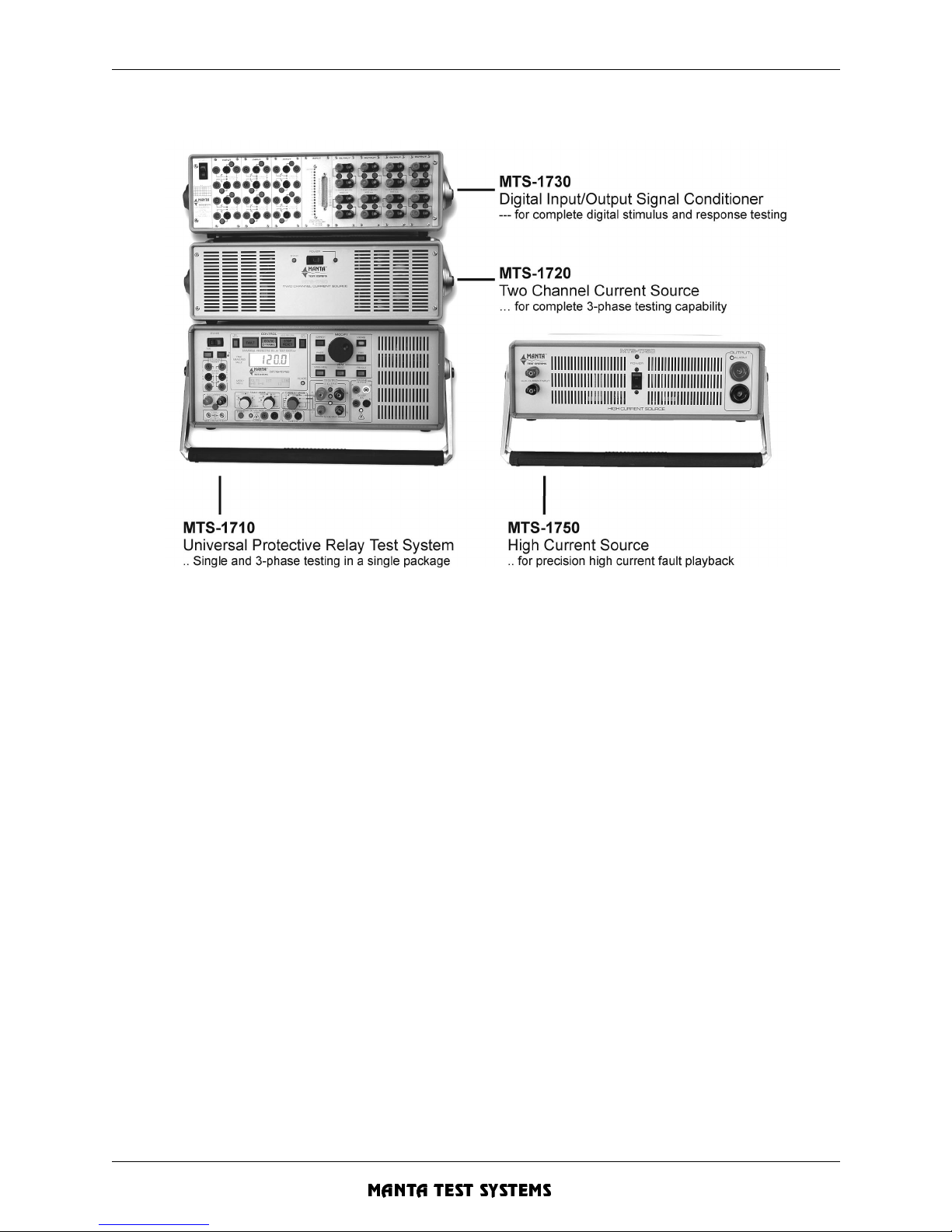
INTRODUCTION - Section 1
1-2 M T S-1700 SERIES OPERATION AND REFERENCE MANUAL
MANTA TEST SYSTEMS
CU A002 15A
FIGURE 1.1 MTS-1700 SYSTEM
The MTS-1710 alone can test the majority of single and three-phase devices (except those requiring full
three-phase current), as well as differential relays. Add the MTS-1720, two channel current source for full
three-phase current capability. Add the MTS-1730 for full digital testing capability, especially under automatic computer control. Add the MTS-1750, high current source, for testing where precision high curre nts
are r equired.
All four of the instruments can be computer controlled in each of the seven possible configurations (MTS1710 only; MTS-1710 + MTS-1720; MTS-1710 + MTS-1750; MTS-1710 + MTS-1720 + (3)MTS-1750s;
MTS-1710 + MTS-1730; MTS-1710 + MTS-1720 + MTS-173 0; or MTS-1710 + MTS-1720 + MTS-1730
+ (3) MTS-1750s) using the MTS-1780 Protective Relay Test So ftware.
Controlled sourcing of 3-phase voltage, and a single phase current, is provided internally. Complete
programmability of a mp li tu de , p h ase a nd fr eq ue nc y of th e v ol ta ge an d cur r ent o ut pu ts is pr o vi de d.
Measurement of all output parameters, as well as start/stop timing, are availa ble via front panel control.
The MTS-1700 system is particularly designed for simulation of faults in three phase systems. Advanced
fault simulation capabilities, such as frequency, voltage, current and phase ramping, are standard. Full
control of all functions via the RS-232C computer interface paves the way for automated testing of many
types of protection rela ys.
The fault playback capabilities of this unique field instrument will link field testing back to protective
system engineering. It allows engineers to subject relays to predicted characteristic faults (based upon
computer simulation models), or abnormal faults, and analyze their performance before implementation.
Page 33
INTRODUCTION - Section 1
MTS-1700 SERIES OPERATION AND REFERENCE MANUAL 1-3
CU A002 15A
MANTA TEST SYSTEMS
Furthermore, when actual faults do occu r, digital fault records can be rec onstr ucted using the MTS-1710 to
re-subject the relay (in the field) to the fault events. Analysis of these tests can lead to modifying relay
settings or other prote ctive circuitry to prevent future problems.
1.3 APPLICATIONS
1.3.1 Standard Applications
• Static, dynami c te stin g and calibration of virtually all protective relays, including:
• On panel testing of relay systems, both steady-state and dynamic operation.
• 3Φ transducer testing/calibration.
• Voltage, curr ent, phase, frequency, Wa tt, VAR transducers.
• Power swing (out-of-step) simulation/testing.
1.3.2 Fault Playback Applications
• Playback of digital fault records, or relay eve nt reports, into relays an d relay systems for fault and
misoperation analy sis
• Fault simulation, harmonic sourcing, and transient simulation for relay and relay system testing
- Inrush current simulation/testing (including DC offset)
- Ground resistance testin g
- Playback of multiple and evolved faults.
• Digital fault r ecorder testing.
• Playback of EMTP output waveforms to relays and relay systems for simulation of hypothetical or
predicted system faults.
• Simulation o f non-zero source im pedance fo r testing i mpedan ce relays . (Perf ormed with th e assi stance
of EMTP simulation output).
• Generation of user-defined power waveforms for relay sensitivity testing.
• Testing of pilot wire relaying systems.
• Power system modelling.
• Relay qualification and acceptance testing.
Over/undercurrent
Impedance/Distance
Under/overfrequency
Directional overcur rent
Synchrocheck
Transformer differential
Volts-per-Hertz
Out-of-step
Reclosing/synchronizing
Multi-function dist ance
Breaker failure
Over/undervoltage
Mho
Frequency rate-of -change
Line Differential
Motor protection
Reve r se power
Time overcur rent
Loss of excitation
DC time delay/auxiliary
Negative sequence
Page 34

INTRODUCTION - Section 1
1-4 M T S-1700 SERIES OPERATION AND REFERENCE MANUAL
MANTA TEST SYSTEMS
CU A002 15A
1.4 TERMINOLOGY
The following section cla rifies terminology defining various approaches to relay testing.
The MTS-1700 Series Universal Protective Relay Test System is very versatile, and may be used in all
these types of relay test ing.
1.4.1 Static Relay Testing
Static relay testing refers to testing of relays using very slowly varying inputs to accurately locate pickup
points and to perform repeatable measurements.
1.4.2 Dynamic Relay Te sting
This form of testing refers to testing of relays using instantaneous steps/ramping of voltage and current
inputs.
To closely simulate conditions during in-service operation, the voltages and currents are typically stepped
from a nominal level to a pre-determined fault level. The MTS-1710 has the unique ability to perform
dynamic testing under manual con trol.
1.4.3 Fault Playback
Fault playback refers to the regeneration of digitized voltage and current waveforms at high power levels.
The waveform data may originate from any of the following sources:
a) Fault records from digital fault recorders
b) Digital simulatio n output e. g. from Electromagnetic Transient Program (EMTP)
c) Event reports from microprocessor-based relays
d) User-defined waveforms
e) Fault record lib ra ri es
Playback of these waveforms allow actual and hypothetical fault events to be re-created. Analysis of
protective relay system performance can also be carried out as a result of these events. Real-time
simulation and analysis of system response to transients and other abnormal conditions is further
permitted.
For a more detailed discussion of this application, see the paper “Protective Relay Digital Fault Recording
and Analysis” by Elmo Price, Conference of Protective Relay Engineers, Texas A&M University, April,
1998.
1.4.4 On-Panel Testing
This refers to testing of relays and relay systems while they’re installed on panels and equipment racks.
This involves injecting voltages and currents directly to the panel to test complete system response, and to
verify correct inpu t/output wiring and phasing.
Page 35
INTRODUCTION - Section 1
MTS-1700 SERIES OPERATION AND REFERENCE MANUAL 1-5
CU A002 15A
MANTA TEST SYSTEMS
1.5 TECHNICAL SUPPORT
The design of this instrument reflects decades of experience in the electric power industry. Manta Test
Systems recognizes, however, that there will be testing situations encountered which were not considered
during product design, and we want it to be the product which best serves your specific needs.
Manta Test Systems subsequently encourages any user questions, problems or suggestions to be forwarded
to us, either via the representative through which the product was purchased, or directly to us via the fax
numbers provided on the front cover.
Users who make suggestions for worthwhile improvements may be eligible for free upgrading of their
instrument.
All technical inquiries and questions regarding service, repair and calibration of products formerly sold
under the brand name “Powertec
” should be directed to:
MANTA TEST SYSTEMS INCORPORATED
Toll free customer support: 1-800-233-8031 (USA & Canada)
Fax: 1-905-828-6850
Telephone: 1-905-828-6469
e-mail: [email protected]
Technical support phone numbers are also shown in the front panel menu of the MTS-1710 under the
OTHER SERV TECHNICAL-SUPPORT selection.
1.6 SAFETY CONSIDERATIONS
This instrument can generate high le vels of current and voltage. Incorrect usage may cause per sonal injury
or damage to the instrument.
The user must be qualifie d to work safely in the intended application environment of this instrumen t. Nonadherence to the following minimum requirements constitutes misuse of the MTS-1710, and the
manufacturer accepts no liability for damages arising from such misuse:
1) The instrument case must always be effectively grounded. The rear panel grounding stud must be
connected via m inimum 12 gauge wire to a known secure ground to suppl ement the power supply cord
ground.
2) All leads and connectors should be in good condition and rated for the appropriate voltage and current
carrying re quirements. Current outputs must be securely connected with minimum 12 gauge leads with
C-hook terminals.
3) The outputs must not be connected to live outputs or live equipment.
4) All outputs must be turned off before making changes in connections.
Page 36

INTRODUCTION - Section 1
1-6 M T S-1700 SERIES OPERATION AND REFERENCE MANUAL
MANTA TEST SYSTEMS
CU A002 15A
5) Never exceed the following maximum ratings:
(a) 300Vrms to ground on any input (power or control)
(b) 300VDC differen tial to external trigger inputs
6) All rear panel fuses must contain properly rated fuses.
1.7 LIMITED PRODUCT WARRANTIES
1.7.1 Hardware
Manta Test Systems warrants that its hardware products, and the hardware components of its products,
shall be free from defects in materials and workmanship under normal use and service for a period of one
year from the date such products are shipped from Manta Test Syste ms.
Provided that Manta Test Systems receives notice of any defects in materials or workmanship of its
hardware products, or hardware components of its products, within such one-year period, Manta Test
Systems shall, at its optio n, either repair or repla ce the defect ive hardware pro duct or hardware compon ent,
if proven to be defective.
1.7.2 Software & Firmware
Manta Te st Systems warrants that its software products, and the software and firmware components of its
products, shall not fail to execute their programming instructions under normal use and service, due to
defects in materials and workmanship, if properly installed on intended hardware, for a period of one year
from the date such products are shipped from Manta Test Systems .
Provided Manta Test Systems receives notice of such defects within the warranty period, it shall, at its
option, either repair or replace the software or firmware media, if proven to be defective.
1.7.3 Separate Extended Warranty for Hardware Products
Aside from the standard warra nty set forth above, Manta Test Systems offers a separate extended warranty
plan for all hardware products (excluding cables, batteries and accessories) which may be purchased, and
extends the standard warra nty by one additional year.
The extended warranty is issued under the same terms, conditions and exclusions as the standard warranty
set forth herein. Pricing is based upon the cost of the product, and the average cost of servicing and
calibration. Refer to the Manta Test Systems price list available from your local representative, or Manta
T est Systems, for extended warranty pricing for specific products.
The extended warranty must be purchased and paid for within three months from the date the product is
shipped from Manta Test Systems.
Page 37
INTRODUCTION - Section 1
MTS-1700 SERIES OPERATION AND REFERENCE MANUAL 1-7
CU A002 15A
MANTA TEST SYSTEMS
EXCLUSION OF OTHER WARRANTIES AND LIMITATION OF REMEDIES
1.7.4 Exclusion of other Warranties
THE FOREGOING WARRANTIES ARE EXCLUSIVE, AND ARE IN LIEU OF ANY AND ALL OTHER
WARRANTIES (WHETHER WRITTEN, ORAL OR IMPLIED) INCLUDING, BUT NOT LIMITED TO,
WARRANTY OF MERCHANTABILITY IN OTHER RESPECTS THAN AS SET FORTH ABOVE, AND
WARRANTY OF FITNESS FOR A PARTICULAR PURPOSE.
Limitation of Liability and Remedies
IT IS UNDERSTOOD AND AGREED THAT MANTA TEST SYSTEMS’ LIABILITY AND
PURCHASER’S SOLE REMEDY, WHETHER IN CONTRACT, UNDER ANY WARRANTY, IN TORT
(INCLUDING NEGLIGENCE), STRICT LIABILITY OR OTHERWISE, SHALL NOT EXCEED THE
COST OF REPAIR OR REPLACEMENT OF MANTA TEST SYSTEMS’ P RODUCTS, AS SET FORTH
ABOVE, AND, UNDER NO CIRCUMSTANCES, SHALL MANTA TEST SYSTEMS BE LIABLE FOR
ANY SPECIAL, INCIDENTAL, OR CONSEQUENTIAL DAMAGES, INCLUDING, BUT NOT
LIMITED TO, PERSONAL INJURY, PROPERTY DAMAGE, DAMAGE TO OR LOSS OF
EQUIPMENT, LOST PROFITS OR REVENUE, COSTS OF RENTING REPLACEMENTS, AND
OTHER ADDITIONAL EXPENSES.
FURTHERMORE, IT IS UNDERSTOOD AND AGREED THAT MANTA TEST SYSTEMS SHALL
NOT BE LIABLE FOR ANY DAMAGES, LOSSES OR EXPENSES AS A RESULT OF THE
PURCHASER’S OR ANYONE ELSE’S:
I. NEGLIGENCE (WHETHER DEEMED ACTIVE OR PASSIVE),
II. MISUSE, ABUSE, OR MODIFICATION OF MANTA TEST SYSTEMS PRODUCTS,
III. USE OR OPERATION OF PRODUCTS NOT IN CONFORMITY WITH THE SPECIFICATIONS
AND INSTRUCTIONS FURNISHED BY MANTA TEST SYSTEMS FOR ITS PRODUCTS,
IV. REPAIR OR MAINTENANCE OF MANTA TEST SYSTEMS’ PRODUCTS BY PERSONS OR
ENTITIES NOT AUTHORIZED BY MANTA TEST SYSTEMS, OR
V. DAMAGE TO, OR DESTRUCTION OF, PRODUCTS, DURING DELIVERY TO MANTA TES T
SYSTEMS FOR ANY REASON.
Limitation of Warranty Regarding Software
Manta Test Systems does not warrant that the operation of the software, firmware or hardware shall be
uninterru pte d or erro r fre e.
1.7.5 Extension of Warrant y
At the discre tion of Manta Test Systems, the warr anty may be extended for a product whic h has been retu rned
for service shortly after its warranty period has expired.
Page 38

INTRODUCTION - Section 1
1-8 M T S-1700 SERIES OPERATION AND REFERENCE MANUAL
MANTA TEST SYSTEMS
CU A002 15A
Page 39
SPECIFICATIONS - Section 2
MTS-1700 SERIES OPERATION AND REFERENCE MANUAL 2-1
CU A002 15A
MANTA TEST SYSTEMS
SPECIFICA TIONS
NOTE: All specifications are subject to change. All AC quantities are RMS values, except as
otherwise noted.
Power outputs are specified for nominal 120VAC/60Hz or 240VAC/50Hz power input,
and 25°C ambient operating temperature. Derating applies for lower input power
voltages and higher ambient temperatures.
For all current outputs, maximum obtainable current will vary inversely with load
impedance. For extended operation at high power output levels, ensure adequate cooling
(i.e. tilt stand raised to aid air flow to bottom inlets, and adequate clearance for exhaust
outlets).
2.1 INPUTS
Single phase 105-130VAC @ 15A max (or 210-250VAC @10A max), factory set
External Star t/Stop trigger inputs
for externally trigge ring fault initiation/term ination
NC or NO wet/dry contact sensing
DC/AC voltage sensing (10V thresho ld level, 52k ohms input impedance minimum)
2.2 OUTPUTS
3-phase wye voltage
0-150 V rms phase-neutral, direct coupled
85 VA (1.13A) per phase maximum @ 75V Φ-N output, P.F.=1.0
60 VA (0.8A) per phase maximum @ 75V Φ-N output, P.F.=0.5
52.5 VA (0.7A) per phase maximum @ 75V Φ-N output, P.F.=0
120 VA per phase maximum @ 150V Φ-N output, P.F.=1
Single phase current
Switched to 3 phase output terminals, direct coupled
0-30A rms, 400VA maximum, 44V rms maximum
For simultaneous 3-phase current, MTS-1720 required
Typical performance:
0 - 25A into 0.24Ω (150VA maximum)
0 - 20A into 0.75Ω (300VA maximum)
0 - 15A into 1.8Ω (400VA maximum)
0 - 10A into 3.5Ω (350VA maximum)
0 - 5A into 8Ω (200VA maximum)
Additional current modes:
• 0-6 A DC mode
• Mixed harmon ic current mode for harmonic restraint testing
• High current 0-90A @3V AC mode for instantaneous tests (7.5VAC maximum compliance
voltage)
• Dual AC current mode for slope tests (I1: 60A maximum, 50A @3V, I2: see above for single
phase current)
Page 40
SPECIFICATIONS - Section 2
2-2 MTS-1700 SERIES OPERATION AND REFERENCE MANUAL
MANTA TEST SYSTEMS
CU A002 15A
• Parallel current mode allows paralleling of current outputs of MTS-1710 and MTS-1720 for
up to 90A max, 1000 VA max, 44 Vrms max.
• I2-Harmonic maximum current of 17A
Output frequency
• power line (frequency and phase locked)
• 1st through 10th harmonic of power line
• variable 40.000 - 80.000 Hz (0.001 Hz resolution, 0.01% accuracy)
80.00 - 800.00 Hz (0.01 Hz resolution, 0.02% accuracy)
• 25Hz frequency mode
Four output level settings:
• off, prefault, fault, postfault
Phase control:
• Phase between current and any voltage is adjustable from 0 through 360°
• Adjus tment resolution: 0.25°
Auxilary output contacts:
• Two auxili ary output contacts
• Confi gurable as NO, NC, 52A, 52B (Aux. contacts 1 & 2), Permissive or Unblocking with
programmable delay (Aux. contact 1 only)
2.3 METERING
All outputs are directly metered. This allows direct readout of Φ-Φ and Φ-N voltages, currents and
interphase angles.
Time, frequency, phase, current and voltage are measured simultaneously. In addition, the phase is always
measured between the monitor voltage and the current, allowing all standard phase angle relations to be
directly displa yed.
• AC Voltage measurements: A-N, B-N, C-N, A-B, B-C, C-A
True RMS responding, autoranging
Voltage scales (approx):0-82V, 82-327V
Accuracy: ±0.5% of reading ± 0.2% of scale
• AC Current measurements: Measures actual output current
True RMS responding, autoranging
Current scales (approx): 0- 8.2A, 8.2-32.7A
High current scales (approx): 0-24.5A, 24.5-98.3A
Accuracy: ±0.5% of reading ± 0.2% of scale
• DC Current measurement: Measures actual output current:0 - 10.00A scale
Accuracy: ±1% of reading ±0.2% of scale
• Phase measurement: Accuracy: ±0.5° for input levels >5% of range
0 -359.9° or 0 - ±180° display modes
Selectabl e V-leads-I or I-leads-V me as u rem en t reference
Page 41
SPECIFICATIONS - Section 2
MTS-1700 SERIES OPERATION AND REFERENCE MANUAL 2-3
CU A002 15A
MANTA TEST SYSTEMS
• Time measurement: Measures fault interva l from either internal or external start trigge r
0 -99999 sec or 0 - 99999 cycles, autoranging scale
best resolution: 0.1 ms/ 0.1 cycles
accuracy: 0-9.9999sec scale: ±0.5ms ±1 least significant digit
all other scales: ±0.005% ±1 least significant digit
two-wire pulse timing mode
• Frequency measurement: power line frequency measurement (accuracy & resolution: ±0.01Hz)
variable frequency value displayed to 0.001Hz resolution
2.4 COMPUTED MEASUREMENTS
• Impedance (V÷I, V÷2I , V÷1.732I, V÷((1+k)I) ) with programmable k-factor
• Resistance (Re(V÷I), Re(V÷2I) , Re(V÷1.732I), Re(V÷((1+k)I)) ) with programmable k-factor
• Reactance (Im(V ÷I) , Im( V÷2 I) , Im( V÷1.7 32 I), Im(V ÷((1 + k)I)) with program m able k-f acto r
• Single phase power (Watts, Vars, VA, Power Factor)
• I1÷I2, I2÷I1, (I1-I2)÷((I 1+I2 ) ÷2), I2÷(( 2I 1+I 2) ÷2), wi th p rog ram ma b le CT tap va lue s for I1 , I2
• %harmonic current
• V÷Hz
• Breaker advance time, breaker closing angle
2.5 STATIC/DYNAMIC TESTING CAPABILITIES
• Phase to neutral faults
• Phase to phase faults
• Three phase faults
• Two phase to neutral faults
• Phase, frequency, voltage and current stepping
• Phase, frequency, voltage and current ramping with adjustable rate of change
• Presettable fault durations, 0 -99.9999 sec
• Programmable auto-reclose time delay and reclose-into-fault events
• Programmable breaker time
• Three-pole and single-pole tripping
• Programmable PT location simulation
2.6 FAULT PLAYBACK
• Ability to accept fault data from fault rec orders, EMTP simulation outputs, or user-de fined waveforms
• Sample rate: programmable 2-30 kHz
• Record length: 8 bit: 8000 samples per each of four channels (six channels available when
MTS-1720 is also used)
14 bit
: 60k samples per each of four channels (six channels available when
MTS-1720 is also used)
• Resolution: 8 bit: 8 bit dynamic + 12 bit scaling
14 bit: 14 bit dynamic + 16 bit scaling
• Peak output levels: ±230.5V for voltage chan nels
±42.4A for current channels
Page 42
SPECIFICATIONS - Section 2
2-4 MTS-1700 SERIES OPERATION AND REFERENCE MANUAL
MANTA TEST SYSTEMS
CU A002 15A
2.7 RS-232C INTERFACE
• Two ports, optically isolated
• All instrument functions are RS-232C controllable
• Standard baud rates from 300 to 38400 baud
• XON/XOFF handshaking protocol (hardware handshaking must be enabled when 38400 baud is used)
• Easy-to-use terminal mode
2.8 APPLICATION SOFTWARE
Provided with the MTS-1710:
• MTS-2100, MTS-2150, Powerscope demonstration program
• Syncscope demonstration program
Available separately:
• MTS-2800 “MPower
TM
” for Windows: Protective Relay Test Environment for the Manta Test
Systems MTS-1700 Series
• MWave Fault Wavef orm Playback Software
• MTS-1900 Utility Suite - utility programs enhance the use of various features of the MTS-1700 series.
2.9 OPTIONS
• Option -03: Programmable digital I/O and trigger channe ls
• Option -04: Low level input to power amplifiers for advanced fault playback & external
phase/frequency sync input
• Option -07: Auxiliary DC voltage output. 24-300VDC @ 100VA maximum output to
supply auxiliary power to device(s) under test.
• Option -10: Hardshell shipping case with rollers
• Option -11: Cordura carry case
• Option -12: French display
• Option -14: 19” Rackmount enclosure
• Option -15: 240V, 50/60Hz line input
• Option -16: Default 110V/50Hz output
• Option -18: Foot Switch - for enabling the fault state when doing steady state te sting
• Option -19: Additional Operation and Reference Manual
• Option -2 0 : 1 Year ex t en d e d wa rr a nt y
Additional year for a total of two years.
• CABLE C1 MTS-1710 to SEL-121 communication cable
• CABLE C2 MTS-1710 to SEL-221, SEL-251, and SEL-321 relay communication cable
• CABLE C1 MTS-1710 to GEC Optimho relay communication cable
• MTS-1720 T wo Channel Current Source (Integrates to build a full 3Φ-voltage, 3Φ-
current system)
• MTS-1730 Digital Input/Output Signal Conditioner
• MTS-1750 High Current Source
Page 43
SPECIFICATIONS - Section 2
MTS-1700 SERIES OPERATION AND REFERENCE MANUAL 2-5
CU A002 15A
MANTA TEST SYSTEMS
2.10 ADDITIONAL STANDARD FEATURES
•
Fault incidence angle cont rol
• Synchronizing mode for testing synchronizing devices
• Internal clock /calendar
• Audible feedback tone
• Programmable auxiliary contact outputs for slaving other devices
• Circuit breaker-advance time measurement
• High speed measurement modes
• Breaker signal (52A/52B) simulation
• Permissive/unblock signal simulation (with programmable delay)
• Multi-system synchr onization
• User settable default output voltages and frequency
2.11 PHYSICAL CHARACTERISTICS
• 19”W x 7.5”H x 18”D (48.3cm W x 19.1cm H x 45.7cm D)
• Weight: 60.0 lbs (27.2 kg) without front/rear protective covers 63.4 lbs (28.7 kg) with front/rear
protective covers
• Built-in carry handle/tilt stand
Page 44

SPECIFICATIONS - Section 2
2-6 MTS-1700 SERIES OPERATION AND REFERENCE MANUAL
MANTA TEST SYSTEMS
CU A002 15A
Page 45
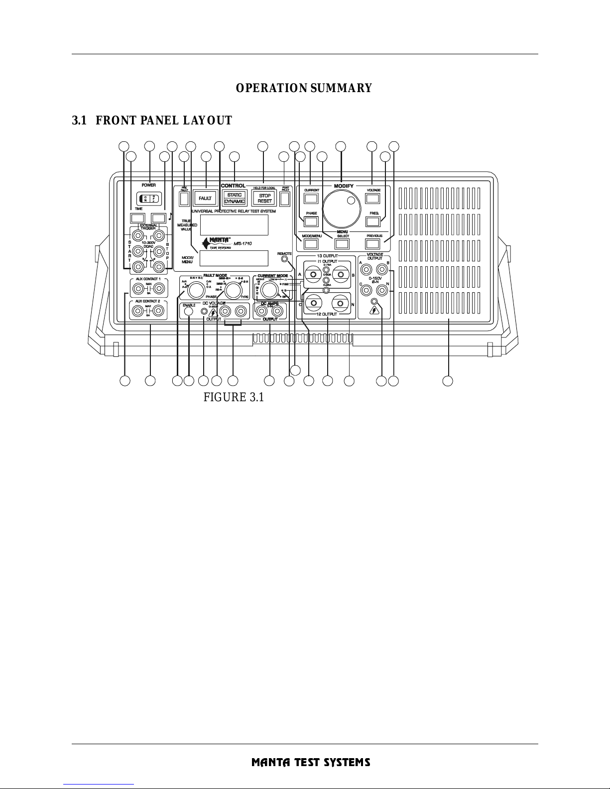
OPERATION SUMMARY - Section 3
MTS-1700 SERIES OPERATION AND REFERENCE MANUAL 3-1
CU A002 15A
MANTA TEST SYSTEMS
OPERA TION SUMMARY
3.1 FRONT PANEL LAYOUT
FIGURE 3.1 FRONT PANEL LAYOUT
NOTE: Text in square [] brackets is used to denote various controls throughout this manual.
1. [EXTERNAL START] TRIGGER INPUTS
These three input terminals allow external contact or voltage signals to initiate a test. The lower
and centre terminals detect impedance change-of-state, such as contact closure or low-impedance
voltage source appearance. The upper and centre terminals detect voltage change-of-state.
2. [TIME] PUSH B U T TON
This button selects the ti mer display. Pressing [TIME] more than once toggles between the time in
cycles and time in seconds displ ay mode.
3. [POWER ] SWITCH
This switch turns on the MTS-1710.
4. [TONE] PUSHBUTTON
This pushbutton toggles the tone indicator on/off and is intended to facilitate detection of external
relay operation.The light indicates when either a closed contact or active voltage is sensed on the
[EXTERNAL STOP] trigger input s.
1
2
3
456 8
7 9
10
11
12
131415
18
17
16
20
19
21
22 23 24 25 26 27 28
2930313332343
5 36
Page 46

OPERATION SUMMARY - Section 3
3-2 MTS-1700 SERIES OPERATION AND REFERENCE MANUAL
MANTA TEST SYSTEMS
CU A002 15A
5. [EXTERNAL STOP] TRIGGER INPUTS
These three i nput terminal s allow extern al contac t or voltage signa ls to stop a test .The lower an d
centre terminals detect impedance change-of-state, such as contact closure or low-impedance
voltage source appearance. The upper and centre terminals detect voltage change-of-state.
6. [PREFAULT] PUSHBUTTON
This pushbutton toggles PREFAULT voltage and current on/off. When lit, this indicates that
PREFAULT voltages and currents may be non-zero.
7. [MODE/MENU DISPLAY]
This display is used to annunciate active modes and selections. It’s also used for displaying the
built-in menu for advanced use rs, and to annunciate warnings.
8. [FAULT] PUSHBUTTON
When this button is lit, it indicates that the MTS-1710 is in the fault state. When depressed, this
pushbutton causes the MTS-1710 to enter the FAULT state, and applies the fault voltages and
currents to the outputs.
9. [VALUE DISPLAY]
This is the large LCD display for displaying values and settings.
10. [STATIC/DYNAMIC] PUSHBUTTON
This pushbutton selects between static and dynamic operation modes.
11. [STOP/RESET] PUSHBUTTON
This pushbutton stops a dynamic test in progress, or resets the MTS-1710 in the POSTFAULT
state. After pressing this button, the MTS-1710 returns to the PREFAULT state. When this button
is illuminated, the MTS-1710 is in the POSTF AULT state, and all measurements have been frozen
at their values when the stop tri gger occurred.
12. [POSTFAULT] PUSHBUTTON
This pushbutton toggles POSTFAULT voltage and current on/off. When lit, this indicates that
POSTFAULT voltages and currents may be non-zero.
13. [MODE/MENU] PUSHBUTTON
This pushbutton toggles between the mode and menu displays. When lit, this indicates that the
menu is active and that the non-menu controls will be inoperable.
Page 47
OPERATION SUMMARY - Section 3
MTS-1700 SERIES OPERATION AND REFERENCE MANUAL 3-3
CU A002 15A
MANTA TEST SYSTEMS
14. [PHASE] PUSHBUTTON
This button selects the phase display, and enables phase angle to be adjusted. Pressing this button
more than once toggles between the 0-35 9.9° and 0-± 180.0° display scales.
Note: On older MTS-1710 systems, this button may be labelled “PHASE V-I”.
15. [CURRENT] PUSHBUTTON
This button selects the current display, and enables current to be adjusted. Pressing this button
more than once may toggle between different current outputs, depending upon the selected current
mode.
16. [SELECT] PUSHBUTTON
This button is used to select a particular menu item when the menu is active.
17. [MODIFY] KNOB
All settings adjustments are made with this spin knob. The knob sensitivity depends upon the
speed at which it’s turn ed.
Turning the knob slowly makes fine adjustments. Turning the knob at a moderate speed--and very
fast--makes medium and coarse adjustments respectively.
18. [VOLTAGE] PUSHBUTTON
This button selects the voltage display, and enables the voltage(s) selected by the [FAULT
PHASE] selector to be adjusted.
19. [FREQ] PUSHBUTTON
This button selects the frequency display, and enables the frequency to be adjusted. Pressing
[FREQ] more than once toggles between the line reference frequency mode and the variable
frequency mode.
20. [PREVIOUS] PUSHBUTTON
When the menu is active, this button is used to return to a previous level in the menu. When the
menu isn’t active, it returns to the last menu screen accessed.
21. [AUX CONTACT 1] OUTPUT TERMINALS
These auxiliary contact terminals are closed whenever the MTS-1710 is in the FAULT state. They
may be used to slave an external device, such as a chart recorder, or simulate a breaker. Auxuliary
contact 1 can be used to test premissive and unblocked transfer schemes.
Page 48
OPERATION SUMMARY - Section 3
3-4 MTS-1700 SERIES OPERATION AND REFERENCE MANUAL
MANTA TEST SYSTEMS
CU A002 15A
22. [AUX CONTACT 2] OUTPUT TERMINALS
These auxiliary contact terminals are closed whenever the MTS-1710 is in the FAULT state. They
may be used to slave an external device, such as a chart recorder, or to switch an additional current
or voltage.
Both contacts 1 and 2 are rated at 5A/120VAC and may be programmed for other functions (see
Section 5.15).
23. [FAULT PHASE] SELECTOR
This switch selects the phase being faulted. As well, this phase of voltage is monitored and used
for phase measu rem en t.
24. [DC VOLTAGE ENABLE] PUSHBUTTON
This pushbutton is used to enable/disable the DC voltage output.
25. [DC VOLTAGE LIVE] LED
This LED, when on, indicates that the DC voltage output is live. Green indicates 22-70V; yellow
indicates 70-130V; and red indicates 130-300V.
26. [FAULT TYPE] SELECTOR
This knob selects the type of fault to be simulated.
27. [DC VOLTS] OUTPUT TERMINALS
DC voltage output terminals fo r units with the DC Voltage output option.
28. [DC AMPS] OUTPUT TERMINALS
These terminals provide DC current output in the I4 current mode.
29. [CURRENT MODE] SELECTOR
This knob selects the activ e curre nt mode.
30. [REMOTE] LED INDICATOR
When lit, this LED indicates that the MTS-1710 is under remote control.
31. [I1 OUTPUT] TERMINALS
These output terminals provide output current in the I1-LOW and I1-HIGH current modes.
Page 49
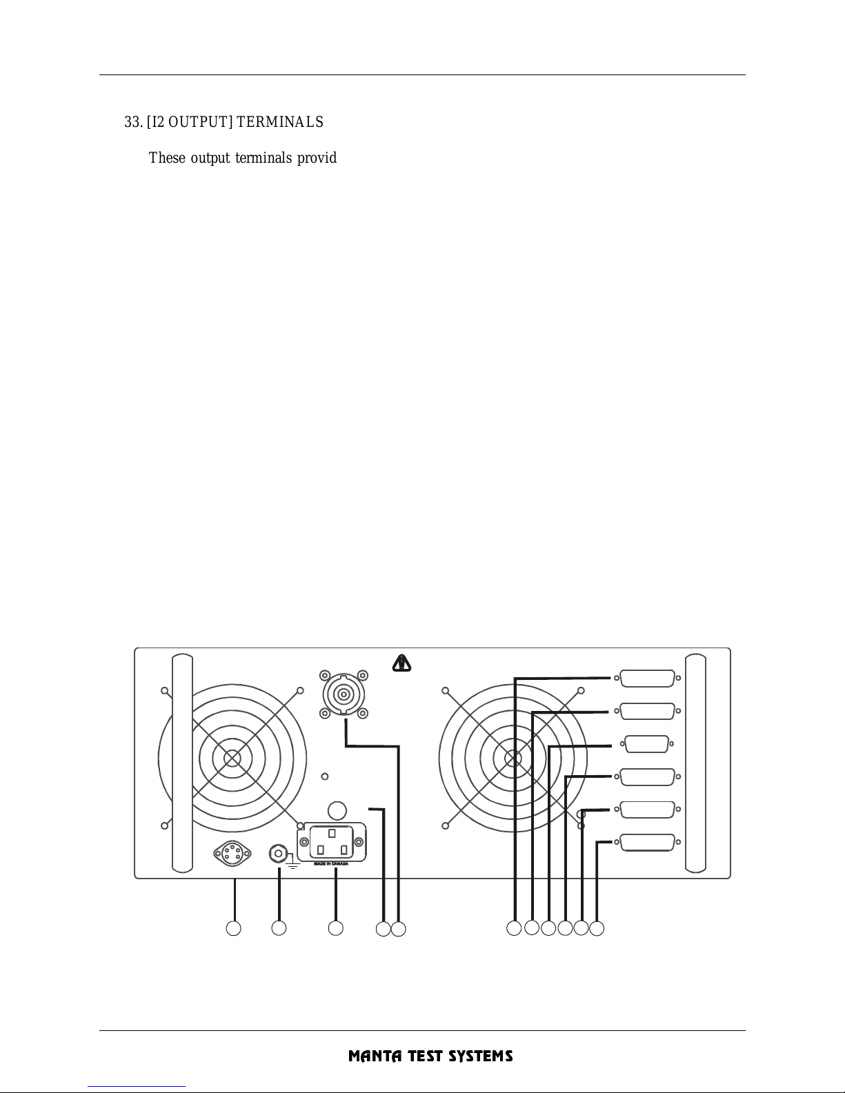
OPERATION SUMMARY - Section 3
MTS-1700 SERIES OPERATION AND REFERENCE MANUAL 3-5
CU A002 15A
MANTA TEST SYSTEMS
33. [I2 OUTPUT] TERMINALS
These output terminals provide the I2 output current in the I2-HARMONIC and I1&I2 current
modes.
34. [I3 OUTPUT] TERMINALS
These output ter minals provide the I3 output c urrent in the I3 and I3-WYE current modes. They’re
actually the same terminals as the I1 and I2 output terminals. The terminals are simply interpreted
as A, B, C and N outputs (marked in red). The internal single phase current is switched to the
appropriate A, B, C and N terminals based upon the selected FAULT MODE.
35. [AC VOLTAGE OUTPUT LIVE] LED
This LED indicates when AC voltage outputs are potentially live.
[VOLTAGE MONITOR] OUTPUT TERMINALS (Not illustrated, older MTS-1710 syst ems only)
These term in al s allo w an e x te rnal v oltm et er t o mo n it or the acti v e vo ltag e (s elect ed b y th e FAULT
MODE selectors).
36. [VOLTAGE OUTPUT] TERMINALS
These are the 3-
Φ wye-connected output vol tage terminals.
37. COOLING INTAKE
3.2 REAR PANEL LAYOUT
FIGURE 3.2 REAR PANEL LAYOUT
AUX OUTPUT S
AUX INPU TS
MTS-1750
COM 3 SLAVE CURRENT
COM 2 RS-232C
COM 1 RS-232C
MAINS
F15A
SLAVE CURRENT IN
POWER OFF
BEFORE
CONNECTING/
DISCONNECTING.
ROTATE TO LOCK
BEFORE USE
SIGNAL INPUT
12
34
5
687
10119
Page 50
OPERATION SUMMARY - Section 3
3-6 MTS-1700 SERIES OPERATION AND REFERENCE MANUAL
MANTA TEST SYSTEMS
CU A002 15A
1. [SLAVE CURRENT IN] CONNECTOR
Current input from MTS-1720. Two channel current source for B & C phase currents.
2. MAINS INPUT FUSE
This is the main AC input fuse. For 120V systems, replace only with a fast blow, 15A/250VAC
fuse. For 240V systems, replace only with a fast blow, 8A/250VAC fuse.
AMPLIFIER O U TPU T FUSES (not illus tra ted )
These are the voltage A, B, C amplifier output fuses. The VA and VB fuses are fast blow 4A fuses.
The VC fuse is a 5A, fast blow fuse.These fuses are only present on earlier model MTS-1710’s
with 125V output voltage amplifiers (shipped before Aug 10, 1994).
3. AC INPUT RECEPTACLE
This is the main AC input receptacle.
4. SAFETY FRAME GROUND TERMINAL
5. EXTERNAL AMP SIGNAL INPUT
Optional inputs for advanced fault playback and external frequency reference.
6. [AUX OUTPUTS] PORT
Digital outputs port for the Programmable I/O channels option.
7. [AUX INPUTS] PORT
Digital inputs port for the Programmable I/O channels option.
8. [MTS-1750] PORT
Connection to MTS-1750 High Current Sour ce via DB 15.
9. [COM 3 SLAVE CU RR E N T] PORT
Communications port connector to MTS-1720. Two channel current source.
10. [COM2 RS-232C] PORT
Spare communications port which may be used to contr ol auxiliary devices.
11. [COM1 RS-232C] PORT
Main MTS-1710 RS-232C serial interfa ce port.
Page 51
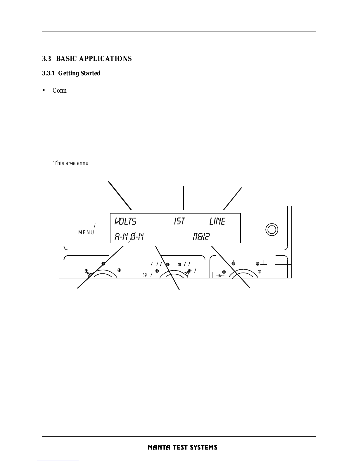
OPERATION SUMMARY - Section 3
MTS-1700 SERIES OPERATION AND REFERENCE MANUAL 3-7
CU A002 15A
MANTA TEST SYSTEMS
3.3 BASIC APPLICATIONS
3.3.1 Getting Start ed
• Connect main power, and safety ground.
• Turn on the MTS-1710 [POWER] switch.
Note the status indicated in the (lower) [MODE/MENU DISPLAY]. This indicates all the primary modes
which have been selected.
FIGURE 3.3 MODE/MENU DISPLAY
FAULT MODE
C
URRENT MODE
VOLTS LINE
A-N O-N
I1&I2
C-N
C-A
A-N
A-B
B-N
B-C
O-N
O-O30
(0-0)
REMOTE
I1
(0-N)
I4
H
IGH
MODE/
MENU
30
This area annunciates
the units associated
with the (upper) value
display.
This area annunciates
the timer start mode
IST = Internal timer start
XST = External tim er start
This area indicates the
selected F AULT MODE PHA SE.
This area indicates the
s
electe d CURRENT M OD E.
This identifies which
current outputs are
active and adjustable.
This area indicates the
selected FAULT MODE TYPE.
The FAULT MODE TYPE
determines what type of
fault is being simulated.
The FAULT MODE PHASE
determines which phase
is being faulted.
It is also the voltage
which is monitore d, and
the voltage which is
used for the phase
measurement.
In I3 current mode, the
FAULT MODE PHASE
is the current path from
the I3 current output.
T
his area indicates the
F
requency mode. "LINE" signifies
that the output is phase
and frequency locked to
the input line power.
In variable frequency mode,
the actual output frequency
is displayed here.
L
OW
I1&12
Page 52
OPERATION SUMMARY - Section 3
3-8 MTS-1700 SERIES OPERATION AND REFERENCE MANUAL
MANTA TEST SYSTEMS
CU A002 15A
3.3.2 Safety & other precautions
3.3.2.1 SAFETY
• The AC yellow LED under the AC voltage output terminals indicates when AC voltage is potentially
live (not present on older models) .
• Whenever any of the red [PREFAULT], [FAULT] or [POSTFAULT] lights are lit, there are potentially
live AC outputs.
• The DC voltage output may be live at all times. This is indicated by the LED beside the DC voltage
output terminals (not pr esent on older units).
3.3.2.2 ISOLATION
• All outputs are isolated from the AC input supply and case/earth ground to a maximum of 300 VAC/
DC.
• The start & stop trigger inputs are isola ted from each other, from the AC input supply, from the AC/DC
outputs, and from the case/earth ground.
• The AC current and voltage outputs share a common return/ground.
3.3.2.3 PROTECTION
• The AC voltage output is protected from short circuits, overloads and overtemperature.
• The AC current output is protecte d from open circuits, overloads and overtemperature .
3.3.2.4 PRECAUTIONS
• DON'T CHANGE CONNECTIONS WHILE OUTPUTS ENERGIZED! Turn outputs off,
and make current and voltage connection changes before changing current modes.
• DON'T CLOSE A CURRENT CIRCUIT WHILE OUTPUTS ARE ENERGIZED!
• DON’T ATTEMPT TO PARALLEL CURRENT OUTPUTS UNLESS THE CURRENT
MODE KNOB HAS A I3P POSITION (AVAILABLE ONLY ON NEWER MODELS).
• IN 3-PHASE CURRENT CONNECTIONS (I3-WYE CURRENT MODE), THERE MUST
BE A NEUTRAL RETURN PATH FOR EACH OUTPUT (A, B, C)!!
3.3.3 Making Basic Adjustments
Three steps are involved in makin g basic adj ustments:
1. Select the parameter to be adjusted ([VOLTAGE], [CURRENT], [PHASE] or [FREQ]).
The selected parameter will be displayed on the [VALUE DISPLAY], and the appropriate units will
be displayed on the lower [MODE/MENU DISPLAY].
2. Put the MTS-1710 into the appropriate faul t state (PREFAULT, FAULT or POSTF AULT) to adjust the
desired setting.
3. Turn the [MODIFY] knob to change the setting to the desired value. Note that the [MODIFY] knob
sensitivity depends upon the speed at which it’s turned. Turning the knob slowly makes fine
adjustments. Turning the knob at a moderate speed--and very fast--makes medium and coarse
adjustments respective ly.
Page 53
OPERATION SUMMARY - Section 3
MTS-1700 SERIES OPERATION AND REFERENCE MANUAL 3-9
CU A002 15A
MANTA TEST SYSTEMS
3.3.4 Generalized Setup Procedure
The following is a quickstart procedure illustrating the necessary steps required to test fundamental types
of protective relays. For detailed explanations, see Section 4.
Connections
:
• Connect the relay inputs to the appropriate voltage and current outputs.
• Connect the relay contacts to the [EXTERNAL STOP] trigger contact inputs.
Setup nominal Φ-N voltages:
• Select STATIC operation mode using the [STATIC/DYNAMIC] pushbutton.
• Turn [F AUL T TYPE] to Φ-N mode.
• Press [PREFAULT] on.
• Press [VOL TAGE] to display the Φ-N voltage.
• For each of the A-N, B-N and C-N selections on the [FAULT PHASE] selector, adjust the voltage to the
desired nominal (prefault) Φ-N voltage.
Setup desired fault mode and curre nt mode
:
• Select the desired fault mode on the F AULT MODE selectors.
• Select the desired current mode on the [CURRENT MODE] selector. (Most single phase testing
requires the I1-LOW mode).
Setup desired fault curr ent and voltage
:
• Press [CURR E N T].
• Press and hold the [FAULT] button to apply fault values of current and voltage.
• While holding in the [F AULT] button, adjust the current to desired fault values.
• Press [VOLTAGE].
• While holding in the [F AULT] button, adjust the voltage to desired fault values.
• When the relay operates, the [TONE] button will light. Press the [TONE] button to enable/disable the
audible contact sense tone .
Setup desired phase betwee n voltage and current
:
• Press [PHASE].
The phase angle displayed will be the phase between the selected voltage (see lower left corner of the
[MODE/MENU DISPLAY]), and the current. The display reads voltage leading current. Note that a
minimum voltage and current outpu t must be prese nt to display a phase reading.
• Turn the [MODIFY] knob to adjust the phase angle. The phase angle between the current and all three
voltages changes when this adjustment is performed.
Page 54
OPERATION SUMMARY - Section 3
3-10 MTS-1700 SERIES OPERATION AND REFERENCE MANUAL
MANTA TEST SYSTEMS
CU A002 15A
Running a dynamic test:
• Select DYNAMIC operation mode by pressing the [STATIC/DYNAMIC] button.
• Press [FAULT] to initiate the test. The fault levels are now applied to the outputs, and the timer is
started.
• If, and when, the relay operates, the stop trigger will be activated, and the [STOP/RESET] button will
be lit.
The values of all parameters (V, I, f, Φ) will be frozen at the time of the stop trigger, and can be
recalled. Th e operate time can be displayed by pressing the [TIME] button.
• Press [ST OP/RESET] to rese t the MTS-1710 to the PREFAULT state.
Page 55
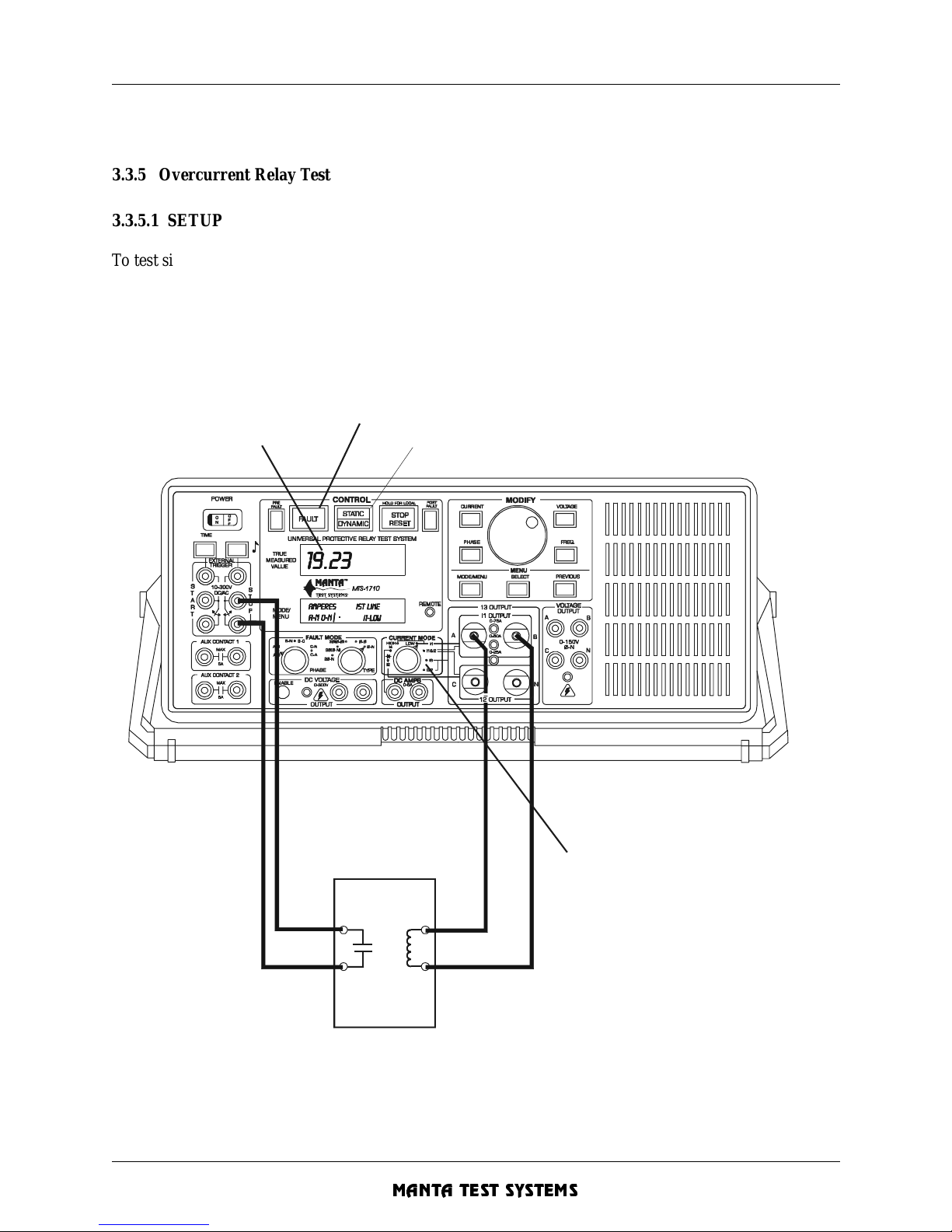
OPERATION SUMMARY - Section 3
MTS-1700 SERIES OPERATION AND REFERENCE MANUAL 3-11
CU A002 15A
MANTA TEST SYSTEMS
3.3.5 Overcurrent Relay Test
3.3.5.1 SETUP
To test single-phase overcurrent relays:
1. Connect the relay to the MTS-1710, as shown in Figure 3.4.
2. Turn off the MTS-1720, if on and connected.
3. Select I1-LOW current mode (or I1-HIGH current mode when more than 30A is required).
FIGURE 3.4 OVERCURRENT RELAY TEST SETUP
I
S
elect DYNAMIC mode to run timing test
Display opera te time
or current
Press [FAULT] to apply fault current
S
elect I1-LOW current mode for most tests.
Select I1-HIGH current mode for
instantaneo us tests requiring ov er 30 amps.
OVERCURRENT
RELAY
Page 56
OPERATION SUMMARY - Section 3
3-12 MTS-1700 SERIES OPERATION AND REFERENCE MANUAL
MANTA TEST SYSTEMS
CU A002 15A
3.3.5.2 MINIMUM PICKUP TEST.
T o check the minimum pickup level of an overcurrent relay:
1. If the MTS-1720 is on and connected, then turn it off .
2. Make test connections, as shown in Figure 3.4.
3. Press [STATI C/DYNAMIC], as required, to select STATIC operation mode.
4. Press and hold [FAULT], or short the [EXTERNAL START] cont act inputs. This holds the MTS-1710
in the fault state, indicated by the illuminated [FAULT] button.
5. Press [CURRENT] to display/adjust current.
6. Turn the [MODIFY] knob to slowly increase the current. When the relay contacts close, the [TONE]
button will light. If the audible stop trigger tone has been enabled (by pressing the [TONE] button), the
tone also will sound. The current may be adjusted as required to determine the minimum pickup level.
7. Release the [FAULT] button and remove connections to the [EXTERNAL START] inputs.
Note: A foot switch is often useful when doing this type of wor k. Connect a normally open foot switch to
the [EXTERNAL START] contact inputs, and press on the switch to apply fault voltage and
current levels. Release to return to prefault (or off) levels.
3.3.5.3 INVERSE-TIME CHARACTERISTIC TEST .
T o check the inverse-time curve of an overcurrent relay:
1. Make test connections, as shown in Figure 3.4.
2. Press [STATIC/DYNAMIC], as required, to select STATIC operation mode.
3. Press and hold [FAULT] or short the [EXTERNAL START] contact inputs. This holds the MTS-1710
in the fault state, indicated by the illuminated [FAULT] button.
4. Press [CURRENT] to display/adjust the current. Turn the [MODIFY] knob to set the test current.
5. Release the [FAULT] button and remove connections to the [EXTERNAL START] inputs.
6. Press [STATIC/DYNAMIC] to select DYNAMIC operation mode.
7. Press [FAULT] to initiate timing check.
8. When the relay operates, the [STOP/RESET] button will illuminate. The operate time and current can
be viewed by pressing [TIME] and [CURRENT] respectively. Press [STOP/RESET] to return to the
prefault state and prepare for the next test.
9. For each new value of current, repeat steps 2 to 9.
3.3.5.4 INSTANTANEOUS ELEMENT TEST.
T o check the instantaneous element of an overcurrent relay:
1. Make test connections, as shown in Figure 3.4. Note tha t, on some relays, the instantaneous e lement may
have a separate set of contacts. Select I1-HIGH current mode if more than 30A is required. Otherwise,
select I1- LOW current mode.
2. Press [STATIC/DYNAMIC], as required, to select STATIC operation mode.
3. Press [CURRENT] to display current.
Page 57
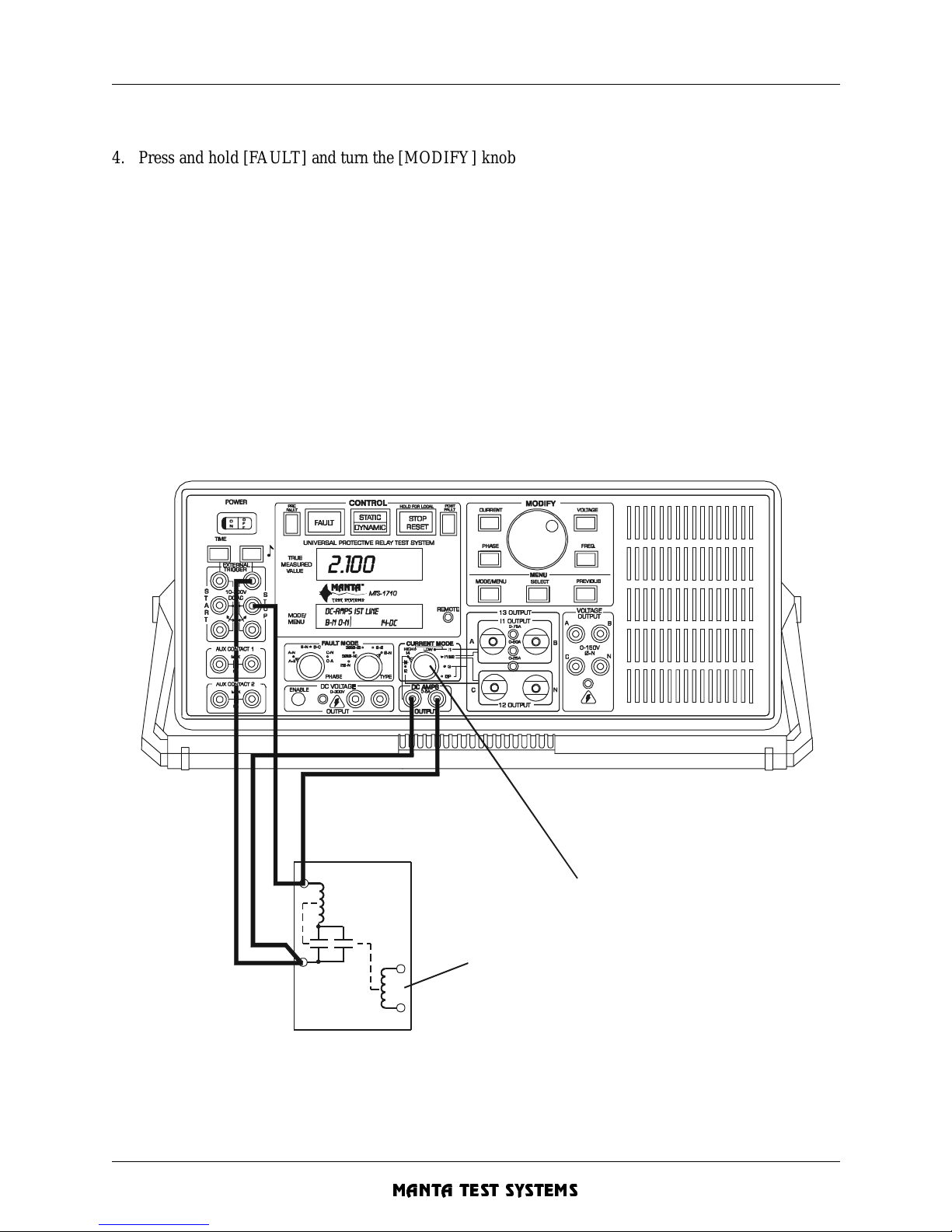
OPERATION SUMMARY - Section 3
MTS-1700 SERIES OPERATION AND REFERENCE MANUAL 3-13
CU A002 15A
MANTA TEST SYSTEMS
4. Press and hold [FAULT] and turn the [MODIFY] knob to change the current. When the relay contacts
close, the [TONE] button will light. If the audible stop trigger tone has been enabled (by pressing the
[TONE] button), the tone also will sound. Releasing the [FAULT] button at any time will turn off the
current. This allows you to make several passes at adjusting the current without overheating the relay.
You can also set the fault current without applying current to the relay using the fault current preset
feature (see Section 4.6.9).
Note: If an “OVERLOAD I1” warning appears, the relay burden may be too high. If possible, apply
current to the instant aneous element only, and bypass the timed element.
5. To time the operation of the instantaneous element, press [STATIC/DYNAMIC] to select DYNAMIC
operation mode.
6. Press [FAULT] to initiate timing check.
7. When the relay operates, the [STOP/RESET] button will illuminate . The operate time can be viewed by
pressing [TIM E ]. Pres s [STOP/ R E SET ] t o return to the pre faul t sta te and p rep ar e fo r the nex t test .
FIGURE 3.5 OVERCURRENT RELAY TARGET/SEAL-IN TEST SETUP
S
elect I4 current mode.
M
anually rotate disk and hold main contacts closed
TARGET
OP
Page 58
OPERATION SUMMARY - Section 3
3-14 MTS-1700 SERIES OPERATION AND REFERENCE MANUAL
MANTA TEST SYSTEMS
CU A002 15A
3.3.5.5 TARGET/SEAL-IN TEST.
To check the target and seal-in features of a DC current-operated target:
1. Connect the relay, as shown in Figure 3.5. Select I4-DC current mode, and static operation mode.
2. Use the current preset feature to preset the DC current to the appropriate value (usually 0.2A or 2.0A).
This is done by setting [PREFAULT] off, pressing and holding the [CURRENT] button, and adjusting
the [MODIFY] knob. Release the [CURRENT] button when done.
3. Turn [PREFAULT] on.
4. Manually rotate the induction disk fully on the relay, and hold the main contacts closed. The target and
seal-in unit should operate. This can be verified on the MTS-1710 by observing the DC current jump
from basically zero to a new value, and seeing the [TONE] button LED turn off.
5. Release the induction disk, and the seal-in unit should continue to allow the DC current to flow.
6. Turn [PREFAULT] off and observe the seal-in unit drop out. The DC current suddenly will drop to
zero, and the [TONE] button LED will turn on.
The connec tions to the exter nal stop tr igge r inp uts are on ly t o give vis ibl e/audib le ind ication of th e
contact status here. W hen the contac ts are open, a DC vo ltage (from the DC curre nt output) appe ars
across the contacts. This is sense d and the [TONE] LED (and tone , if enabled) is on. When the contac ts
close, the DC voltage drops to near zero, and the [T ONE] LED is off.
Page 59
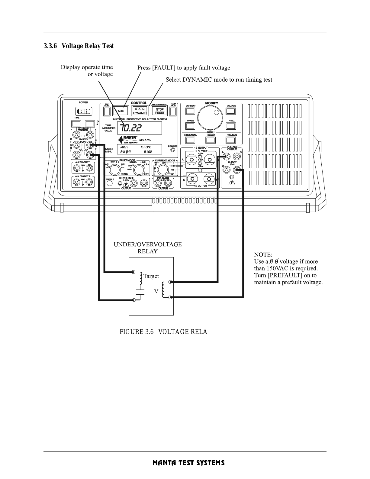
OPERATION SUMMARY - Section 3
MTS-1700 SERIES OPERATION AND REFERENCE MANUAL 3-15
CU A002 15A
MANTA TEST SYSTEMS
3.3.6 Voltage Relay Test
FIGURE 3. 6 VOLTAGE RELAY TEST SETUP
3.3.6.1 PICKUP TEST .
T o check the pickup level of an over/undervoltage relay:
1. Make test connections, as shown in Figure 3.6. Select Φ- N/A-N fault mode. If more than 150V is
required, connect the relay across A-B, and select 2Φ-N/A-B fault mode.
Page 60
OPERATION SUMMARY - Section 3
3-16 MTS-1700 SERIES OPERATION AND REFERENCE MANUAL
MANTA TEST SYSTEMS
CU A002 15A
2. Press [STATI C/DYNAMIC], as required, to select STATIC operation mode.
3. Press and hold [FAULT], or short the [EXTERNAL START] contact inputs. This holds the MTS-1710
in the fault state, indicated by the illuminated [FAULT] button.
4. Press [VOLTAGE] to display/adjust voltage.
5. Turn the [MODIFY] knob to adjust the voltage until the relay operates. When the relay contacts close,
the [TONE] button will light. If the audible stop trigger tone has been enabled (by pressing the
[TONE] button), the tone also will sound. The voltage may be adjusted, as required, to determine the
pickup level.
6. Release the [FAULT] button, and remove connections to the [EXTERNAL START] inputs.
3.3.6.2 TIMING TEST.
T o check the operation time:
1. Perform steps 1-3 of the pickup check above.
2. Press [VOLTAGE] to display/adjust voltage. Set the desired overvoltage or undervoltage level.
3. Release the [FAULT] button, and remove connections to the [EXTERNAL START] inputs.
4. If prefault voltage is desired, turn [PREFAULT] on, and set desired prefault voltage.
5. Press [STATIC/DYNAMIC] to select DYNAMIC operation mode. Press [FAULT] to initiate.
6. When the relay operates, the [STOP/RESET] button will illuminate. Press [TIME] to read the operate
time. Press [TIME] again to toggle between time in seconds/cycles. Press [STOP/RESET] to return to
the prefault state, and to prepare for the next test.
7. For each new value of voltage, repeat steps 2 to 6.
3.3.6.3 TARGET/SEAL-IN TEST.
To check the target and seal-in features of a DC current-operated target:
1. Make test connections, as shown in Figure 3.7. Select I4-DC current mode, and static operation mode.
Select Φ-N/A-N fault mode. If more than 150V is required, connect the relay across A-B and select
2Φ-N/A-B fau l t mo d e.
2. Turn [PREFAULT] on. Press [VOLTAGE] and turn the [MODIFY] knob to set the prefault voltage, as
required.
3. Press and hold the [FAULT] button, and turn the [MODIFY] knob to set the fault voltage. Release the
[FAULT] button.
4. If you want a value other than the default voltage during postfault, press [POSTFAULT], and set the
postfault vol tage.Then turn [PREFAULT] on. To verify the seal-in function, set the postfault voltage to
a value which doesn’t operate the relay.
5. Use the curr ent preset fea ture t o pres et the D C curren t (us ually 0. 2A or 2.0A). Note that the [M ODE /
MENU DISPLAY] should indicate DC-AMPS while making this setting.
6. Select dynamic operation mode. Turn [POSTFAULT] on. (This is for DC current to be on in postfault
to operate the target and seal-in).
7. Press [FAULT] to initiate.When the relay operates, the MTS-1710 will change to postfault state, the
target and seal -in should operate, and the fault voltage level will be remove d.
8. Turn [POSTFAULT] off to remove the DC current, and to release the seal-in unit.
Page 61
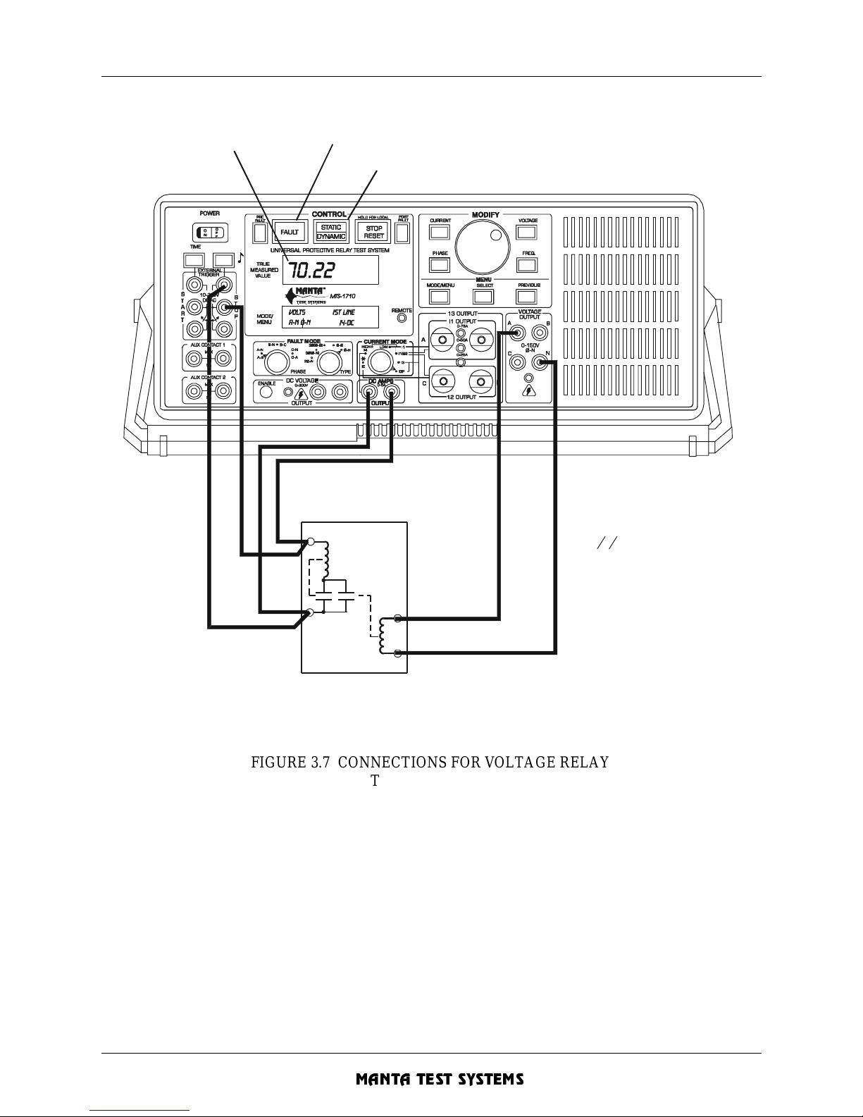
OPERATION SUMMARY - Section 3
MTS-1700 SERIES OPERATION AND REFERENCE MANUAL 3-17
CU A002 15A
MANTA TEST SYSTEMS
FIGURE 3.7 CONNECTIONS FOR VOLTAGE RELAY
TARGET/SEAL-IN TEST
3.3.7 1-Φ Impedance Relay/Directional Ov ercurrent Relay Test
These relays require a single voltage and curr ent for testin g. The I1-LOW current mode is most appropri ate
for these types of relays.
Make connections as shown on the next page. The MTS-2100 program provided with your MTS-1710 is
useful for demonstrat ing the standard tests described in this section.
S
elect DYNAMIC mode to run timing test
Display operate time
or voltage
Press [FAULT] to apply fault voltage
RELAY
NOTE:
Use a 0-0 voltage if more
than 150VAC is required.
Turn [PREFAULT] on to
maintain a prefault voltage.
UNDER/OVERVOLTAGE
TARGET
OP
Page 62
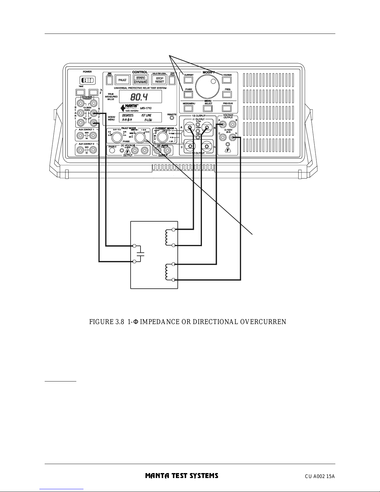
OPERATION SUMMARY - Section 3
3-18 MTS-1700 SERIES OPERATION AND REFERENCE MANUAL
MANTA TEST SYSTEMS
CU A002 15A
FIGURE 3.8 1-Φ IMPEDANCE OR DIRECTIONAL OVERCURRENT
RELAY TEST SETUP
3.3.7.1 REACH/MINIMUM PICKUP TEST.
The following procedure tests the reach of a single-phase impedance relay or minimum pickup of a
directional over current relay:
Preparation
1. If the MTS-1710 is on and connected, then turn it off .
2. Connect relay, as shown in Figure 3.8. Select Φ-N/A-N fault mode. If more than 150V is required,
connect the relay voltage input across VAB, and select 2Φ-N/A-B fault mode.
3. Select I1-LOW current mode and static operation mode. Turn [PREFAULT] on, press [CURRENT],
and adjust current to 0A.
4. Press [VOLTAGE], and set the nominal voltage.
I
V
SINGLE PHASE IMPEDANC E
OR DIRECTIONAL
OVERCURRENT RELAY
T
est connections shown
for phase-neutral,
A-N fault mode
a
nd I1-LOW current mode
Select desired parameter for adjustment
Page 63
OPERATION SUMMARY - Section 3
MTS-1700 SERIES OPERATION AND REFERENCE MANUAL 3-19
CU A002 15A
MANTA TEST SYSTEMS
Determine reach/pic kup
5. Press and hold the [FAULT] button, or short the [EXTERNAL START] contact inputs. Set the desired
test fault voltage. Press [ CURRENT] and set starting fault current (e.g. 5A). Thi s is necessary t o set the
phase angle.
6. Press [PHASE] and adjust the phase angle to the MTA or a value within the operating region.
7. Press [CURRENT] and slowly increase the current until the relay operates. For impedance relays, you
can also press [VOLTAGE] and decrease the voltage. The [TONE] button will light when the relay
contacts close. The [TONE] button also toggles an audible tone on or off.
8. For impedance relays, the reach can be displayed directly by activating the impedance display feature
(see Section 5.10.3.1).
9. To test at different angles, repeat at step 5.
10. When finished, releas e the [FAULT] button or [EXTERNAL ST ART] contact input.
3.3.7.2 MTA TEST.
The following procedure determines the ma ximum torque angle of a single -phase impedance or directional
overcurrent elemen t:
1. If you have not done so, perform steps 1-7 of the reach/minimum test above to find the pickup point at
the theoretical MTA. Increase the current slightly to move further into the region of operation.
2. Press [PHASE], and increase the phase angle until the relay opens. Record this phase angle value.
3. Adjust the phase angle to the nominal MTA. Decrease the phase angle until the relay opens again.
Record this value.
4. The measured MTA is the average of the two recorded phase angle values.
5. Release the [FAULT] button or [EXTERNAL START] contact input.
3.3.7.3 OPERATE TIME TEST.
The following procedure determines the operation time of a single-phase impedance relay or directional
overcurrent elemen t:
1. If you have not done so, perform steps 1-6 of the reach/minimum pickup test above to find the pickup
point at th e the oretical MTA. Increase the curr ent (or de creas e the vo ltage for an imp edanc e rel ay) to
the desired point for testing.
2. Release the [FAULT] button or [EXTERNAL ST ART] contact input.
3. Press [STATIC/DYNAMIC] to select dynamic operation mode. Press [FAULT] to initiate the faul t.
4. When the relay operates, the [STOP/RESET] button will illuminate. Press [TIME] to see the operation
time. Press [TIME] again to toggle between display in seconds or cycles.
5. Press [STOP/RESET] to clear and prepare for next test.
3.3.7.4 TARGET/SEAL-IN TEST
See Application Note (AN17) Section 2.5.
3.3.8 Voltage R estra i ne d Ov ercu rrent R ela y Test
The following procedure tests voltage restrained or voltage controlled overcurrent elements. The element
may or may not be directional (phase angle sensitive).
Page 64
OPERATION SUMMARY - Section 3
3-20 MTS-1700 SERIES OPERATION AND REFERENCE MANUAL
MANTA TEST SYSTEMS
CU A002 15A
3.3.8.1 MINIMUM PICKUP TEST .
Preparation
1. If the MTS-1710 is on and connected, then turn it off .
2. Connect relay, as shown in Figure 3.8. Select Φ-N/A-N fault mode. If more than 150V is required,
connect the relay voltage input across VAB, and select 2Φ-N/A-B fault mode.
3. Select I1-LOW current mode and static operation mode. Turn [PREFAULT] on, press [CURRENT],
and adjust current to 0A.
4. Press [VOLTAGE], and set the nominal voltage.
Determine pickup
5. Press and hold the [FAULT] button, or short the [EXTERNAL START] contact inputs. Set the desired
test fault voltage. Press [ CURRENT] and set starting fault current (e.g. 5A). Thi s is necessary t o set the
phase angle.
6. If the element is directional, press [PHASE] and adjust the phase angle to the MTA or a desired value
within the operating reg ion.
7. Press [CURRENT] and slowly increase the current until the relay operates. The [TONE] button will
light when the relay contact s close. The [TONE] button also toggles an audible tone on or off .
The pickup level varies with the voltage for voltage restrained/controlled overcurrent elements.
Therefore press [VOLTAGE], change the voltage and verify that the pickup level changes
appropriately.
8. When finished, release the [FAULT] button or [EXTERNAL START] contact input.
3.3.8.2 OPERATE TIME TEST.
The following procedure determines the operation time of a voltage controlled overcurrent element:
1. If you have not done so, pe rform steps 1-7 of the minimum pickup test above to find the pickup point at
the theoretical MTA.
2. Increase the current to the desired point for testing. Press [VOLTAGE], and set the desired controlling/
restraint volt age.
3. Release the [FAULT] button or [EXTERNAL ST ART] contact input.
4. Press [STATIC/DYNAMIC] to select dynamic operation mode. Press [FAULT] to initiate the faul t.
5. When the relay operates, the [STOP/RESET] button will illuminate. Press [TIME] to see the operation
time. Press [TIME] again to toggle between display in seconds or cycles.
6. Press [STOP/RESET] to clear and prepare for next test. Repeat from step 2 for each new value of
voltage and or current.
3.3.8.3 TARGET/SEAL-IN TEST.
See Application Note (AN17) Section 2.5.
3.3.9 3-Φ Impedance Relay Test
To test three-phase, three-element impedance relays, the I3 current mode should be used. This allows the
current to be routed to the phase element being tested while eliminating any change in connections.
Page 65
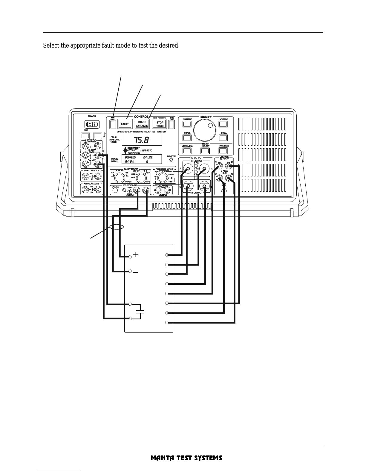
OPERATION SUMMARY - Section 3
MTS-1700 SERIES OPERATION AND REFERENCE MANUAL 3-21
CU A002 15A
MANTA TEST SYSTEMS
Select the appropriate fault mode to test the desired Φ -N, Φ -Φ or 3-Φ elements. The MTS-2100
program provided with your MTS-1710 is useful for demonstrating the standard tests described in this
section.
FIGURE 3.9 3-Φ IMPEDANCE RELAY TES T SETUP
3.3.9.1 PREPARATION.
Connect the relay and setup prefault conditions as described below:
1. If the relay is DC-powered and you’re using the DC voltage output of the MTS-1710, check the DC
voltage output before connecting the relay. This can be done by toggling the [VOLTAGE] pushbutton
until the [MO DE/ME NU DISP LAY] indicates “DC Vo lts”. If the vol tage isn’t corre ct, adj ust it via the
menu by selecting SETTINGS DCVolts in the menu. Then turn the [MODIFY] knob to position the
cursor over the desired voltage, and press [SELECT]. Press [MODE/MENU] to exit the menu. If the
DC voltage output option isn’t installed, an external DC source may be used.
DC
Supply
Va
Vb
Vc
Vn
Ia
Ib
Ic
In
U
se I3 current mode for
c
ontrols.
For DC powered
S
elect DYNAMIC mod e to run timin g te st
Press [F A U LT] to apply fault valu es
3 phase impedance relays
Select element to be
tested usin g
FAULT MODE
relays only.
T
urn [PREFAULT] on to maintain prefault values
Page 66
OPERATION SUMMARY - Section 3
3-22 MTS-1700 SERIES OPERATION AND REFERENCE MANUAL
MANTA TEST SYSTEMS
CU A002 15A
2. Connect relay as shown in Figure 3.9. Select I3 current mode and static operation mode. Turn
[PREFAULT] on, press [CURRENT], and adjust current to 0A.
3. Select
Φ-N/A-N fault mode, press [VOLTAGE], and set the nominal Φ−Ν voltage (69.28V default).
Do the same for B-N and C-N.
3.3.9.2 REACH TEST.
The following procedure te sts the reach of an impedance element at a given angle:
Preparation
1. Perform steps 1-3 in the Preparation Section (3.3.9.1).
Select fault type and phase
2. Select the desired fault type Φ-Ν, Φ-Φ, or 3-Φ elements. For Φ-N and Φ-Φ fault types, select the
desired fault phas e.
Determine reach
3. Press and hold the [FAULT] button, or short the [EXTERNAL START] contact inputs. Press
[CURRENT] and set starting fault current (e.g. 5A). This is necessary to set the phase angle.
4. Press [PHASE] and adjust the phase an gle to the MTA or desired value . Whe n using Φ-Φ and 3Φ(Φ-Φ)
fault types, it’s not necessary to account for any
30° offset. The angle displayed is the angle which
relay sees. For example, if the MTA is 75° offset, adjust the phase until the MTS-1710 reads 75°.
5. Press [VOLTAGE] and decrease the voltage until the relay operates. You can also press [CURRENT]
and increase the current. When the relay contacts close, the [TO NE] button will light. The [TONE]
button also toggles an audib le tone on or off.
6. To display reach dir ect ly, activate the imped a nc e dis pl ay featu re (see Section 5.10.3. 1) .
Repeating for other angles/elements
7. To test at different phase angles, repeat at step 4. To test other elements (A-N, B-N, C-N, A-B, B-C, CA), simply rotate the [FAULT PHASE] selector. The preset fault quantities will be immediately
applied to the new phase, providing for rapid testing. Release the [FAULT] button or [EXTERNAL
STAR T] contact input when finished.
8. To test other fault types (Φ-N, Φ-Φ, 3Φ), repeat at step 2.
3.3.9.3 MTA TEST.
The following procedure det ermines the maximum torque angle of an impedance element:
1. If you haven’t done so, perform steps 1-3 in the Preparation section (3.3.9.1).
2. If you haven’t done so, perform steps 2-5 of the reach test above to find the reach at the theoretical
MTA. Decrease the voltage, or increase the current slightly, to move the impedance further into the
region of operation.
3. Press [PHASE], and increase the phase angle until the relay opens. Record this phase angle value.
4. Adjust the phase angle to the nominal MTA. Decrease the phase angle until the relay opens again.
Record this value . Whe n using Φ-Φ and 3 Φ(Φ-Φ) fault types , it’s not necessary to account for any 30°
offset.
Page 67
OPERATION SUMMARY - Section 3
MTS-1700 SERIES OPERATION AND REFERENCE MANUAL 3-23
CU A002 15A
MANTA TEST SYSTEMS
5. The measured MTA is the average of the two recorded phase angle values.
6. Release the [FAULT] button or [EXTERNAL START] contact input.
7. To test other elements (A-N, B-N, C-N, A-B, B-C, C-A), simply rotate the [FAULT PHASE] selector
and repeat at step 2.
3.3.9.4 OPERATE TIME TEST.
The following procedure det ermines the operation time of an impedance relay element:
1. If you haven’t done so, perform steps 1-3 in the Preparation section (3.3.9.1).
2. If you haven’t done so, perform steps 2-5 of the reach test above to find the reach at the theoretical
MTA. To set the impedance to the desired percent of reach for test ing, decrease the voltage, or increase
the current.
3. Release the [FAULT] button or [EXTERNAL START] contact input. Press [STATIC/DYNAMIC] to
select dynamic operation mode.
4. Press [FAULT] to initiate the fault.
5. When the relay operates, the [STOP/RESET] button will illuminate. Press [TIME] to see the operation
time. Press [TIME] again to toggle between display in seconds or cycles.
6. Press [STOP/RESET] to clear and prepare for next test.
7. To test other elements (A-N, B-N, C-N, A-B, B-C, C-A), or zones, simply rotate the [FA ULT PHASE]
selector, and repeat at step 2 .
3.3.9.5 SWITCH-ONTO-FAULT TEST.
The following procedure determines the operation time of the switch-onto-fault feature of an impedance
relay. This procedure is the same as the timing test, except that the dynamic test is performed with prefault
off:
1. If you haven’t done so, perform steps 1-3 in the Preparation section (3.3.9.1).
2. If you haven’t done so, perform steps 2-5 of the reach test above to find the reach at the theoretical
MTA. To set the impedance to the desired percent of reach for test ing, decrease the voltage, or increase
the current.
3. Release the [FAULT] button or [EXTERNAL ST ART] contact input.
4. Turn [PREFAULT] off. Press [STATIC/DYNAMIC] to select dynamic operation mode. Press [FAULT]
to initiate the fault.
5. When the relay operates, the [STOP/RESET] button will illuminate. The relay should trip, indicating
switch-onto-f ault (if annunciation is available). Pres s [TIME] to see the operation time.
6. Press [STOP/RESET] to clear and prepare for next test.
3.3.9.6 CURRENT SUPERVISION TEST.
This test checks the curren t superv i sion lev el of a distan ce element.
1. Perform steps 1- 4 of the Reach test (Section 3.3.9.2) above.
2. While still holding in the [FAULT] button or shorting the [EXTERNAL START] contact inputs, press
[VOLTAGE], and adjust the voltage to zero. This sets the fault impedance to zero.
3. Press [CURRENT], and adjust the current to zero.
4. Now slowly increase the current. When the relay contacts close, the [TONE] button will light. At this
point, the fault current level is the current supervision level.
5. Release the [FAULT] button, or disconnect [EXTERNAL START] contact input.
6. To test other elements (A-N, B-N, C-N, A-B, B-C, C-A), simply change the fault mode, and repeat at
step 2.
Page 68
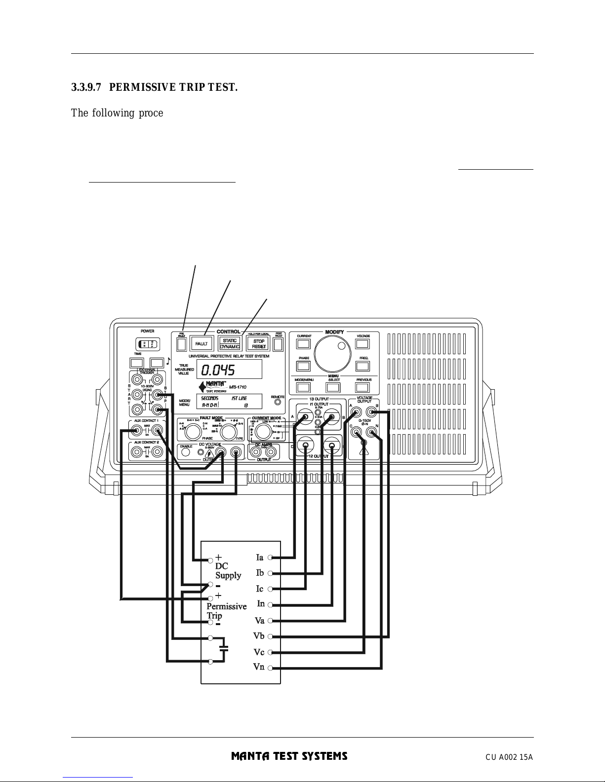
OPERATION SUMMARY - Section 3
3-24 MTS-1700 SERIES OPERATION AND REFERENCE MANUAL
MANTA TEST SYSTEMS
CU A002 15A
3.3.9.7 PERMISSIVE TRIP TEST .
The following procedure checks the basic operation of permissive trip (PUR or POR) functions of an
impedance relay. The [AUX CONTACT 1] is used to apply a DC signal to the permissive trip input to the
relay:
1. *If you haven’t done so, perform steps 1-3 in the Preparation section (3.3.9.1), except using the
connections shown in Figure 3.10.
2. If you haven’t done so, perform steps 2-5 of the reach test above to find the zone 2 reach at the
theoretical MTA. To set the impedance to the desired percent of reach for testing, decre ase the voltage,
or increase the current.
3. Release the [FAULT] button or [EXTERNAL START] contact input. Press [STATIC/DYNAMIC] to
select dynamic operation mode.
FIGURE 3.10 3-Φ IMPEDANCE RELAY PERMISSIVE TRIP TEST SETUP
S
elect DYNAMIC mode to run timing test
Press [FAULT] to apply fault values
Use I3 current mode
Select element to be
tested using FAULT MODE
controls.
T
urn [PREFAULT] on to maintain prefault values
Page 69
OPERATION SUMMARY - Section 3
MTS-1700 SERIES OPERATION AND REFERENCE MANUAL 3-25
CU A002 15A
MANTA TEST SYSTEMS
4. Press [FAULT] to initiate the fault.
5. When the relay operates, the [STOP/RESET] button will illuminate. Press [TIME] to see the operation
time. The relay should operate in the zone 1 time.
6. Press [STOP/RESET] to clear and prepare for next test.
7. Repeat steps 3-6, with the connections to the permissive trip input removed, and the relay should
operate in the zone 2 time.
8. To test other elements (A-N, B-N, C-N, A-B, B-C, C-A), or other zones, simply rotate the [FAULT
PHASE] selector, and repeat at step 2.
* Alternatively, an MTS-1730 output channel could be used to apply DC voltage to the permissive trip
input of the relay rather than the MTS-1710’s auxiliary contact output. For example, if the MTS1730’s output channel 0 is used, the following commands should be sent via the RS-232 port to close
the contacts during the fault state:
DIO,OUT0,0,1
DIO,OUT1,1,1
DIO,OUT2,0,1
3.3.9.8 TESTING SIGNAL SEND/CARRIER SEND OUTPUT.
This procedure checks the signal send/carrier send/key output operation of a distance relay with
communications-aide d accelerated tripping.
Testing the signal send/carrier send/key output is the same as testing an instantaneous distance element.
The signal send/carrier send/key output operation depends on the scheme type, as shown on the following
page:
Signal send/carrie r send/key
Scheme
output asserted for
Permissive underreach fault in Zone 1
Permissive overreach fault in Zone 2
Blocking fault in reverse Zone 3
Procedure
1. Perform steps 1-3 in the Preparation section (3.3.9.1).
2. Connect the signal send/carrier send/key output to the [EXTERNAL STOP] trigger inputs.
3. Select the appropriate fault type
Φ-Φ, Φ-N etc. Generally the test is done once for both Φ-Φ and Φ-N
to check that a carrier send is output for both phase and ground faults.
4. Press and hold
the [FAULT] button or short to the [EXTERNAL START] contact inputs. Press
[CURRENT] and set a starting fault current (e.g. 5A).
5. Press [PHASE] and adjust the phase angle to the MTA (MTA-180° for blocking scheme).
6. Press [VOLTAGE] and decrease the voltage until the signal send contact operates. You also can press
[CURRENT] and increase the current. When the conta cts close, the [TONE] button will light. Th e
[TONE] button also toggle s an audible tone on or off.
7. Veri fy that the signal send con tact closes only works for faults in the specifie d zone (s) in the table
above.
8. Set the fault voltage and current to within the operating zone.
Page 70
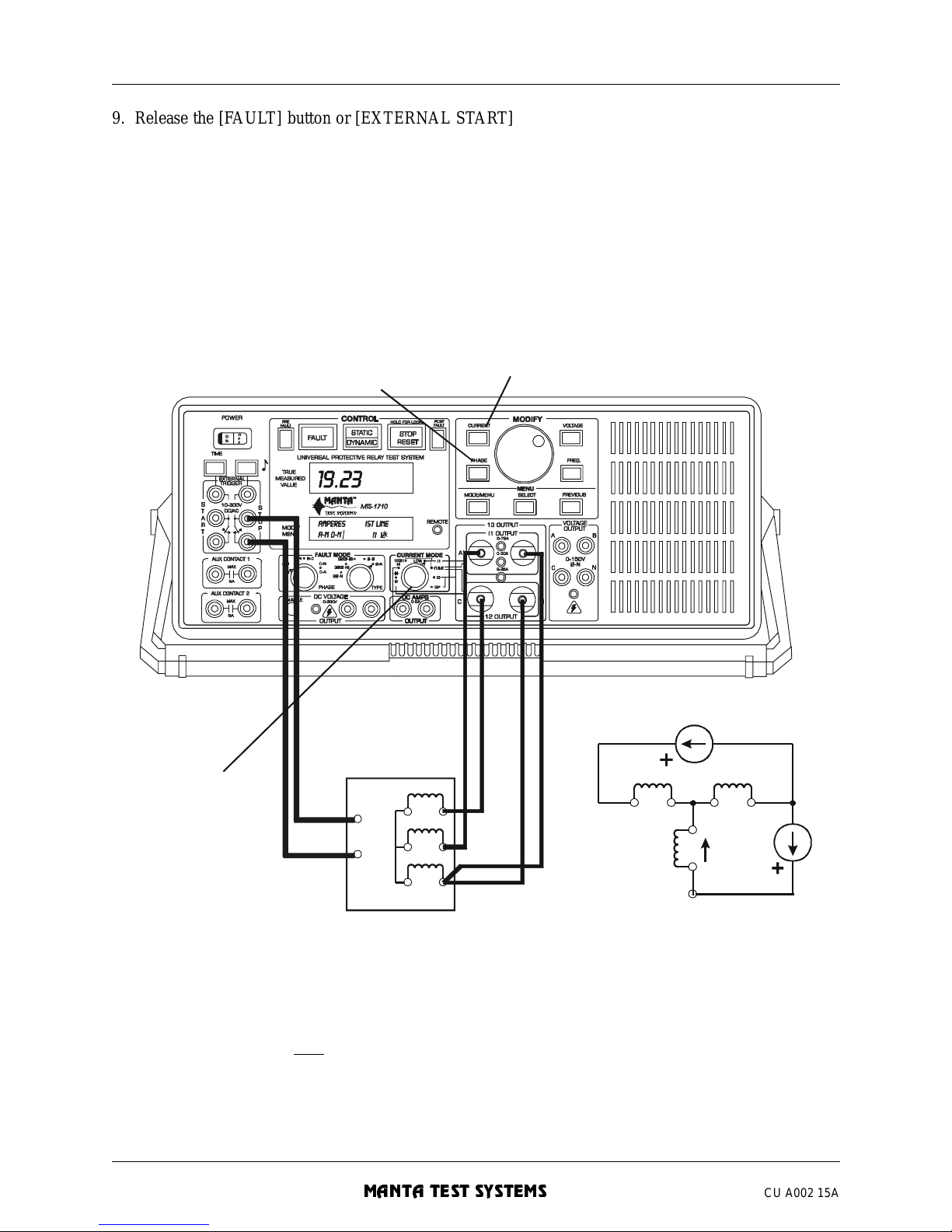
OPERATION SUMMARY - Section 3
3-26 MTS-1700 SERIES OPERATION AND REFERENCE MANUAL
MANTA TEST SYSTEMS
CU A002 15A
9. Release the [FAU LT] button or [EXTERNAL START] contact input. Select dynamic operation mode.
Press [FAULT] and time the operation of the signal send output. The operation should be virtually
instantaneous.
10. Select static operation mode again, press and hold [FAULT], and reverse the fault phase angle setting
by 180°. The signal send contact should not close.
3.3.10 Differential Relay - Three-Terminal Type
Most electromechanical current differential relays are a three-terminal type. This section describes how to
perform standard tests on this type of relay.
FIGURE 3.11 CONNECTIONS FOR THREE-TERMINA L CURRENT DIFFERENTIAL RELAYS
3.3.10.1 MINIMUM PICKUP TEST.
1. Connect the relay as shown in Figure 3.11. Select I1&I2 current mode and static operation mode.
2. Press [CURRENT] to display/adjust I1 curre nt. “I1-AMPS” sho uld be indic ated in the [MODE/MENU
DISPLAY]. Press and hold
[FAULT], and set the current to zero.
3. Press [CURRENT] again to display/adjust I2 current.
4. Slowly increase the operate current (I2) until the relay operates. Record this reading as the minimum
pickup current. Release the [FAULT] button.
OPR1R
2
DIFFERENTIAL
RELAY
P
ress [CURRENT] to toggle between I1 and I2
adjustment/display .
Press [PHASE ] to display
and adjust phase between
I1 and I2.
Select I1&I2
current mode
I1I
2
I2
R
1R2
O
P
&
Page 71
OPERATION SUMMARY - Section 3
MTS-1700 SERIES OPERATION AND REFERENCE MANUAL 3-27
CU A002 15A
MANTA TEST SYSTEMS
3.3.10.2 SLOPE TEST.
1. Connect relay, as shown in Figure 3.11. Select I1&I2 current mode and static operation mode. Turn
[PREFAULT] off.
2. Press [CURRENT] to display/adjust I1 current. “I1-AMPS” should be indicated in the [MODE/MENU
DISPLAY]. Press and hold
[FAULT], and increase the current to the desired restraint current value.
3. Press [CURRENT] again to display/adjust I2 current. Increase the operate current to 1A. Press
[PHASE], and check the phase between I1&I2. Adjust if necessary to
0°. Press [CURRENT], and
decrease the current to 0A.
4. Slowly increase the operat e cu rren t (I2 ) u nt il th e rel a y op er at es. R eco rd t h e I1 an d I2 cu rr en t r eadi ng s.
Release the [FAULT] button.
5. Use the required formula to calculate slope. If the simple I2÷I1 formula applies, this can displayed
directly. Select DISP RATIOS CURRENT-RATIOS I2÷I1 via the menu. If the I2÷(I1+I2÷2) formula
applies, select DISP RATIOS CURRENT-RATIOS SLOPE I2÷((2I1+I2)÷2) in the menu.
6. To repeat at different values of restraint, repeat at step 2.
3.3.10.3 OPERATE TIME TEST.
1. If you haven’t done so, perform steps 1-3 of the slope test above.
2. Press [CURRENT] to display/adjust I2 current. Increase the operate current to the desired value.
Release the [FAULT] button.
3. Select dynamic operation mode. Press [FAULT] to perform the timing test.
4. When the relay operates, the [STOP/RESET] button will illuminate. Press [TIME] to see the operation
time. Press [TIME] again to toggle between display in seconds or cycles.
5. Press [STOP/RESET] to clear and prepare for next test.
3.3.10.4 HARMONIC RESTRAINT TEST.
1. Connect relay, as shown in Figure 3.11. (The relay doesn’t need to be connected to the MTS-1710 I1
output for this test). Select I2-HARMONIC current mode and static operation mode. Turn
[PREFAULT] on.
2. Press [CURRENT] to display/adjust I2 current. “I2-AMPS” should be indicated in the [MODE/MENU
DISPLAY]. Increase the cur rent to the desired test v alue (usually equa l to the tap value). The rel ay
should be operated*.
3. Press [CURRENT] to display/adjust %harmonic. “%-HARM” should be indicated in the [MODE/
MENU DISPLAY]. Increase the %harmonic until the relay restrains to determine the %harmonic
restraint value . The harmonic value default s to second harmonic . For testing at higher harmonic s, press
[FREQ] and turn the [MODIFY] knob to select the desir ed value .
NOTE: For halfwave harmonic testing, select DC-Amps.
4. Turn [PREFAULT] off.
*NOTE: For latching trip elements, it may be necessary in step 2 to first set the %-harmonic to a high
value to restrain operation, and then to increase the fundamental current (I2-AMPS). Then,
in step 3, the % harmonic should be decreased until the relay operates.
For relays with harmonic restraint elements which are traditionally tested with half wave
rectified AC, such as the GE BDD 15/16 and ABB HO, see important additiona l information
in Application Note 23.
Page 72
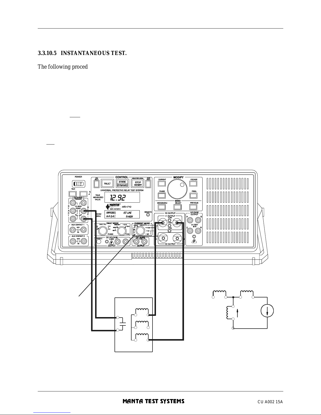
OPERATION SUMMARY - Section 3
3-28 MTS-1700 SERIES OPERATION AND REFERENCE MANUAL
MANTA TEST SYSTEMS
CU A002 15A
3.3.10.5 INSTANTANEOUS TEST.
The following procedure des cribes how to test the unrestrained instantane ous ove rcurrent element:
1. Depending upon the current requ ired, one of two connections can be used for the current. If 30A or less
is required, the current coils can be left connected as shown in Figure 3.11, and I1&I2 current mode
used. If more than 30A is required, connect as shown in Figure 3.12. For the latter, select I1-HIGH
current mode.
2. Select static operation mode, and turn [PREFAULT] off.
3. Press and hold
the [FAULT] button.
4. If using the I1&I2 current mode method, press [CURRENT] to display/adjust I1-AMPS, and adjust I1
to zero. Press [CURRENT] again, and increase I2 until the relay operates.
OR
If using the I1-HIGH current mode method, press [CURRENT], and increase the current until the relay
operates.
FIGURE 3.12 INSTANTANEOUS TEST FOR THREE-TERMINAL
CURRENT DIFFERENTIAL RELAYS
OPR1R
2
DIFFERENTIAL
RELAY
Select I1-HIGH
current mode
+
I
1
I1
R
1R2
O
P
Page 73
OPERATION SUMMARY - Section 3
MTS-1700 SERIES OPERATION AND REFERENCE MANUAL 3-29
CU A002 15A
MANTA TEST SYSTEMS
5. Release the [FAULT] button at any time to turn off the cur rent. This allows you to make several passes
at adjusting the current without overheating the relay. As well, you can set the fault current without
applying current to the rel ay, using the fault current preset feature (see Section 4.6.9).
6. To time the operation of the instantaneous element, select dynamic operation mode, a nd press [FAULT]
to initiate.
7. When the relay operates, the [STOP/RESET] button will illuminate . The operate time can be viewed by
pressing [TIME]. Press [STOP/RESET] to return to the prefault state, and to prepare for the next test.
3.3.10.6 TARGET/SEAL-IN TEST.
The following procedure describes how to test a current-operated target and seal-in unit on a differential
relay:
1. A MTS-1720 is required for this test. Refer to Section 9.3.3 for proper connection and setup of the
MTS-1720. Connect the relay, as shown in Figure 3.13. Select I4-DC current mode and static
operation mode. Turn [PREFAULT] on.
2. Use the current preset feature to preset the DC current to the appropriate value (usually 0.2A or 2.0A).
This is done by setting [PREFAULT] off, pressing and holding the [CURRENT] button, and adjusting
the [MODIFY] knob. Release the [CURRENT] button when done.
3. Select
B-N/Φ−Ν fault mode. Display the AC current by pressing [CURRENT] until the upper left
corner of the [MODE/MENU DISPLAY] reads “AC-AMPS”.
4. Press and hold
[F AULT]. T ur n the [MODIFY] knob to increase t he current until the rela y operates. The
target (and seal- in unit, if available) also should operate. The [TONE] button LED should turn off.
5. Press [CURRENT] to display/adjust the DC current. I ncrease the DC current to 0.2A or 2A, as required,
to operate the targe t.
6. Release the [FAULT] button to remove the AC current.
7. If a seal-in unit is included, turn [PREFAULT] off a nd observe the seal-in unit dropout. The DC current
will drop to zero and the [TONE] button LED will turn on.
Page 74
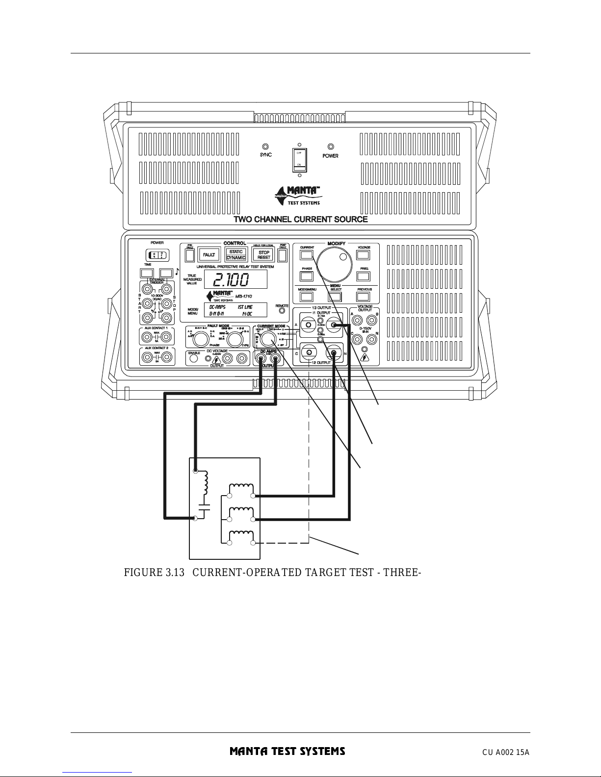
OPERATION SUMMARY - Section 3
3-30 MTS-1700 SERIES OPERATION AND REFERENCE MANUAL
MANTA TEST SYSTEMS
CU A002 15A
FIGURE 3.13 CURRENT-OPERATED TARGET TEST - THREE-TERMINAL
TYPE DIFF’L RELAY
3.3.11 Differential Relay - Independent Coil Type
Many solid state current differential relays have independent coils for the two current inputs. This section
describes how to perform the standard tests on this type of relay:
TARGET
S
elec t I 4 current mo de.
0
-25A LED indicates AC available
Toggle [CURRENT] to
adjust/d isp lay DC/AC
current.
OP
R1
R2
O
ptional
2.100
OFF
ON
Page 75
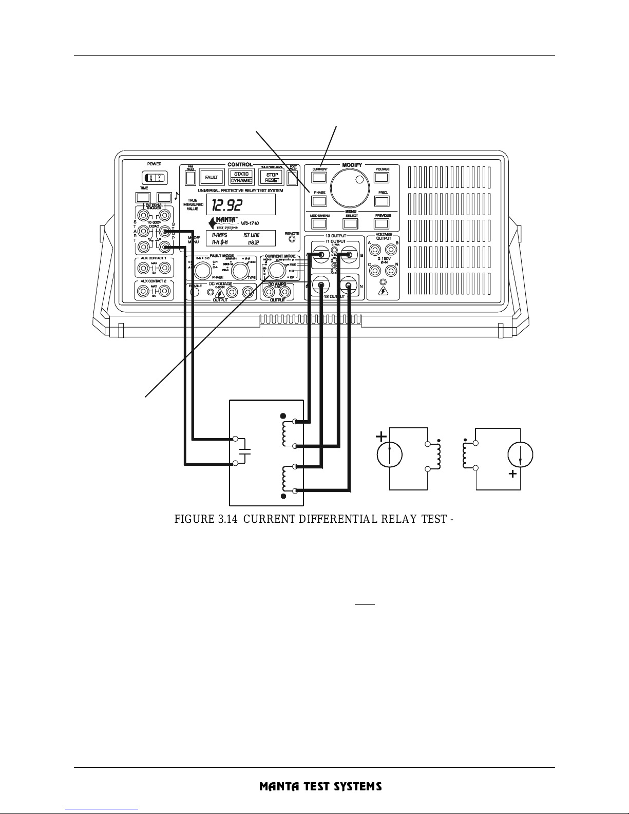
OPERATION SUMMARY - Section 3
MTS-1700 SERIES OPERATION AND REFERENCE MANUAL 3-31
CU A002 15A
MANTA TEST SYSTEMS
FIGURE 3.14 CURRENT DIFFERENTIAL RELAY TEST -
INDEPENDENT COIL TYPE
3.3.11.1 MINIMUM PICKUP TEST.
1. Connect the relay as shown in Figure 3.14. Select I1-LOW current mode and static operation mode.
2. Press [CURRENT] to display/adjust I1 current. Press and hold
[FAULT].
3. Slowly increase the current (I1) until the relay operates. Record this reading as the minimum pickup
current. Release the [FAULT] button.
3.3.11.2 SLOPE TEST.
1. Connect relay as shown in Figure 3.14. Select I1&I2 current mode and static operation mode. Turn
[PREFAULT] off.
2. Press [CURRENT] to display/adjust the I1 current. “I1-AMPS” should be indicated in the [MODE/
MENU DISPLAY]. Press and hold [FAULT], and increase the current to the desired nominal value.
DIFFERENTIAL
RELAY
P
ress [CURRENT] to toggle between I1 and I2
adjustment/display.
Press [PHASE] to display
and adjust phase between
I1 and I2.
Select I1&I2
current mode
I1I
2
P
hase angle between
I
1 & I2 is normally
set to 0°
Page 76
OPERATION SUMMARY - Section 3
3-32 MTS-1700 SERIES OPERATION AND REFERENCE MANUAL
MANTA TEST SYSTEMS
CU A002 15A
3. Press [CURRENT] again to display/adjust the I2 current. Increase to the nominal value. Press
[PHASE], and set the phase between I 1&I2. Adjust if necessary. This is typically 0°, but may be 30° or
-30° for transformer differential relays which protect Y-∆ transformers. The relay should now be
operated.
4. Slowly decrease the operate current ( I2) until the relay operates. Record the I1 and I2 current readings.
Release the [FAULT] button.
5. Use the required formula to calculate slope. If the standard | I1-I2|÷((I1+I2)÷2) formula applies, this can
be directly displaye d. Sele ct DISP RATIOS CURRENT-RATIOS SLOPE |I1-I2|÷((I1+I2)÷2) via the
menu.
6. To repeat at different values of restraint, repeat at step 2.
3.3.11.3 OPERA TE TIME TEST .
1. If you haven’t done so, perform steps 1-3 of the slope test above.
2. Press [CURRENT], and adjust either the I1 or I2 current to the desired test value. The relay should
now be operated. Release the [FAULT] button.
3. Select dynamic operation mode. Press [FAULT] to perform the timing test.
4. When the relay operates, the [STOP/RESET] button will illuminate. Press [TIME] to see the operation
time. Press [TIME] again to toggle between display in seconds or cycles.
5. Press [STOP/RESET] to clear, and to prepare for the next test.
3.3.11.4 HARMONIC RESTRAINT TEST.
Using the test connections shown in Fi gure 3.14, follow the procedure given in Section 3.3.10 .4.
3.3.11.5 INSTANTANEOUS TEST.
Use the test connections , as shown in Figure 3. 14.
If more than 30A is required, the I1-HIGH current mode should be used. Follow the same basic procedure
as outlined in Section 3.3.10.5.
3.3.11.6 TARGET TEST.
To test current-operated targets on this type of relay, follow the procedure outlined in Section 3.3.10.6,
except connect the B-N and C-N current outputs of the MTS-1710 to the two independent current coils.
3.3.12 Synchronizing/Re closing or Synchrocheck Relay
These types of relays are tested using the synchronizing mode of the MTS-1710.
The following sections describe how to perform standard tests. The SYNCSCOPE computer program
provided with your MTS-1710 is useful (but not a necessity) for demonstrating these tests .
Page 77
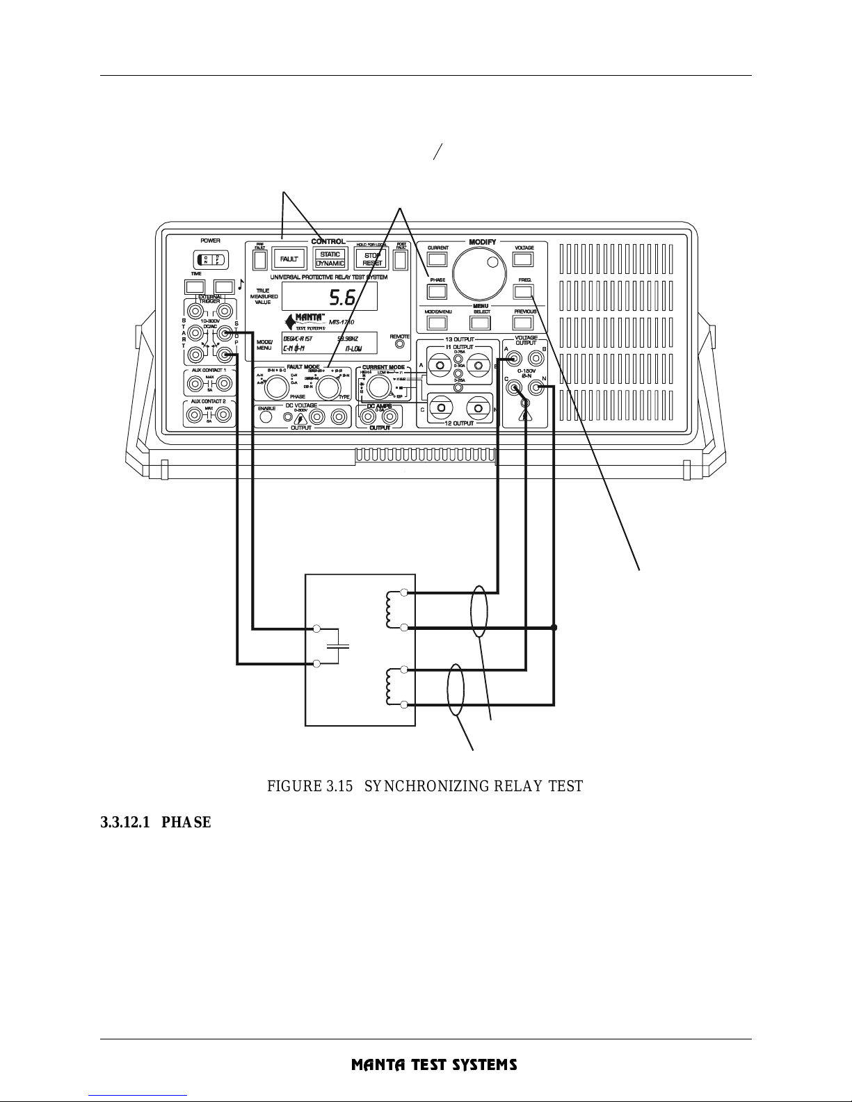
OPERATION SUMMARY - Section 3
MTS-1700 SERIES OPERATION AND REFERENCE MANUAL 3-33
CU A002 15A
MANTA TEST SYSTEMS
FIGURE 3.15 SYNCHRONIZING RELAY TEST
3.3.12.1 PHASE ANGLE LIMIT TEST.
1. Make test connections, as shown in Figure 3.15.
2. Select Φ-N/C-N fault mode, Il-LOW current mode. Turn
[PREFAULT] off . If the upper right corne r of
the [MODE/MENU DISPLAY] doesn’t indicate “LINE”, press [FREQ] to toggle to line reference
mode.
3. Using the menu, select SETTINGS MODES FREQ SYNCHRONIZING ON to enable synchronizing
mode.
4. Turn [PREFAULT] on and, if required, check the A-N and C-N voltage s by pressing [VOLT AGE], and
selecting A-N and C-N fault phase. Adjust if necessary.
GEN
(or BUS)
BUS
(or LINE)
SYNCHRONIZING
OR SYNCHROCHECK
RELAY
V
a at fault frequency setting
V
c at prefault frequency setting
S
elect 0-N C-N fault mode and press
[PHASE] to display phase between
Vc & Va
Select variable frequency
reference mode
Select DYNAMIC operation mode
and press [FAULT] to initiate
Page 78
OPERATION SUMMARY - Section 3
3-34 MTS-1700 SERIES OPERATION AND REFERENCE MANUAL
MANTA TEST SYSTEMS
CU A002 15A
5. Select Φ-N/C-N fault mode, and press [PHASE]. Note that the [MODE/MENU DISPLAY] indicates
this is the phase between Va and Vc. Press [PHASE] to toggle between 0-360° and 0-±180° display
modes.
6. Increase and decrease the phase angle to determine the phase angle limit window. The relay should be
operated within the window.
3.3.12.2 VOLTAGE LIMIT TEST.
1. If you haven’t done so, perform steps 1-4 above (Section 3.3.12.1).
2. Select
Φ -N/C-N f a u lt mode, a n d press [ P H A S E]. Adj u s t the pha s e between Va a nd V c to zer o .
3. Press [VOLTAGE]. Increase and decrease the voltage to determine the voltage limit window. The relay
should be operated within the window.
3.3.12.3 SLIP FREQUENCY LIMIT TEST .
1. Make test connections, as shown in Figure 3.15.
2. Select
Φ-N/C-N faul t mo d e , I1-L O W current m od e. Turn [P REFAULT] off. If the upper right corner
of the [MODE/MENU DISPLAY] indicates “LINE”,
press [FREQ] to toggle to variable frequency
reference mode.
3. Using the menu, select SETTINGS MODES FREQ SYNCHRONIZING ON to enable synchronizing
mode.
4. Turn [PREFAULT] on and, if required, check the A-N and C-N voltage s by pressing [VOLT AGE], and
selecting A-N and C-N fault phase. Adjust if necessary.
5. Press [FREQ], and set the bus (Vc) frequency.
6. Select dynamic operation mode and press [FAULT].
While in fault state, the fault frequency displayed is the generator (Va) frequency. Vc stays fixed at the
prefault (bus) frequency. Starting from a high value of frequency, slowly decrease until the relay
operates. The indicated frequency , mi nus the prefault (bus) frequency, is the slip frequency limit.
3.3.12.4 BREAKER ADVANCE TIME CHECK.
1. If you haven’t done so, perform steps 1-6 above (Section 3.3.12.3). Don’t press reset before continuing
with step 2 below. If the Stop/Reset button is not lit, repeat steps 1-6 above.
2. Press [PHASE]. This displays the angle between the bus and generator voltage at the time the relay
operated. Press [PHASE] to toggle between 0-360° and 0-±180° display modes.
3. Using the menu, select SETTINGS MODES FREQ BRKR-ADV to activate breaker advance time
screen.
4. Turn the [MODIFY] knob until =0.00° is displayed, and the breaker advance time is shown.
Alternatively, turn the [MODIFY] knob to the known circuit breaker advance time, and the
Φ=xxx.x
will indicate the phase angle at the tim e of breaker closure.
3.3.12.5 SYNCHRONIZING ELEMENTS WITH POSITIVE SEQUENCE VOLTAGE
SUPERVISION
Some synchronizing elements may have positive sequence voltage supervision. In this case, Va and Vb
should be used, and may have to be increased in amplitude to generate enough positive sequenc e voltage to
enable the syn chro ni zi ng element.
Page 79
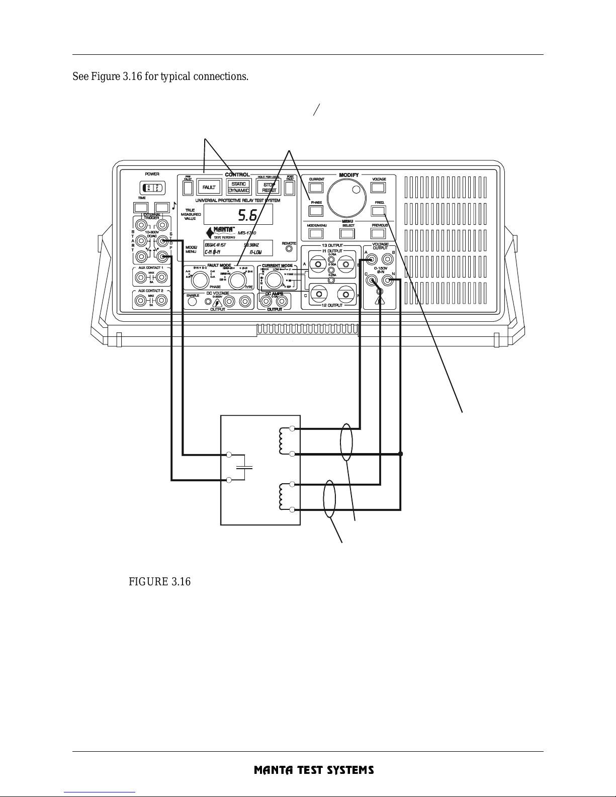
OPERATION SUMMARY - Section 3
MTS-1700 SERIES OPERATION AND REFERENCE MANUAL 3-35
CU A002 15A
MANTA TEST SYSTEMS
See Figure 3.16 for typical connections.
FIGURE 3.16 CONNECTIONS FOR SYNCHRONIZING ELEMENTS WITH
POSITIVE SEQUENCE VOLTAGE SUPERVISION
3.3.13 Ground Fault Overvoltage Relay
This type of relay uses a voltage element to sense generator zero sequence current, and often has an
undervoltage i nhibit element. This means that two voltages--on e 3rd-harmonic, and one at the fundamental
frequency, are required.
GEN
(or BUS)
BUS
(or LINE)
SYNCHRONIZING
OR SYNCHROCHECK
RELAY
V
a at fault frequency setting
V
c at prefault frequency setting
S
elect 0-N C-N fault mode and press
[PHASE] to display phase between
Vc & Va
Select variable frequency
reference mode
Select DYNAMIC operation mode
and press [FAULT] to initiate
Page 80
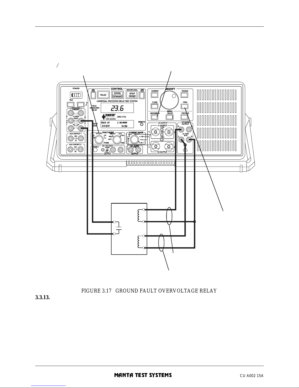
OPERATION SUMMARY - Section 3
3-36 MTS-1700 SERIES OPERATION AND REFERENCE MANUAL
MANTA TEST SYSTEMS
CU A002 15A
FIGURE 3.17 GROUND FAULT OVERVOLTAGE RELAY
3.3.13.1 SETUP.
1. Select static operation mode and turn [PREFAULT] off. Connect the relay, as shown in Figure 3.17.
2. Using the menu, select SETTINGS MODES FREQ SYNCHRONIZING ON to enable synchronizing
mode. This mode allows Vc to be fixed at the fundamental while the other outputs may be at a
harmonic frequency.
3. Turn [PREFAULT] on, and sele ct Φ-N/C-N fault mode. Note that the frequency reading is the
fundamental (60 Hz or 50 Hz).
4. Press [VOLTAGE], and set the inhibit voltage for the 27S element above the inhibit level.
59N
& 27N
(3rd harmonic)
27S
GROUND FAULT
OVERVOLTAGE
RELAY
V
a at 3rd harmonic or fundamental
Vc at fundamental frequency
Select 0-N C-N or A-N to display/adjust
corresponding voltage
Select frequency and
turn [MODIFY] to select
harmonic
Enable synchronizing mode via menu
Page 81
OPERATION SUMMARY - Section 3
MTS-1700 SERIES OPERATION AND REFERENCE MANUAL 3-37
CU A002 15A
MANTA TEST SYSTEMS
3.3.13.2 OVERVOLTAGE PICKUP TEST.
To check the pickup level of the 59N element:
1. If you haven’t done so, perform steps 1-4 above (Section 3.3.13.1).
2. Select
Φ-N/A-N fault mode. If the [MODE/MENU DISPLAY] doesn’t show VOLTS in the upper left
corner, press [VOLTAGE].
3. Pr ess and hold [FAULT], or short the [EXTERNAL START] contact inputs. This holds th e MTS-1710
in the fault state, indicated by the illuminated [FAULT] button.
4. Turn the [MODIFY] knob to increase Va (fundamental) until the relay operates. When the relay
contacts close, the [TONE] button will light. If the audible stop trigger tone has been enabled (by
pressing the [TONE] button), the tone also will sound. The voltage may be adjusted, as required, to
determine the pickup level.
5. Release the [FAULT] button, and remove the connections to the [EXTERNAL START] inputs.
3.3.13.3 OVERVO LTAGE TIMING TEST.
T o check the operation time:
1. Perform steps 1-2 of the pickup check above.
2. Press and hold
[FAULT], and turn the [MODIFY] knob to set the desired overvoltage level.
3. Release the [FAULT] button.
4. Select dynamic operation mode, turn [PREFAUL T] on, and press [FAULT] to initiate.
5. When the relay operates, the [STOP/RESET] button will illuminate. Press [TIME] to read the operate
time. Press [TIME] again to toggle between time in seconds/cycles. Press [STOP/RESET] to return to
the prefault state, and to prepare for the next test.
6. For each new value of voltage, select static operation mode, and repeat steps 2-6.
3.3.13.4 3RD HARMONIC UNDERVOLTAGE TEST.
To check the pickup level of the 3rd harmonic undervoltage element:
1. If you haven’t done so, perform the same steps as in Section 3.3.13.1.
2. Select
Φ-N/A-N f ault m o d e . Pre s s [FREQ] , a n d turn t he [M ODIF Y ] k n ob to s e lect 3 rd harm o n ic.
3. If the [MODE/MENU DISPLAY] doesn’t show VOLTS in the upper left corner, press [VOLTAGE].
4. Pr ess and hold
[FAULT], or short the [EXTERNAL START] contact inputs. This holds the MTS-1710
in the fault state, indicated by the illuminated [FAULT] button.
5. Turn the [MODIFY] knob to adjust Va (3rd-harmonic) until the relay operates. When the relay contacts
close, the [TONE] button will light. If the audible stop trigger tone has been enabled (by pressing the
[TONE] button), the tone also will sound. The voltage may be adjusted, as required, to determine the
pickup level.
6. Release the [FAULT] button, and remove the connections to the [EXTERNAL START] inputs.
3.3.13.5 UNDERVOLTAGE INHIBIT TEST.
T o check the inhibit of the 3rd-harmonic undervolta ge element by the supervising undervoltage elem ent:
Page 82
OPERATION SUMMARY - Section 3
3-38 MTS-1700 SERIES OPERATION AND REFERENCE MANUAL
MANTA TEST SYSTEMS
CU A002 15A
1. If you haven’t done so, perform steps 1- 4 of Section 3.3.13.1.
2. Select
Φ-N/A-N fault mode. If the [MODE/MENU DISPLAY] doesn’t show, VOLTS in the upper left
corner, press [VOLTAGE].
3. Turn the [MODIFY] knob to lower Va (3rd-harmonic) until the relay operates. When the relay contacts
close, the [TONE] button will light. If the audible stop trigger tone has been enabled (by pressing the
[TONE] button), the tone also will sound.
4.
Change the fault mode to Φ-N/C-N. Adjust the inhibi t voltage lower until the relay restrains to find the
threshold for the inhibit element.
3.3.14 Frequency Relay Test
3.3.14.1 PICKUP TEST.
T o check the pickup level of an over/underfreque ncy ele ment:
1. The test connections are the same as those for a voltage relay (see Figure 3.6). Select
Φ-N/A-N fault
mode. If more than 150V is required, connec t the relay across A-B, and select
2Φ-N/A-B fault mode.
2. Press [STATIC/DYNAMIC], as required, to sele ct STATIC operation mode.
3. Press [FREQ] once or twice, as required, to toggle the frequency reference mode from line to variable.
The annunciation in the upper right of the [MODE/MENU DISPLAY] will change from “LINE” to a
specific frequency (defaults to your system frequency 60.000Hz or 50.000Hz).
4. Press [VOLTAGE] to display/adjust voltage. Turn [PREFAULT] on, and set the desired prefault
voltage.
5. Press and hold
[F AULT], or short the [EXTERNAL START] contact inputs. This holds the MTS-1710
in the fault state, indicated by the illuminated [FAULT] button.
6. Turn the [MODIFY] knob to adjust the voltage for the fault state (generally the same as prefault).
7. Press [FREQ] to display/adjust frequency. Turn the [MODIFY] knob to adjust the frequency for the
fault state. When the relay contacts close, the [TONE] button will light. If the audible stop trigger tone
has been enabled (by pressing the [TONE] button), the tone also will sound. The frequency may be
adjusted, as required, to determine the pickup level.
8. Release the [FAULT] button, and remove connections to the [EXTERNAL START] inputs.
3.3.14.2 TIMING TEST.
To check the operation time of an over/underfrequency element:
1. If you haven’t done so, perform steps 1-4 of the pickup check above.
2. Press and hold
[F AULT], or short the [EXTERNAL START] contact inputs. This holds the MTS-1710
in the fault state, indicated by the illuminated [FAULT] button.
3. Turn the [MODIFY] knob to adjust the voltage for the fault state (generally the same as prefault).
4. Press [FREQ] to display/adjust frequency. Set the desired fault frequency.
5. Release the [FAULT] button, and remove connections to the [EXTERNAL START] inputs.
6. Turn the [MODIFY] knob to set a specific prefault frequency if desired.
7. Press [STATIC/DYNAMIC] to select DYNAMIC operation mode. Press [FAULT] to initiate.
8. When the relay operates, the [STOP/RESET] button will illuminate. Press [TIME] to read the operate
time. Press [TIME] again to toggle between time in seconds/cycles. Press [STOP/RESET] to return to
the prefault state, and to prepare for the next test.
Page 83
OPERATION SUMMARY - Section 3
MTS-1700 SERIES OPERATION AND REFERENCE MANUAL 3-39
CU A002 15A
MANTA TEST SYSTEMS
9. For each new value of frequency, repeat steps 2 and 4 to 8.
3.3.14.3 TARGET/SEAL-IN TEST.
To check the target and seal-in features of a DC current-operated target:
1. Connect relay, as in Figure 3.7. Select I4-DC current mode.
2. If you haven’t done so, perform steps 2-4 of the pickup check above.
3. Turn [PREFAULT] on, press [FREQ], and adjust the frequency until the relay operates.
4. Press [CURRENT], and adjust the DC current to 0.2A or 2A, as required, to opera te the target.
5. To test the seal-in feature, adjust the frequency back to normal, and the contacts should remain closed
until the DC current is removed.
Note: If the above adjustments are made in the FAULT state rather than prefault, a complete dynamic
test can be performed which simulates real world operation.
3.3.14.4 UNDERVOLTAGE INHIBIT TEST.
To check the undervoltage inhibit function:
1. If you haven’t done so, perform steps 1- 4 of the picku p check in Section 3.3.14.1.
2. Turn the [MODIFY] knob to adjust the voltage to a level below the inhibit setting.
3. Press [FREQ], and adjust the frequency to a value which would normally cause the relay to trip. The
relay should restrain from operating ([TONE] led stays off).
4. Press [VOLTAGE] and increase the voltage. The relay should trip when the voltage reaches the inhibit
level. This step can be done in the dynamic operation mode to freeze the readings at the time of the
trip, if desired.
3.3.14.5 FREQUENCY RA TE-OF-CHANGE TEST.
To check a freq uen cy rat e-o f- ch ang e el em en t:
1. If you haven’t done so, perform steps 1-6 of the timing test in Section 3.3.14.2. The initial fault
frequency (st art of the ramp) will be the frequency you had set in the FAULT state. This can also be set
via the menu using the SETTINGS RAMP FREQ INITIAL selection. This frequency is generally the
same as the prefault.
2. Press [MODE/MENU], and set up the ramp end frequency and ramp rate via the SETTINGS RAMP
FREQ FINAL and SETTINGS RAMP FREQ RATE selections. Exit the menu by pressing [MODE/
MENU].
3. Press [STATIC/DYNAMIC] to select DYNAMIC operation mode. Press [FAULT] to initiate.
4. When the relay operates, the [STOP/RESET] button will illuminate. Press [TIME] to read the operate
time. Press [TIME] again to toggle between time in seconds/cycles. Press [STOP/RESET] to return to
the prefault state, and to prepare for the next test.
5. This test should be repeated at ramp rates slightly above and below the element’s ∆f/∆t setpoint.
Repeat steps 2-4 for each new ramp rate.
(Note: You can actually initiate the fault with the menu still active. This allows you to modify the
ramp rate for successiv e trials without having to r e-enter and e xit the menu. See Section 5. 1.2
for a description of this feature).
Page 84
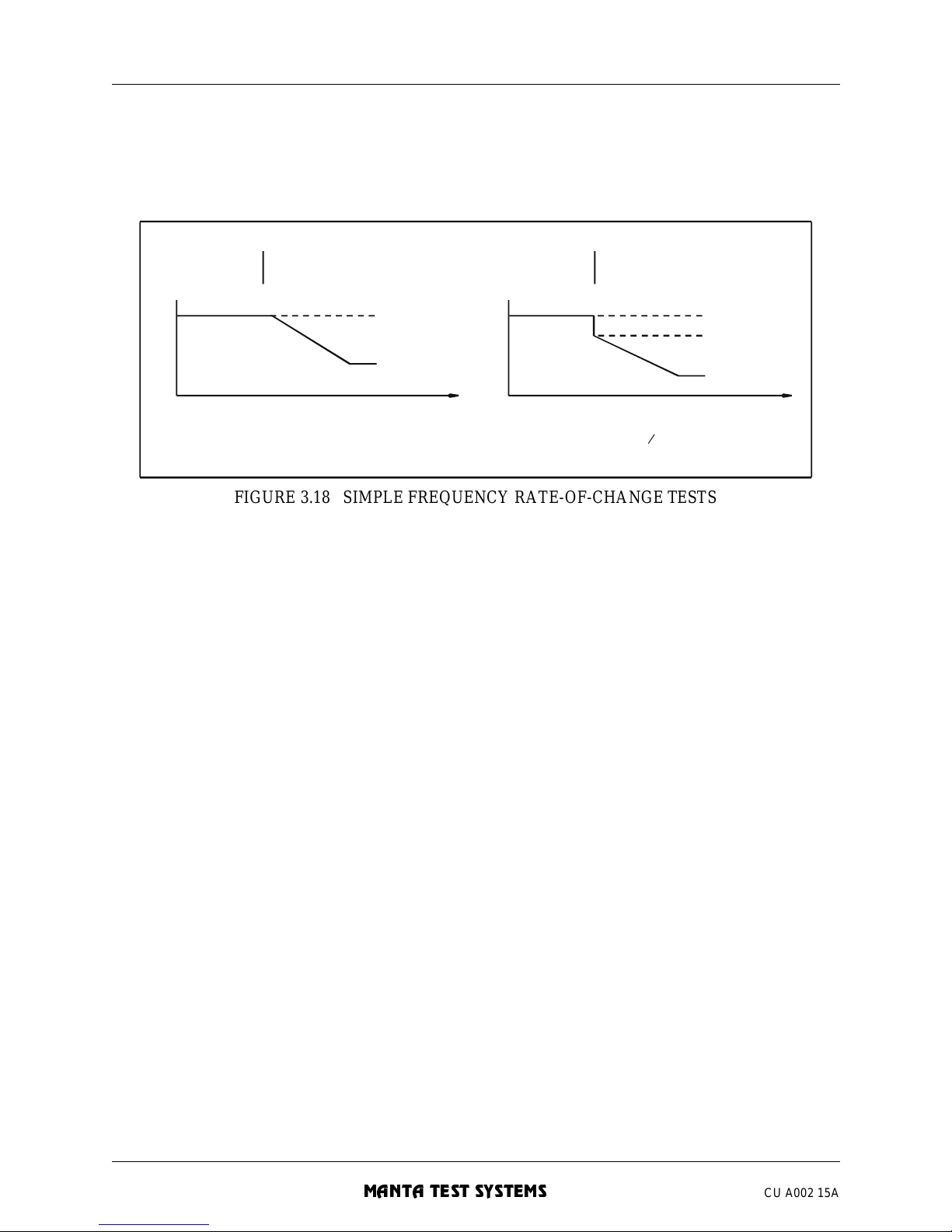
OPERATION SUMMARY - Section 3
3-40 MTS-1700 SERIES OPERATION AND REFERENCE MANUAL
MANTA TEST SYSTEMS
CU A002 15A
FIGURE 3.18 SIMPLE FREQUENCY RATE-OF-CHANGE TESTS
3.3.15 DC Auxiliary/Time-Delay Re lay Test
3.3.15.1 PICKUP TEST.
T o check the pickup level of an DC auxiliary or time-delay element:
1. NOTE: To avoid damage to the relay, set the DC voltage to off before connecting. This can be done
by pressing the [MODE/MENU] key to enter the menu, then selecting SETTINGS DCVolts
OFF using the [SELECT] button and [MODIFY] knob. Press [MODE/MENU] again to exit
the menu.
2. Connect the relay, as in Figure 3.19.
3. Press [STATI C/DYNAMIC], as required, to select STATIC operation mode.
4. If desired, press [VOLTAGE] once or twice, as require d, to toggle the [VALUE DISPLAY] to DC volts.
The annunciation in the upper left of the [MODE/MENU DISPLAY] will change to “DCVolts”.
5. Press the [MODE/MENU] key to enter the menu. Then select SETTINGS DCVolts CONTINUOUSADJUST. Turn the [MODIFY] knob to slowly increase the voltage until the relay operates (or drops
out for an undervoltage element). When the relay contacts close, the [TONE] button will light.
6. Press [MODE/MEN U ] aga in to exi t the men u .
F
AULTPREFAULT
(a) Prefault frequency=initial fault frequency
f
t
final fault
frequency
prefault/
initial fault
frequency
frequency
initial fault
frequency
final fault
t
f
(
b) Prefault frequency=initial fault frequency
PREFAULT FAULT
prefault
frequency
Page 85
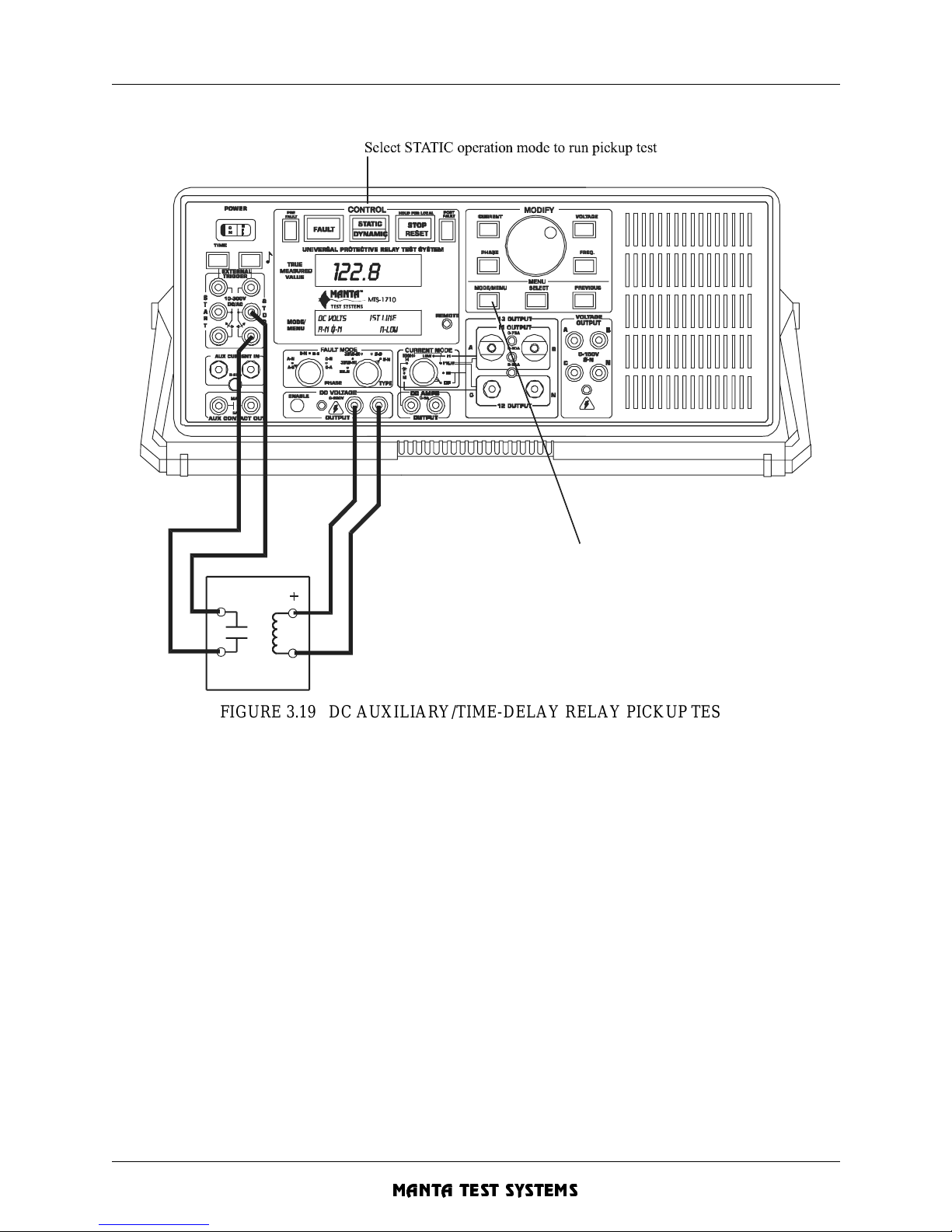
OPERATION SUMMARY - Section 3
MTS-1700 SERIES OPERATION AND REFERENCE MANUAL 3-41
CU A002 15A
MANTA TEST SYSTEMS
FIGURE 3.19 DC AUXILIARY/TIME-DELAY RELAY PICKUP TEST
NOTE: It’s possible to perform thi s test with the same conne ctions as for the timing test below, providing
that the t est is perfo rmed in t he FAULT s tate, and that the l ead con necting to t he extern al start
trigger (red) input is temporarily disconnected.
3.3.15.2 PICKUP TIMING TEST .
To check the operation time of a DC auxiliary or time-delay element (This procedure assumes a normally
open relay contacts) :
1. Connect the relay, as in Figure 3.20.
2. Press the [MODE/MENU] key to enter the menu. Then select SETTINGS DCVolts CONTINUOUSADJUST using the [SELECT] button and [MODIFY] knob. Turn the [MODIFY] knob to set the test
voltage.
3. Next go to the SETTINGS MODES TIMER menu, and select EXTERNAL timer start mode. (The
reason for this is explained in Section 5.3.2).
4. Press [MOD E /ME N U] ag ai n to ex it the me n u.
5. Press [STATIC/DYNAMIC], as required, to select DYNAMIC operation mode. Press [FAULT] to
initiate the test .
TIME-DELAY
RELAY
Set DC voltage via menu.
DC AUXILIARY/
Page 86
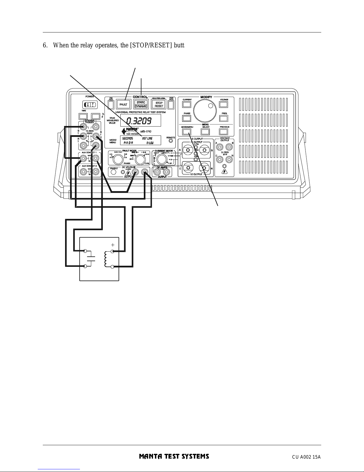
OPERATION SUMMARY - Section 3
3-42 MTS-1700 SERIES OPERATION AND REFERENCE MANUAL
MANTA TEST SYSTEMS
CU A002 15A
6. When the relay operates, the [STOP/RESET] button will illuminate. Press [TIME] to read the operate
time. Press [STOP/RESET] to return to the prefault state.
FIGURE 3.20 DC AUXILIARY/TIME-DELAY RELAY TIMING TEST
3.3.15.3 DROPOUT TIMING TEST .
T o measure the dropout time of a DC auxiliary relay (with normally open contacts):
1. Set the auxiliary contact type to NC (i.e. closed in prefault, open in fault state) via the SETTINGS
MODES AUX-CONTCT AUX_CONTACT_1 NC selection in the front panel menu.
2. Proceed as described in Section 3.3.15.2 above.
3.4 SETTINGS MAP
Due to the large number of settings which may be programmed on the MTS-1710, the following map may
be a useful guide.
This may be used to record the settings required for testing a particular device or relay. Each of these
settings is explained in detail in Section 4.
Select DYNAMIC operation mode to run timing test
Press [FAULT] to start timing test
Select External Start
timer mode via menu
TIME-DELAY
RELAY
Set DC voltage via menu.
DC AUXILIARY/
Page 87
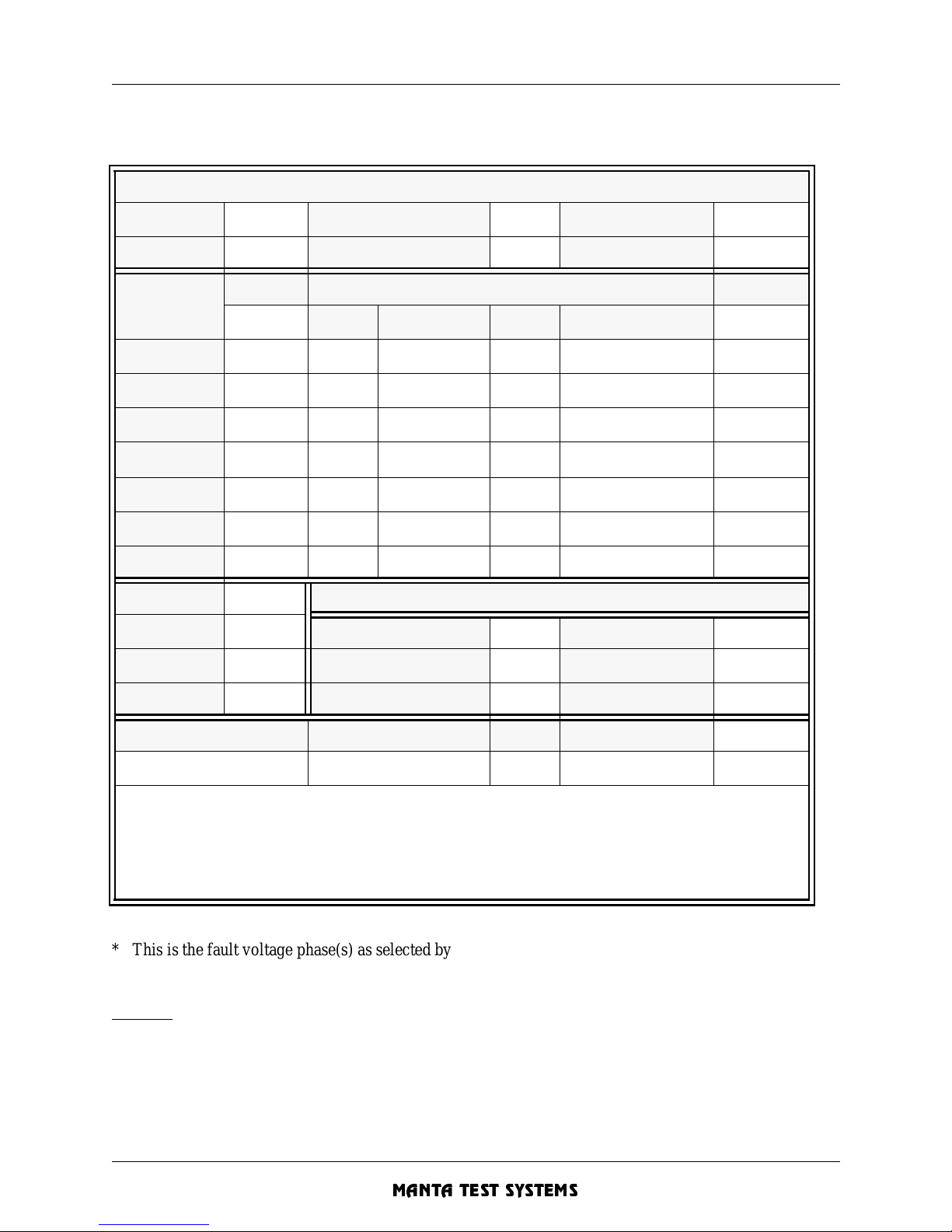
OPERATION SUMMARY - Section 3
MTS-1700 SERIES OPERATION AND REFERENCE MANUAL 3-43
CU A002 15A
MANTA TEST SYSTEMS
* This is the fault voltage phase (s) as selected by th e FAULT TYPE and FAULT PHASE selection. It may
be VAN, VBN, VCN, VAB, VBC, VCA or V-3Φ .
Example
: The map on the next page gives an example of the settin gs map testing of the Φ-Φ A-B
element of a 3Φ impedance relay.
MTS-1710 Settings Map
Fault Type Operation mode
Freq. reference mode
Fault Phase
Current mode Harmonic
Parameter
PREFAULT
FAULT
POSTFAULT
ON/OFF Initial Ramp Rate
Duration
Final
ON/OFF
VAN [V]
- - - - -
VBN [V]
- - - - -
VCN [V]
- - - - -
V____ * [V]
I1 or I3[A]
Phase [deg]
Freq. [Hz ]
I2 current [A] Special Modes and Settings (via menu)
I2 %harmonic Timer Start Mode
INT/EXT
Fault incidence angle
I4 [DC amps] Dynamic Meas. Mode Synchronizing mo de ON/OFF
Phase Sequence +ve/-ve Auto-reclose delay
Relay Type being tested Ty pe o f test Date User
Notes:
Page 88
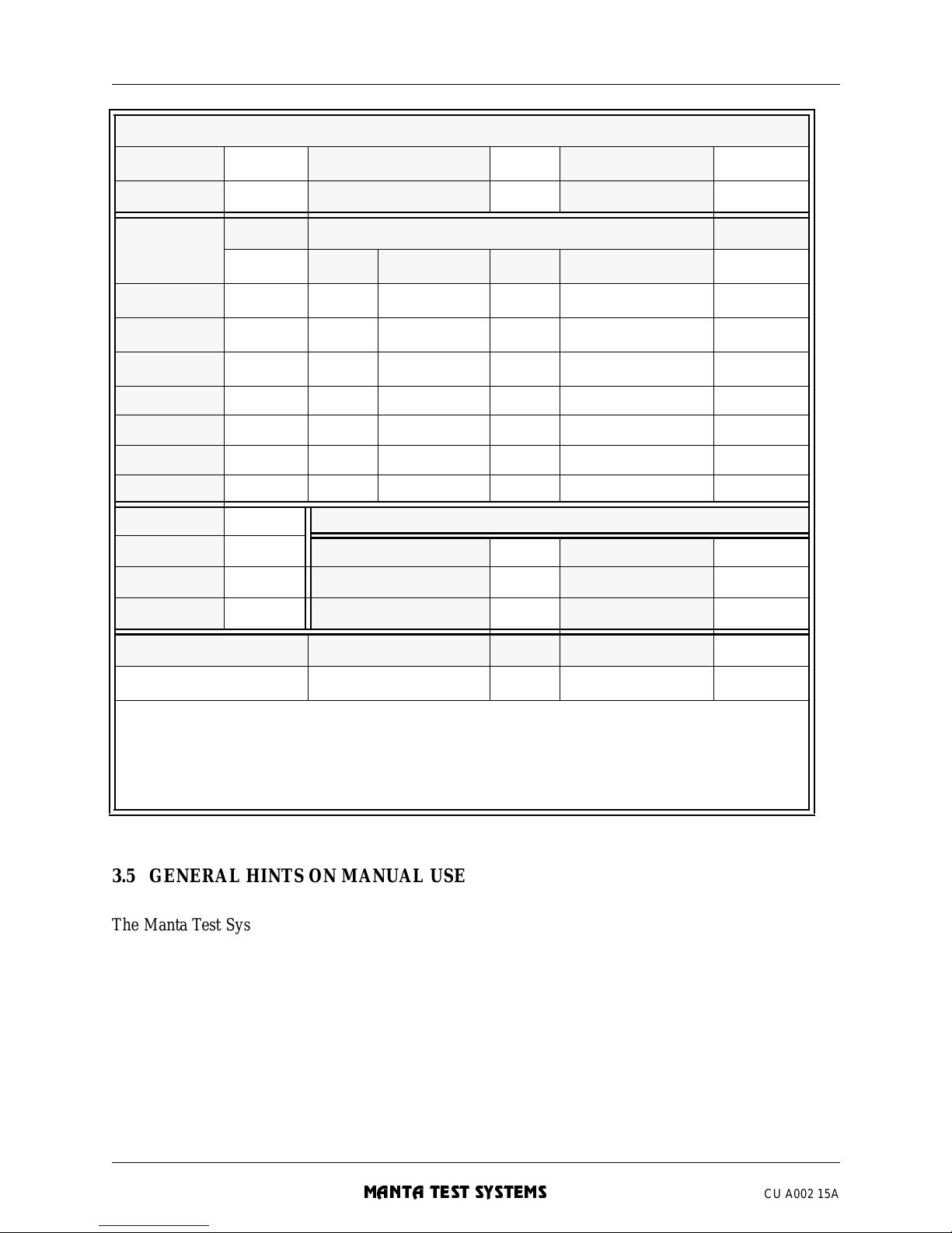
OPERATION SUMMARY - Section 3
3-44 MTS-1700 SERIES OPERATION AND REFERENCE MANUAL
MANTA TEST SYSTEMS
CU A002 15A
3.5 GENERAL HINTS ON MANUAL USE
The Manta Test Systems MTS-1710 differs in usage from conventional relay test systems in many areas.
The following hints will help new user s become familiar with the MTS-1710:
MTS-1710 Settings Map Example
Fault Type Φ-Φ Operation mode
STATIC
Freq. reference mode LINE
Fault Phase
A-B
Current mode I3 Harmonic 1
Parameter
PREFAULT
FAULT
POSTFAULT
ON Initial Ramp Rate
Duration
Final
OFF
VAN [V] 69.3
- - - - -
VBN [V] 69.3
- - - - -
VCN [V] 69.3
- - - - -
VAB [V] 120.0 variable off off N/A N/A
I1 or I3[A] 1.0 5.0 off off N/A N/A
Phase [deg] 75.0 75.0 off off N/A N/A
Freq. [Hz ] N/A N/A off off N/A N/A
I2 current [A] N/A Special Modes and Settings (via menu)
I2 %harmonic N/A Timer Start Mode
INT
Fault incidence angle RANDOM
I4 [DC amps] N/A Dynamic Meas. Mode AUTO Synchronizing mode OFF
Phase Sequence +ve Auto-reclose delay 0.0
Relay Type being tested Ty pe o f test Date User
KD-4
Φ-Φ reach
Notes: Vary the fault voltage VAB until the relay operates. To test other phase-to-phase el ements, change the fault
phase selection, and adjus t phase angle. Lower voltage until relay operates.
Page 89
OPERATION SUMMARY - Section 3
MTS-1700 SERIES OPERATION AND REFERENCE MANUAL 3-45
CU A002 15A
MANTA TEST SYSTEMS
1. Selecting Settings.
Select the major mode settings be fore setting parameters, such as current, voltage and phase angle.
In general, follow the settings map (Section 3.4) from top to bottom in setting up the instrument.
There are some settings which depend upon previous settings being made correctly (especially ramping
parameters). For each parameter (voltage, current, phase, frequency), there may be a prefault, fault and
postfault setting.
Watch the pushbuttons in the CONTROL section of the front panel to determine the present state (see
Section 4.1).
2. Current Mode
.
Always select th e desired current mode before a djusting current or phase angle . See Section 4.6 for curre nt
mode selection guide.
3. True Measured Value Display
.
The [VALUE DISPLAY] shows true measured values. This means that current must be flowing in a closed
circuit in the load for a value to appear.
Similarly, a current must be flowing to obtain a phase reading when adjusting phase.
4. Fault Mode Selectors and Voltage, Current, Phase Adjustments
.
The [FAULT PHA SE ] and [FAULT TYPE] sel ecto rs allow s imp lified s etu p for s tandard faults.
Simply select the fault type and phase, and voltage adjustment will adjust the faulting voltage(s), current
adjustment will adjust the appropriate phase current(s), and phase angle adjustments will adjust the
appropriate phase angle(s).
Always select the desire d frequency reference mode and harmonic before making phase adjustments.
5. Use of prefault and fault states
.
Be sure to develop the habit of applying fault voltages and currents in the FAULT state (i.e. [FAULT]
button depressed in the sta tic operation mode).
Most users tend to overus e the prefault state for testing. The y’re then confused in setting up a dynamic te st
involving prefault and fault. Using the fault state allows you to quickly remove high fault currents to
prevent damage to the relay. It also allows you to immediately perform a timing test after the relay’s
operate point is determi ned.
When testing distance relays, using the fault state for faults will prevent switch-onto-fault trips in normal
testing of distance elements. A user will also find it easier to learn operation with the MTS-1720, in which
prefault and fault current settings and operation is slightly different from operation with the MTS-1710
alone.
Page 90
OPERATION SUMMARY - Section 3
3-46 MTS-1700 SERIES OPERATION AND REFERENCE MANUAL
MANTA TEST SYSTEMS
CU A002 15A
Section 4 provides details on a ll these operational aspects.
The MTS-2100 computer program provided with your MTS-1710 is also very helpful as a learning and
demonstration aid. Please refer to the documentation provided with MTS-2100 for use .
Page 91
DETAILED OPERATION - Section 4
MTS-1700 SERIES OPERATION AND REFERENCE MANUAL 4-1
CU A002 15A
MANTA TEST SYSTEMS
DETAILED OPERATION
4.1 FAULT STATES
The MTS-1710 operates in one of three fault states indicated by the [FAULT] and [STOP/RESET] button
lights as follows:
.
The prefault state
simulates the healthy inputs to the relay prior to the fault occurrence. The fault state
simulates the i nputs to the re lay during a fault c ondit ion. The postfault sta te simulates the inputs to the relay
after the fault condit ion and relay operation.
The MTS-1710 can outpu t differe nt vo ltage and current le vels, phase, a nd frequ ency i n each of the prefault ,
fault and postfault sta tes.
4.2 OPERATION MODES
Operation within the three fault states is governed by the selected operation mode, which may be STATIC
or DYNAMIC. Select the operation mode by pressing the [STATIC/DYNAMIC] button.
4.2.1 Static Operation Mode
In the static operation mode (s tatic mode), the outputs are normally in the prefault sta te.
When a closed contact or voltage is present on the [EXTERNAL START] trigger inputs, or
the [FAULT]
button is depressed, the output is in the fault state. This is normally used to initially set fault conditions.
Note that the trigger action (closed contact, voltage, or depressing [FAULT]) must be maintained to hold
the MTS-1710 in the fault state. Trans itions between the two states is depicted in the followi ng diagram:
FAULT light STOP/RESET light Fault state
off off PREFAULT
ON off FAULT
off ON POSTFAULT
Uses of the STATIC operation mode Uses of the DYNAMIC operation mode
Pickup checks
Quick go/no-go tests
Adjustments of any settings
“Static” relay test ing
All ti med te sts
Dynamic test
Any test involving ramping and/or duration
Pulsed output (response time) test
Reading hold/freeze
Two-wire pulse timing
Page 92
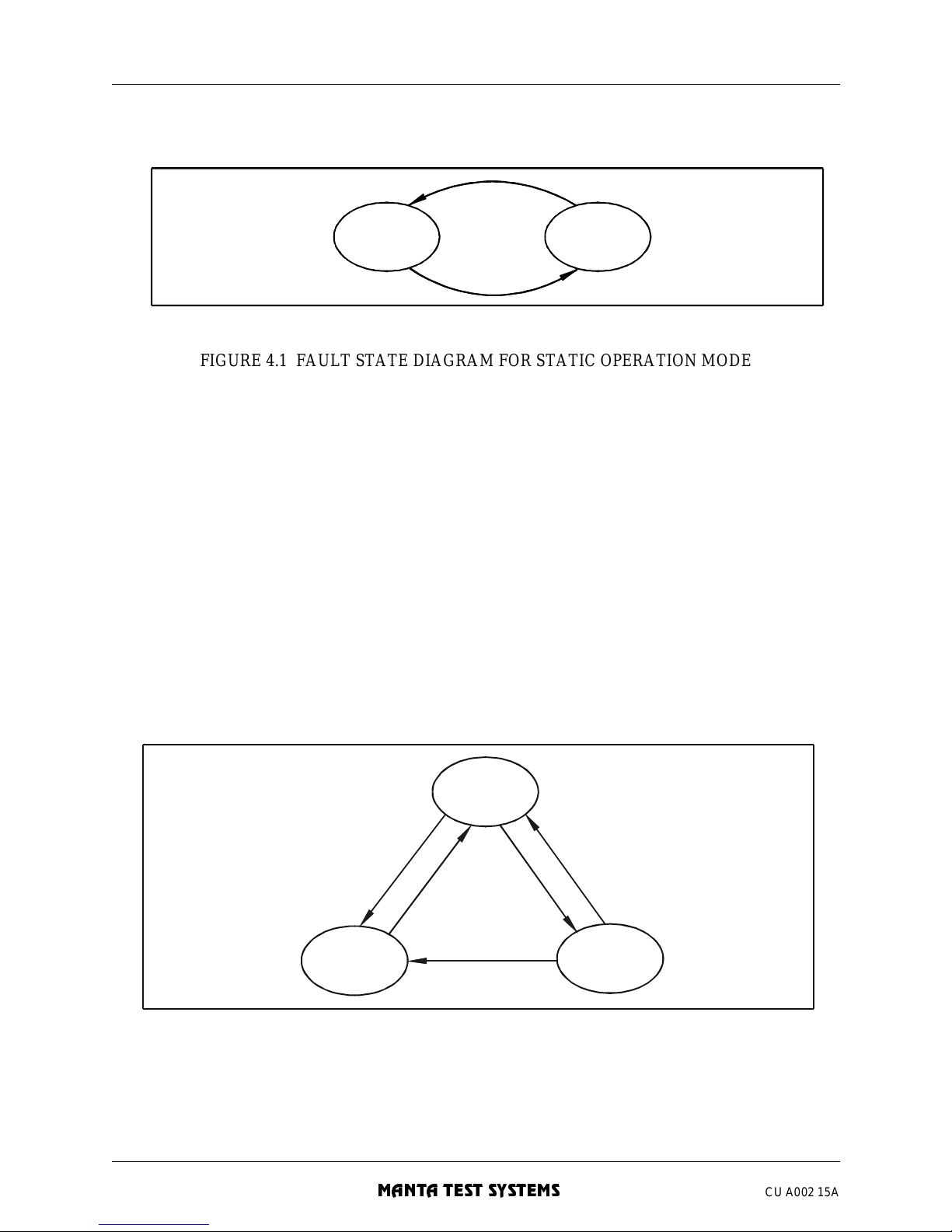
DETAILED OPERATION - Section 4
4-2 MTS-1700 SERIES OPERATION AND REFERENCE MANUAL
MANTA TEST SYSTEMS
CU A002 15A
FIGURE 4.1 FAULT STATE DIAGRAM FOR STATIC OPERATION MODE
Note that, in static operation mode, only one of the [PREFAULT], [FAULT] or [POSTFAULT] buttons
may be illuminated at a time. The illuminated button indicates which settings (prefault, fault or postfault)
are being adjusted and displa ye d.
4.2.2 Dynamic Operation Mode
The dynamic operation mode (dynamic mode) allows execution of a complete simulation from prefault to
fault, and then to postfault states.
Transition between these three sta tes is controlled by the [EXTERNAL START] and [EXTERNAL STOP]
trigger inputs, and the [FAULT] and [STOP/RESET] buttons. In the dynamic operation mode, the trigger
actions only need to be momentary to latch the MTS-1710 into the next fault state.
The state trans itio n diag ra m is sho w n be low :
FIGURE 4.2 FAULT STATE DIAGRAM FOR DYNAMIC OPERATION MODE
F
AULT
PREFAULT
[FAULT] button on
or closed contact
or voltage sensed
on START TRIGGER
[FAULT] button off
and open contact
and no voltage
on START TRIGGER
S
TOP TRIGGER
R
E
S
E
T
S
T
A
R
T
T
R
I
G
G
E
R
S
T
O
P
T
R
I
G
G
E
R
R
E
S
E
T
POSTFAULT
F
AULT
PREFAULT
Page 93
DETAILED OPERATION - Section 4
MTS-1700 SERIES OPERATION AND REFERENCE MANUAL 4-3
CU A002 15A
MANTA TEST SYSTEMS
In normal application, the MTS-1710 begins in PREFAULT state. A start trigger action will change the
MTS-1710 to the FAULT state.
A start trigge r action may include pressi ng the [FAULT] button, a transition on the [EXTERNAL START]
trigger inputs, an RS-232C STR command, or an a uxiliary start signal from the optional digital input ports.
While in the FAULT state, all start trigger actions will be ignored.
Now a stop trigger action will change the MTS-1710 to the POSTFAULT state. A stop trigger action can
originate from a transition on the [EXTERNAL STOP] trigger inputs, and RS-232C STP
command, or an
auxiliary stop signa l from the optional digital input ports.
While in the POSTFAULT state, all further start and stop trigger actions are ignored, preventing the MTS1710 from re-entering a FAULT state.
Now, only a reset actio n will restor e the MTS-1710 to t he PREFAULT state. The re set action may be cause d
by pressing the [STOP/RESET] button, or by the RS-232C RES
comman d.
Changing from dynamic to static operation mode also will cause a reset action, retur ning the MTS-1710 to
the PREFAULT state if it was previously in the FAULT or POSTFAULT state.
4.2.3 Blinking Indicators in Dynamic Mo de
Note that, in dynamic operation mode, one or more of the [PREFAULT], [FAULT] or [POSTFAULT]
buttons may be illuminated at a time. This is due to the fact that the prefault and postfault voltage/current
may be turned on or off (see Section 4.4).
If the prefault or postfault levels are armed to be on, its corresponding pushbutton wil l be illuminated. As a
visual aid, if the output levels are turned on in a particular state, and the MTS-1710 is in the corresponding
state, the corresponding button will blink.
For example, if the operation mode is dynamic, and the [PREFAULT] button is lit, the [POSTFAULT]
button isn’t lit, and the [FAULT] button is blinking, then the MTS-1710 is in the fault state, with live
outputs, prefault outputs are set to on, and postfault outputs are set to off.
4.3 CHARACTERISTICS OF FAU LT STATES
PREFAULT
FAULT
POSTFAULT
V & I outputs at pref ault settings
(or off if prefaul t set off)
V & I outputs at fault settings
V & I outputs at postfault
settings
(or off if postfault set off)
Timer=0.0sec Timer running Timer reading frozen
Normal read ing speed Fast reading spee d
(Dynamic operation mode only) *
All readings frozen at thei r
value when stop trigger
occurred
AUX contacts open** AUX contacts closed** AUX contacts open**
Page 94
DETAILED OPERATION - Section 4
4-4 MTS-1700 SERIES OPERATION AND REFERENCE MANUAL
MANTA TEST SYSTEMS
CU A002 15A
* NOTE: In the FAULT state, in dynamic operation mode, all measurements are updated at four
times the normal rate. This allows rapid changes of voltage, current, frequency and phase
to be captured. The normal rate (for 60Hz outputs) is approximately four readings per
second for voltage and current measurements, and two readings per second for frequency
and phase measurements. For information on very high speed measurements, see Sections
5.7 and 5.14.1.
**NOTE: It’s possible to change the func tion and the logic of the auxili ary contact out put (see Sect ion
5.15).
4.4 OUTPUT LEVELS
The voltage/current output in the prefault and postfault states may be set on/off by toggling the
[PREFAULT] and [POSTFAULT] respectivel y.
To set PREFAULT outputs on/off:
Press [STATIC/DYNAMIC] to select dynamic operation mode. Press [PREFAULT], as required, to
illuminate or turn off the [PREFAULT] button.
To set POSTFAULT outputs on/off:
Press [STATIC/DYNAMIC] to select dynamic operation mode. Press [POSTFAULT], as required, to
illuminate or turn off the [POSTFAULT] button.
In the dynamic operation mode, the dynamic test may be run with four combinations of prefault/postfault
V&I set on/off. This is shown in the chart on the next page:
Page 95
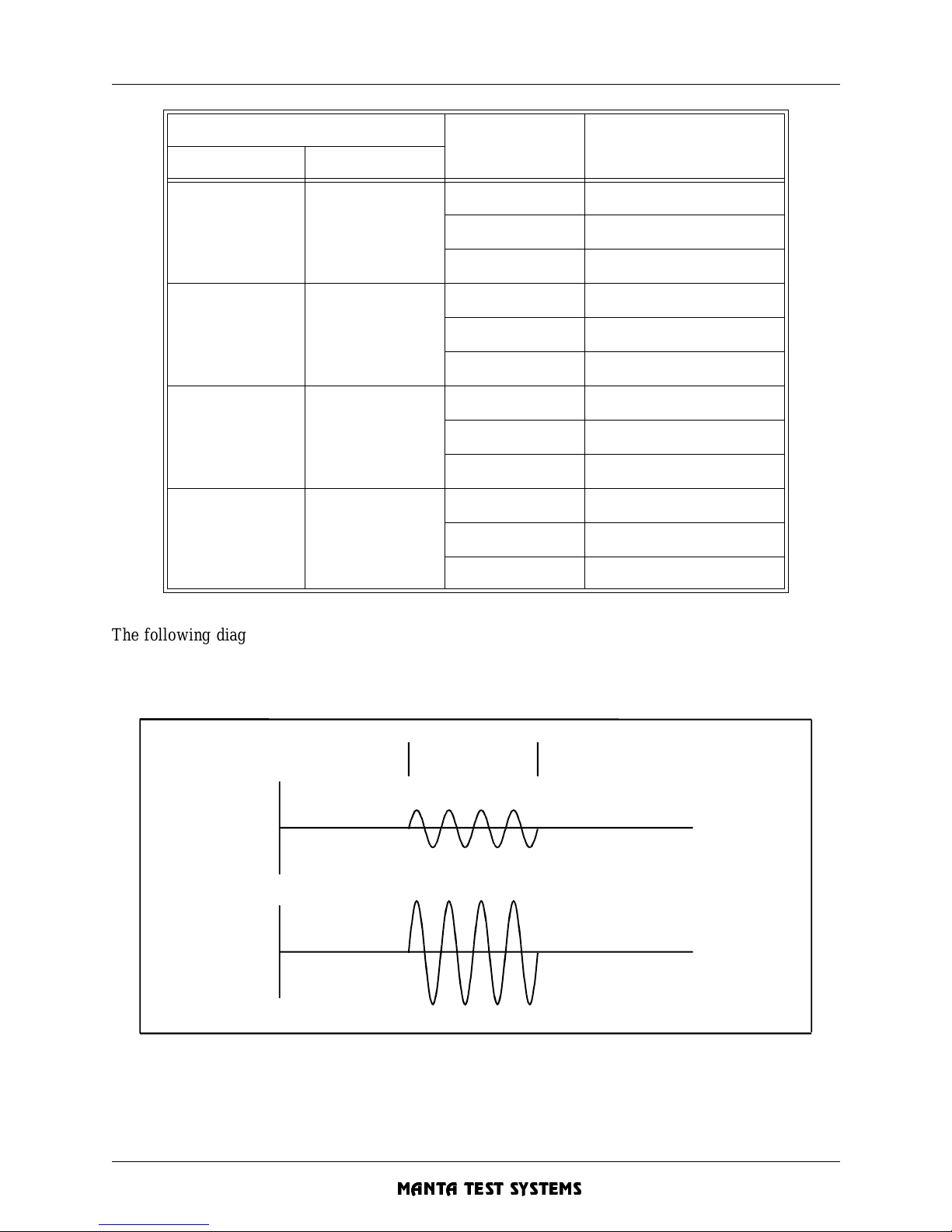
DETAILED OPERATION - Section 4
MTS-1700 SERIES OPERATION AND REFERENCE MANUAL 4-5
CU A002 15A
MANTA TEST SYSTEMS
The following diagrams depict some of the typical sequences which may be simulated. These examples
have a fault current significantly higher than the prefault, and a fault voltage significantly lower than the
prefault. The postfault current and voltage, if enabled, are the same as the prefau lt settings.
FIGURE 4.3 EXAMPLE OUTPUT SEQUENCE (PREFAULT OFF & POSTFAULT ON)
Selections
FAULT STATE OUTPUT LEVELS
PREFAULT POSTFAULT
OFF OFF
PREFAULT OFF
FAULT FAULT LEVEL
POSTFAULT OFF
ON OFF
PREFAULT PREFAULT LE V EL
FAULT FAULT LEVEL
POSTFAULT OFF
OFF ON
PREFAULT OFF
FAULT FAULT LEVEL
POSTFAULT POSTFAULT LEVEL
ON ON
PREFAULT PREFAULT LE V EL
FAULT FAULT LEVEL
POSTFAULT POSTFAULT LEVEL
I
V
P
OSTFAULTFAULTPREFAULT
Page 96
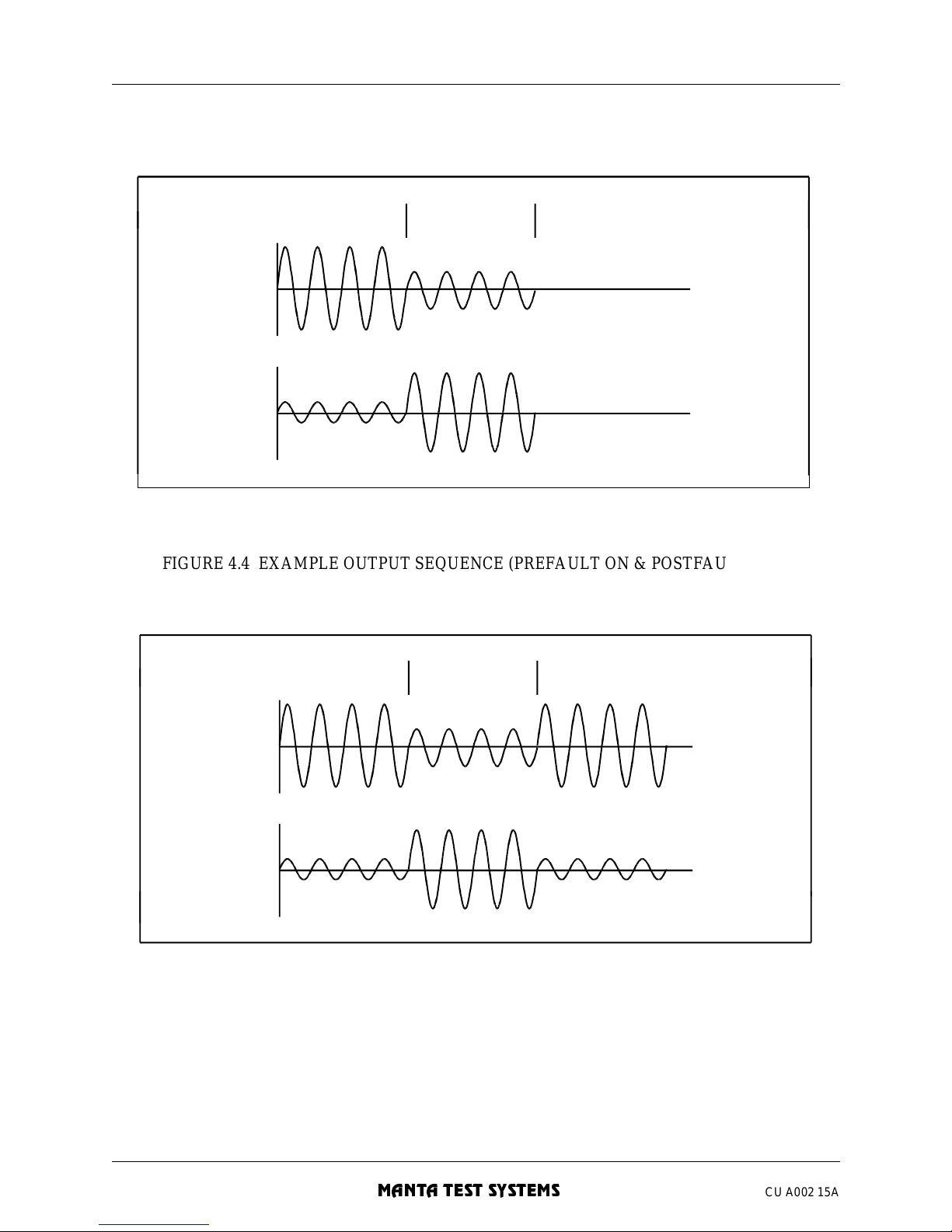
DETAILED OPERATION - Section 4
4-6 MTS-1700 SERIES OPERATION AND REFERENCE MANUAL
MANTA TEST SYSTEMS
CU A002 15A
FIGURE 4.4 EXAMPLE OUTPUT SEQUENCE (PREFAULT ON & POSTFAULT OFF)
FIGURE 4.5 EXAMPLE OUTPUT SEQUENCE (PREFAULT ON & POSTFAULT ON)
PREFAULT FAULT POSTFAULT
V
I
I
V
P
OSTFAULTF AULTPREF AULT
Page 97
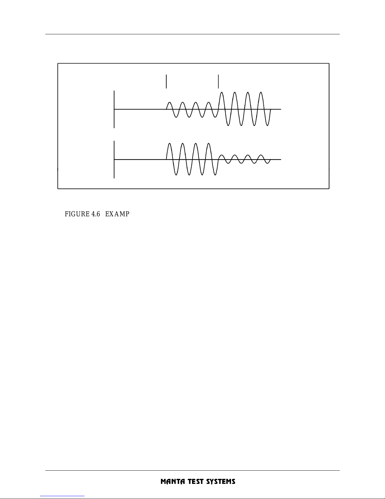
DETAILED OPERATION - Section 4
MTS-1700 SERIES OPERATION AND REFERENCE MANUAL 4-7
CU A002 15A
MANTA TEST SYSTEMS
FIGURE 4.6 EXAMPLE OUTPUT SEQUENCE (PREFAULT OFF & POSTFAULT ON)
4.5 TRIGGER/TIM ER OPERATION
Transition s between the t hree fault states a re caused by exte rnal or internal t riggers. The th ree possible
trigger actions are START, STOP and RESET.
4.5.1 Start T rigger
A “start” trigge r causes the MTS-1710 to enter the FAULT state . This only occurs if the MTS-1710 was in
the PREFAULT state.
A start trigger may be cause d by pressing the [FAULT] button. The timer may be set to start synchronously
with this action, or to start when an externall y provided signal changes. These trigge rs are referre d to as the
“internal star t” and “exte rnal start” timing modes (see Section 5.3 for details).
4.5.2 Stop Tri gger
A “stop” trigger always cause s the system to ente r the POSTFAULT state. It may be caused by a voltage or
contact change on the [EXTERNAL STOP] trigger inputs.
The stop trigger ac tion is disabled in static opera tion mode. This eliminates the need to c onstantly reset the
system when doing tests (such as minimum pickup) which result in numerous STOP triggers.
In static operation mode, only the tone LED and tone (if enabled) turn on when a closed contact or voltage
is sensed on the [EXTERNAL STOP] trigger inputs.
PREF AULT F AULT POSTFAULT
V
I
Page 98
DETAILED OPERATION - Section 4
4-8 MTS-1700 SERIES OPERATION AND REFERENCE MANUAL
MANTA TEST SYSTEMS
CU A002 15A
4.5.3 Reset
A “reset” trigger always caus es the system to enter the PREFAULT state. It can only be caused by pressing
the [STOP/RESET] button.
4.5.4 External Start Trigger Inputs
These three input terminals allow external contacts or voltage signals to trigger the MTS-1710 into the
FAULT state.
The top and centre terminals detect voltage change-of-state. The lower and centre terminals detect contact
impedance change-of-state, such as contact closure or low-impedance voltage source appearance.
In either case, the changing of a signal causes a start trigger. This could be the disappearance of a signal,
thus enabling trigger action from contact opening/voltage disappearance, as well as the more conventional
contact closure/ voltage appearance.
The recommended mode is to use voltage sensing whenever possible, since the voltage sensing terminals
don’t inject a voltage of their own into the circuit under test. The voltage output from the impedance
terminals, although of a very high source impedance (50k ohms), may be sufficient to alter observed
operation time of sensitive electronic relays.
Up to 300VDC may be applied to any one of the three terminals without damage. AC voltage should be
avoided due to the inherent poor accuracy caused by its continuous level variation.
Input impedance of either pair is greater than 50k ohms. Complete galvanic isolation up to 300VDC is
assured between these terminals and system ground, and all other inputs and outputs.
4.5.5 External Stop Trigger Inputs
These three input terminals allow external contacts or voltage signals to trigger the MTS-1710 into the
POSTFAULT state. They’re primarily used to sense relay operation.
The sensing action, impedance characteristics, and isolation of these inputs are the same as those of the
[EXTERNAL START] trigger inputs (see Section 4.5.4).
Page 99
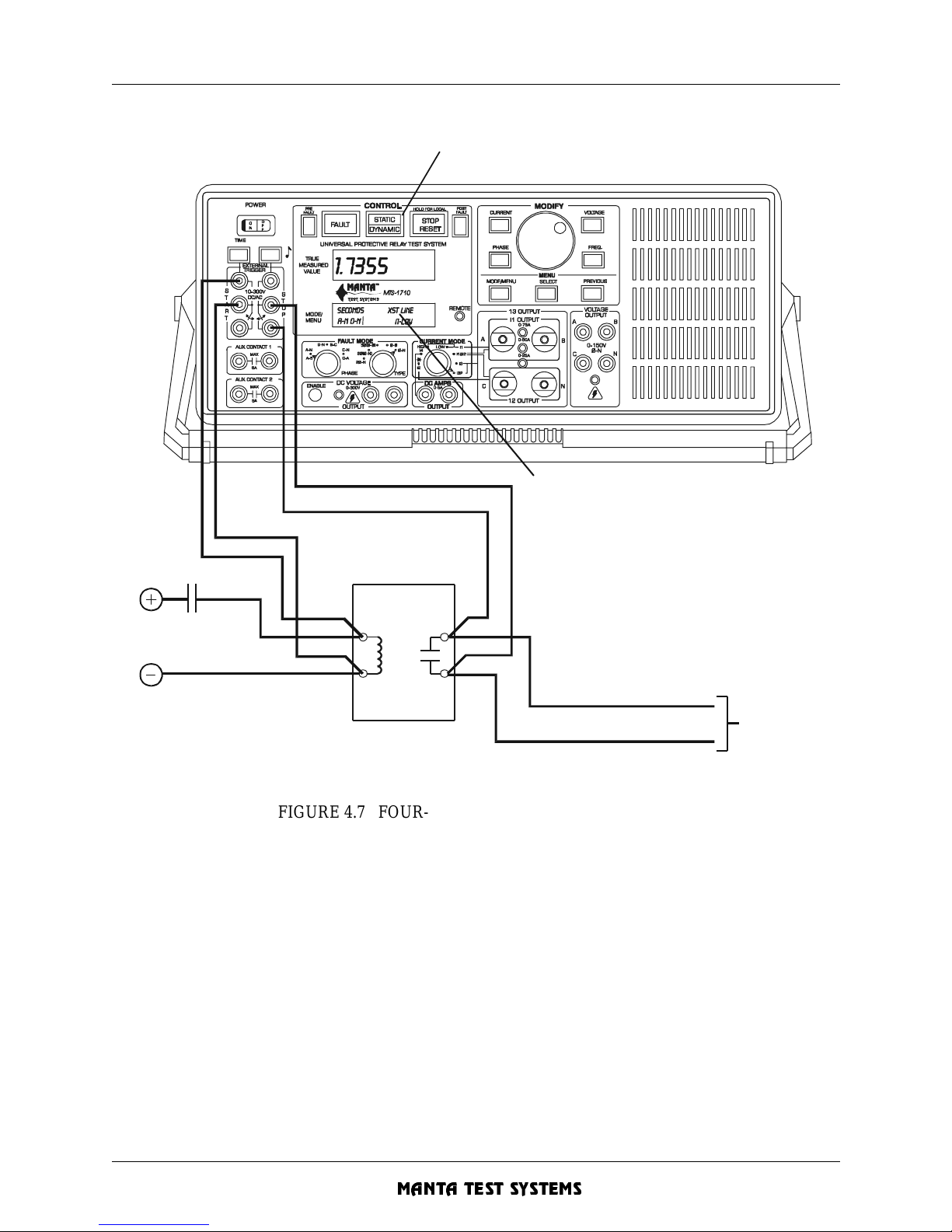
DETAILED OPERATION - Section 4
MTS-1700 SERIES OPERATION AND REFERENCE MANUAL 4-9
CU A002 15A
MANTA TEST SYSTEMS
FIGURE 4.7 FOUR-WIRE TIMING MEASUREMENT
4.5.6 Trigger Threshold Levels
The threshold volta ge level on the trig ger inputs is 10V. This low se tting was chosen to accommodate newer
solid state relays with low volta ge logic level outputs.
However, this low thresho ld level may c ause fal se triggering when working in very n oisy environments. The
threshold levels may be raised if required.
Please contact Manta Test Systems for details.
S
elect DYNAMIC mode to run timing test
Select external timer start
mode via menu.
Use of 4-wire timing
measurement to measure
the operate time of an
externally activated relay.
To trip
circuits
Page 100
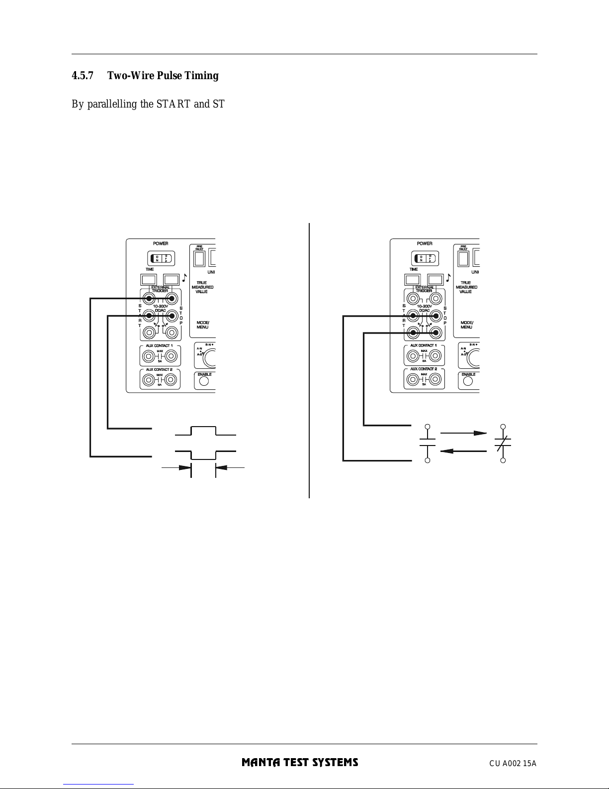
DETAILED OPERATION - Section 4
4-10 MTS-1700 SERIES OPERATION AND REFERENCE MANUAL
MANTA TEST SYSTEMS
CU A002 15A
4.5.7 Two-Wire Pulse Timing
By parallelling the START and STOP inputs, pulse type operations may be timed using only a single pair
of sensing leads.
The rising edge of a vol tage pulse, for example, would cause a star t trigger, and the falling edge would cause
a stop trigger. This allows measurement of the duration of a voltage pulse.
FIGURE 4.8 TWO-WIRE PULSE TIMING CONNECTIONS
4.5.8 Timing in Cycles
The [TIME] button toggles between tim ing in seconds and timing in cycles display.
Timing in cycle s is calc ulate d from the ti mer (s econds) re ading a nd the present freque ncy. In line f requency
mode, there must be a voltage output to obtain a frequency measurement, and subsequently a timing in
cycles value .
If the frequency changes during a test, the time in cycles value will assume that the frequency has always
stayed at the latest value (time in cycles doesn’t actually count power cycles--it’s a calculated value).
VOLTAGE PULSE INPUT
OR
C
ONTACT OPEN-C LOSE-OPEN
O
R CLOSE-OPEN-CLOSE INPUT
Time
PARALLELED START & STOP INPUTS FOR T W O-WIRE TIMING
V
Select EXTE R NAL START timing mode
via the front panel menu.
NOTE:
 Loading...