

Manson Engineering Industrial SBC-9138, SBC-9238 User Manual
SBC-9138/9238
Multi- Stage Smart Battery Chargers
User Manual
Keep this manual in a safe place for quick reference at all times.
This manual contains important safety and operation instructions for correct use of the battery charger. Read through the
manual and pay special attention to the markings and labels of the charger, battery and equipment connected to the
battery system.
Pay special attention to these two types of notices used in this manual.
WARNING:
Failure to heed this warning may cause injury to persons and damage to Equipment.
CAUTION:
Failure to observe this warning may result in damage to equipment and improper functioning of the Charger.
WARNING:
● The charger is designed for in-door use. Protect the charger from ingress of water.
● This charger is made to charge only properly sized lead acid batteries.
● Don't recharging non-rechargeable batteries.
● Charging other types of battery or under-sized lead acid batteries may cause fire or explosion.
● Install the charger in accordance with all local codes
● Do not use the charger if it has been dropped or damaged.
● Do not remove casing of the charger, there is no user-serviceable parts inside.
● Do not charge the battery on boats. Remove the battery and charge on shore.
● Never attempt to charge a frozen battery
● Never attempt to charge a damaged battery.
● Wear protective goggles and turn your face away when connecting or disconnecting the battery.
● Never place the charger on top of a battery.
● Never smoke, use an open flame, or create sparks near battery or charger during normal charging operation as
batteries may give out explosive gas.
● Do not charge batteries in an enclosure (box- in) due to possible explosion of entrapped explosive gas.
● Use of accessory not recommended may cause risk of fire, electric shock.
● Disconnect the mains supply before connecting or disconnecting the links to the battery.
● If the charger does not work properly or if it has been damaged, unplug its AC and DC connection.
CAUTIONS:
● Refer to battery manufacturer’s specific recommended values for battery type settings and float voltage setting.
● Fix the charger to a solid support via three grooves at the flange of chassis, with three screws or nuts.
● Ensure all ventilation ports are not obstructed for efficient fan cooling, keep loose soft material or paper off at the vent
holes of the charger.
● During charging, the battery must be placed in a well ventilated area.
● If longer output charging cord is required, make sure the diameter is adequate for the current in given cable length.

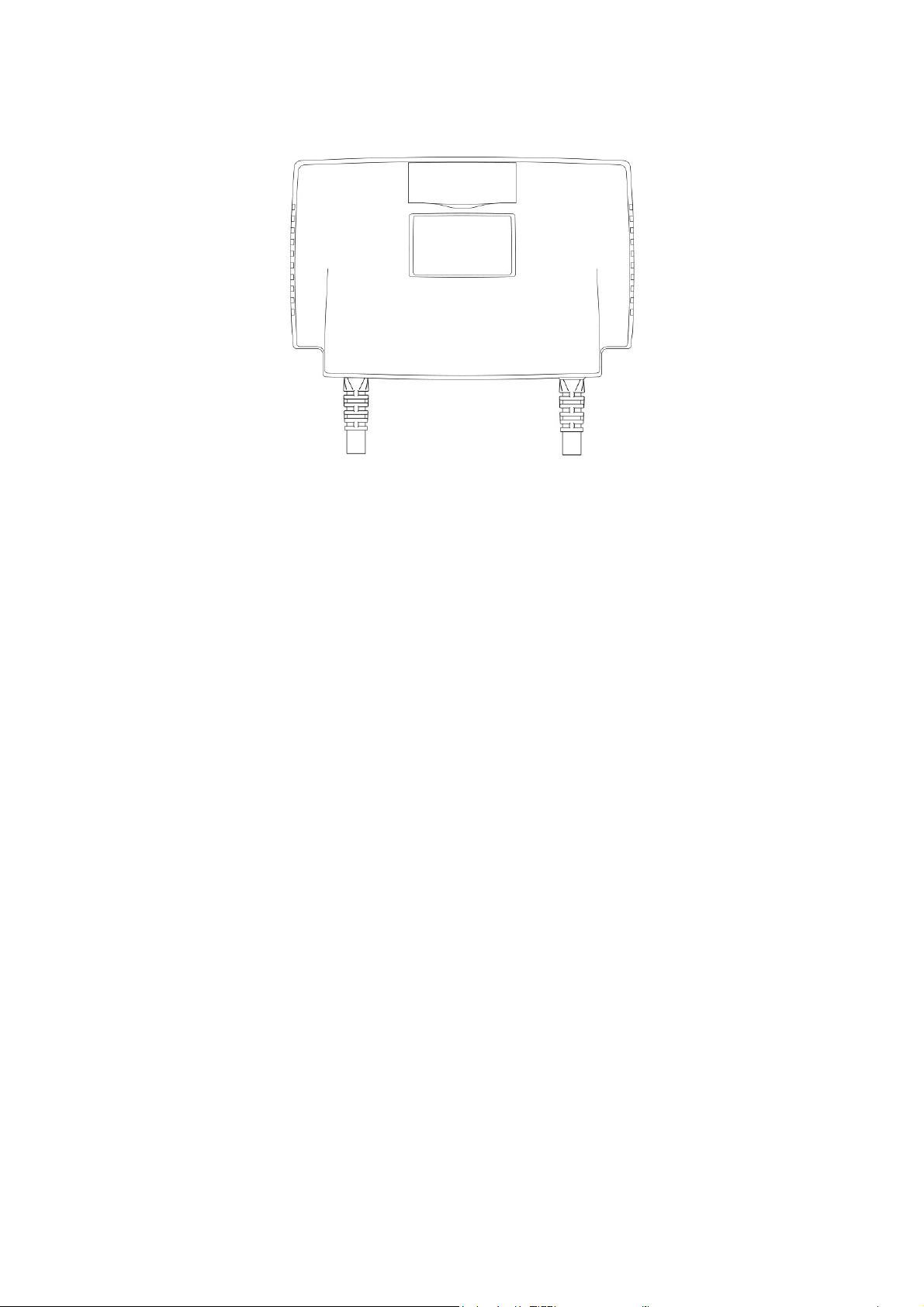
Fig.1
INTRODUCTION
Congratulations on purchasing our new Multi-Stage (IU0U) Switching Mode Smart Battery Charger.
This software based MCU control 7 stage smart charger is designed with user friendly features and software plus
hardware protection. It is a set, connect and forget charger that ensures complete recharge of your battery.
Your battery can be connected indefinitely to the charger which will enter into energy conservation mode to prevent over
charging and save electricity bills. The battery state of charge and temperature are closely monitored, updated and
logged by the MCU and the remote temperature sensor mounted on the supplied charger cable and heavy duty battery
clamps.
Though the charger basically is engineered to charge high capacity battery/ banks, it can be made to charge much
smaller battery by selecting the right reduced output setting. This charger can also be converted to a fixed voltage power
supply with one simple concealed which setting.
The extensive protection with alarm and LED indications including the thermostatic decrease of charging current to shut
down ensure a durable working life span even in harsh conditions for the charger and the battery. There are selections for
WET, AGM, GEL and Calcium-Calcium battery types. Special evaluation, conditioning charging profiles are made for the
WET type battery so to recover deeply discharged WET lead acid battery.
There is a Power Supply (PS) mode to provide a constant voltage DC power 13.3V to the external load connected to the
battery and at the same time without over charging the battery.
Almost all the protections are controlled by the Micro-Processor. On start up, the chargers run a series of self tests on the
protective functions, displays and critical components like the cooling fan.
Intended Use:
All Automotive, Marine, Mobile Home, Electric Scooters, Golf Carts, Solar, Deep Cycle, UPS Standby, Industrial &
Commercial Applications.
A. Control and Indicators
1. Charger status LCD display
Display the charging status, charging voltage/ current, battery type selected and etc.
Details please see this section below.
2. Programming Port
Factory use only
3. Recondition mode switch
Simple press and hold 3 seconds the switch to set the charger to go with recondition charge in next cycle.
4. Battery selection switch
For Wet, AGM, GEL, Calcium-Calcium and Power supply mode. (Default at position 3 the GEL type)
5. Charging current selection switch (Manual de-rating)
Current can be selected to 20%, 40%, 60%, 80% and 100% of the max current. Details please see the label
under the moveable door. (Default at 100%)
6. Back Light ON/OFF switch (Only for SBC-9138/9238)
Toggle ON/OFF the backlight by pushing the removable door, no need to open the door.
Press x 1 : Backlight ON for 5 minutes
Press x 2 : Backlight always ON
Press x 3 : To turn backlight OFF
7. Charging cable with removable temperature sensor
RED battery clamp– Battery positive pole
BLACK battery clamp– Battery negative pole
8. Removable temperature sensor
To increase/ decrease charging voltage at low/ high battery temperature
9. Ventilation Fan
Thermostatic control fan from zero to full speed
10. AC input power cord
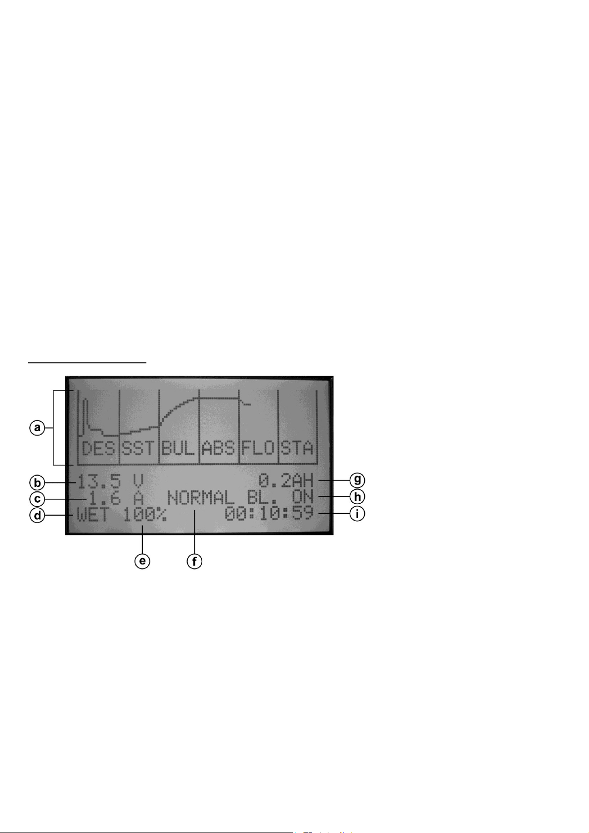
LCD Display Indication
a. Charging status curve
To show the battery charging status
DES: Desulphation charge (charging with pulse charge)
SST: Soft start (charging with 1/2 the max current)
BUL: Bulk charge (charging with constant max. current)
ABS: Absorption (charging with preset constant voltage)
REC: Recondition charge (for WET battery type only)
FLO: Float charge (charging with preset constant voltage)
STA: Standby (charging with 96% of the preset constant float voltage)
b. Voltmeter
Displays the charging voltage
c. Ammeter
Displays the charging current
d. Battery type
Displays the battery type selected
e. Power level meter
Charger Model
SBC-9138 , 12V/25A
SBC-9238 , 24V/13A
Battery Capacity
20 AH - 250 AH
10 AH - 125 AH
Displays current power level (the % of output current selected, details please see section F)
f. Charging status
NORMAL: Charging with normal profile
RECOND: Charging with Recondition mode
g. AH meter
Displays total AH value for the charging
h. Backlight status
To show the backlight status
BL. ON: Backlight always ON
BL. T: Backlight will ON for 5 minutes
BL. OFF: Backlight OFF
i. Run timer
Displays unit total run-time
B. Battery Type Selection
Make sure the charger is power OFF, use a small slot type screw driver to select the battery through Battery Selection
Switch (4). Please refer to the label under the removable door for battery type selection list
The LCD will display the battery type you selected after restart the charger.
WET : Flooded Type lead acid batteries (to which water can be added) Automotive or Deep Cycle
AGM/GEL : Sealed type (VRLA), AGM-GEL, Maintenance Free, Automotive or Deep Cycle lead acid batteries
Calcium-Calcium : Sealed type (VRLA) Lead Acid batteries with Calcium content Automotive or Deep Cycle
Power Supply : to provide a constant voltage DC power 13.3V to the external load connected to the battery and at
the same time without over charging the battery
B1. Recommended Battery Capacity
The following minimum AH capacities are a generalized suggestion, some batteries can take higher charge current,
check with battery manufacturers for charging batteries with smaller capacity.
C. Battery Charger Installation and Connection
Observe the warnings & safety precautions before rushing to install and operate the charger.
Check battery condition, fill up cells for wet battery, clean battery poles.
Secure the battery charger in a well ventilated place, make sure the mounting surface is flat and without soft covering
material or loose paper sheet. The air intake is at the left side and air outlet at the right side. Make sure both intake and
outlet are not blocked. Never place charger on top of battery.
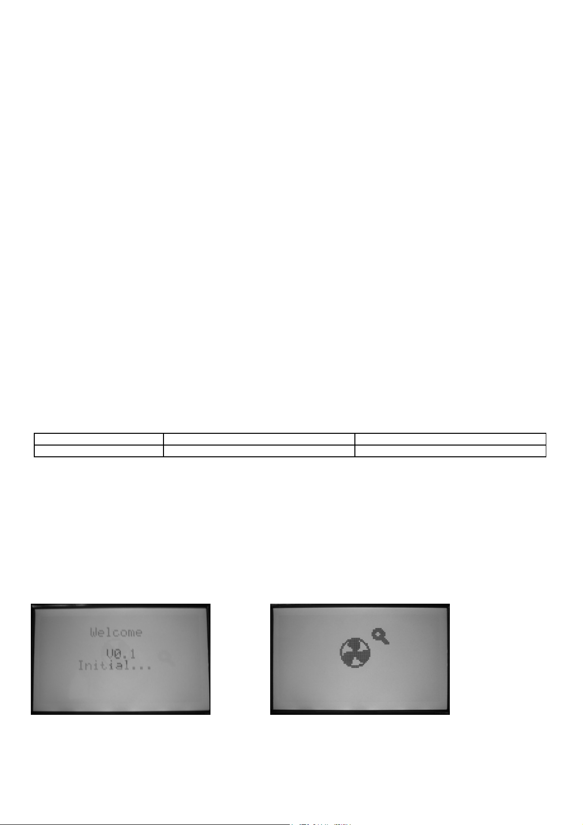
Plug in the AC mains. The LCD will display “Welcome” and unit software version and then go through a self-test.
The cooling fan spins at full speed for 3 seconds and a “Beep” sound by means of Self-Testing.
Figure to show charger initial Figure to show internal DC fan is under checking
 Loading...