

Page 1
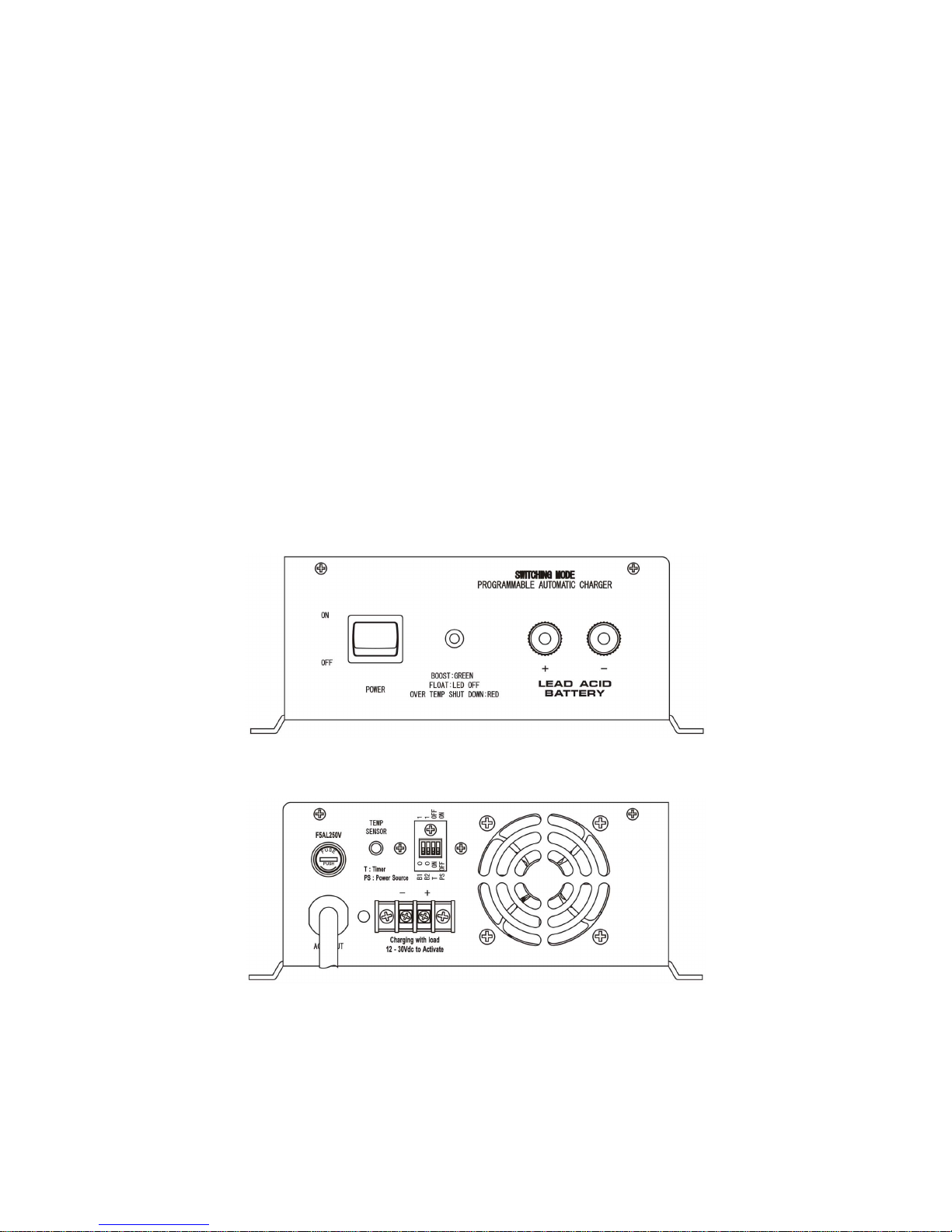
SWITCHING MODE
PROGRAMMABLE
AUTOMATIC CHARGER
for
Lead-Acid Battery
SBC-Series
User's Manual
7673-8112-0000
Page 2

SBC-Series Switching Mode Programmable Automatic Charger User Manual
1. INTRODUCTION
This series of battery chargers are field proven for charging all types of lead acid batteries including Gel and
AGM. They are ideal for caravan, motor homes. Wheelchair, electric scooter and etc.
Main Features are:
(a) Charging battery with external load connected at the same time.
(b) Lead acid wet/gel cell selector switch for optimum Boost and Float Charge Voltages based on
battery type.
(c) Fully Automatic, battery can be left on charge unattended all the time.
(d) Temperature compensation adjusts charging voltage based on battery temperature via remote
(optional accessory).
2. SAFETY PRECAUTIONS
1. Do not smoke, strike a match, place metal tools on battery or cause a spark in the vicinity of the
battery. When removing battery cables, remove ground cable first.
2. Do not charge the battery on boats. Remove the battery and charge on shore.
3. Lead Acid Battery contains highly corrosive sulphuric acid. Avoid contact with eyes, skin and
clothing while working with battery.
4. Working in Vicinity of a Lead Acid Battery is dangerous. Batteries generate EXPLOSIVE gases
during normal operation. Provide ventilation to outdoors from the highest point of the battery
compartment.
5. Be extra cautious to reduce the possibility of dropping a metal tool onto batteries. It might spark or
short circuit batteries or other electrical parts that may cause explosion. Cover wrench handles
with plastic tape or vinyl dip coating material.
6. Do not expose charger to rain, snow and wet conditions.
7. Use charger only for Lead-Acid Batteries.
8. Check that the model number of the charger matches the voltage and capacity of the battery.
Model no. Battery Voltage Maximum Charging Current Recommended Battery Capacity
SBC-8112 12V 10A 50-120 AH
SBC-8125 12V 20A 120-200 AH
SBC-8215 24V 10A 50-120 AH
( Table 1 )
9. Please refer to battery manufacturer’s specific recommended values for setting Boost(Bulk)
charging voltage.
10. Before using the battery charger, read all the instructions and cautionary markings on the battery
charger and the batteries
11. Do not attempt to repair the battery charger. Incorrect re-assembly may result in a risk of electric
shock or fire.
12. To reduce risk of electric shock, disconnect all wiring before attempting any maintenance or
cleaning Turning off controls will not reduce this risk.
P.1
Page 3
SBC-Series Switching Mode Programmable Automatic Charger User Manual
3. CONTROL AND INDICATORS
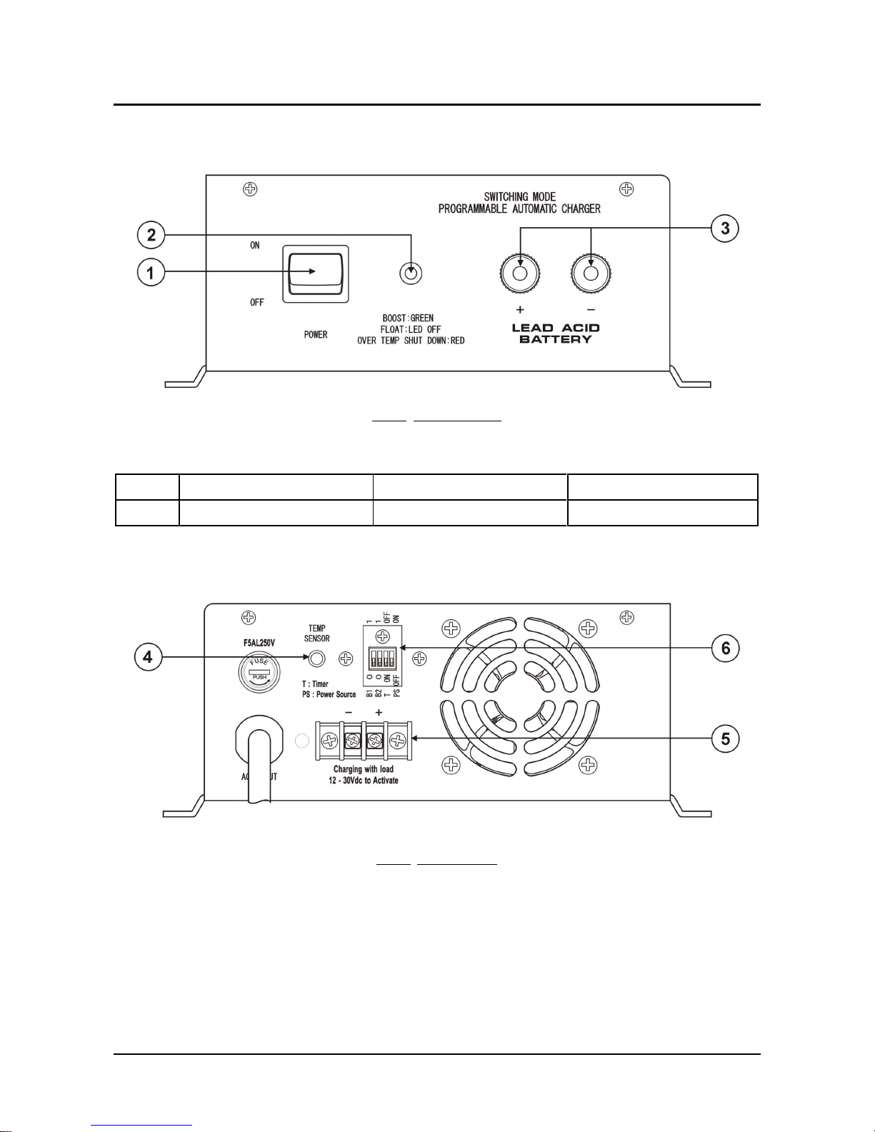
FIG.1 FRONT VIEW
1. Power ON/OFF Button, power on with light
2. LED INDICATOR
Color
Green Red LED Off
Status
Boost Charge Mode Over-temperature Shutdown Float Charge mode
( TABLE 2 )
3. OUTPUT TERMINAL (CONNECTED TO LEAD ACID BATTERY)
FIG.2
BACK VIEW
4. Temperature Sensor Terminal
5. Remote Control Terminal (12-30VDC Input) (Section 4.1 C)
6. Dip Switch Control
P.2
Page 4
SBC-Series Switching Mode Programmable Automatic Charger User Manual
4. OPERATIONS
4.1 Charging Methods
There are 3 charging methods.
A. Normal Charging
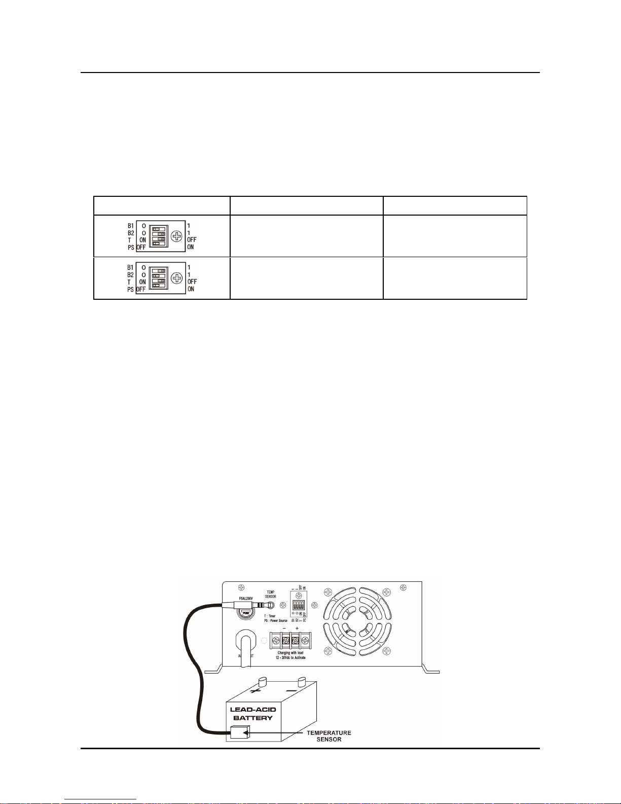
1. Check and set the Dip Switch Control Settings for your battery type: Wet, Seal or AGM Type.
Then set the set the timer T to Off and PS to Off ( Table 3 ).
2. Put the ring/spade connector of your cable to the terminal pole first, then the spring washer and
screw as tight as possible.
3. Recheck the tightness by jigging the cable and ensuring the spring washers are flat.
4. Switch on the charger and the LED should light up in green. The charger will Boost Charge the
battery until fully charged up then the charger will switch to Float voltage automatically and the
LED will be Off.
The Charger can be left unattended without worrying about overcharging the battery. In case,
the battery becomes low again, the charger will automatically start the Boost to Float charging
cycle again.
5. To use the Temperature Compensation Function, plug a PT100 Temperature Sensor (optional
accessory) into the Temperature Sensor Terminal and attach it firmly on the side of the battery
( FIG. 3 ).
For 12V system( SBC-8112, 8125 ), it will regulate at -20mV/degree C increase.
For 24V system( SBC-8215 ), it will regulate at -40mV/degree C increase.
When the battery's temperature is about 60 degree C, the LED will be red and the charger will
stop charging the battery. Turn off the charger to reset the charger.
( FIG. 3 )
P.3
SBC - 8112 / 8125 ( 12V system ) SBC - 8215 ( 24V system )
13.9V 27.8V
14.4V 28.8V
Table 3
Page 5
SBC-Series Switching Mode Programmable Automatic Charger User Manual
B. Timer Charging
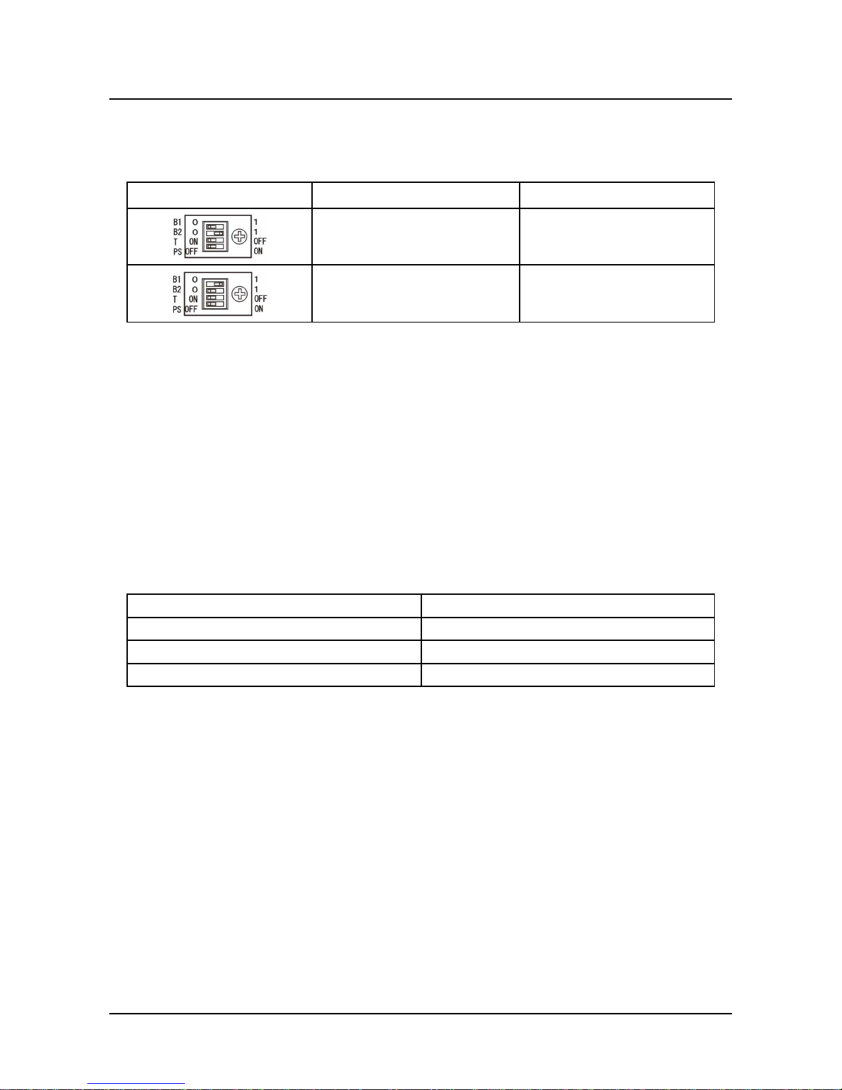
1. After checking for the correct battery type on B1 and B2 Dip Switch, set the timer T to On and
PS to Off ( Table 4 ).
2. Switch on the charger, it will Boost Charge the battery for 4 hours only, then to Float Voltage
automatically
3. It will not go back to Boost Voltage again.
4. Switch the charger Off and On to start another 4 hours timer charging.
5. To use the Temperature Compensation Function, please refer to section A step 5.
6. The temperature cut off over-ride the timer preset when temperature sensor is used.
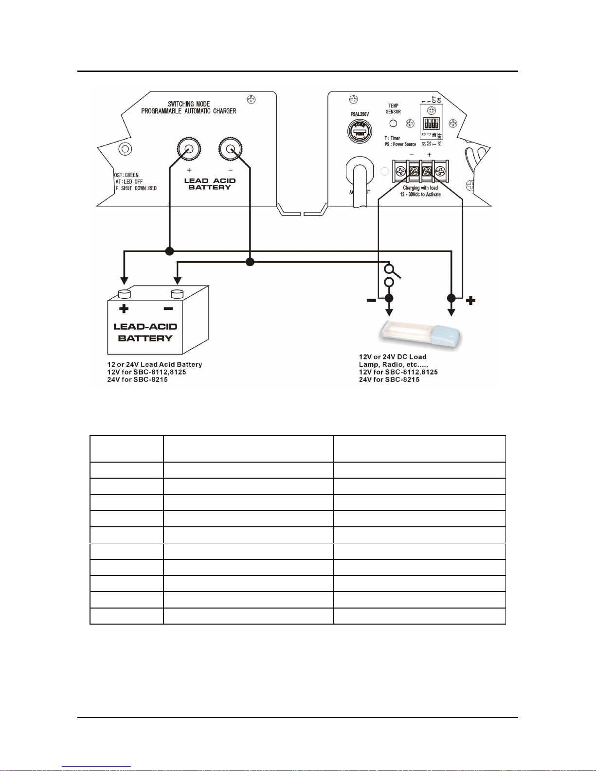
C. Charging battery with external load connected ( Ideal for Caravan and motor homes
application )
In this mode, the charger will carry external loads and still keep the battery in a full charge
condition without overcharging the battery. When the load is On, the charger will only deliver a
semi-boost voltage to the battery( 13.4V for 12V system, 26.8V for 24V system ).
When the external load is off, the charger will resume its normal Boost to Float cycle automatically.
Long term continuous loads should be limited to 50% of the charger rated output.
1. Connect the wiring diagram for external load as shown in ( Fig.4 ) with proper selection of cable
size and ON/OFF switch taking into account of voltage drop due to the length of cable ( Table
6 ). Make sure the cable from from the charger to battery as short as possible and the battery is
installed in a well ventilated location.
P.4
SBC - 8112 / 8125 ( 12V system ) SBC - 8215 ( 24V system )
13.9V 27.8V
14.4V 28.8V
Table 4
Model No. Continuous Rating of the Load
SBC-8112 5 A
SBC-8125 10 A
SBC-8215 5 A
Table 5
Page 6
SBC-Series Switching Mode Programmable Automatic Charger User Manual
P.5
Wire Size
(AWG)
Max. one-way distance ( feet )
for 2% voltage loss (10A)
Max. one-way distance ( feet )
for 2% voltage loss (20A)
14 4.5 2
12 7 3.5
10 11.5 5.5
818 9
6 28.5 14.5
4 45.5 22.5
2 72.5 36
1/0 115 57.5
2/0 145 72.5
4/0 230 116
Table 6 Selection of cable size and length vs current
( Fig.4 Setup for charging with external load )
Page 7
SBC-Series Switching Mode Programmable Automatic Charger User Manual
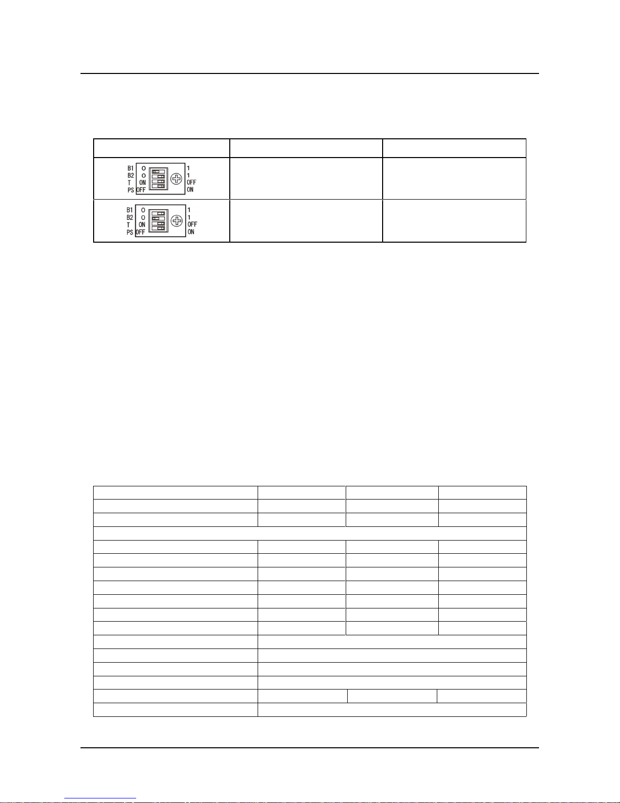
2. Adjust the Dip Switch B1 and B2 to select the correct Boost Charge Voltage.
3. After checking for the correct battery type on B1 and B2 Dip Switch, set the Dip Switch T to Off
and the PS to ON state ( Table 7 ).
4. Turn On the charger and turn Off the external load On/Off switch, measure the battery terminal
voltage to check for correct Boost Charge Voltage for battery type used.
5. To use the Temperature Compensation Function, please refer to section A step 5.
WARNING: Use an ON/OFF Switch with appropriate RATING for the load in setup of ( Fig.4 ).
REMARKS:
There are situations that the voltage drop due to the workable cable size and the battery
location cause the Boost Charge Voltage at the battery terminals below the recommended
value. Then depending on the value of the de-rated Boost Voltage, change to a Gel Type of
Battery or consult your dealer for a higher voltage type charger on request .
(Note: factory preset 14.8/15.5V for 12V System or 29.6/31.0V for 24V System).
The Temperature Sensor(optional accessory) protects the battery from overheating due to
environment or faulty cell or low water level. When the temperature of the battery reaches
around 60 degree C, the over-temperature shutdown will be triggered and the charger will be
shut down completely to avoid damages to the battery and the charger.
P.6
SBC - 8112 / 8125 ( 12V system ) SBC - 8215 ( 24V system )
13.9V 27.8V
14.4V 28.8V
Table 7
5. SPECIFICATIONS
Model SBC-8112 SBC-8125 SBC-8215
Batter
y Sy
stem
12V 12V 24V
Recommended Batter
y
Capacit
y
50-120 AH 120-200 AH 50-120 AH
Out
p
ut (@25ºC
)
Max. Charging Current
10A 20A 10A
Float Mode Char
ging
Voltage
13.3V 13.3V 26.6V
Semi-Boost Mode Char
ging
Voltage
13.4V 13.4V 26.8V
Boost Mode Char
ging
Voltage
13.9/14.4V 13.9/14.4V 27.8/28.8V
Line Re
g
ulation(+/- 10%)
80mV 100mV 80mV
Load Re
g
ulation (0-100% Load
)
< 150mV < 200mV < 200mV
Ri
pp
le and Noise (V
r.m.s.
)
< 25mVrms < 25mVrms < 35mVrms
Efficienc
y
80%
In
p
ut Voltage
230VAC / 50Hz
(
or 120VAC / 60Hz on request
)
Cooling System
Current Controlled Fan
Dimensions
( L)
255 x (W) 200 x (H) 80 mm
Wei
g
ht
2k
g
3.5k
g
3.5k
g
Approvals
Desi
g
ned and manufactured to comply with CE
 Loading...