

Manson Engineering Industrial SBC-6108, SBC-6112, SBC-6120 User Manual
PV Charge Controller
SBC-6108 / 6112 / 6120
User's Manual
Table of Contents
Precautions and Specifications 1
1. Introduction 2
2. Control and Indicator
2
3. Installation and Indication 3
3.1 Connection
3
3.2 LED Indicator 3
3.3 Charging LED Indicator 4
3.4 The Dip Switch
4
3.4.1 Bulk Charge Voltage Setting for Sealed and Wet-type Lead Acid Battery
4
3.4.2 Select the Auto-Equalization charging and Night-Light Mode 4
4. PV Charge Control Mode 5
4.1 3-Stage Charge Control 5
4.2 Equalization Charging Mode (Automatic or Manual) 6
4.2.1 Automatic Equalization Charging 6
4.2.2 Manual Equalization Charging 6
4.3 12V DC Load Terminal- Control Mode 6
4.3.1 Low Voltage Disconnect (LVD) 6
4.3.2 Low Voltage Reconnect (LVR) 6
4.3.3 Night-Light Mode Programs 6
4.4 Temperature Sensor (Optional) 8
4.5 Over Temperature Protection
8
5. Remote Signal Terminal (Optional)
8
Precautions
1. Before using the charge/load controller, read all the instructions and cautionary markings on the
charge/load controller, the batteries and the photovoltaic panels.
2. Do not attempt to repair the controller. Incorrect re-assembly may result in a risk of electric shock or
fire.
3. To reduce risk of electric shock, disconnect all wiring before attempting any maintenance or cleaning.
Turning off controls will not reduce this risk. PV panels produce power when exposed to light – cover
them with opaque material before servicing.
4. Working in Vicinity of a Lead Acid Battery is dangerous. Batteries generate EXPLOSIVE gases during
normal operation. Provide ventilation to outdoors from the highest point of the battery compartment.
5. This charge/load controller is intended to be used with a battery supply of 12 VDC nominal voltage.
6. Be extra cautious to reduce the possibility of dropping a metal tool onto batteries. It might spark or
short-circuit batteries or other electrical parts that may cause explosion. Cover wrench handles with
plastic tape or vinyl dip coating material.
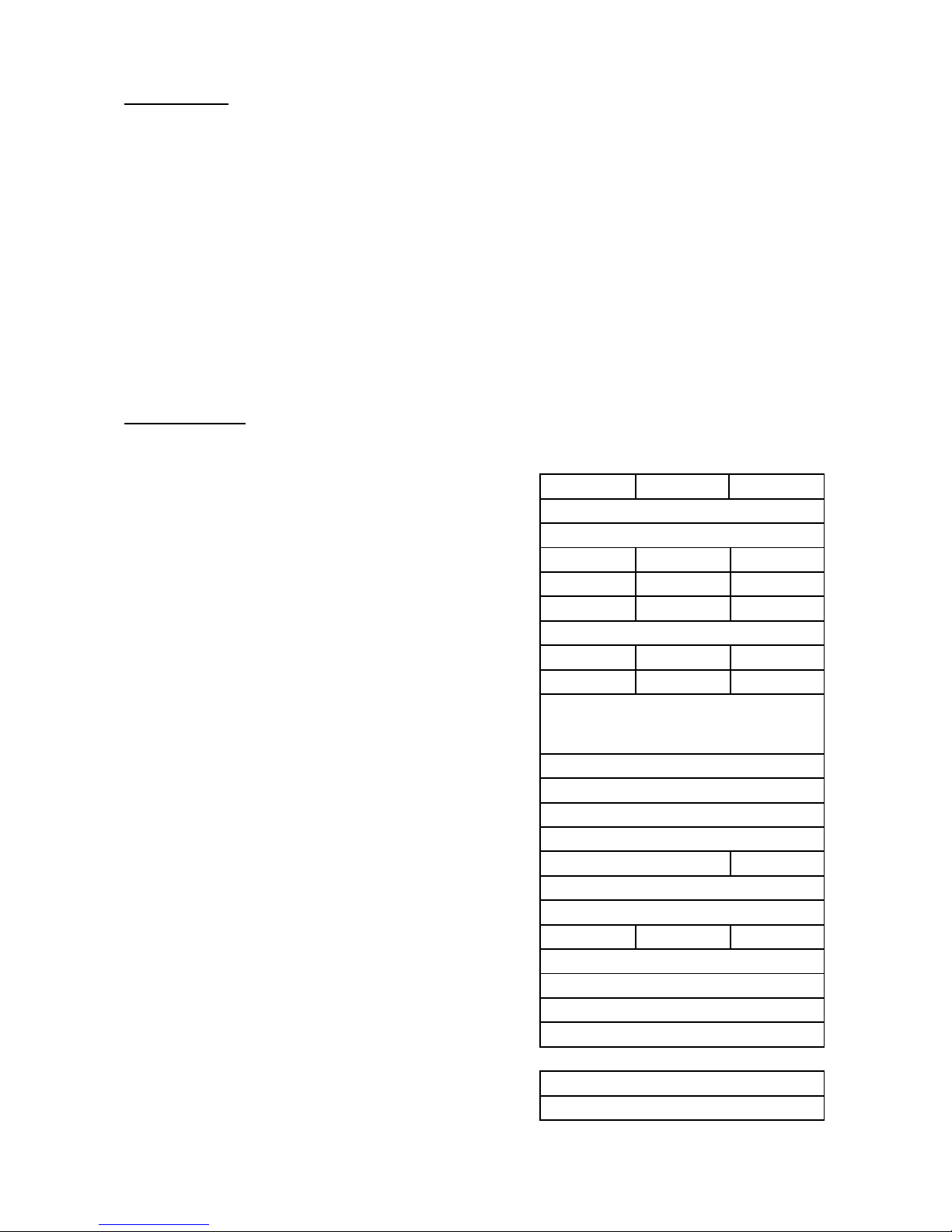
Specifications
SBC-6100 Series
Models
6108 6112 6120
Battery voltage
12V
Maximum PV panel open circuit voltage
26V
Continuous load/charge current
8A 12A 20A
Maximum charge current (5 mins)
10A 15A 25A
Maximum load current (5 mins)
10A 20A 25A
Operation current(no Load and no PV)
30mA
Voltage across terminals (PV to Battery)
0.6V 0.6V 0.8V
Voltage across terminals (Battery to Load)
0.3V 0.3V 0.4V
Electronic Blocking
(To protect against reverse polarity connection of PV panel and to block
current from battery to PV panel when voltage of battery is higher than PV
panel)
Yes
Battery reverse polarity protection
Yes
Overcharge & Over-discharge protection
Yes
Battery status LED indication
5-State LED Indications
Charging status indication
3-State LED Indications
Recommended wire size
#12AWG #10AWG
Weight
0.44 kg
Dimension (WxDxH)
150 x 85 x 45 mm
Fuse
15A 20A 30A
Operating ambient temperature
-10 to 50 °C
Over temperature protection
Yes
Battery charging float voltage setting
Factory Preset 13.5V
Battery charging bulk voltage setting
Factory Preset 14.3V
DC load control mode (For DC load terminal):
Low Voltage Disconnect(LVD)
Factory Preset 11.5V
Low Voltage Reconnect(LVR)
Factory Preset 12.5V
P.1
1. Introduction
The SBC-6108/6112/6120 PV Charge Controller is designed for use with all types of 12V
photovoltaic(PV) panels/systems and different types of 12V batteries, such as wet or sealed lead
acid, lead calcium, lead antimony battery.
Numerous features are provided to maximize the performance of the system:
● Electronic Blocking (To protect against reverse polarity connection of PV panel and block
current from battery to PV Panel when voltage of Battery is higher than PV panel),
● Suitable for PV panels with Open Circuit Voltage from 17 to 23V,
● Rated charging/load current 8A (SBC-6108)/ 12A(SBC-6112) / 20A(SBC-6120),
● PWM Charging,
● Build-In Microprocessor for PV charge control to maximize the charging efficiency,
● Overcharge and Over-discharge Protection,
● 3-stage Charge Control(Bulk, Absorption & Float) to allow battery be left unattended for long
period ,
● Over Temperature Protection,
● Night Light Mode 10 selections
● Short-Circuit Protection at load terminal & Battery Reverse Polarity Protection at Battery
Connection Terminal,
● Tri-Color LED indication of system and battery conditions,
● Optional Temperature Sensor for compensated battery charging,
● Optional Remote Signal Terminal.
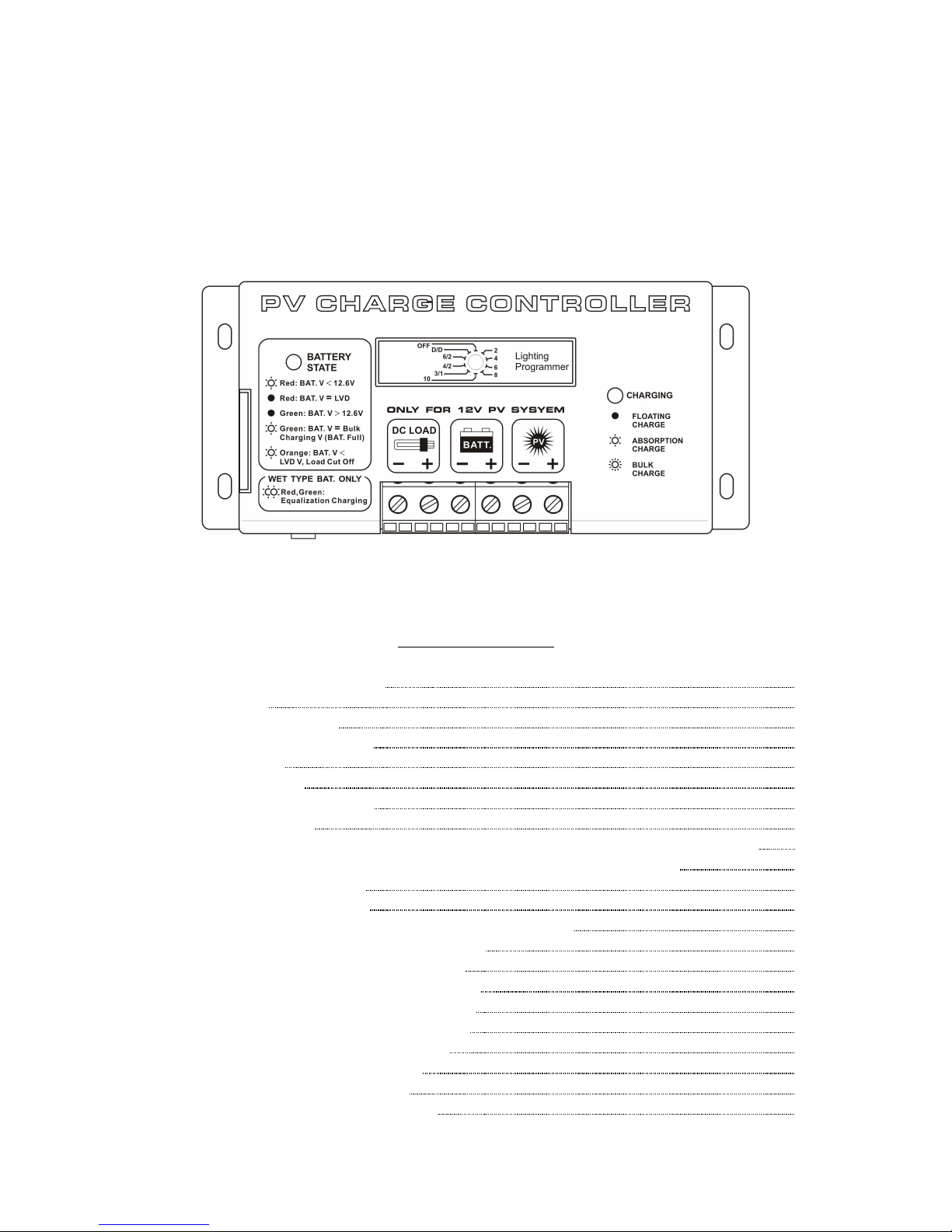
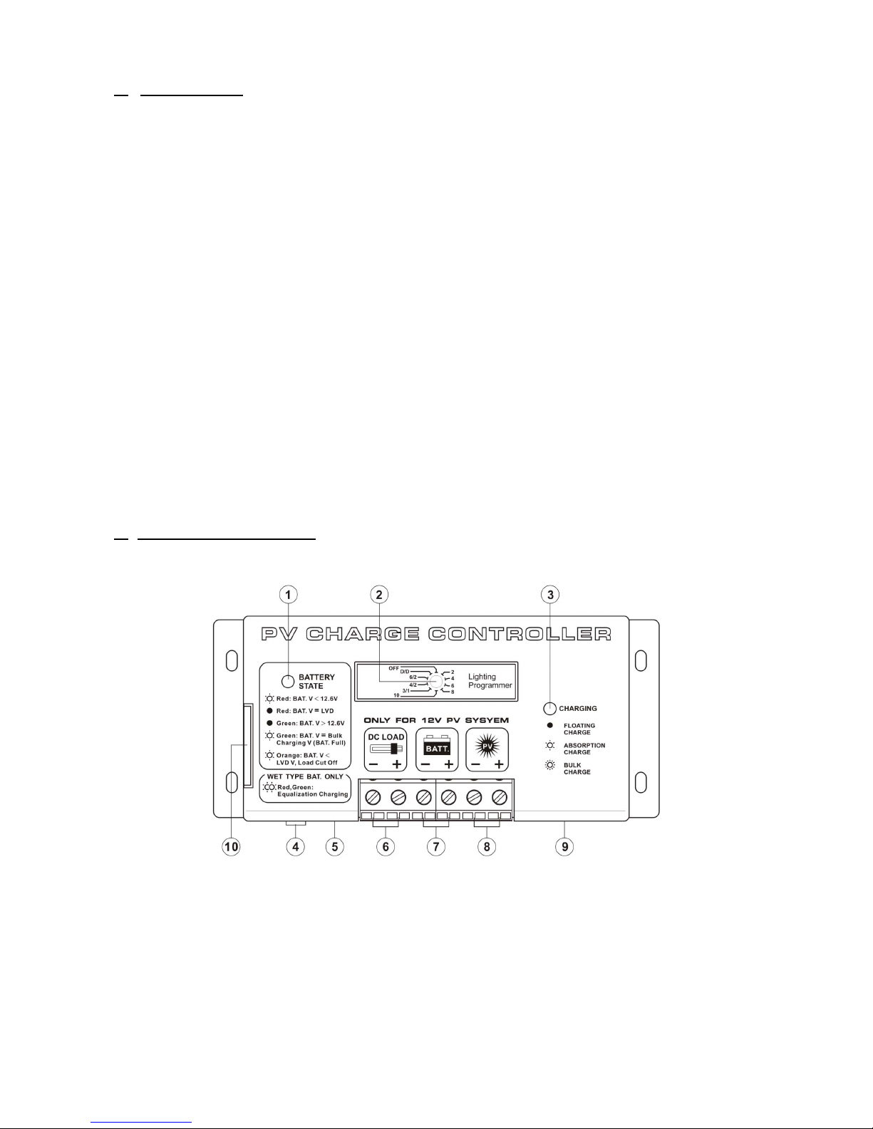
2. Control and Indicator
The following diagram shows the hardware interface of the PV Charge Controller.
Figure. 1 Front view of PV Charge Controller
1. Battery LED Indicator
2. Lighting Programmer (Night-Light Mode Selections)
3. Charging LED Indicator
4. Reset button (see Section 3.4)
5. Temperature Sensor (Optional)
6. 12V DC Load terminal with Low Voltage Disconnect/NIGHT-LIGHT mode (Section 4.3)
7. 12V Battery connection terminal
8. PV Panel connection terminal
9. Remote Signal Terminal (Optional)
10. Side Door (open to access switches for setting)
P.2
 Loading...