

Manson Engineering Industrial SBC-2215, SBC-2220, SBC-2225, SBC-2130, SBC-2140 User Manual
...
SBC-2215 / 2220 / 2225
3 Stage Battery Charger
User Manual
Keep this manual in a safe place for quick reference at all times.
This manual contains important safety and operation instructions for correct use of the battery charger. Read through the manual and
pay special attention to the markings and labels of the charger, battery and equipment connected to the battery system.
Pay special attention to these two types of notices used in this manual.
WARNING :
Failure to heed this warning may cause injury to persons and damage to Equipment.
CAUTION :
Failure to observe this warning may result in damage to equipment and improper functioning of the Charger.
WARNING :
● The charger is designed for in-door use. Protect the charger from ingress of water.
● This charger is made to charge only properly sized lead acid batteries.
● Charging other types of battery or under-sized lead acid batteries may cause fire or explosion.
● Install the charger in accordance with all local codes
● Do not use the charger if it has been dropped or damaged.
● Do not remove casing of the charger, there is no user –serviceable parts inside.
● Do not charge the battery on boats. Remove the battery and charge on shore.
● Never attempt to charge a frozen battery
● Never attempt to charge a damaged battery.
● Wear protective goggles and turn your face away when connecting or disconnecting the battery.
● Never place the charger on top of a battery .
● Never smoke, use an open flame, or create sparks near battery or charger during normal charging operation as batteries may give
out explosive gas.
● Do not charge batteries in an enclosure (box- in) due to possible explosion of entrapped explosive gas.
● Use of accessory not recommended may cause risk of fire, electric shock.
● Disconnect the mains supply before connecting or disconnecting the links to the battery.
● If the charger does not work properly or if it has been damaged ,unplug its AC and DC connection.
CAUTIONS :
● Refer to battery manufacturer’s specific recommended values for battery type settings and float voltage setting.
● Fix the charger to a stable surface using the holes at the flange.
● Ensure all ventilation ports are not obstructed for efficient fan cooling, keep loose soft material or paper off at the bottom of the
charger.
● If longer output charging cord is required, make sure the diameter is adequate for the current in given cable length.
Introduction
Congratulations on purchasing our new 3-Stage (IU0U) Switching Mode Battery Charger.
This battery charger is suitable for wet, sealed (RVLA), calcium-calcium, Gel and AGM in both car (SLI) and deep cycle type of
lead acid battery.
It is a “set and forget” automatic charger which can be permanently connected to battery.
These models have dual charge banks for charging two batteries simultaneously.
The special selectable Power Supply Mode allows charging battery with external load.
Intended Use:
All Automotive, Marine, Mobile Home, Electric Scooters, Golf Carts, Solar, Deep Cycle, UPS Standby, Industrial & Commercial
Applications.
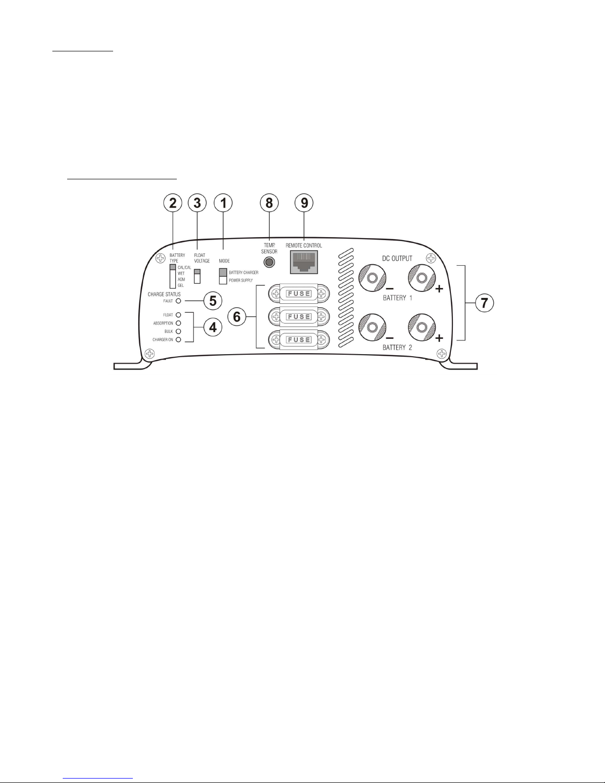
A. Control and Indicators
1. Battery Charger / Power Supply Selection
Slide Switch to set Charger to 3 Stage Charger or Power Supply Mode (See Section G)
2. Battery Type Selection
Slide Switch to set charger for AGM/Gel, Wet and Calcium-Calcium type battery.
3. Float Voltage Selection
Slide Switch to set Float Charge voltage to 26.4 / 27.0V / 27.6V.
4. Charge Status LED Display
Charger ON LED : Green - 3 Stage Charger Mode
Red - Power Supply Mode
BULK LED (Red ) : Bulk Charging with constant max. current
ABSORPTION LED (Orange) : Absorption charging with preset constant max. voltage.
FLOAT LED (Green) : Float charging with preset constant voltage
5. FAULT LED (Red)
Charger malfunction (See Trouble Shooting)
6. Car Blade Fuse
Fuse for reverse polarity protection .
7. Charging Banks
Screw Terminals to connect to supplied charging cable.
8. Temperature Sensor Socket
Connection to optional accessory ATS-5120
Sensor to increase / decrease charge voltage at low / high battery temperature .
9. Remote Control socket
Connection to optional accessory ABD-4120.
To remote display the charging voltage & charging status and remote control the charger output ON/OFF.
Fig.1
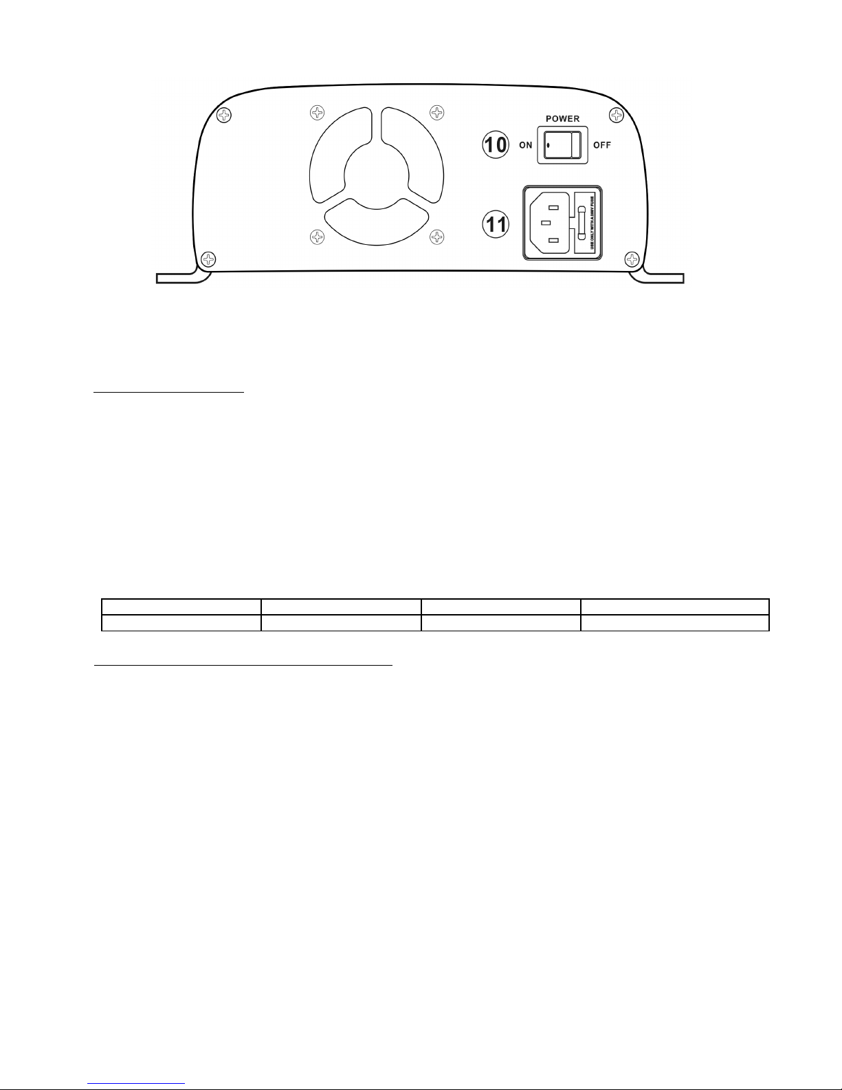
10. Power Switch
To turn on and off AC power to Charger.
11. Inlet AC Socket with Fuse Holder
B. Battery Type Selection
AGM/GEL : Sealed type (VRLA) , AGM-GEL , Maintenance Free , Automotive or Deep Cycle lead acid batteries
WET : Flooded Type lead acid batteries (to which water can be added) Automotive or Deep Cycle
Calcium-Calcium : Sealed type (VRLA) Lead Acid batteries with Calcium content Automotive or Deep Cycle
B1. FLOAT VOLTAGE SELECTION
These fine tuned selections of float voltages enable the best voltage level for maximum battery life. Choose 27.6V when in doubt
or in Power Supply Mode.
Follow the markings on Deep Cycle batteries of the Standby float voltage.
B2. Recommended Battery Capacity
The following minimum AH capacities are a generalized suggestion, some batteries can take higher charge current, check with
battery manufacturers for charging batteries with smaller capacity.
Charger Model SBC-2215 , 15A SBC-2220 , 20A SBC-2225 , 25A
Battery Capacity 50 AH - 150 AH 70 AH - 200 AH 80 AH - 250 AH
C. Battery Charger Installation and Connection
Observe the warnings & safety precautions before rushing to install and operate the charger.
Check battery condition, fill up cells for wet battery, clean battery poles.
Secure the battery charger in a well ventilated place, make sure the mounting surface is flat and without soft covering material or
loose paper sheet. The air intake is at the bottom and air outlet at the back. Make sure both intake and outlet are not blocked.
Never place charger on top of battery.
Plug in the AC mains and turn on Power Switch , the Charger On LED and the Float LED should be on green indicating Charger is
in good order for charging lead acid battery.
Before connecting or disconnecting the charging cable, turn off the Power Switch and unplug AC cord from the mains.
First connect the Red cable to Positive + terminal of charger and the battery Positive + Pole. Then connect the Black cable to the
Negative – terminal and the Negative – Pole of the battery.
Make sure all the connections are secured and well tighten up, double check on the correct polarity.
Double check again for correct selection of Slide Switch 1 at Charger Mode, Switch 2 for Battery type and Switch 3 for Float
Voltage setting value.
Fig.2
 Loading...