

Manson Engineering Industrial HCS-3300 USB, HCS-3302 USB, HCS-3304 USB, HCS-3600 USB, HCS-3604 USB User Manual
...
HCS-3300/3302/3304 USB
Remote Programmable Laboratory Grade Swi tching Mode Power Supply
User Manual
1. INTRODUCTION
Since the intro d uc tion of HCS ser ies power supplies i n 2 0 0 9, we ha ve mad e n u mer o us i mp ro vement within t he l i mits o f
the original hardware modules, firmware and software framework.
In the upgraded version of HCS series power supplies, both the hardware and the firmware have been modified, the
application software has a completely design in concert with the value added features.
Added features which can b e done on the u nit panel.
1. Reset no load current to zero on current meter.
2. Reset the 3 presets to factory default
2. WARNING
• Do not use this power supply near water.
• Do not operate or touch this power sup ply with wet hands.
• Do not open the casing of the power supply when it is connected to ac mains.
• Refer all servicing to qualified service personnel only.
• Before replacing the AC fuse at AC socket, find out and clear up the cause first.
• Replace the AC fuse with the same type and rating as the original fuse.
• The max. output voltage of Model HCS-3304 is over 60VDC, avoid touch the metal contact part of the output
terminals.
• This power supply is designed for using in non-cascade environment. It is not recommended to connect two or more
power supplies in parallel or in series.
• Analogue Remote Control or Remote Programming via USB function is only suitable for stand-alone one unit
operation.
• Do not use this power supply with electrical motors, solenoid or inductive load that generates a back EMF and
voltage tra ns ient which may damage the power supply
3. CAUTION
• Use a grounded 3 pin AC source.
• This unit is for indo or use only.
• Do not operate or place this unit in a humid, dusty, in direct sunlight location or near any heat source.
• Before plugging into local AC mains, check with the rating label at the back of the unit.
• Do not bloc k any ventilation openings of the unit.
• This unit must be used within the specified rating, regular excessive continuous loading may cause damage to the
power supply.
• The gauge size of input power cable must be at least 0.75mm
2
and the total length of power cable must not exceed
3m.
4. OPERATION ENVIRONMENTAL CONDITION
• 10-80% R.H.
• Altitude up to 2000m
• Installation category: CAT 2
• Pollution degree: 2
• Mains supply voltage fluctuation up to ±10% of t he normal voltage
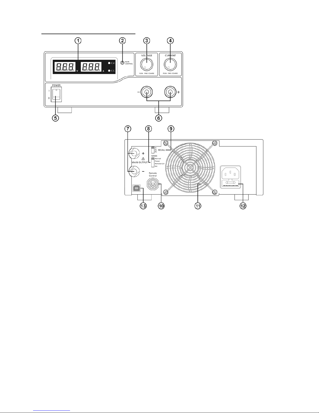
5. CONTROLS AND INDICATORS
(1) LED panel meter display with CC/CV Indictor
(2) Rear Control Indicator (lights up when using Preset/ Remote Control/ Set mode)
(3) Output Voltage Control Knob (control both the main and auxiliary output voltage)
(4) Output Current Control Knob (control both the main and auxiliary output cur r ent limit)
(5) Power ON/OFF Switch
(6) Aux. output terminal ( max 5A)
Note: HCS-3300: The total rated current (Aux.+Main) is 30A
HCS-3302: The total rated current (Aux.+Main) is 15A
HCS-3304: The total rated current (Aux.+Main) is 8A
(7) Output Terminal (Rated 30A for HCS-3300/ Rated 15A for HCS-3302/ Rated 8A for HCS-3304)
(8) Mode Selection Switch (Normal, Preset, Remote Control, Set Modes)
(9) Recall Selection Switch
(10) Remote Control Terminal
(11) Cooling Fan Air Intake Grille
(12) AC Input Plug
(13) USB port
(for access to computer to run cyclical operation with programmable voltage, current, period time and cycle)
Front
Rear
6. CONTROL MODE SELECTION
There are 4 modes, Normal, Preset, Set and Remote Control mode for the power supply.
Slide the Mode Selecti on Switch (8) to your desire d Mode.
The power supply is factory preset to Normal Mode with maximum current level CC.
6.1 Normal Mode
This is the factory preset mode and the power supply output V, I, are controlled by the dual acti on volume knobs.
Push the knobs to toggle t he coarse and fine tuning, notice the subtle changes in brightness of relat ed LED.
Adjust the knobs to your desired values by trying coarse and fine tuning.
To check the preset current level, jus t turn the Current Knob l ightly in any direction.
The display will resume its normal brightness after few seconds to double confirm your adjustment.
6.2 Preset Mode
a. In this mode, the Rear Control Light is on to indicate panel V & I controls are de-activated.
b. There are 3 preset output P1/ P2/ P3 at the Recall Selection Switch (9)
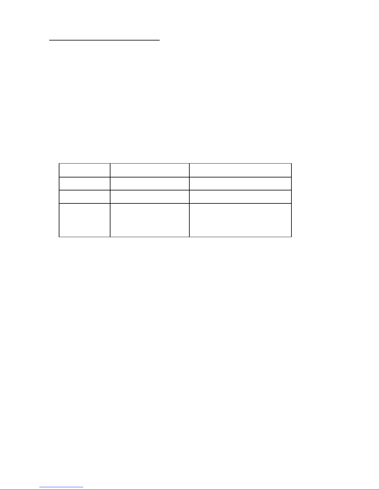
c. The preset values are factory set as following table.
d. End user can set his own output rating, please refer to paragraph 6.3
Recall No.
Output Voltage
Output Current
P1
5V
Maximum
P2
13.8V
Maximum
P3
HCS-3300: 15V
HCS-3302: 25V
HCS-3304: 55V
Maximum
6.3 Set Mode – First enter i nto the Set Mode by pushing Switch (8) to Set Mode slot.
The power supply is then ready to be preset.
6.3.1 To define the preset output P1/ P2/ P3.
a. Select the Recall Switch (9) to the position P1, P2 or P3 which you wa nt to set
b. Adjust the front panel voltage control knob to set your desired voltage value
c. Adjust the front panel c urrent control knob to s et your desired current limit value
d. Repeat the procedure for remaining recalls P1, P2, P3 if desired.
e. Move Mode Switch (8) from Se t to Preset position to confirm your settings.
Remarks:
All the set values in the presets will be kept even after the power supply has been tuned off.
Always check output voltage of Presets before connect to Load
To check the preset values, move Mode Switch (8) to Preset position
Move the Recall Switch (9) to P1, P2 or P3.
The V and I settings of corresponding RECALL P1, P2, P3 will be show on the panel meters.
It is more ease to setup these preset values by using PC software. After set values in PC software and save. Use
Recall switch to use it.
6.4 Analogue Remote Control Mode
To control the output voltage and current by remote control connector (10)
Please refer to paragraph 8
7. Using the power supply
7.1 This series has 3 models. Make sure you have used the correct one.
They have di fferent output voltage range and current as follo wing:
Model Number
Output Voltage Range
Total Rated Current
HCS-3300
1 ~ 16V
0 ~ 30A
HCS-3302
1 ~ 32V
0 ~ 15A
HCS-3304
1 ~ 60V
0 ~ 8A
7.2 Check the rating label of the power supply and make sure it complies with your AC mains voltage.
Connect the power supply to the AC Mains using the provided power cord.
Make sure the Mode Switch (8) is at Normal Position.
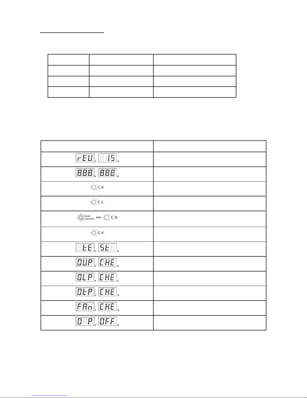
Below table to show the self test sequence
Self test display and Sequence
Test contents
To show software version
Segment check
C.V. Indicator check
C.C. Indicator check
Rear control indicator check
Return to C.V.
Start to check
Over voltage protection check
Over load protection check
Over temperature protection check
Fan check
Output off (remote control mode)
7.3 The power supply will perform a series of self checks when it is switched on.
The LED and o t her ind i ca to rs o n t he fro nt p a nel wi l l b e o n by turn. Whe n t he co o li n g fan is being checked, a hig h
speed wind noise can be heard.
After the self checks, the CV, V and A LED indicators are lit up displaying voltage and 0.0 curre nt. To find out
about the set C C current l evel, just turn t he curre nt contro l knob one click in e ither di rection. The cur rent disp lay
returns to 0.0 after a few seconds.
7.4 Using the control knobs
The rotary encoder control knobs have fine and coarse tuning with clicking movement.
Push the knobs to toggle between coarse and fine tuning, notice the subtle changes in brightness of related LED. .
Adjust the knobs to your desired values by trying coarse and fine tuning.
The display will resume its normal brightness after few seconds to confirm your adjustment.
7.5 Connect the equipment to the power supply. Red (+) is connected to the positive polarity input of the equipment
and Black (-) is connected to the negative polarity input of t he equipment.
7.6 Switch on the power supply first and the panel meter & green CV Indicator should light up again.
7.7 Switch on the equipment and the panel meter & green CV Indicator should still remain in green.
7.8 You can now operate the equipment.
When an oper ation is finished, switc h off the equipment first and then swit ch off the p ower supply.
7.9 Manually zeroing Current Meter Offset
The po wer suppl y will a uto -zeroing the current meter offset when powered up. In case it is needed to reset current
meter to zero during test and you do not want to restart power supply. You can manually reset it to zero in menu
mode.
Press and hold Voltage Control Knob for 30s to enter MENU mode. It shows
Rotate Curr e nt Control Knob until the Current meter showing
Then press Current Control Knob once to confirm. The “YES” will be lighted after successful zeroing current
meter offset.
Finally, pre ss Vo ltage Control Knob to exit MENU mode.
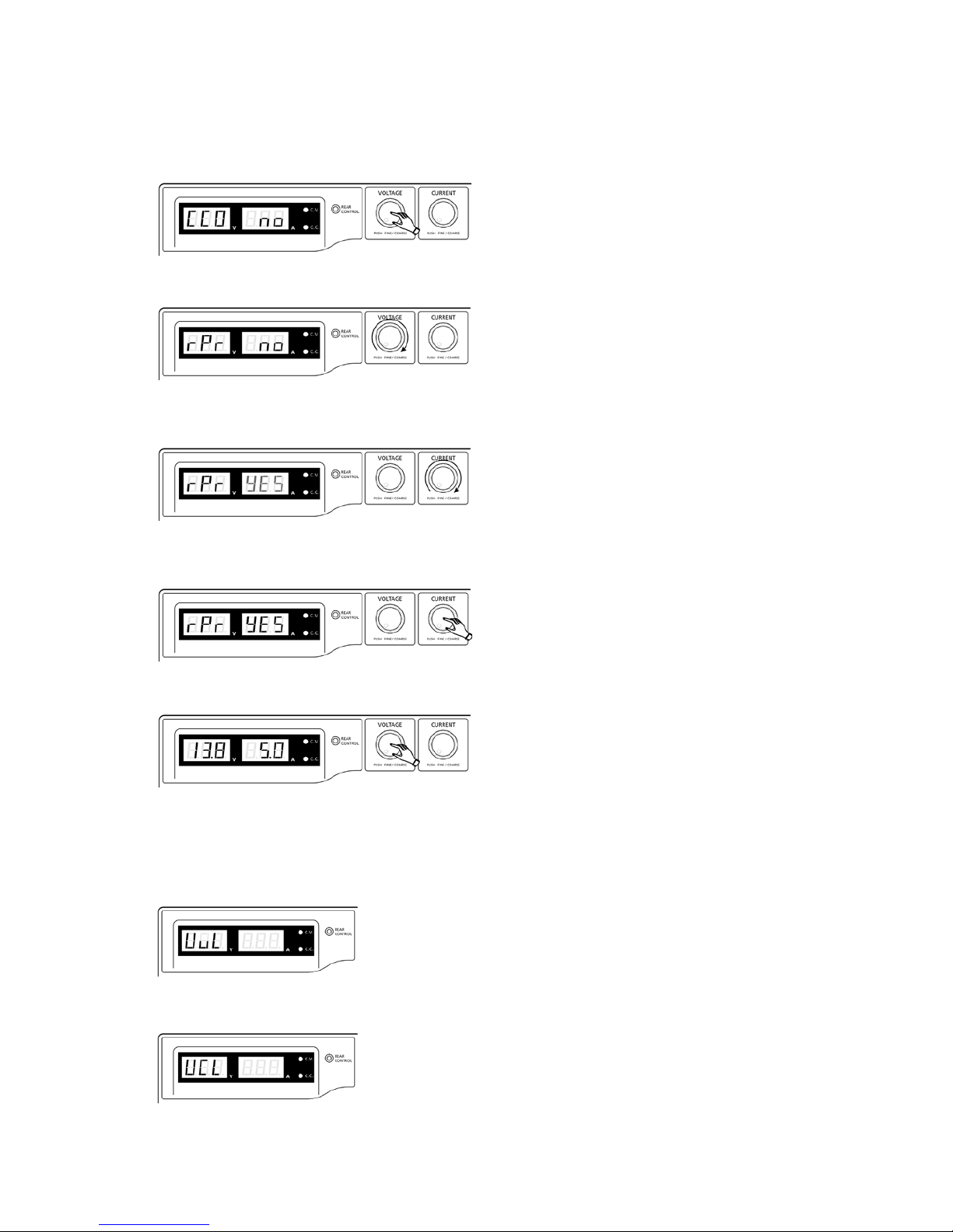
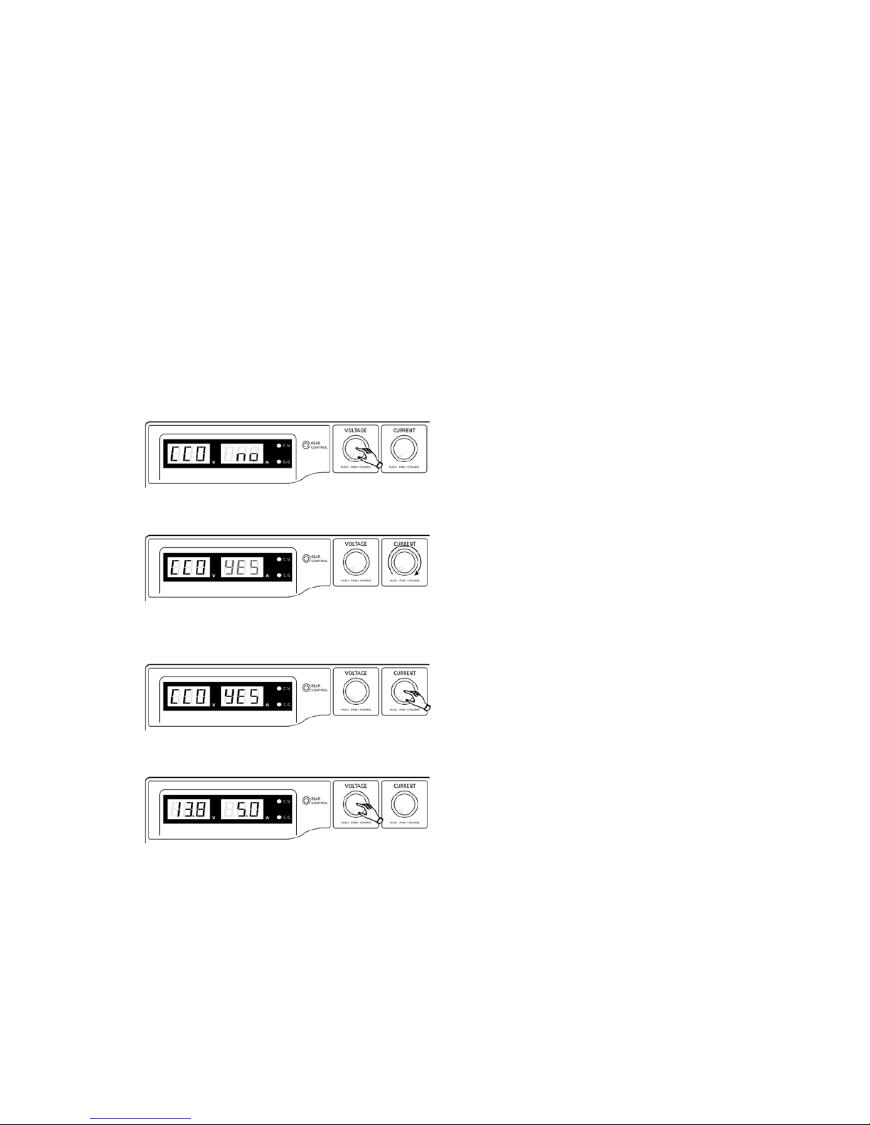
7.10 Reset 3 preset output P1/ P2/ P3 to factory default value
In session 6.3, you learning how to set 3 preset output to you preferred value. In case you need to reset it to factory
default, you can do it in MENU mode.
Press and hold Voltage Control Knob for 30s to enter MENU mode.
When it is showing “CCO”, rotate Voltage Contro l K no b until Voltage meter showing “rPr”.
The Current meter is showi ng “no” at this time. Then ro tate Current Control Knob until Current meter showing
“YES”.
Pre ss Current Control Knob once to confirm. The “YES” will be lighted after preset output being reset to factory
default value.
Finally press Vo ltage Control Knob to exit MENU mode
7.11 Upper Voltage Limit (UVL) a nd U pper Current Limit (UCL)
The power supply has Upper Voltage Limit and Upper Current Limit setting. These value can ONLY be set
through PC software.
When increasing output voltage settin g and reach se t UVL value. The voltage dis play will show
When increasing output current setting a nd reach set UCL va lue. The current display will show
 Loading...