

Manson Engineering Industrial DD105, DD107 Operating Instruction
DC – DC CONVERTER
DD105
DD107
OPERATING INSTRUCTION
■ SAFETY PRECAUTIONS
GENERAL
1) Please read through this operating instruction care-
fully and follow the instruction to prevent from abuse
or misuse. This instruction must be kept to refer
anytime in need.
2) The DD-105 and the DD107 are specially designed
DC-DC converter to use DC13.8V operated radio
equipment sourcing from DC24V outlet providing 5A
continuous operation (DD105) or 7A continuous
operation (DD107).
Note : Continuous operation to be 8(eight) hours
under 24V input at 25°C.
NO RESPONSIBILITY is extended to other than
above applications and/or use.
3) Over Voltage Protection
When DC16V ±0.5V is appeared at the output
terminal, the input voltage will be automatically shut
down to protect the unit.
4) Over Current Protection
When the output current comes over the limitation,
the output voltage and current will be automatically
reduced to protect the unit.
■ CAUTION
1) DO NOT use for equipments require higher current
input than the designed value otherwise it may
damage the unit.
2) DO NOT use this unit for charging battery.
3) DO NOT use for lamps or motorized equipment
which require high current input at starting as it may
damage the unit.
4) DO NOT replace the fuse before ceasing problems
and the assigned value of fuse must be taken in
place.
5) DO NOT feed input voltage other than DC20V –
DC30V as it may damage the unit. The input
voltages specified here are for the purpose of
operationble application only.
6) DO NOT start unit while the radio is being
transmitted as it may damage the unit.
7) NEVER touch the heatsink panel during the unit is
powered. Touching it may burn your hands or part of
your body by high temperature.
8) NO DC24V output can come out from the input
when feeding DC12V to the output.
9) BE SURE wiring connections otherwise it may
damage the unit. While cable is for INPUT(+) and
Black cable is for INPUT(-). Red cable is for
OUTPUT(+) and Black cable is for OUTPUT(-).
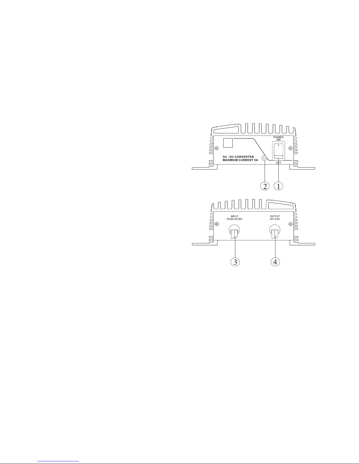
■ CONTROLS AND FUNCTIONS
(1) POWER SWITCH
Turning ON, the indicator lights up.
(2) OPERATE LED
Light-up when unit is operate.
(3) INPUT CABLES
White is for (+) positive and Black is for (-) negative
directly from the battery.
(4) OUTPUT CABLES
Red is for (+) positive and Black is for (-) negative.
■ CONNECTION AND OPERATION
1) Turn OFF the unit.
2) Connect the input white cable to (+) and the input
Black cable to (-) of 24V battery firmly.
3) Turn OFF the equipments and connect Red (+)
output cable of the unit to the positive polarity input
of the equipment to be powered.
4) Connect Black (-) output cable of the unit to the
negative polarity input of the equipment to be
powered.
5) Turning ON the unit, LED lights up yellow, then turn
ON the equipment to be powered.
6) When an operation is over, turn OFF the equipment
being powered first. Then trun OFF the unit.
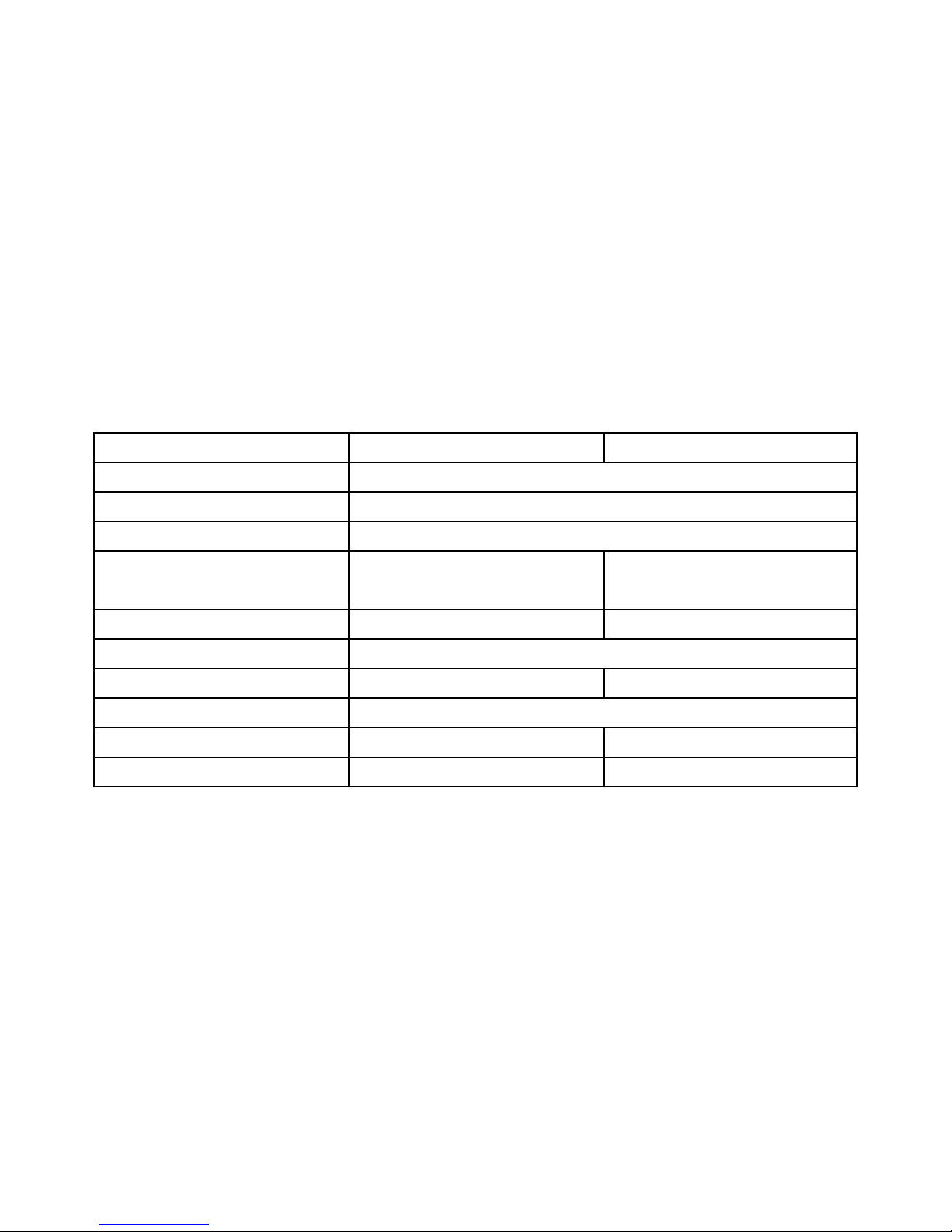
■ SPECIFICATIONS
■ FEATURES
1) Overload Protection
Over Voltage Protection and Over Current
Protection circuitry are adopted to prevent from
overload.
Note : When the protection circuit works, disconnect
the equipment. Keeping the may damage the unit or
even may hurt you.
2) High RFI Stability
Designed for high protection circuitry against RFI
( Radio Frequency Interference ) provided you a
stable operation. These units comply CE EMC
Directive 89/336/EEC.
7673-0105-0000
DD105 DD107
INPUT VOLTAGE
DC 20V - DC30V
OUTPUT VOLTAGE
DC13.8V ±0.5V
O.V.P. SETTING
DC16V ±0.5V
OUTPUT CURRENT
( CONTINUOUS )
5A FOR 8 HOURS UNDER
DC24V INPUT AT 25°C
7A FOR 8 HOURS UNDER
DC24V INPUT AT 25°C
CURRENT LIMITING
6 ±0.5A 9 ±0.5A
STANDBY CURRENT
70mA at no loading
FUSE
7A 10A
COOLING SYSTEM
Air Convection
DIMENSIONS
125(W) x 45(H) x 100(D) 125(W) x 45(H) x 120(D)
WEIGHT
0.55kg 0.62kg
* Specifications are subjust to change with piror notice.
 Loading...