

Page 1

CLASSIC SERIES
RATING/SPECIFICATIONS
For all electrical power and IP ratings refer to the fan rating and wiring label.
All fans are double insulated,manufactured to comply with:
EN60335-2-80:1997 and are CE marked
IMPORTANT
• Isolate the main supply before making any electrical connections.
This system should be installed by a qualified electrician.
• When fitting through an external wall, an external grille must be fitted
at all times.
• Fan should only be installed by fixed wiring, a flexible cord should not
be used.
• The appliance is not intended for use by young children or infirm
persons without supervision.
• Young children should be supervised to ensure that they do not play
with the appliance.
• Precautions must be taken to avoid the back-flow of gases into the
room from the open flue of gas or other open-fire appliances when
mounted in outside windows or walls.
INSTALLATION INSTRUCTIONS
MANROSE XFS230/300 & XPS230/300 RANGE
OF EXTRACTOR FANS.
Thank you for selecting the Manrose XFS/XPS range. Please read all instructions
before commencing installation.
NOTE:(i) For best results this Extractor Fan should be fitted as high
on the wall as possible, or if preferred, on the ceiling. (Not
Pullcord Model)
(ii) Do not install the unit within a shower cubicle or anywhere else
where there is a high risk of the fan being sprayed with water.
(iii) Switch off mains supply before making electrical connections.
If in any doubt contact a qualified electrician.
(iv) This fan is double insulated and does not require an earth.
(v) When installing fan through an external wall, an external wall
grille must be fitted at all times.
We reserve the right to change specification without prior warning
Manrose is proudly distributed by Simx Limited
PO Box 14 347, Panmure, Auckland, NZ. Technical Support (09) 259 1662
e: sales@simx.co.nz | www.simx.co.nz | www.manrose.com.au
PUB7145 iss:06 04/14
1. Cut a hole in the wall to suit the fan and duct. Please note that the
maximum hole size is equal to the diameter of duct (see column E in
dimensions table). If the fan is to be fixed in the ceiling ensure that
the hole is between the joists.
2. Fit suitable ducting flush to the plaster.
3. Remove the cover from the fan by removing the two small screw
caps on the front cover and remove the two retaining Philips screws.
4. Hold the body of the fan against the wall or ceiling and mark the
four screw holes and the cable entry.
IMPORTANT: Ensure that the fan is square on wall or ceiling.
5. Bring power cable into position, as marked. Allow an extra 350mm
protruding to facilitate connection. Fan should only be installed by
fixed wiring, a flexible cord should not be used.
6. When installing the external grille first take the grille insert out using
a flat screwdriver (as shown in Fig 3), and then drill 4 holes in the
corners, mark screw holes on the wall, and fix external grille (see Fig 4).
Page 2
B
D
10" Ø
IN
OUT
C
SIDE ELEVATION
B
DIMENSIONS XFS230/300 RANGE
FIG 1
FIG 2
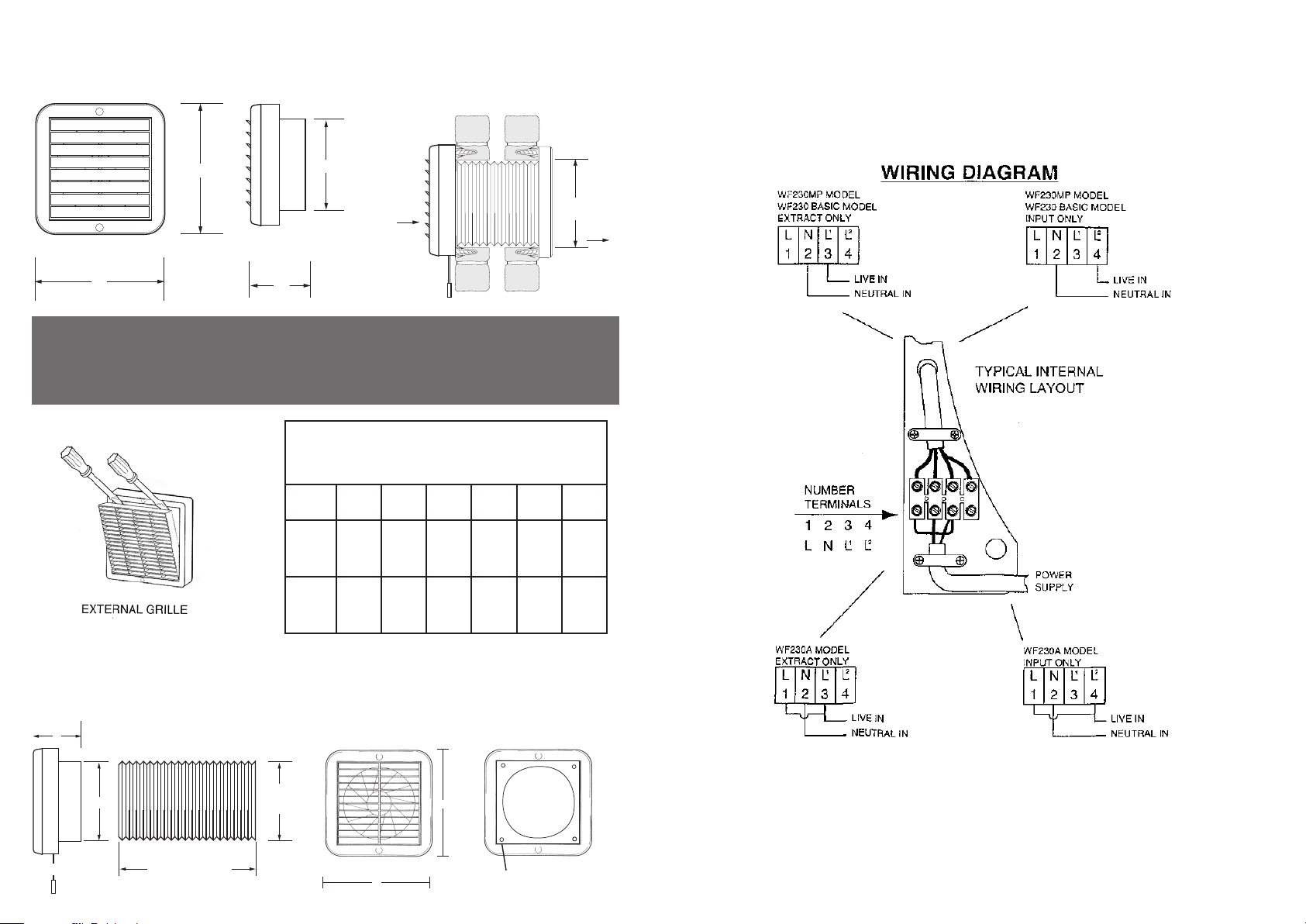
WIRING DIAGRAM
Typical Internal Wiring layout - All Base Model
C
B
THROUGH WALL FIXING
FRONT ELEVATION
A
IMPORTANT NOTE:
A
SIDE ELEVATION
If equipped, Automatic Shutters incorporate a thermally activated mechanism that
opens and closes the shutters. When the unit is turned on and off shutters will take
approximately 45 seconds to respond.
FIG 3
KEY TO DIMENSIONS FOR
XFS230/300 AND XPS230/300 RANGE
A B C D E F
XF/XP
230
XF/XP
300
286mm112mm235mm255mm265mm230
mm
365mm150mm285mm310mm300mm285
mm
DIMENSIONS XPS230/300 RANGE
FIG 4
B
E
External
Diameter
SIDE ELEVATION
F
Extends up to 400mm
EXTERNAL GRILLE
A
A
Note:
Extraction of air - Live supply connected to terminal 3 (L1) as shown
Supply of air - Connect live to terminal 4 (L2).
Holes to be drilled
 Loading...