

Page 1
MANUAL
INTELLIVENT
®
2.0
EN
DESIGNER SERIES
Page 2

Thank you for choosing this product from Manrose.
Before installing and using the fan, read through these
instructions. Keep them safe for reference in future.
SPECIFICATIONS
IMPORTANT
All electrical work must be carried out in accordance
with local and national electrical codes as applicable. We
strongly recommend that this light tting is installed by a
registered electrician.
Always switch power o prior to installation. A means of
mains power isolation must be installed on the circuit
for the purpose of safe access for any internal cleaning,
recalibration, or maintenance.
This light tting is not intended for use by persons
(including children) with reduced physical, sensory or
mental capabilities, or lack of experience and knowledge,
unless they have been given supervision or instruction
concerning use of the appliance by a person responsible
for their safety. Young children should be supervised to
ensure that they do not play with the appliance.
There are no user servicable parts in this light tting.
Any changes or modications made or attempted to
this product, without the prior written approval of the
manufacturer, will void any and all stated warranties.
Intelivent 2.0 Specications,
MANROSE
FAN5901 INTELLIVENT 2.0 STARTER KIT WHITE
100-240V~50-60Hz
MAX WATTS: 8W
IP44 CLASS II
2
Page 3

CONTENTS
4 Description of functions
5 Installation guide
1 Contents
2 Installation
3 Connection
4 Installation options
5 Connecting a pull cord switch
6 Factory setting
7 Setting functions
10 Advanced functions
• Setting humidity sensitivity mode
• Pause function with momentary switch
12 LED indicators
13 Maintenance
15 Warranty
15 Recycling
16 Accessories
17 Technical data
18 Troubleshooting guide
3
Page 4

DESCRIPTION OF FUNCTIONS
• Automatic moisture detection system
Intellivent is equipped with fully automatic humidity
control.
• Timer
Selectable delay time – 5, 15 or 30 minutes.
• Speed control
The intergrated speed control allows you to adjust the
noise level and capacity to meet your needs.
• Continuous operation
Continuous ventilation mode
• Airing function
If the fan has been inactive for 26 hours, an airing
programme will run for 60 minutes.
• Pause function
The fan can be paused for one hour using the pull cord.
• LED indicators
A light-emitting diode with three dierent colours
indicates which mode the fan is in at any one time.
• 12-volt motor
Long-life DC motor. This type of motor also runs silently.
4
Page 5
INSTALLATION GUIDE
1 Contents
The packaging should contain the following:
• Fan
• 2 adapters, 1 x Ø98 mm and 1 x Ø118 mm
• Manual
• Accessory bag with 4 screws and plugs, a pull cord with
toggle, and insulation for the standard cable type (FK).
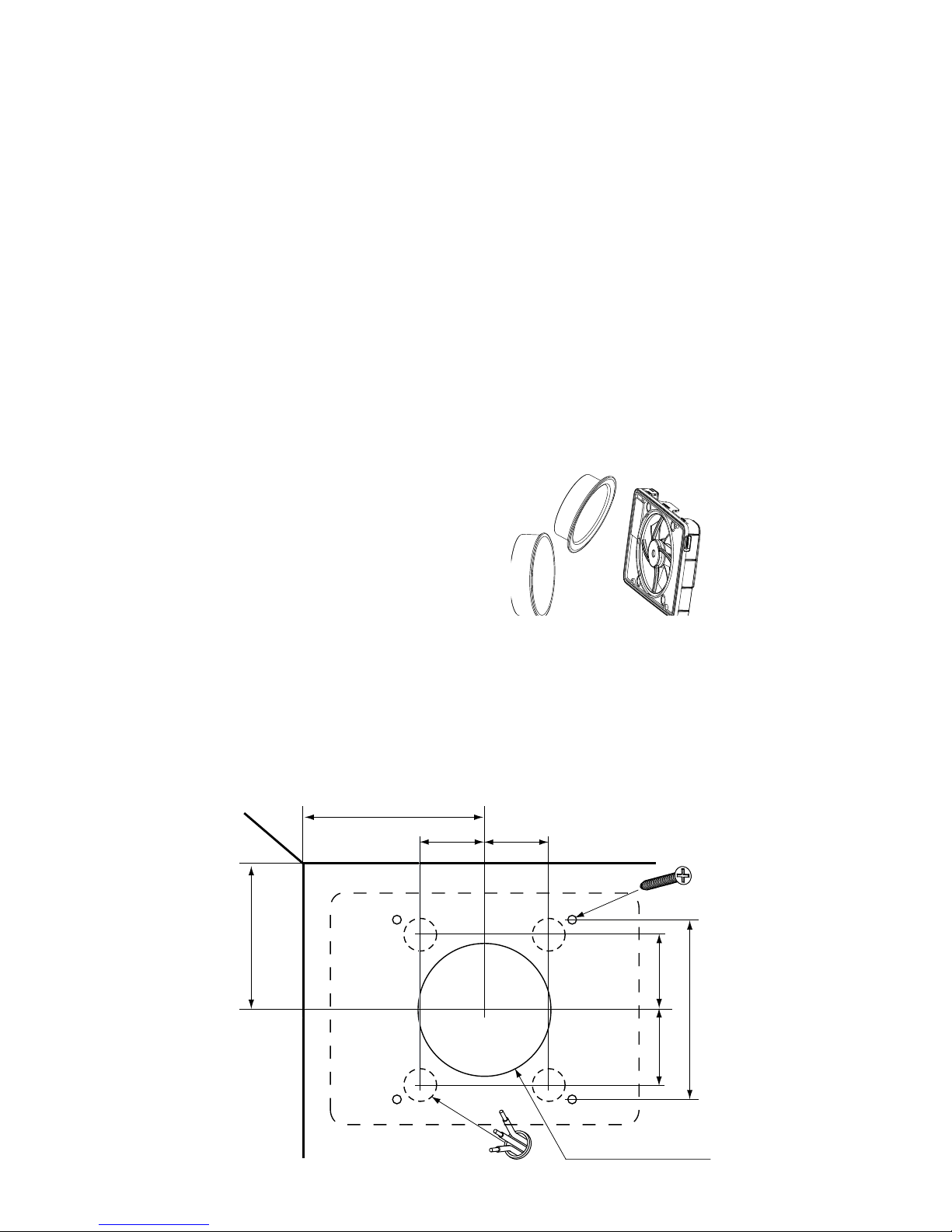
2 Installation
The fan can be installed on a wall or on a ceiling. See the
diagram below for installation dimensions. The fan must
not be installed in an environment where the temperature
exceeds 50°C. Attach an appropriate adapter to the fan's
chassis, Ø98 (1) for a Ø100 duct or Ø118 (2) for a Ø125 duct.
The fan can also be installed and
used without an adapter, so
that it is mounted completely
on the surface, e.g. in the case
of ducts less than Ø98.
When installing the fan, check that there is a seal between
the pipe/duct and wall/ceiling to prevent humid air from
penetrating the wall or ceiling. Use the accompanying
screw and plug, if necessary.
Ø100 alt. Ø125
45
55
Min 120
Min 80
45
55
#124
Alt. x4
x4
1
2
5
Page 6
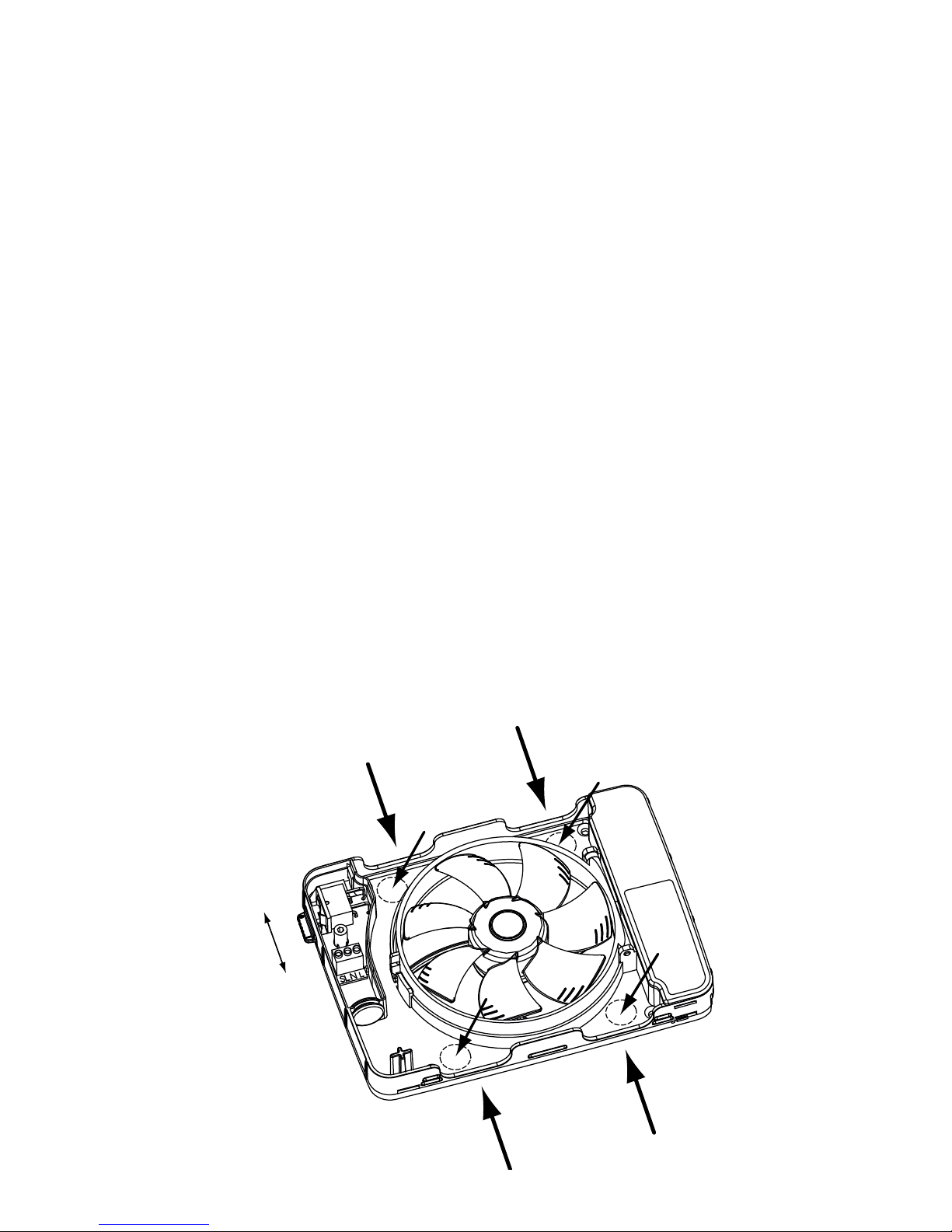
Cable entries
A=surface
B=concealed
3 Wiring
• All electrical work must be carried out by a registered
electrician.
• The fan is double insulated and must not be earthed.
• The fan is tted with a multi-pole switch and does not
require a pre-wired external switch.
1 Push the multi-pole switch up to position 0 – OFF.
2 The cable can be installed either along the surface using
entries A in the chassis or concealed using the B inlets
in the chassis. Both options are shown below. Use the
insulating sleeve supplied for the cable.
3 If you use any of the B inlets, remove the concealed
round plastic cover by tapping inside the break-o
notch from the inside out to the back with a screwdriver,
for example.
A
A
A
A
B
B
B
B
ON
OFF
6
Page 7
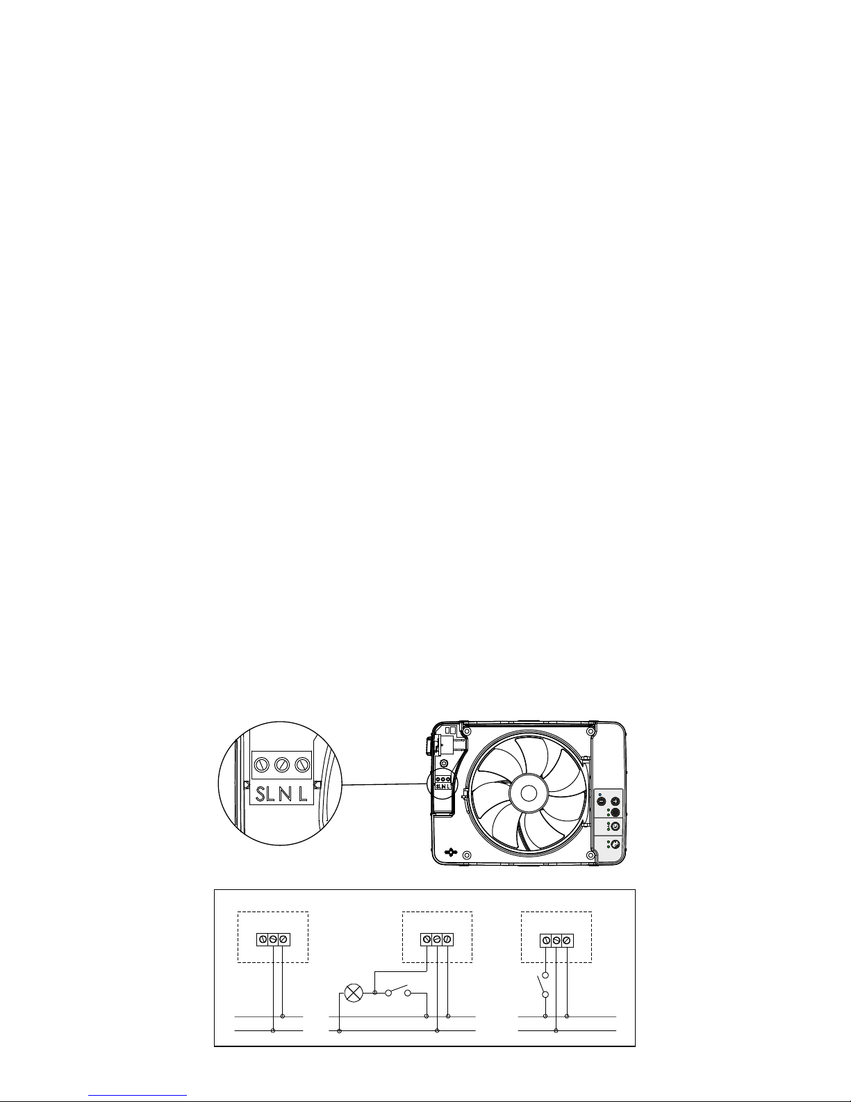
4 Installation options
The fan can be installed in any of three ways
depending on the desired function, as detailed below:
1 Humidity control only, see diagram 1
The fan is connected to constant phase (L) and
neutral (N) for automatic humidity control.
The timer can be activated manually by installing a pull
cord and pulling it (see page 8).
2 Humidity control + timer with light switch, see
diagram 2
The fan is connected to constant phase (L) and
neutral (N) for automatic humidity control.
Switched live (SL) is connected to activate the fan's
timer, i.e. when the bathroom light is switched on. This
option provides a 90-second start delay.
3 Humidity control + timer with retractive switch, see
diagram 3
The fan is connected to constant phase (L) and
neutral (N) for automatic humidity control.
Switched live (SL) is connected to activate the fan's timer
using a retractive switch.
This option gives direct start-up of the fan.
Wiring diagram
TIMER
HUMIDITY
TIMER
CONSTANT
5
15
30
SPEED
SILENT
MAX
S
MIN
1 2 3
SL N L SL N L
SL N L
L
N
L
N
L
N
TIMER
HUMIDITY
TIMER
CONSTANT
5
15
30
SPEED
SILENT
MAX
S
MIN
7
Page 8

5 Connecting the pull cord switch
A pull cord can be installed for activating the timer
manually or for pausing the fan. Remove the mounting
plate using a screwdriver, and thread the accompanying
pull cord through the hole.
• Once installation is complete, push the safety switch
down to position I – ON, to make the fan active again.
When the fan is connected to the power supply, it performs a
self-test where electronics, LEDs and operation of the motor
are all tested. The fan is now ready for use.
NB!
Use an ordinary round le to
create a smooth cut-out at
a suitable place in the front
cover.
Do NOT use pliers or similar
tools, as these may cause the
cover to crack.
8
Page 9

6 Factory setting
• timer – 5 minutes
• humidity speed – silent (70% of max.)
• timer speed – 70% of max.
• constant operation – o
Restore factory settings
Hold the S-button in for
a minimum of 5 seconds.
7 Setting functions
Possible adaptation to meet your needs:
1. Setting fan speed for timer operation.
Press the S-button until the timer light comes on.
Use the SPEED buttons to set the speed.
Restore the factory default timer speed by pressing both
the SPEED buttons simultaneously.
2. Delay time
Set the timer to 5, 15 or 30 minutes.
3. Humidity mode / humidity
Set to silent or max. capacity – small or large bathroom.
4. Continuous operation
Press the S-button until the "CONSTANT" light comes
on. Select the fan speed using the SPEED buttons.
To turn o continuous operation: press the S-button
until the "CONSTANT" light goes o.
TIMER
HUMIDITY
TIMER
CONSTANT
5
15
30
SPEED
SILENT
MAX
S
MIN
9
Page 10

ADVANCED FUNCTIONS
Selecting humidity sensitivity mode
Bathroom climates may vary depending on a number of
factors: room size, the presence of any natural draught
ventilation, temperature, etc. These factors may aect the
fan humidity response, causing it to start too quickly or
too slowly.
The factory setting is position 2: normal humidity
response, which works best in most cases.
1) Press the Speed + and
Humidity mode buttons
simultaneously (the blue and
yellow LEDs ash quickly).
Press the Humidity Mode button until the desired humidity
sensitivity mode is selected.
Position 1: the Silent LED comes
on – fast humidity response.
Position 2: the Max LED comes
on – normal humidity response.
Position 3: The Silent and Max
LEDs come on together – slow
humidity response.
Position 4: Both the Silent and
Max LEDs stay o – humidity
control is deactivated.
2) Press the Speed + and
Humidity Mode buttons at the
same time (The blue and yellow
LEDs stop ashing).
TIMER
HUMIDITY
TIMER
CONSTANT
5
15
30
SPEED
SILENT
MAX
S
MIN
TIMER
HUMIDITY
TIMER
CONSTANT
5
15
30
SPEED
SILENT
MAX
S
MIN
TIMER
HUMIDITY
TIMER
CONSTANT
5
15
30
SPEED
SILENT
MAX
S
MIN
10
Page 11

Pause function using momentary switch
You can pause the fan for one hour by engaging an external momentary switch. This can be connected as shown in
diagram 3 on page 7.
With this function selected, you will be unable to use the
delayed start via switched live (lighting) function connected
to SL
Activation
1 Press the Speed + and Humidity Mode buttons
simultaneously(the blue and yellow LEDs ash quickly).
2 Press the timer button and hold it in for 5 seconds until
the 5 min LED comes on.
3 Press the Speed + and Humidity Mode buttons at the
same time (The blue and yellow LEDs stop ashing).
Deactivation
1 Press the Speed + and Humidity Mode buttons
simultaneously (the blue and yellow LEDs ash quickly).
2 Press the timer button and hold it in for 5 seconds until
no timer run-on LEDs are illuminated.
3 Press the Speed + and Humidity Mode buttons
simultaneously (the blue and yellow LEDs ash quickly).
TIMER
HUMIDITY
TIMER
CONSTANT
5
15
30
SPEED
SILENT
MAX
S
MIN
TIMER
HUMIDITY
TIMER
CONSTANT
5
15
30
SPEED
SILENT
MAX
S
MIN
11
Page 12

LED INDICATORS
LED – what is the fan doing?
Intellivent is equipped with a three-colour LED
indicator: yellow, blue and purple.
These three colours tell the user what the fan is doing and
which function is currently controlling the motor.
• No LED on
The fan is o or is running continuously.
• Blue LED on
The fan is running – the humidity sensor has
detected increased humidity in the room.
• Blue ashing LED
The fan is running – the fan sensor has detected that it
can reduce its reference values for humidity in the room.
• Yellow LED on
The fan is running – timer control has been activated.
• Yellow ashing LED
Timer control with delayed start has been activated by
the light switch.
The LED ashes for 1.5 min. before the fan starts.
• Purple LED on
The fan is running – the airing function has been
activated.
• Yellow and blue LEDs slowly ash alternately
Pause function has been activated.
• Yellow and blue LEDs quickly ash alternately
Programming mode has been activated.
12
Page 13

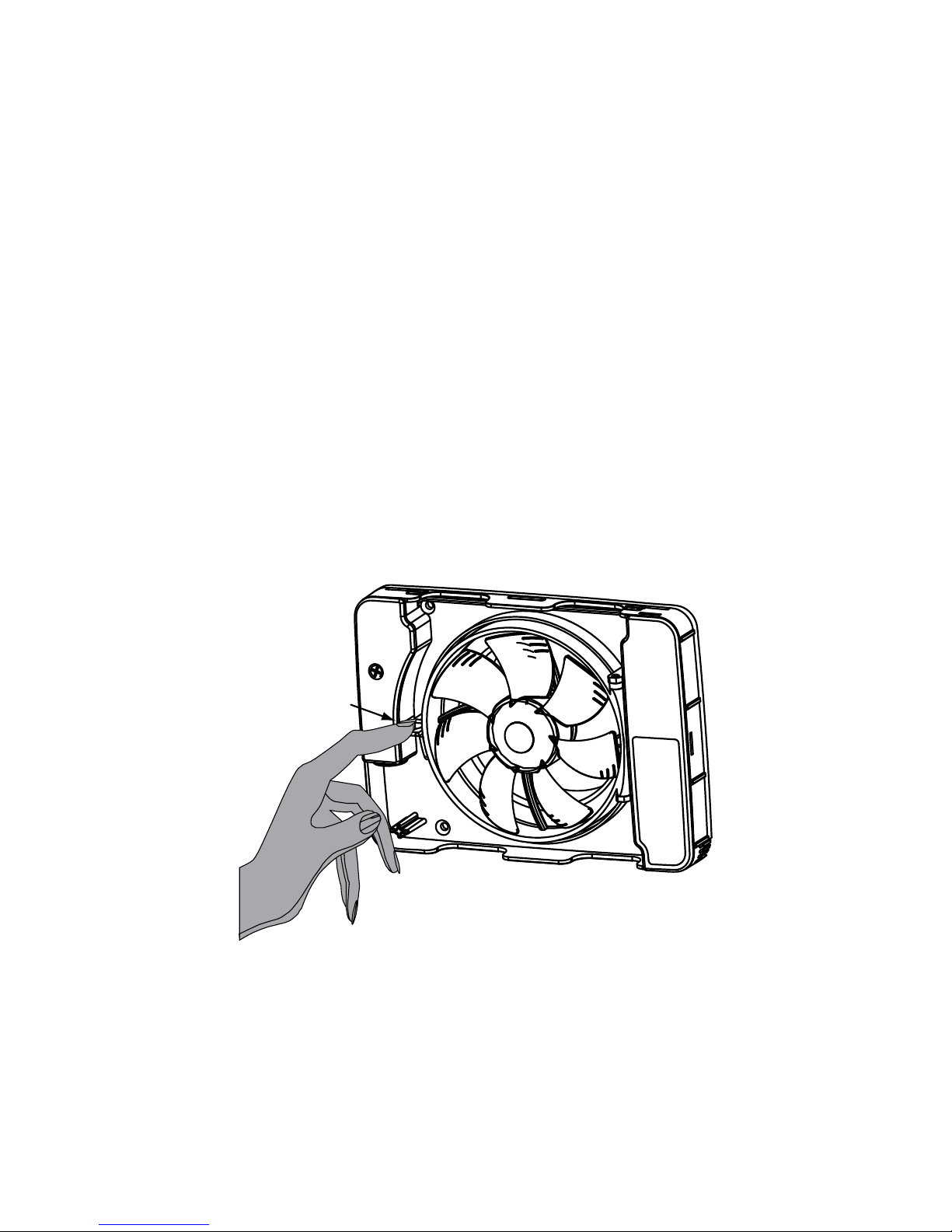
MAINTENANCE
Clean the fan at least twice a year, or as required.
Disconnect the power supply to the fan by pushing the
multi-pole switch up to position O - OFF.
The fan is tted with a removable propeller. Press in the
centre using your thumb, grip the fan wings and pull o
the propeller. The fan's "swing out" function is also useful, as it provides easy access to the duct. Press the motor
mount ring's snap-in catch and swing out the motor/
blades.
When cleaning the fan, pay particular attention to the
blades if these are dirty. Otherwise, there is a risk of
imbalance and hence increased noise and a reduced
life span for the motor bearings.
Clean the fan's blades with a brush or paintbrush.
Clean the fan cover with a polishing cloth moistened
with water and possibly a mild detergent.
NB! Never use solvents or similar products on any part of
the fan, as there is a risk of them damaging the fan's plastic
components!
OFF
13
Page 14
Never submerge the fan in water, as there is a risk that this
could damage the fan's motor.
After cleaning, swing the motor mount ring back into
position and lock it by securing the snap-in catch.
Switch the multi-pole switch back on by moving the
switch down to position 1 – ON.
If maintenance of the fan is not performed as specied
above, the product warranty will be null and void.
Click!
14
Page 15

WARRANTY
We provide a 5 year warranty against
manufacturing defects.
For the warranty to be valid, proof of
purchase is required and the fan:
- must be assembled and installed in accordance
with the installation guide in this manual
- must have been maintained according to the
maintenance instructions in this manual
- must be installed in a normal residential environment
- must be connected to a voltage of 240 V AC ~ 50Hz
- must not have been exposed to lightning or
abnormal power surges
- must not have been subjected to tampering
- must have been installed in a zone rated as IP44
- must not have been installed in an environment where
the temperature exceeded 50° Celsius.
RECYCLING
The product is marked with the WEEE symbol,
which indicates that it must not be disposed
of with household waste, but must be recycled
at a suitable recycling location.
15
Page 16

ACCESSORIES
There are a number of accessories available for Intellivent to
help you, as a user, install the product as smoothly as possible. Please refer to www.simx.co.nz, keyword "Intellivent",
for all the latest accessories for your Intellivent.
Below are some examples of accessories.
Pipes
for sizes
100 and 125
Cover plate
190 x 240 mm
white and black
Plastic grille
for sizes
100 and 125
Metal grille
for sizes
100 and 125
Cold surge protection
for sizes
100 and 125
YVG100 and 125
Feed-through with
cold surge protection.
For optimum ventilation, you must ensure that
sucient air can enter the bathroom. This is done
either by creating an opening at the bottom of the door or
by installing an air vent in the door or wall.
It is also important to draw fresh air into the house that is
then expelled through the bathroom or laundry room, for
instance.
In this case, it is a good idea to install fresh air vents in bedrooms and in the living room.
16
Page 17

Duct
dimensions
Max/ Silent
Capacity (free
blowing)
Sound pressure
level 3 m
Ø 98 Max 107 m³/h 28 dB(A)
Ø 98 Silent 74 m³/h 21 dB(A)
Ø 98 Constant 42 m³/h 12 dB(A)
Ø 118 Max 134 m³/h 29 dB(A)
Ø 118 Silent 86 m³/h 21 dB(A)
Ø 118 Constant 55 m³/h 13 dB(A)
35
30
25
20
15
10
5
0
0 50 100 150
Ø98 silent speed
Ø118 silent speed
Ø98 max speed
Ø118 max speed
Pa
m³/h
TECHNICAL DATA
Pipe outlet for
concealed installation
Maximum capacity 134 m³/h
Sound pressure level 3 m (Silent mode) 21 dB(A)
Power consumption 2,1 - 5,5 W
Max Watts 8W
Mounting dimensions in wall 0 - 30 mm
Holes 105 -130 mm
Material ABS plastic
Protection rating IP44
Insulation class
Voltage 100 -240 V
Frequency 50-60 Hz
Certicates
Capacity
Ø100 alt. Ø125
45
55
Min 120
Min 80
45
55
#124
Alt. x4
x4
17
Page 18

TROUBLESHOOTING GUIDE
The fan runs non-stop
The blue LED is on constantly
(If the fan has been running non-stop for at least 24 hours)
Check that it is working by opening the bathroom door
and leaving it open for at least half an hour to equalise
humidity levels.
Disconnect the power supply to the fan – move the safety
switch to position 0 – OFF and then back to position I – ON.
The yellow LED is constantly on
If the fan is connected to an external switch for timer
control, switch this o and wait at least 30 minutes.
Disconnect the power supply to the fan – move the safety
switch to position 0 – OFF and then back to position I – ON.
No LEDs on
This is entirely normal if the fan has been set to
continuous operation. No LEDs are on in this mode.
If the fan has not been set to continuous operation,
disconnect the power supply to the fan – move the safety
switch to position 0 – OFF and then back to position I – ON.
Other faults
The fan stops when the light is switched on.
The fan has probably been programmed to pause
on a momentary switch. See page 11 for
deprogramming
The fan does not work as described
Remove the cover and disconnect the power supply to
the fan by moving the safety switch to 0. Then return the
switch to I (On).
If the fan still does not work as described in this guide,
contact your electrician.
18
Page 19

19
Page 20

Page 21

Page 22

is proudly distributed by Simx Limited
PO Box 14 347, Panmure, Auckland, NZ.
Technical Support (09) 259 1662 | e: sales@simx.co.nz
www.simx.co.nz
We reserve the right to change specification without prior warning
PUB1337 iss01 08/15
 Loading...