

Page 1
INSTALLATION INSTRUCTIONS
MANROSE CLASSIC 125mm
EXTRACT-A-LITE FAN RANGE
Installation Instructions
Important: The Halogen Extract-a-lite must not work independently of
the fan.
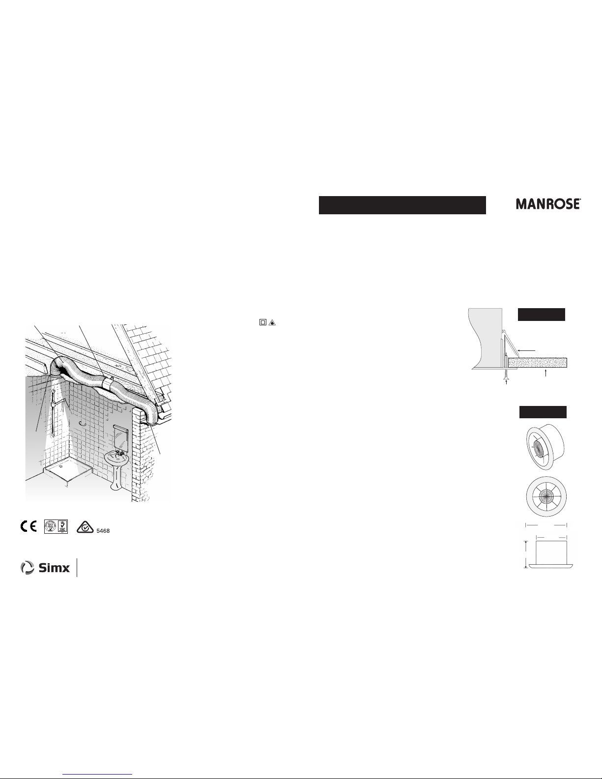
1. Cut a 140mm diameter hole in ceiling, (always ensure the hole is cut
between ceiling rafters and away from any wiring or plumbing). Fix the
Extract-a-lite chassis using the 4 screws provided. Use the fixing clips to
secure the fan in panel walls & ceilings.
2. For the LED models: Connect a suitable driver to the Extract-a-Lite and
to a suitable power supply, ideally to the switched live of the extractor
fan installed. Recommended driver: FAN5342. Replacement lamp:
LHT0221.
For the Halogen models: Connect a suitable transformer to the
Extract-a-Lite and to a suitable power supply, ideally to the switched live
of the extractor fan installed. Recommended transformer: FAN2101.
Recommended lamp: FAN0431.
3. Place the white ceiling cover onto the Extract-a-lite chassis by positioning over
the 3 lugs, and twisting clockwise.
4. Never connect mains direct to the lamp.
5. The t ransfo rmer/dr iver m ust be suitable for 230V AC input.
CAUTION: Disconnect the power supply, and be sure that the lamp
has fully cooled before removing or replacing.
Fixing clip
Ceiling board
Screw
Fan
chassis
When screw is tightened fixing
clip fingers secure the fan
INSTALLATION
Thank you for selecting our Manrose 125mm Extract-a-Lite Fan Kit.
Please read all instructions before commencing installation.
Light Specifications:
LED models: FAN5371- FAN5372
Driver Input: 220-240 VAC
Driver Output: 12VDC
Lamp MR16: 12V / 3W high power LED, 250 beam angle
Halogen models: FAN2037 and FAN2038
Transformer Input: 220-240 VAC
Transformer Output: 12VAC
Lamp MR16: 12V / 50W Halogen, 600 beam angle
DIMENSIONS
165mm
118mm
80mm
CLASSIC SERIES
IMPORTANT
• Isolate the mains supply before making any electrical connections. This system should be
installed by a qualified electrician.
• When fitting through an external wall, an external grille must be fitted at all times.
• Fan should only be installed by fixed wiring, a flexible cord should not be used.
• The appliance is not intended for use by young children or infirm persons without supervision.
• Young children should be supervised to ensure that they do not play with the appliance.
• Precautions must be taken to avoid the back-flow of gases into the room from the open flue of
gas or other open-fire appliances when mounted in outside windows or walls.
Fan Specifications:
Electrical: 220-240V ~50Hz
Airflow: 36l/s (130m³/hr)
Wattage: 20W
Max Temp: 50°C
IP Rating: IPX4
Flexible
ducting
External
Grille
Internal
Extract-a-Lite
The Shower Fan
screwed to the joist
PUB0330 iss03 10/13
We reserve the right to change specification without prior warning
Manrose is proudly distributed by Simx Limited
PO Box 14 347, Panmure, Auckland, NZ. Technical Support (09) 259 1662
e: sales@simx.co.nz | www.simx.co.nz | www.manrose.com.au
Please ensure the corrrect LED lamp and driver OR Halogen lamp and transformer are used
for replacements. The LED model MUST be replaced with an LED lamp and the Halogen model
MUST be replaced with a Halogen lamp. They are not interchangeable.
Page 2
FITTING THE INDUCT FAN
1. Select a suitable place for the axial fan to be screwed to a joist and secure using two screws through
the fixing bracket.
2. Select a suitable position either in the soffit or on an outside wall for the other grille, and cut a 130mm
hole. Attach one end of the flexible duct to the grille with the duct provided and from the outside feed
the ducting through the hole until the grille is flush with the soffit/wall. Secure the grille to the wall as
before. NB: It is best not to cut the flexible ducting until the grille has been screwed to the outside
surface to avoid the possibility of cutting the duct too short.
3. Pull the flexible ducting gently to the discharge spigot of the fan and cut it to length and connect to the
fan. NB: The discharge end of the fan unit is the end where you can see the fan blade clearly.
There is also an arrow on the unit showing the airflow direction.
4. Connect the other piece of duct to the Extract-a-lite and onto the fan. Cut off and discard any excess
ducting. NB: Make sure wherever possible to keep the ducting running in a straight line as this will
improve the performance of the fan.
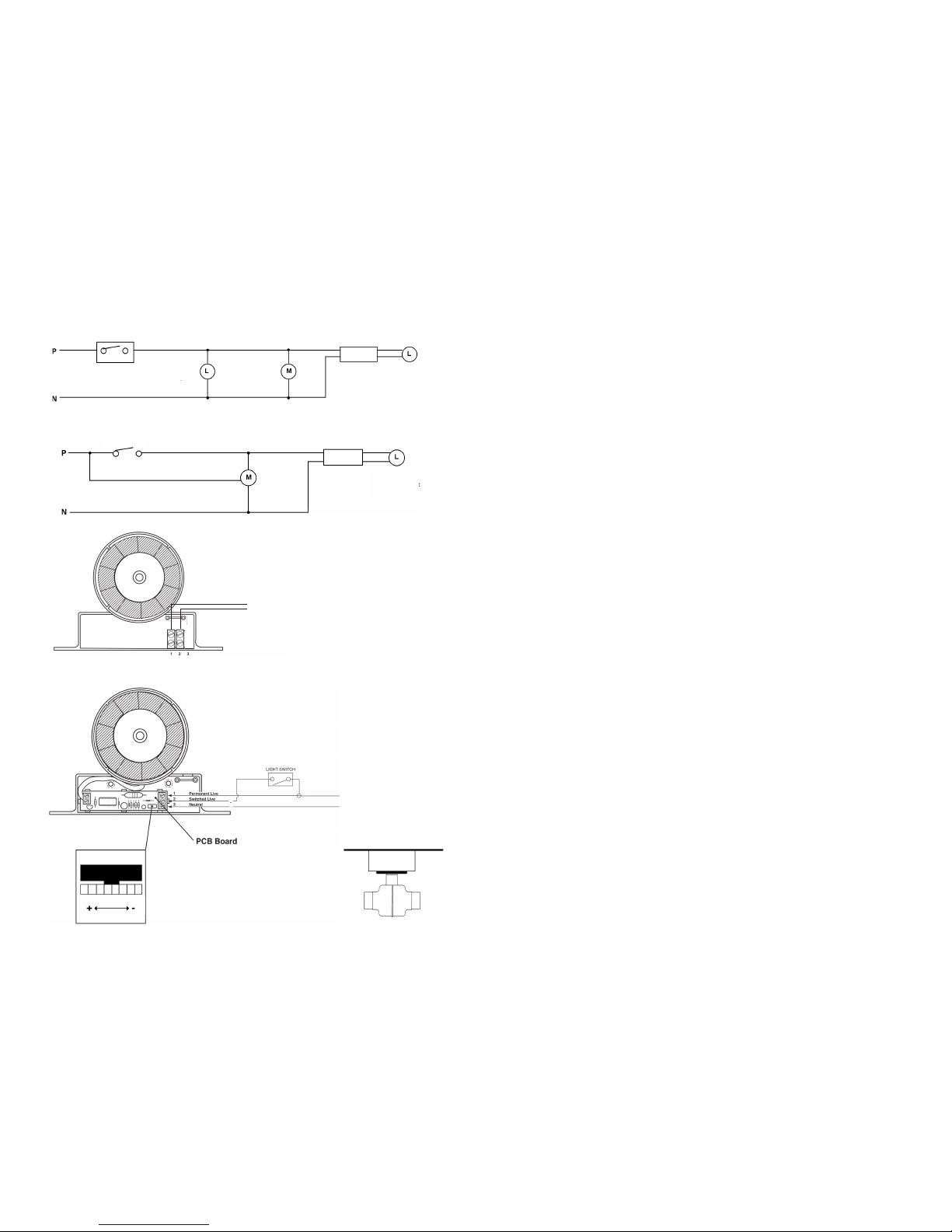
5. Remove the cover on the Fan Bracket and make the electrical connection as follows:
6. Wiring of Standard Model EL125S. Diagram 1 & 3
The fan can be connected to the light switch so that the fan will start when the light is switched on. The
fan should not be accessible to a person using either the shower or the bath.
NB: All wiring must be fixed securely and the cable to the fan should be a minimum of 1mm² in
section. All wiring must comply with current Regulations. This system should be installed by a qualified
electrician.
7. Wiring of Timer Model EL125T Diagram 2 & 4.
The fan can be connected to the light switch so that the fan will start when the light is switched on.
When switched off the fan and Extraxt-a-Lite will continue to run on for between 20 seconds
& 20 minutes (pre-set to 1 minute). The fan should not be accessible to a person using either the shower
or the bath.
NB: All wiring must be fixed securely and the cable to the fan should be a minimum of 1mm² in section.
All wiring must comply with current Regulations.
This system must be installed by a qualified electrician.
8. Timer Adjustment EL125T
This time delay can be adjusted by firstly switching off the power to the fan and removing the fascia.
Locate the rotary adjuster as shown in Diagram 4.
The serrated adjuster wheel can be rotated using a thumbnail to adjust the timer setting.
+ = Rotate to the left to increase the time (indicated by + on the diagram)
- = Rotate to the right to decrease the time (indicated by - on the diagram)
Only adjust with power switched off.
1 LIVE
2 NEUTRAL
Standard Model
Live
Neutral
230VAC
Switch
Switched Live
12VAC
Extract-a-Lite
12VAC light
FAN
Existing
Light
230VAC
Existing Switch
12VAC
Permanent Live
DETAILED VIEW
Timer Model
3 PERMANENT LIVE
2 SWITCHED LIVE
1 NEUTRAL
3
2
1
Neutral
Live
Recommended mounting
position for the timer model
Diagram 1 (EL125S) Standard Model This diagram is for a lighting circuit only
Diagram 2 (EL125T) Timer Model. This diagram is for a lighting circuit only
230/12V AC
SELV transformer
OR LED Driver
Extract-a-Lite
12VAC light
230/12V AC
SELV transformer
OR LED Driver
Diagram 3
Diagram 4
PLEASE NOTE:
These fans are double insulated
and therefore do not require an
earth. The time delay is preset for
approximately one minute and
can be adjusted as described.
 Loading...