

Manntek DCC Operating Manual
DCC Operating Manual
manntek.se

Operating Manual
PR-050823-0121 Version 161109 2 of 14
F
OREWORD
This operating manual applies to the persons using the Dry Cryogenic Couplings.
It is very important to read and understand this operation manual before use of this
coupling. Become familiar with the unit’s operation, applications and limitations. Be
particularly aware of its specific hazards. Store this manual in a clean area and always at a
readily available location. Additional copies at no charge can be obtained through written
requests.
IMPORTANT!!
READ THE COMPLETE DOCUMENTATION
The base for this manual follows the EC-Directive:
Pressure Equipment Directive
2014/68/EU of 15th of May 2014
• Do not make modifications that are not authorized by the manufacturer.
• Read and respect all warnings and instructions provided to you.
•
Use only original MannTek spare parts for maintenance.
S
UMMARY OF REVISIONS
Date of change
Description
2013-11-29
First issue
2014
-02-17
Modified service instructions
2015
-12-22
Updated pressure rate DN150
2016
-11-09
Gener
al review & New front page layout

Operating Manual
PR-050823-0121 Version 161109 3 of 14
T
ABLE OF CONTENTS
F
OREWORD
.....................................................................................................................................................2
S
UMMARY OF REVISIONS
..................................................................................................................................2
T
ABLE OF CONTENTS
.......................................................................................................................................3
1 I
NTRODUCTION
........................................................................................................................................4
1.1 Intended use ................................................................................................................................. 4
1.2 Product specification ..................................................................................................................... 5
1.3 Identification plate e.g. for DCC 3”-3”NPT ................................................................................... 5
1.4 Scope of delivery .......................................................................................................................... 6
2 G
ENERAL SAFETY RULES
........................................................................................................................6
2.1 Safety Instructions ........................................................................................................................ 6
3 T
RANSPORT AND STORAGE
......................................................................................................................7
3.1 Delivery Check .............................................................................................................................. 7
3.2 Complaints / Return of goods ....................................................................................................... 7
3.3 Storage ......................................................................................................................................... 7
4 I
NSTALLATION
.........................................................................................................................................7
4.1 Initial Operation ............................................................................................................................. 7
4.2 Installation ..................................................................................................................................... 8
5 O
PERATION
.......................................................................................................................................... 10
5.1 General notes ............................................................................................................................. 10
5.2 Daily visual inspection ................................................................................................................ 10
5.3 Preparation for connection.......................................................................................................... 11
5.4 Making connection/disconnection ............................................................................................... 12
5.5 Improper use ............................................................................................................................... 12
6 M
AINTENANCE AND REPAIR
................................................................................................................... 13
6.1 General information .................................................................................................................... 13
6.2 Maintenance and service instruction .......................................................................................... 13
6.3 Dismantling ................................................................................................................................. 13
7 A
PPLICABLE DOCUMENTS
..................................................................................................................... 14
7.1 Declaration of Conformity ........................................................................................................... 14
Operating Manual
PR-050823-0121 Version 161109 4 of 14
1 I
NTRODUCTION
1.1 I
NTENDED USE
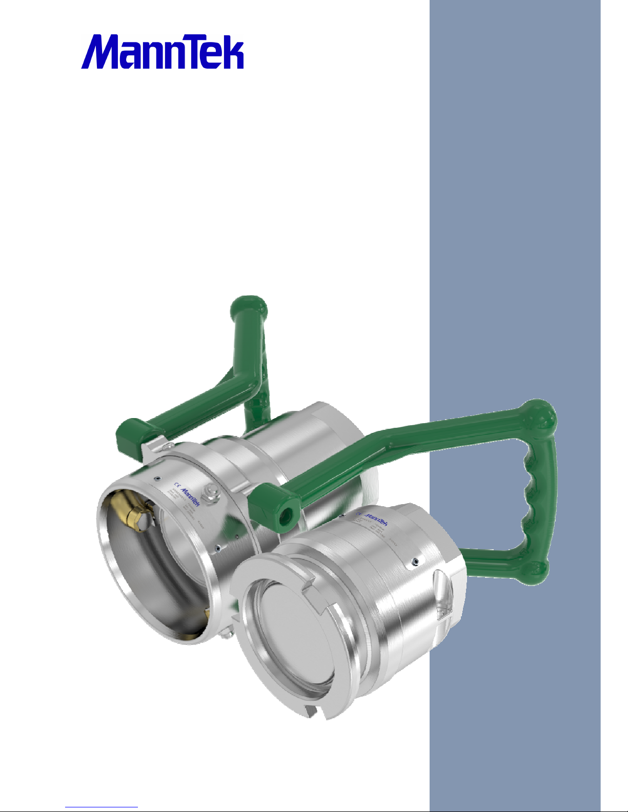
Dry Cryogenic Couplings (DCCs) are designed for use wherever it is necessary to connect and disconnect
hoses and pipelines under moderate pressure, quickly and without spillage. They are designed primarily for
use with cryogenics where reliability and safety are of prime concern.
All MannTek products are designed for trouble free operation in a wide range of applications and operating
conditions. Reliable and safe operation is dependent upon the correct installation and handling of the
equipment. Regular and appropriate maintenance is essential to ensure both safety and reliability over the
life of the equipment. Take care that the product is only used inside the limits of the following product
specification.
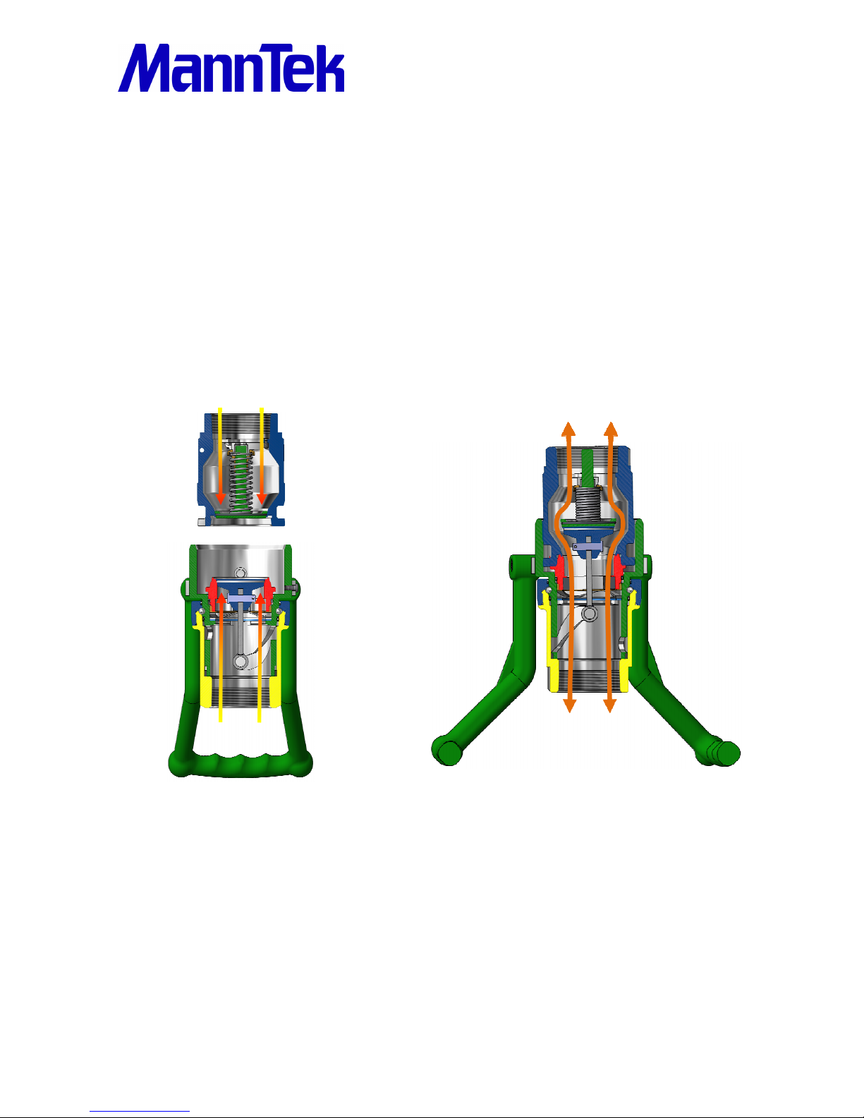
Operation is single action (see chapter 5.4), using a straight forward turning motion to connect the couplings
and open a flow path. An initial push and turn action on the hose unit causes engagement with the tank unit,
thus locking and sealing the two units together. Further rotation causes the internal valves to open, thereby
allowing flow with minimum pressure drop.
The connection and valve mechanism is interlocked such that fully engaging and sealing the hose unit on its
matching tank unit can only open the valve. On disconnection the valve fully close before the coupling
separate and spillage therefore is negligible.
Operating Manual
PR-050823-0121 Version 161109 5 of 14
1.2 P
RODUCT SPECIFICATION
Product name: Dry Cryogenic Coupling
Sizes: 1”, 2“, 2½“, 3“, 4” and 6“
Thread Connection: NPT-Thread ANSI B1.20.1
Flange Connection:
Other Connection:
Flange EN 1092, ANSI B16.5
On request
Material: EN 10272 – 1.4401/1.4404+AT
ASTM A479 – S31603 (316L)
Working pressure and classification according to PED 2014/68/EU:
Pressure accessories:
DDCouplings (STANAG), DGCouplings, DACouplings (ISO45), DCCouplings, SBCouplings and
CBCouplings
Conformity assessment procedure followed:
no CE-marking** SEP=sound engineering praxis Article 4 section 3*
CE 0038 Cat 1=Category 1 Module A
CE 0038 Cat 2=Category 2 Module D1
CE 0038 Cat 3=Category 3 Module G
For piping intended for gases, liquefied gases, gases dissolved under pressure, etc. according to article 4
paragraph 1.(c)(i) [Annex II Table 6]
SS
Weight HU
NPT (6”FL)
Weight TU NPT
(4”+6”FL)
DN25 PN25 SEP* DN25 1,8 kg / 4.0 lbs 0,7 kg / 1.5 lbs
DN40 PN25 Cat 1 DN40 2,8 kg / 6.2 lbs 1,2 kg / 2.6 lbs
DN50 PN25 Cat 2 DN50 2,8 kg / 6.2 lbs 1,2 kg / 2.6 lbs
DN65 PN25 Cat 2 DN65 7,2 kg / 15,9 lbs 3,1 kg / 6.8 lbs
DN80 PN25 Cat 2 DN80 9,3 kg / 20.5 lbs 4,0 kg / 8.8 lbs
DN100 PN25 Cat 2 DN100 14,7 kg / 32.7 lbs 8,7 kg / 19.2 lbs
DN150
PN16 Cat 2
DN150 42,5 kg / 93.7 lbs 20,0 kg / 44.1 lbs PS23.3 bar Cat 2
PN25 Cat 3
*
According to Article 4 section 3, the products designed and manufactured in accordance with the sound
engineering practice (SEP) must not bear the CE marking. Unauthorized product modifications lead to an
invalid declaration.
**Attention: If the coupling is Ex-marked the CE-marking is for ATEX classification
Maximum burst pressure: 125 bar (6” = 80 bar) / 1800 psi (6” = 1160 psi)
Temperature range: -196ºC to +80ºC / -320ºF to +175ºF
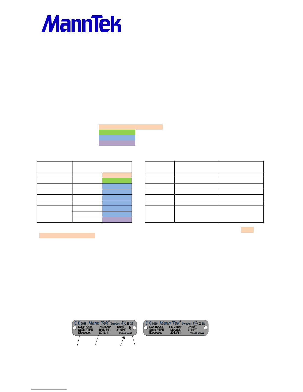
1.3 I
DENTIFICATION PLATE
E.G. FOR
DCC 3”-3”NPT
Hose unit (Coupler) Tank unit (Adapter)
Article no: MC415A44* LC415A44*
Size: 3” – 3” NPT 3“ – 3” NPT
Working Pressure PS: 25 bar 25 bar
Material: Stainless Steel Stainless Steel
Seal: PTFE (Teflon®) PTFE (Teflon®)
PED MAWP ADR/RID ATEX
*For key of article no. please ask for explanation list.
 Loading...