

Page 1
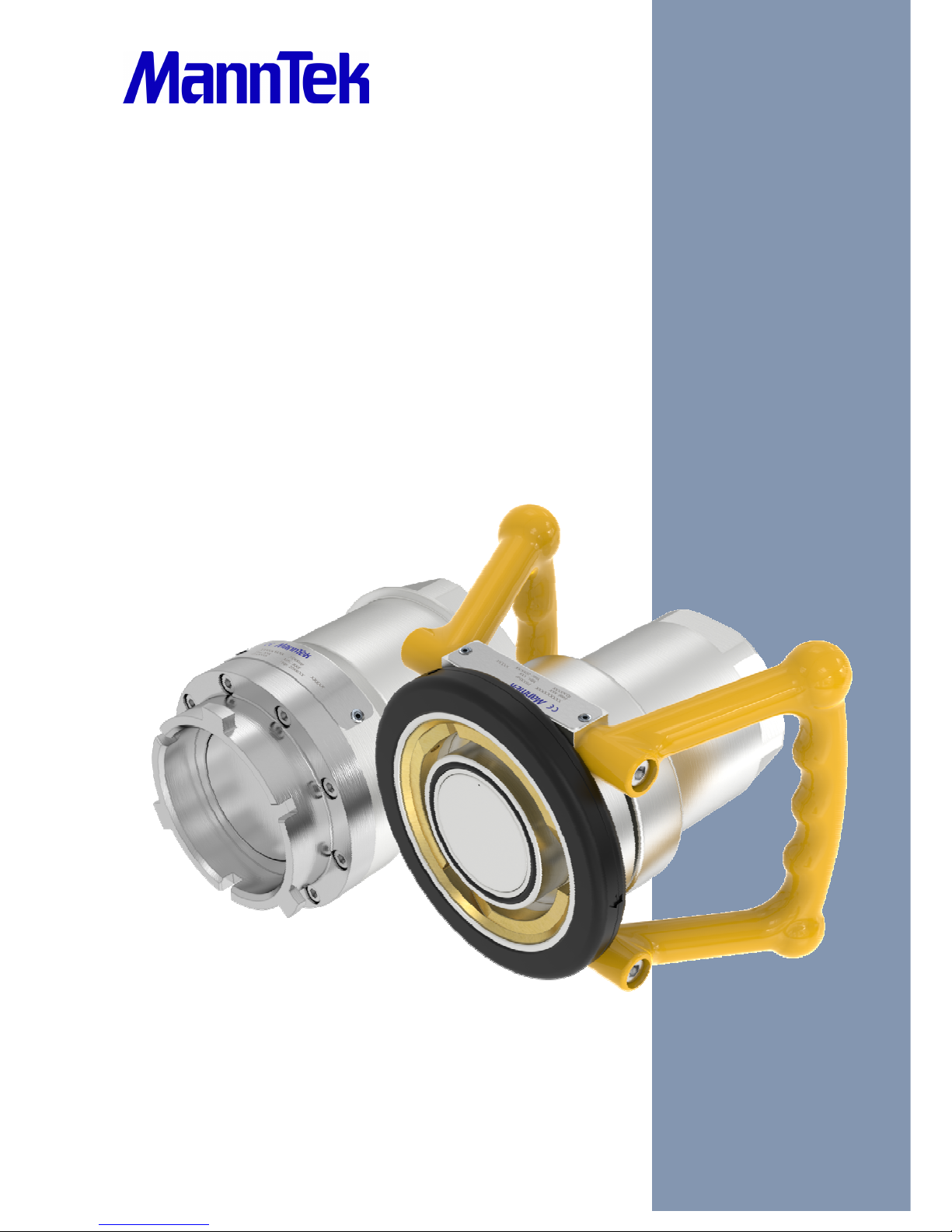
DAC Operating Manual
manntek.se
Page 2

Operating Manual
PR-100601-0121 Version: 081010
2
F
OREWORD
This operating manual applies to the person or persons using the Dry Aviation Couplings.
It is very important to read and understand this operation manual before use of this
coupling. Become familiar with the unit’s operation, applications and limitations. Be
particularly aware of its specific hazards. Store this manual in a clean area and always at a
readily available location. Additional copies at no charge can be obtained through written
requests.
IMPORTANT!!
READ THE COMPLETE DOCUMENTATION
The base for this manual follows the EC-Directive:
Pressure Equipment Directive
2014/68/EU of 15th May 2014
• Do not make modifications that are not authorized by the manufacturer.
• Read and respect all warnings and instructions provided to you.
•
Use only original MannTek spare parts for maintenance.
S
UMMARY OF REVISIONS
Date of change
Description
2004
-02-09
New pressure ratings, Storage
2004
-02-20
Copyright remark
2008
-10-29
New front page layout
2010
-03-08
General review
2016
-09-22
General review & New front page layout
Page 3

Operating Manual
PR-100601-0121 Version: 081010
3
T
ABLE OF CONTENTS
1 Introduction .................................................................................... Fel! Bokmärket är inte definierat.
1.1 Intended use .................................................................................................................................... 4
1.2 Product specification........................................................................................................................ 5
1.3 Identification plate ............................................................................................................................ 5
1.4 Flow diagram / Pressure drop curve ................................................................................................ 5
1.5 Scope of delivery ............................................................................................................................. 6
2 Safety notes ......................................................................................................................................... 6
3 Transport and storage .......................................................................................................................... 6
3.1 Delivery Check ................................................................................................................................. 6
3.2 Complaints / Return of goods .......................................................................................................... 7
3.3 Returning Used Product .................................................................................................................. 7
3.4 Sample of Certificate of Decontamination ....................................................................................... 7
4 Installation ............................................................................................................................................ 8
4.1 Initial operation ................................................................................................................................ 8
4.2 Installation ........................................................................................................................................ 8
5 Operation ............................................................................................................................................. 9
5.1 General notes .................................................................................................................................. 9
5.2 Making connection/disconnection .................................................................................................... 9
5.3 Daily visual inspection ................................................................................................................... 10
5.4 Cleaning ......................................................................................................................................... 11
5.5 Disassembly .................................................................................................................................. 11
5.6 Improper use .................................................................................................................................. 11
5.7 Maintenance / repair ...................................................................................................................... 11
5.8 Miscellaneous ................................................................................................................................ 11
6 Maintenance and repair ..................................................................................................................... 11
6.1 General information ....................................................................................................................... 11
6.2 Assembly ....................................................................................................................................... 12
6.3 Pressure and tightness test ........................................................................................................... 12
7 Applicable documents ........................................................................................................................ 12
Page 4
Operating Manual
PR-100601-0121 Version: 081010
4
1 I
NTRODUCTION
1.1 I
NTENDED USE
Dry Aviation Couplings are designed for use wherever it is necessary to connect and disconnect hoses and
pipelines under pressure, quickly and without spillage. They are designed primarily for use of petroleum and
aviation fuels where reliability and safety are of prime concern.
All MannTek products are designed for trouble free operation in a wide range of applications and operating
conditions. Reliable and safe operation is dependent upon the correct installation and handling of the
equipment. Regular and appropriate maintenance is essential to ensure both safety and reliability over the
life of the equipment. Take care that the product is only used inside the limits of the following product
specification.
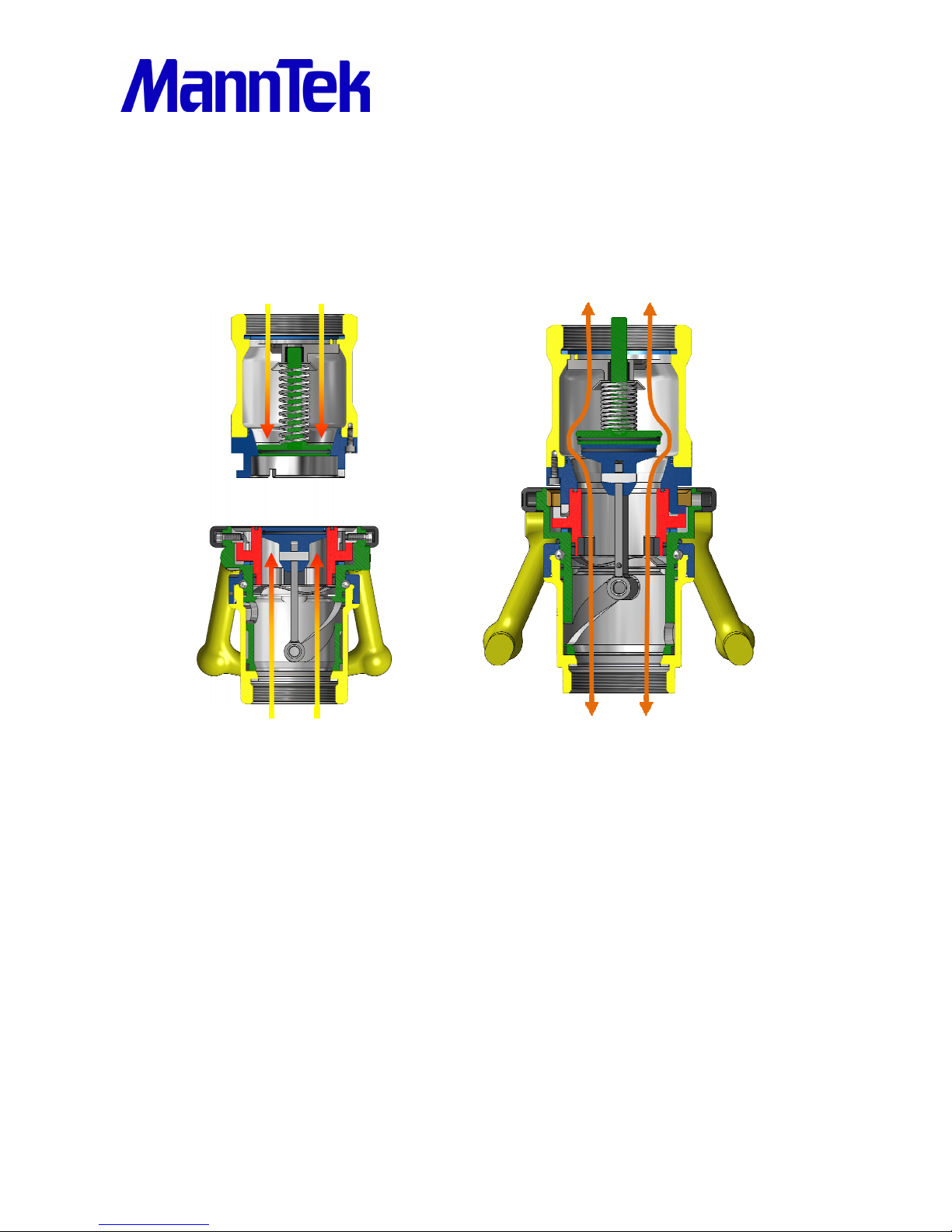
Operation is single action (see also 5.2), using a straightforward turning motion to connect the couplings and
open a flow path. An initial push and turn action on the hose unit causes engagement with the tank unit, thus
locking and sealing the two units together. Further rotation causes the internal valves to open, thereby
allowing flow with minimum pressure drop.
The connection and valve mechanism is interlocked such that fully engaging and sealing the hose unit on its
matching tank unit can only open the valve. On disconnection the valve fully close before the coupling
separate and spillage therefore is negligible.
Page 5
Operating Manual
PR-100601-0121 Version: 081010
5
1.2 P
RODUCT SPECIFICATION
Product name:
Dry Aviation Coupling 2½“ ISO45
Connection: Thread: 2½“ or 3“; BSP or NPT
Flange: EN1092 PN10/16 or ASA B16.5 150 PSI
Diameter: 166 mm / 6 17/32 inch
Width over Handle (max):
254 mm / 10 inch
Length (with BSP): 163 mm / 6 13/32 inch
Material:
EN 1706 AC
-
42100 / ASTM B26
– 356,0
Material flange:
EN 10272
-
1.4404 / ASTM A479
– S31603 (316L)
Working pressure: 10,3 bar / 150 psi
Max test pressure:
15,5 bar / 225 psi
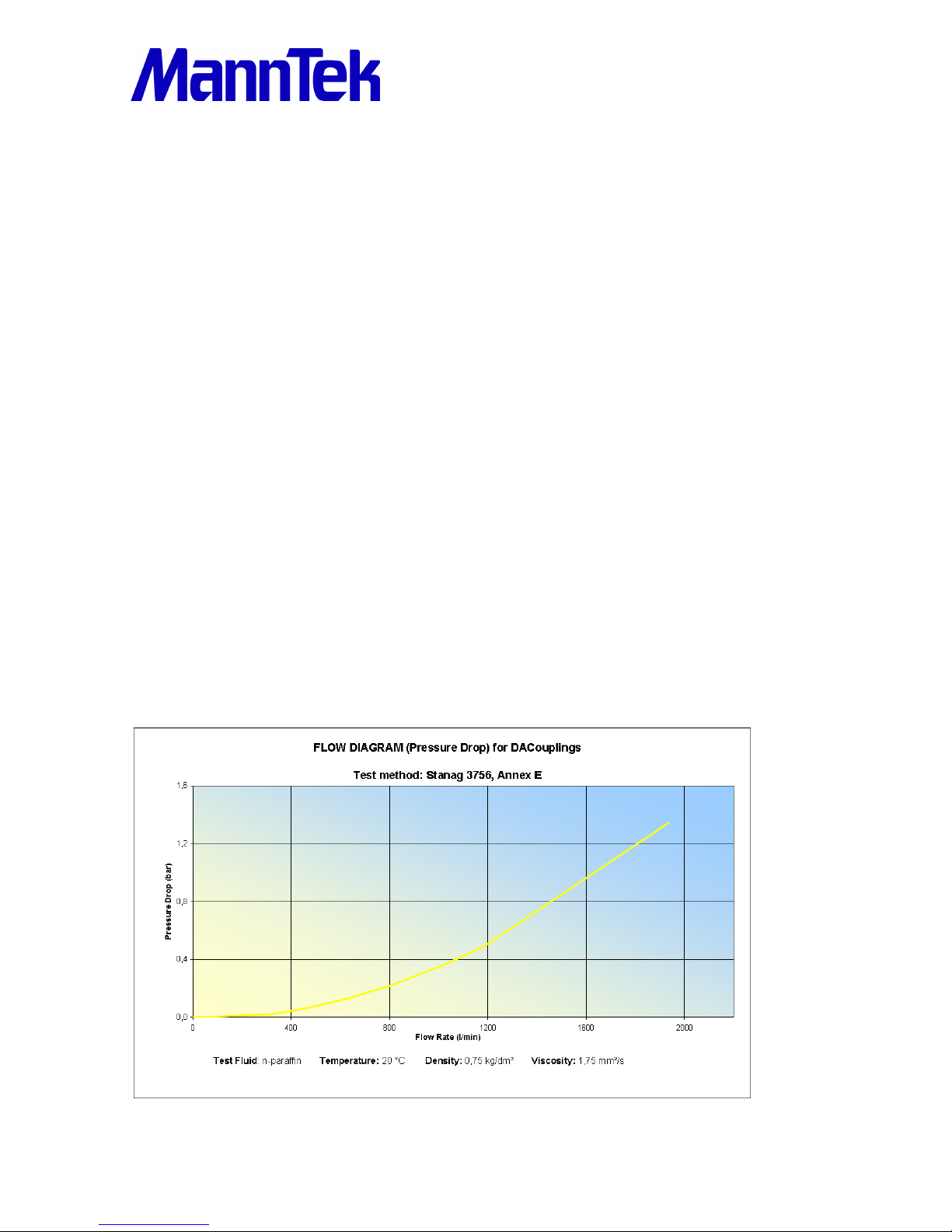
Flow rate: 980 l/min (for up to 2400 l/min see also 4.1)
Temperature range (static):
-54ºC to +80ºC /
-
65.2ºF to +176ºF
Temperature range (operation): -38ºC to +60ºC / -36.4ºF to +140ºF
1.3 I
DENTIFICATION PLATE
Hose unit (Coupler) Tank unit (Adapter)
Article no:
F314B1105
B*
G31
4B1105
B*
Size: 2½“ – 3” BSP 2½“ – 3” BSP
W
orking
P
ressure
: 10 bar
10 bar
Material: Al Al
Seal: NBR-LT, (MFQ) NBR-LT, (MFQ)
*For key of article no. please ask for explanation list.
1.4 F
LOW DIAGRAM / PRESSURE DROP CURVE
Page 6

Operating Manual
PR-100601-0121 Version: 081010
6
1.5 S
COPE OF DELIVERY
1 pcs DACoupling 2½” ISO45 Hose unit 3” BSP
1 pcs DACoupling 2½” ISO45 Tank unit 3” BSP
In case of flange connection gaskets and bolts to mount the coupling into the application is not part of the
delivery. For NPT thread use PTFE tape for sealing.
2 S
AFETY NOTES
Before you install any MannTek equipment it is essential to check that the material and performance
specifications are acceptable for your specific application. The pressure ratings and primary materials of the
construction are clearly indicated on the identification plate of each MannTek product. A drawing showing the
materials of construction relating to each individual component is available upon request. The technical
department at Mann Teknik AB is always happy to provide guidance on material suitability. Our data is taken
from published chemical resistance information as well as our own application experiences. Specification
checks should always be carried out before the product is supplied, but if unsure, ask! Especially if you are
using the products outside the specified temperature range, ask for confirmation regarding your application.
Do not assume that a MannTek product supplied for one specific application automatically will be suitable for
other similar applications. Many variables affect the performance of materials. If you wish to use a MannTek
product for a different application than the one originally specified, check with Mann Teknik AB to ensure
compatibility before installation. Please remember, the application details should include all media
transferred through the coupling. Not just the primary transferred media. As with all equipment, a check
should be made to ensure that the installation fulfils the requirements of applicable prevailing industry, local,
national and international standards. Particular attention should be paid to pressure ratings, safety factors
and the position of upstream and downstream affiliated closures.
3 T
RANSPORT AND STORAGE
The product may only be transported or stored when absolutely clean. Suitable sealing must be used for the
openings to ensure no damage occurs to the surfaces/sealed areas. The seals may only be removed by
trained personnel. The storage location must guarantee adequate protection from corrosion or extreme
temperatures.
3.1 D
ELIVERY CHECK
• Check for any transportation damage. If so report this immediately to the forwarder.
• Check that the products and quantities are in accordance with the delivery note.
Page 7

Operating Manual
PR-100601-0121 Version: 081010
7
3.2 C
OMPLAINTS / RETURN OF GOODS
• If returning goods please contact Mann Teknik AB to receive a Complaint Report form.
• Complete the form with as much details as possible.
• Return the goods with the Complaint Report attached on the outside of the package!
3.3 R
ETURNING USED PRODUCT
• If returning used goods please contact Mann Teknik AB to receive a Complaint Report form.
• Complete the form with as much details as possible.
• Fill in the Certificate of Decontamination. For a sample see 3.4
• Return the goods with the Complaint Report and the Certificate of Decontamination attached on the
outside of the package!
3.4 S
AMPLE OF CERTIFICATE OF DECONTAMINATION
REPAIR SERVICE
To comply with Health & Safety Regulations, all returned valves must be accompanied by a
Certificate of Cleanliness
Certificate of CleanlinessCertificate of Cleanliness
Certificate of Cleanliness and a Data Sheet for the last product carried (even the cleaner).
CERTIFICATE OF DECONTAMINATION
We certify that the following couplings/valves have been cleaned prior to despatch and are
free of any harmful substances:
Quantity:
Part no:
Serial No:
Quantity:
Part no:
Serial No:
Quantity:
Part no:
Serial No:
YES NO
Free of all liquid _____ _____
Air blown _____ _____
Couplings/Valve dismantled _____ _____
Data sheet of last product attached _____ _____
The last known product the coupling/valve was in contact with:
Media Cast Number:
Company Name/Address (Stamp): Signature of Supervisor:
Page 8

Operating Manual
PR-100601-0121 Version: 081010
8
4 I
NSTALLATION
4.1 I
NITIAL OPERATION
The correct installation of all MannTek products is essential to ensure safe and satisfactory operation.
Checks should be made to ensure that the fitting of MannTek products does not interfere with the correct
operation of affiliated equipment (i.e. isolation valve, excess flow valves, etc). Before securing the flange or
thread connection to mating equipment (i.e. hose, loading arm, and storage tank) ensure that no foreign
objects, dirt, grit, etc. are present in the coupling.
All flange and thread connections should be made without imparting excessive strain to the equipment and
pressure checked at least to 1.5 times the maximum application working pressure prior to use. All gaskets
and sealing materials used to make the permanent connection should be of suitable material and able to
operate at least up to the maximum parameters of the MannTek equipment.
Each MannTek product is designed to take reasonable axial loads associated with good handling practice
but is not designed to accept continuous excessive load values associated with maladjustment or poor
installation. Continuous excessive strain will equate to increased component wear and possibly premature
failure if not corrected.
When MannTek equipment is used with hoses, attention should be paid to hose length to ensure correct
handling characteristics. The hose assembly should be designed such that the minimum hose length is
supported by the coupling or the operator. Hoses should be of sufficient length to ensure operation well
within the stipulated hose minimum bend radius up to the maximum operation envelope. If the flow velocity
exceeds 5.25 m/s additional measures are necessary due to static electricity. This could be hoses with
increased conductivity, charge inhibiting additives, earth bonding.
Once all the above elements are satisfactory, a function check should be carried out to prove the system.
The hose unit or coupler should connect and disconnect without physical interference or difficulty. Please
remember that the higher the static pressure, the greater the effort to make a connection. The MannTek
technical department is happy to advice on this subject at the specification stage.
4.2 I
NSTALLATION
When installing MannTek equipment to new pipe work, tanks, etc. ensure the system is free from debris that
may be transferred through the coupling. Where the hose or loading arm assembly is the primary static
dissipation or earth route, the electrical continuity value of the assembly shall be checked to ensure
regulatory compliance. Special attention should be paid to the balancing of loading arms. The weight of the
coupling plus transfer media should be taken into account at the specification stage. It is usual for loading
arm balance settings to account of weight variations due to differences in the full / empty cycle. The loading
Page 9

Operating Manual
PR-100601-0121 Version: 081010
9
arm should be set to balance in the condition present at the time or connection. For example, should the
loading arm be empty at the time of connection then it should be balanced in the empty condition.
The MannTek product can be installed directly in the product line and is ready for use after removing the
transport protection. The installation is as follows:
a. Remove the packaging and the tread/flange protection
b. Check the coupling for damages before mounting.
c. To prevent damages during mounting a suitable wrench should be used for the intended nut flats on the coupling
(threaded connection) or the bolts (flanged connection).
d. Ensure that the product line is empty and all valves are closed before you connect the coupling into the line.
The start-up may take place only when the MannTek product has been mounted as instructed and the
necessary function tests and leak tests have been conducted by the approved authorities.
5 O
PERATION
5.1 G
ENERAL NOTES
Operators are obliged to provide qualified and trained personnel familiar with the handling of supply pipes,
safety couplings, any fluid being pumped as well as its danger potential. Such staff must also be familiar with
the applicable safety regulations and the regulations of the employer’s liability association.
When making the connection, make sure that all relevant isolation valves connected in the
hose unit application are closed. Also check that no pumping pressure is present at the hose
unit. Make sure that all isolation valves behind the tank unit in the pipe work are fully open.
5.2 M
AKING CONNECTION/DISCONNECTION
a. Lift the hose unit and hose into position to start the connection. Take care to support the hose end
assembly so as to present the hose unit to the tank unit in the correct orientation. It is important to
ensure the hose unit is not supporting the full weight of the hose assembly during the connection
process. Loading should be balanced to a neutral condition in the connection phase. Once connected,
the hose unit is secure to the tank unit and able to accommodate all reasonable axial strain. The
handles have no operating purpose other than providing handling assistance.
b. When correctly supported, the hose unit should slide easily over the tank unit. The three tappets on the
tank unit engage in the three slots in any one of three positions at 120 degree centre. Rotate the hose
unit clockwise about 100 degrees whilst gently pushing towards the tank unit. At the start of rotation you
will feel some resistance. The level of resistance is dependent upon the static line and tank pressure.
Page 10

Operating Manual
PR-100601-0121 Version: 081010
10
The higher the pressure the greater the effort necessary to connect the coupling. At the completion of
the 100 degree turn you will feel a definite stop. Do not attempt to rotate the unit further. Further rotation
does not tighten the connection or open the valves more, it only causes unnecessary damage. The
hose unit valve is now open and the loading process can start.
c. The sequence of isolation valve and/or pump operation should be taken from your operating
procedures; however it is preferable for the vehicle isolation valve to be the last valve opening in the
sequence. This reduces the possible surge effect on the coupling seals often associated with
automatically actuated valve systems.
d. The disconnection procedure is similar to the connection procedure but in reverse. Before any attempt
is made to disconnect the coupling, all isolation valves should be closed and where possible, the pumps
be switched off. Where a common pumping system is in use, all flow through the coupling shall be
stopped using the isolation valves and not the coupling. Closing the vehicle isolation valve first is
preferred according to reasons in section (c) so long as this is compatible with your standard operating
procedures.
e. Whilst supporting the hose unit assembly, turn the hose unit anti-clockwise approximately 100 degrees.
You may feel a slight ”pop off” effect at the end of the rotation travel when transferring liquids with an
elevated vapour pressure. This is normal. Do not attempt to rotate the hose unit further. This will not
further loosen the connection or secure the seal, it only causes unnecessary damage.
f. The hose assembly should be stowed in a manner so as to avoid physical damage. Do not drop the
hose end assembly or stow on the floor. The dust plug provided should always be fitted. Ensure the
tank unit cap (if fitted) is replaced and secured.
5.3 D
AILY VISUAL INSPECTION
All couplings should be briefly inspected at the start of each day’s operation.
a. Inspect the coupling surface for cleanliness and corrosion. Check for dirt and any obvious physical
damage (such as impacts, etc.).
b. Inspect the O-ring in the hose unit connection for serviceability and correct seating in the groove.
c. Inspect the hose unit swivel for free rotation.
d. Inspect the tank- and hose unit for faultlessness and external signs of seizure.
e. On the first operation, check for leakage and smooth operation.
Page 11

Operating Manual
PR-100601-0121 Version: 081010
11
5.4 C
LEANING
Check the seal of the connections before every cleaning. In case the coupling is used for materials that
harden, stick, etc., the coupling has to be cleaned of residues after every use. Before dismantling, the
coupling always has to be cleaned with a suitable cleaning agent (regardless of the product carried).
5.5 D
ISASSEMBLY
When the DACoupling should go into service there is a danger that the fluid will spurt out. Special protective
measures such as personal protection equipment must therefore be adopted. Always ensure that the system
is cleaned in the proper manner. After cleaning, remove any residue from the cleaning agent.
How to disassemble:
a. Wear suitable personal safety equipment.
b. Make sure that the coupling is depressurized and empty.
c. Clean coupling before disassembly (use cleaning agent suitable for the pumped fluid).
d. Unscrew coupling (threaded connection) or bolts (flanged connection) with a fitting
wrench.
5.6 I
MPROPER USE
The equipment should never be used in the case of visible damage or where there is prior knowledge of
damage that may lead to malfunction.
5.7 M
AINTENANCE / REPAIR
Maintenance should be done regularly. Maintenance on hose units may follow the recommendation for the
hoses, on tank units it is sufficient to follow the service interval of the tank truck or dispenser vehicles.
Maintenance and repair of the equipment may be carried out only by Mann Teknik AB or by companies/
technicians authorized by Mann Teknik AB (see paragraph 6).
5.8 M
ISCELLANEOUS
The operator is solely responsible for the installation, operation and maintenance of the coupling. Mann
Teknik AB accepts no responsibility for damages due to faulty installation, faulty handling, as well as
negligent or incorrect maintenance.
6 M
AINTENANCE AND REPAIR
6.1 G
ENERAL INFORMATION
Maintenance tasks may be performed only by trained personnel from an authorised professional workshop.
All measures necessary for inspection, maintenance and repair must be carried out in accordance with the
national regulations of the country where the system is installed. A separate service instruction is available
on request.
Page 12
Operating Manual
PR-100601-0121 Version: 081010
12
6.2 A
SSEMBLY
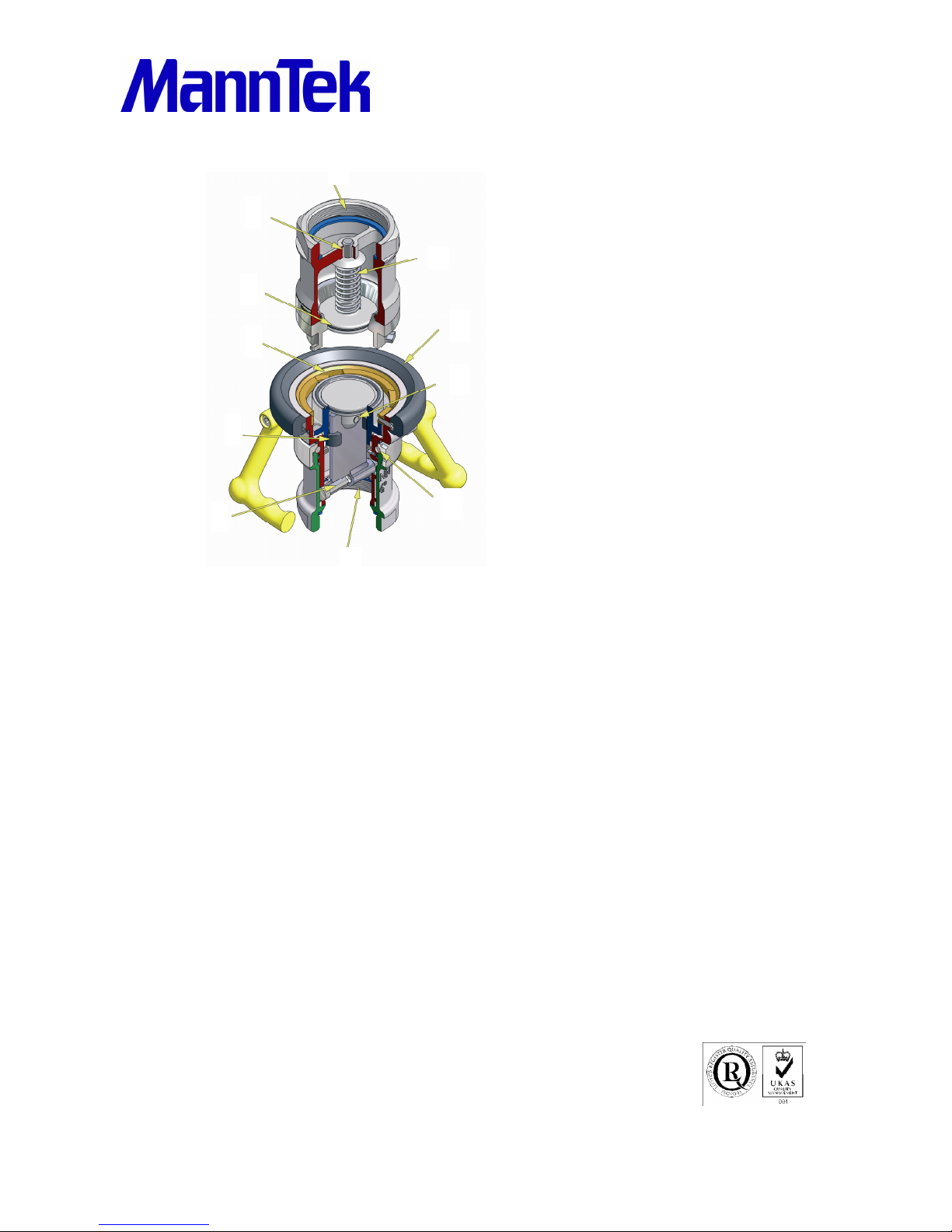
Positioning DACoupling
1 Tank unit body
2 Piston guide
3 Piston
4 Spring
5 Hose unit body
6 Couplingsring
7 Piston with riveted pin
8 PTFE bearing
9 Piston guide with rollers
10 Ball bearing for swivel joint
11 Protective ring
The balls are greased with low
temperature synthetic grease.
6.3 P
RESSURE AND TIGHTNESS TEST
After each service a pressure and tightness test is mandatory. The following test parameters are in
accordance with EN12266 and EN14432:
• Shell strength test: 15 bar stop time 1 min.
•
Shell tightness test: 0,2 bar stop time 1 min.
6 bar +/- 1bar air stop time 1 min.
7 A
PPLICABLE DOCUMENTS
PED 2014/68/EU, 208/68/EC (ADR), ISO 45, STANAG 3105
Material standards EN 1706, EN 10272,
ASTM B 26, ASTM A 479
Test standards EN12266, EN14432
Flange standard EN1092, ANSI B16.5, DIN 28459, T.T.M.A
For use in other countries:
Respective national requirements and guidelines
Mann Teknik AB
Strandvägen 16, S-54231 Mariestad, Sweden
Phone +46 501 393200 • Fax +46 501 393209
www.mann-tek.se • [email protected]
Mann Tek is a certified ISO9001-company.
2
3
1
11
7
4
10
5
6
8
9
 Loading...