

Page 1
Operating and
Instruction Manual
Manual No. YB
Revision 0-600 w/12 March 2014 Errata
MODEL YB8
STATIONARY
PERISTALTIC SAMPLERS
Manning Environmental, Inc.
101 Bar T Drive
Florence, Texas 76527-4445 USA
Office: (800) 863-9337
(254) 793-9955
Fax: (254) 793-9965
www.manningenvironmental.com
Page 2

Page 3

Manning Environmental Limited Factory Warranty
Manning Environmental, Inc., warrants this product to the original purchaser against any defects that are
due to faulty workmanship or material for a period of one year (365 days) from the date of shipment.
During the warranty period Manning Environmental, Inc. will repair or replace, at its sole discretion, any
defective equipment or parts. Manning’s liability is strictly limited to repair and/or replacement. Any
product repaired or replaced under this warranty will be warranted only for the remainder of the original
product warranty period.
This warranty does not apply to consumable products or consumable components of products such as,
but not limited to tubing, intake hose, differential pressure switches and bottles.
Items may not be returned without authorization from Manning Environmental, Inc.
This warranty applies only to products sold under the Manning trademark and is the sole express
warranty made by Manning Environmental, Inc. All implied warranties, including without limitation, the
warranties of merchantability or fitness for a particular purpose, are disclaimed.∗
Limitations:
This warranty does not cover the following:
1. Damage caused by acts of God, natural disaster, labor unrest, acts of war (declared or
undeclared), terrorism, civil strife or acts of any governmental jurisdiction
2. Damage caused by normal wear, neglect, misuse, accident, corrosion or improper application or
installation
3. Damage caused by any repair, attempted repair or modifications not authorized by Manning
Environmental, Inc.
4. Any product not used in accordance with the instructions furnished by Manning Environmental,
Inc.
5. Freight charges to return merchandise to Manning Environmental, Inc.
6. Freight charges on expedited or express shipment of warranted parts or products.
7. Travel and lodging fees associated with on-site warranty repair
8. Manning 6.1 cubic foot refrigerators, which are covered under the refrigerator manufacturer’s
warranty
9. Labor performed at the factory to clean the equipment so that it can be safely and properly
repaired
This warranty constitutes the final, complete, and exclusive statement of warranty terms. Manning
Environmental, Inc. does not authorize any other person to make any other warranties or representations
on its behalf.
In no event shall Manning Environmental, Inc. be liable for any incidental or consequential damages of
any kind for breach of warranty or negligence. The remedies of repair or replacement as stated above
are the exclusive remedies for the breach of this warranty.
A Return Material Authorization (RMA) must be obtained prior to sending any equipment to Manning for
warranty service. Contact the Manning Service Department at:
Manning Environmental, Inc.
101 Bar T Drive
Florence, Texas 76527-4445
Phone: 254-793-9955, Fax: 252-793-9965.
Some states within the United States do not allow the disclaimer of implied warranties and if this is true in your state the above
∗
limitation may not apply to you. This warranty gives you specific rights- you may also have other rights that vary from state to state.
Manning Environmental, Inc. December 2005
Page 4

Page 5

Table Of Contents
Section Contents – Installation and Ope ration
Introduction ...........................................................................................................................................Page A-1
Hardware Page ......................................................................................................................................Page A-2
Functional Specifications ..........................................................................................................Page A-2
Size ................................................................................................................................Page A-2
Weight ...........................................................................................................................Page A-2
Environmental Protection ............................................................................................ Page A-2
Sample Cooling ............................................................................................................Page A-2
Temperature Limits .......................................................................................................Page A-2
Sample Pump ................................................................................................................Page A-2
Safety ............................................................................................................................Page A-2
Pump Tubing .................................................................................................................Page A-2
Tube Life .......................................................................................................................Page A-2
Maximum Lift ...............................................................................................................Page A-2
Transport Velocity ........................................................................................................Page A-2
Sample Volume .............................................................................................................Page A-2
Accuracy .......................................................................................................................Page A-2
Repeatability .................................................................................................................Page A-2
Liquid Sensor ................................................................................................................P age A-2
Controller ......................................................................................................................Page A-3
Electronics.....................................................................................................................Page A-3
Internal Clock................................................................................................................Page A-3
Internal Battery .............................................................................................................Page A-3
Power ............................................................................................................................Page A-3
Battery Back-Up ...........................................................................................................Page A-3
Analog Input .................................................................................................................Page A-3
Subassemblies ...........................................................................................................................Page A-3
Electronics Enclosure....................................................................................................Page A-3
The Controller ...................................................................................................Page A-3
Peristaltic Pump ............................................................................................................Page A-4
Liquid Sensor ................................................................................................................P age A-5
Refrigerator ...................................................................................................................Page A-5
Wetted Parts ..................................................................................................................Page A-5
Intake Hose .......................................................................................................Page A-5
Strainer ..............................................................................................................Page A-5
Pump Tubing .....................................................................................................Page A-6
Discharge Tubing ..............................................................................................Page A-6
Bottle Full Sensor .............................................................................................Page A-6
Sample Bottles ..................................................................................................Page A-7
Assembly...................................................................................................................................Page A-8
Page 6

Assembling the Model YB8 Sampler ...........................................................................P age A-8
Refrigerator .......................................................................................................Page A-8
Electronics Enclosure........................................................................................Page A-9
Distribution Assembly Installation .............................................................................Page A-10
Single Bottle Sampling ...................................................................................Page A-10
Multiple Bottle Sampling ................................................................................Page A-10
Suspension Plate Installation ..............................................................Page A-10
Distributor Assembly ..........................................................................Page A-10
Bottle Installation ............................................................................................Page A-13
One Liter and Half-Liter Plastic Bottles Page A-13
Spout Position Page A-13
Installing The Sampler ............................................................................................................Page A-13
Connecting Power .......................................................................................................Page A-14
Sample Intake Line .....................................................................................................Page A-14
Intake Hose Placement ................................................................................................P age A-14
Running a Test Cycle ..............................................................................................................Page A-15
The Sampling Cycle ................................................................................................................Page A-15
Sample Recovery ....................................................................................................................Page A-16
External Connections ..............................................................................................................Page A-17
Contact In & Analog In Connections..........................................................................Page A-17
Bottle Full Sensor & Stepper Motor Connections ......................................................P age A-17
Bottle Full/Stepper Motor ...............................................................................Page A-17
Contact Closure ...............................................................................................Page A-18
Analog Signal (Optional) ................................................................................Page A-18
Section Contents – Programming
Introduction ........................................................................................................................................... Page B-1
Sampler Configuration .......................................................................................................................... Page B-1
Sampling Modes ................................................................................................................................... Page B-1
Multi-Bottle Sampling Modes .................................................................................................. Page B-1
Single Bottle Modes .................................................................................................................. Page B-1
<RESET> .................................................................................................................................. Page B-2
<TEST CYCLE> ...................................................................................................................... Page B-2
<BOTTLE ADV> ..................................................................................................................... Page B-2
<CLEAR> ................................................................................................................................. Page B-2
<CLOCK> ................................................................................................................................ Page B-2
<DISPLAY> ............................................................................................................................. Page B-2
*................................................................................................................................................. Page B-2
EEEE ......................................................................................................................................... Page B-2
Key Not Active ......................................................................................................................... Page B-2
Display Information .............................................................................................................................. Page B-3
Time of Day .............................................................................................................................. Page B-3
Program Status .......................................................................................................................... Page B-3
Sampler Ready .............................................................................................................. Page B-3
Page 7

Programming................................................................................................................. P age B-3
Active Program ............................................................................................................. Page B-3
Sampler Configuration Functions ......................................................................................................... Page B-4
*99 Sampler Set-Up .................................................................................................................. Page B-4
*20 Volume Calibration ............................................................................................................ Page B-7
*19 Pump Utilities .................................................................................................................... Page B-9
*91 Data Logging ................................................................................................................... P age B-11
ID Menu ...................................................................................................................... Page B-12
View Menu.................................................................................................................. Page B-12
Exit Menu.................................................................................................................... Page B-16
Download Menu.......................................................................................................... Page B-16
Clear Menu.................................................................................................................. Page B-18
*14 Clear Log Data ..................................................................................................... Page B-18
Analog Option Programming .............................................................................................................. Page B-19
Totalizing ................................................................................................................................ Page B-19
*08 Analog Display Routine ....................................................................................... Page B-20
Add-On Programming Functions ........................................................................................................ P age B-22
Multiple Bottles per Sampling Event ...................................................................................... Page B-22
Multiple Samples per Bottle ................................................................................................... Page B-22
Delay Start - Time ................................................................................................................... Page B-24
*15 - Active Sampling ........................................................................................................Page B-24-A
General Programs................................................................................................................................ Page B-25
Time Mode - *START ............................................................................................................ Page B-25
Time Mode - Single Time Interval ......................................................................................... Page B-26
Flow Mode .............................................................................................................................. Page B-28
Flow Mode - Pulse Accumulation .......................................................................................... P age B-29
Multi-Bottle Sampling Programs ........................................................................................................ Page B-30
*01 Flow Mode - Independently Time Spout Advance .......................................................... Page B-30
*02 Flow Mode - Time Interval Override............................................................................... Page B-31
*03 Flow Mode - External Event ............................................................................................ Page B-32
*04 Time Mode - Multiple Intervals ....................................................................................... Page B-33
*07 Flow Mode - Time Delay Interval ................................................................................... Page B-35
Analog Sampling Programs ................................................................................................................ Page B-36
*05 Flow Mode - Totalizing Analog ...................................................................................... Page B-36
*06 Analog Level Mode ......................................................................................................... Page B-38
*09 Hydrologic Level Event Mode ......................................................................................... Page B-41
Multi-Bottle Flow Composite Programs ............................................................................................. Page B-45
*10 Flow Mode - Multiple Bottle Composite ......................................................................... Page B-45
*11 Flow Mode - Totalizing Analog Multiple Bottle Composite........................................... P age B-47
*12 Flow Mode - Multiple Bottle Composite with Bottle Groups ......................................... Page B-49
*13 Flow Mode- Totalizing Analog Multiple Bottle Composite with Bottle
Groups ..................................................................................................................................... Page B-52
Page 8

Section Contents – Maintenance
Maintenance .......................................................................................................................................... Page C-1
Suggested Maintenance Schedule ............................................................................................. Page C-1
Peristaltic Pump ........................................................................................................................ Page C-2
Replacement of Pump Tubing ...................................................................................... Page C-3
Cleaning the Control Panel and Electronics Enclosure ............................................................ Page C-6
Cleaning the Wetted Parts ......................................................................................................... Page C-6
Intake Hose ................................................................................................................... Page C-7
Liquid Sensor ................................................................................................................ Page C-7
Bottle Full Sensor (Single Bottle Units Only) .............................................................. Page C-8
Spout (Multiple Bottle Units Only) .............................................................................. Page C-8
Sample Containers ........................................................................................................ Page C-8
Refrigerator ................................................................................................................... Page C-8
Environmental Protection ....................................................................................................... Page C-10
Removing and Replacing the Controller................................................................................. Page C-10
Troubleshooting .................................................................................................................................. Page C-11
System Non-Responsive ......................................................................................................... Page C-11
Works Inconsistently .............................................................................................................. Page C-11
Weak Draw ............................................................................................................................. Page C-11
Pump Operates but no Fluid ................................................................................................... Page C-12
Pump Rotor Does Not Rotate ................................................................................................. Page C-12
Purges Constantly ...................................................................................................................Page G-12
Low Sample Volume .............................................................................................................. Page C-12
Excessive Sample Volume ...................................................................................................... Page C-12
Controller Does not Respond to Command ............................................................................ Page C-12
Keypad Inoperative ................................................................................................................. Page C-12
*99 Self Test Indicates Error .................................................................................................. Page C-12
Section Contents - Appendices
Glossary
Appendix A ...............................................................................................................................Page D-1
How to Return Equipment ............................................................................................P age D-1
Address for Repairs.......................................................................................................P age D-1
Parts List
Errata
Page 9

MODEL YB8 INSTALLATION AND OPERATION
Installation and Operation
Section Contents
Introduction ...........................................................................................................................................Page A-1
Hardware Page ......................................................................................................................................Page A-2
Functional Specifications ..........................................................................................................Page A-2
Size ................................................................................................................................Page A-2
Weight ...........................................................................................................................Page A-2
Environmental Protection ............................................................................................ Page A-2
Sample Cooling ............................................................................................................Page A-2
Temperature Limits .......................................................................................................Page A-2
Sample Pump ................................................................................................................Page A-2
Safety ............................................................................................................................Page A-2
Pump Tubing .................................................................................................................Page A-2
Tube Life .......................................................................................................................Page A-2
Maximum Lift ...............................................................................................................Page A-2
Transport Velocity ........................................................................................................Page A-2
Sample Volume .............................................................................................................Page A-2
Accuracy .......................................................................................................................Page A-2
Repeatability .................................................................................................................Page A-2
Liquid Sensor ................................................................................................................P age A-2
Controller ......................................................................................................................Page A-3
Electronics.....................................................................................................................Page A-3
Internal Clock................................................................................................................Page A-3
Internal Battery .............................................................................................................Page A-3
Power ............................................................................................................................Page A-3
Battery Back-Up ...........................................................................................................Page A-3
Analog Input .................................................................................................................Page A-3
Subassemblies ...........................................................................................................................Page A-3
Electronics Enclosure....................................................................................................Page A-3
The Controller ...................................................................................................Page A-3
Peristaltic Pump ............................................................................................................Page A-4
Liquid Sensor ................................................................................................................P age A-5
Refrigerator ...................................................................................................................Page A-5
Wetted Parts ..................................................................................................................Page A-5
Intake Hose .......................................................................................................Page A-5
Strainer ..............................................................................................................Page A-5
Pump Tubing .....................................................................................................Page A-6
Discharge Tubing ..............................................................................................Page A-6
Bottle Full Sensor .............................................................................................Page A-6
Sample Bottles ..................................................................................................Page A-7
April 1999/Manning Environmental Inc.
Page 10

MODEL YB8 INSTALLATION AND OPERATION
Assembly...................................................................................................................................Page A-8
Assembling the Model YB8 Sampler ...........................................................................P age A-8
Refrigerator .......................................................................................................Page A-8
Electronics Enclosure........................................................................................Page A-9
Distribution Assembly Installation .............................................................................Page A-10
Single Bottle Sampling ...................................................................................Page A-10
Multiple Bottle Sampling ................................................................................Page A-10
Suspension Plate Installation ..............................................................Page A-10
Distributor Assembly ..........................................................................Page A-10
Bottle Installation ............................................................................................Page A-13
One Liter and Half-Liter Plastic Bottles Page A-13
Spout Position Page A-13
Installing The Sampler ............................................................................................................Page A-13
Connecting Power .......................................................................................................Page A-14
Sample Intake Line .....................................................................................................Page A-14
Intake Hose Placement ................................................................................................Page A-14
Running a Test Cycle ..............................................................................................................Page A-15
The Sampling Cycle ................................................................................................................Page A-15
Sample Recovery ....................................................................................................................Page A-16
External Connections ..............................................................................................................Page A-17
Contact In & Analog In Connections..........................................................................Page A-17
Bottle Full Sensor & Stepper Motor Connections ......................................................Page A-17
Bottle Full/Stepper Motor ...............................................................................Page A-17
Contact Closure ...............................................................................................Page A-18
Analog Signal (Optional) ................................................................................Page A-18
April 1999/Manning Environmental Inc.
Page 11

MODEL YB8 INSTALLATION AND OPERATION
Introduction
Congratulations on the purchase of a Manning Environmental, Inc. Model YB8 Sampler. The model
selected is the latest in a long line of state of the art equipment produced for over twenty three years by
Manning Environmental Inc. Based on this experience, if there is one thing Manning can claim it is that we
know samplers. T here are Manning samplers still used in regular service today that are over twenty years
old. I t is almost impossible to find an organization with the commitment of producing equipment with such a
history of reliability, dependability, quality and value as exhibit ed by Manning samplers. E ven so,
improvement is a never ending goal at Manning. We are always interested in the perceptions and experiences
of our users. If there are any suggestions or comments on our equipment, this manual, or anything Manning
does, please feel free to contact us.
The YB8 is a stationary peristaltic pump based model which can automatically collect and hold Non-Toxic,
Toxic, and Suspended Solid samples from a liquid source. The unit was designed from the ground up with
active user participation to ensure the features and options that are important to field use were incorporated
into the unit. It employs a high speed, peristaltic pump to draw the samples and an industrial grade
refrigeration unit to cool and maintain them at the EPA recommended 4 C. Backed by Manning’s reputation
for quality and dependability, it will provide years of reliable service.
0
Even if the sampler will not be used immediately upon receipt, unpack and examine it. This will help to
familiarize the user with the equipment. Verify that all of the parts have been received and that no damage
has occurred in shipment . I f damage is noticed, immediately report the extent of it to both the t ransportation
company and to Manning Environmental Inc. In addition, check the packing list to verify that it matches the
items sent and that all accessories ordered are included with the shipment. Manning strives for 100 percent
accuracy in the delivery of our equipment, but even with the most stringent quality assurance, mistakes do
occur. O missions, damage, or mistakes must be reported to Manning Environmental Inc. within 10 working
days of receipt of the shipment.
This manual is designed to communicate a complete understanding of the equipment, its operation,
maintenance, and functions. Manning recommends this manual and the equipment be examined completely
before placing the unit into service. M anning’s commitment to producing reliable, top quality products is
legendary, but the possibilit y of breakdown or malfunction always exists. T his manual should enable the
diagnosis and solving of many potential problems. If the problem cannot be solved, please feel free to call
our service department at 1-800-863-9337 to obtain help. Our first priority is making sure the experience
with Manning equipment is an excellent one. In almost all instances the difficulty can be addressed over the
phone, but in the rare instance it cannot, the equipment may need to be sent back to Manning for service.
Please contact our customer service department at 1-800-863-9337 to obtain a Return Authorization
Number. T hen follow the shipping instructions that will be given. P lease note the malfunction on the paper
work so a diagnosis and a solution to the problem can be arrived at with the least amount of delay.
We recommend the following steps before attempting to use the sampler:
1. Review this manual. Read the errata sheets at the end of this manual for the latest updates.
2. Follow the instructions beginning on page 1-8 to assemble the YB8.
3. Set the time and activate a test cycle.
April 1999/Manning Environmental Inc.
Page A-1
Page 12
INSTALLATION AND OPERATION MODEL YB8
4. Program the YB8.
Hardware
Functional Specifications:
Size Control Unit: 10.75" (27.305cm)W x 7" (17.78cm)H x 9.75" (24.765cm)D
Refrigeration Unit: 23.875" (60.65cm)W x 34.5" (87.63cm)H x 24" (60.96cm)D
Total Unit: 23.875" (60.65cm)W x 41.5" (105.41cm)H x 24" (60.96cm)D
Weight Dry Weight: 110 lb (49.89 kg) with refrigerator.
Environmental Nema 4X, 6 housing around electromechanical components.
Protection
Sample Cooling Industrial Grade refrigeration unit.
Temperature 0°C to 50°C (32°F to 122°F) without optional enclosure and heater.
Limits
Sample Pump High Speed peristaltic, dual roller design with impact and corrosion resistant Delrin
plastic pump body.
Safety Integral safety kill switch. E nsures when the clear plastic face plate is removed from
the pump, it prevents accidental powered rotation.
Pump Tubing 3/8" ID by 5/8" OD by 1/8" thick medical grade silicone rubber pump tubing.
Tube Life Recommended maximum of 1,000,000 pump revolutions based on a standard sample.
A standard sample equates to 5ft of head, 10 foot PVC intake tube, and 200 ml sample
size.
Maximum Lift 28 ft (8.5344 m).
Transport Minimum of 3 ft/s at 3 ft of lift (0.9144 m/s at 1 m) and 2.0 ft/s at 20 ft of lift (0.6096
Velocity m/s at 6.1 m).
Sample Volume Programmed directly in increments of 1 milliliter up to a maximum of 9,999 ml.
Accuracy ± 10ml or ± 10% of the programmed volume, whichever is greater.
Repeatability ± 5ml or ± 5% of the average largest and smallest sample volume in a sample set,
whichever is greater.
®
Liquid Sensor Continuity type or Ultrasonic (optional)
Page A-2
April 1999/Manning Environmental Inc.
Page 13
MODEL YB8 INSTALLATION AND OPERATION
Controller Microprocessor based 1 board system which controls all functions of the unit.
Membrane Ergonomically designed, hermetically Sealed, 24 key, multiple function, with 2 line by
Switch 20 character alphanumeric backlighted display.
Electronics 100% Solid State.
Internal Clock Indicates real time with ± 1min/month accuracy.
Internal Battery 5 year internal lithium battery to maintain program logic, RAM memory, real time
clock and date.
Power 115 volt AC, 60 Hz. - Standard
220 volt AC, 50 Hz . - Optional
Battery Back-Up Optional 12 VDC battery backup for continued operation in case of 115 volt power
failure. C ontinues to operate the sampling control unit only, n ot the refrigerator.
Analog Input 4-20 mA - Optional
Subassemblies
The sampler consists of three major subassemblies: the electronics enclosure, the refrigerator, and the wetted
parts. As a unit these subassemblies form an environmentally resistant enclosure.
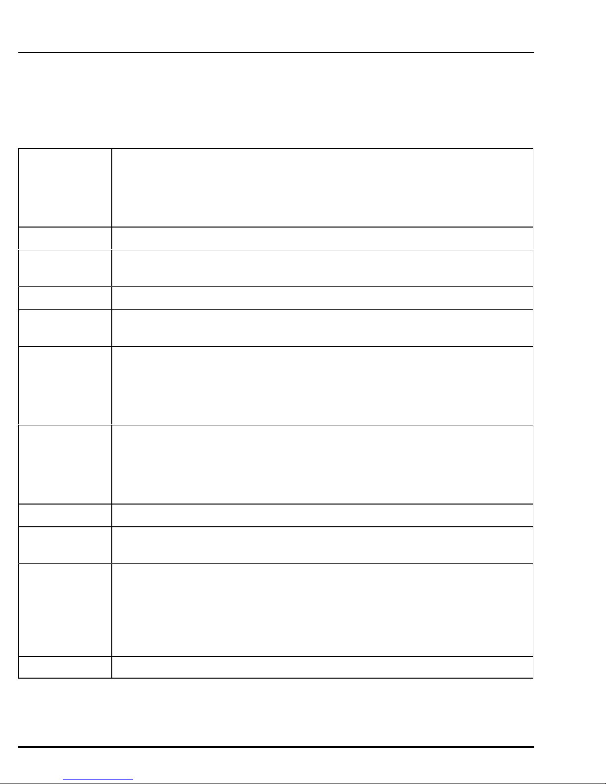
Electronics Enclosure
The electronics enclosure includes the microprocessor-based controller, the
peristaltic pump, and the liquid sensor. Constructed of structural resin, the
enclosure conforms to Nema 4X,6 requirements when latched.
The Controller
The controller electronics consists of 1 board. The board converts outside
power to the appropriate internal use and controls the input/output signals
associated with the sampler. The CPU board contains a Z180 microprocessor,
RAM and ROM memory, and interfaces for the keyboard, and the display. The micro board also contains the
logic for the liquid sensor and the RPM counter. The user communicates to the sampler via a 24 key multiple
function membrane switch. The keys are clearly marked with their designated functions. An internal battery
maintains the program logic, RAM memory, and the controller's real-time clock and date function. T he
electronics are mounted on the back of the controller.
Figure 1 - Electronics
Enclosure
April 1999/Manning Environmental Inc.
Page A-3
Page 14
INSTALLATION AND OPERATION MODEL YB8
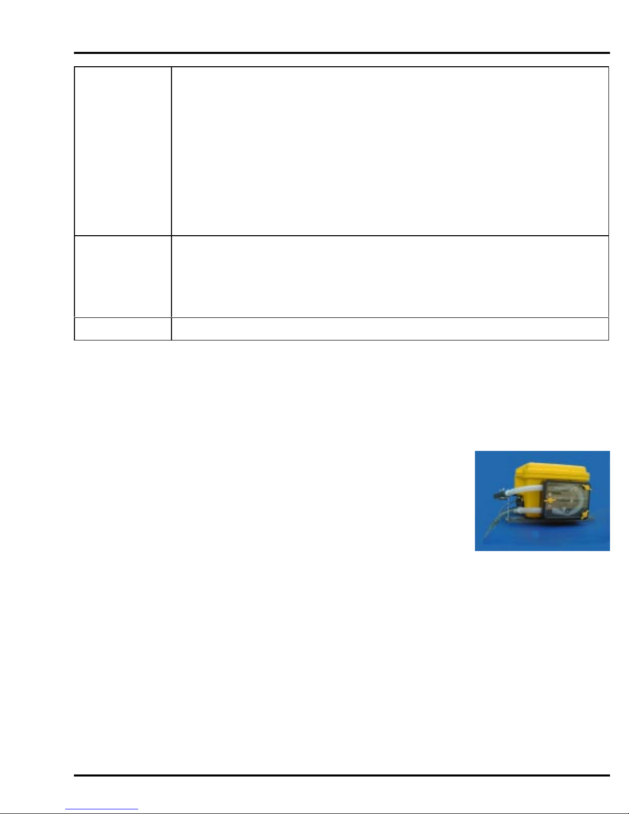
Peristaltic Pump
The Manning Model YB8 employs a high speed, dual
roller, vertically mounted, peristaltic pump. The pump is
belt driven by a 12VDC industrial grade motor. T his
ensures quite, smooth performance even while the unit is
subjected to very intense performance conditions. It
utilizes a face plate constructed of clear PVC for easy
visual identification of pump parameters, such as tube
alignment, and spindle and roller operation. The pump
body is made of impact and corrosion resistant Delrin
plastic for long life. It securely holds the pump tubing in
place by firmly clamping the two halves of the pump
case together. The pump is capable of vertical lifts of up
to 28 feet and produces sample transport velocities of
2.0 feet per second over a wide range of draw heights
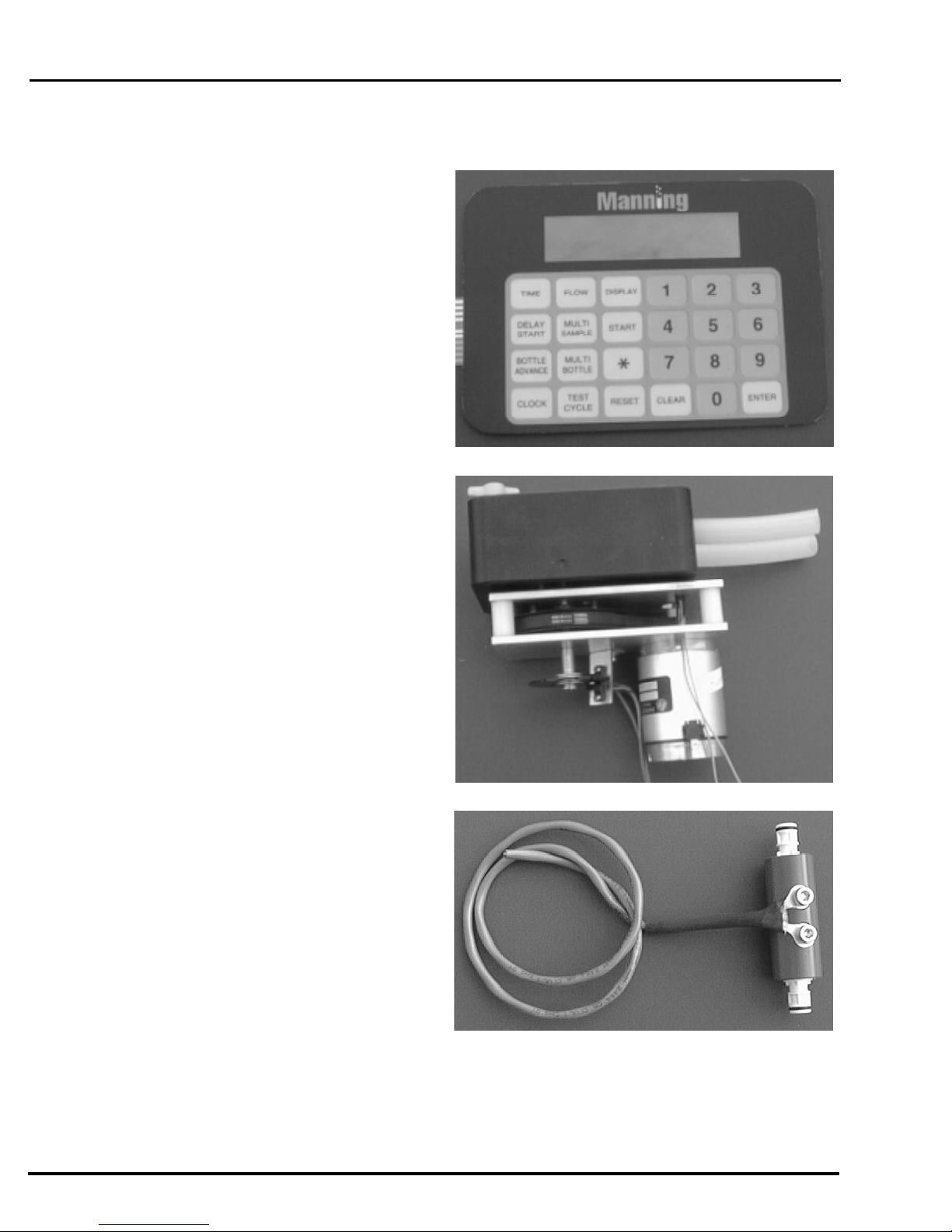
Liquid Sensor
®
Figure 3 - Keypad
The Model YB8 utilizes a liquid sensor, located near
the entrance to the peristaltic pump, which is capable of
detecting the presence of source fluid as it approaches
the pump inlet. The sensor is either a continuity type
probe (base) or an ultrasonic sensor (optional).
The liquid sensor is used for two reasons.It enables the
sampler to rinse the intake line. After the initiation of a
sampling sequence the first operation is to turn on the
peristaltic pump. The pump begins rotating
counter-clockwise causing air to be forced out of the
intake tubing. After the set amount of purge time has
elapsed, the unit will reverse the pump so the rollers are
moving in a clockwise direction. This creates vacuum in
the pump tube, which in turn causes the source liquid, to
begin traveling up the intake line. As soon as the fluid
reaches the liquid sensor, the sampler will immediately
recognize that fluid has reached the inlet to the pump. It
will instantaneously reverse the direction of the pump
(rollers will be moving in a counter-clockwise rotation),
sending the water that had been drawn up back out of
the intake line. This in effect rinses the line. When the
unit has performed the set number of rinses, a sample
will be drawn. The rinse option is set in *99
(configuration mode). The sampler can be programmed
to not rinse the line or to rinse the line up to 3 times.
Figure 2 - Pump Assembly
Figure 4 - Liquid Sensor - Continuity Type
It makes it possible for the sampler to deliver precise, repeatable samples even in changing lift conditions.
Page A-4
April 1999/Manning Environmental Inc.
Page 15
MODEL YB8 INSTALLATION AND OPERATION
Whenever a sampling sequence is initiated the sampler follows the steps outlined above, and draws a sample.
The controller then determines the transit time of the sample to reach the liquid sensor. Assume for example
there was an increase in the amount of lift from the source liquid to the unit. This would increase the time
needed for a sample to reach the liquid sensor and the pump. The controller, in a case such as this, will
automatically compensate for the change in lift by increasing the amount of time the peristaltic pump is able
to pull source liquid. This ensures the sampler has enough time to collect the correct amount of sample fluid.
The compensation applies to either an increase or decrease in lift height.
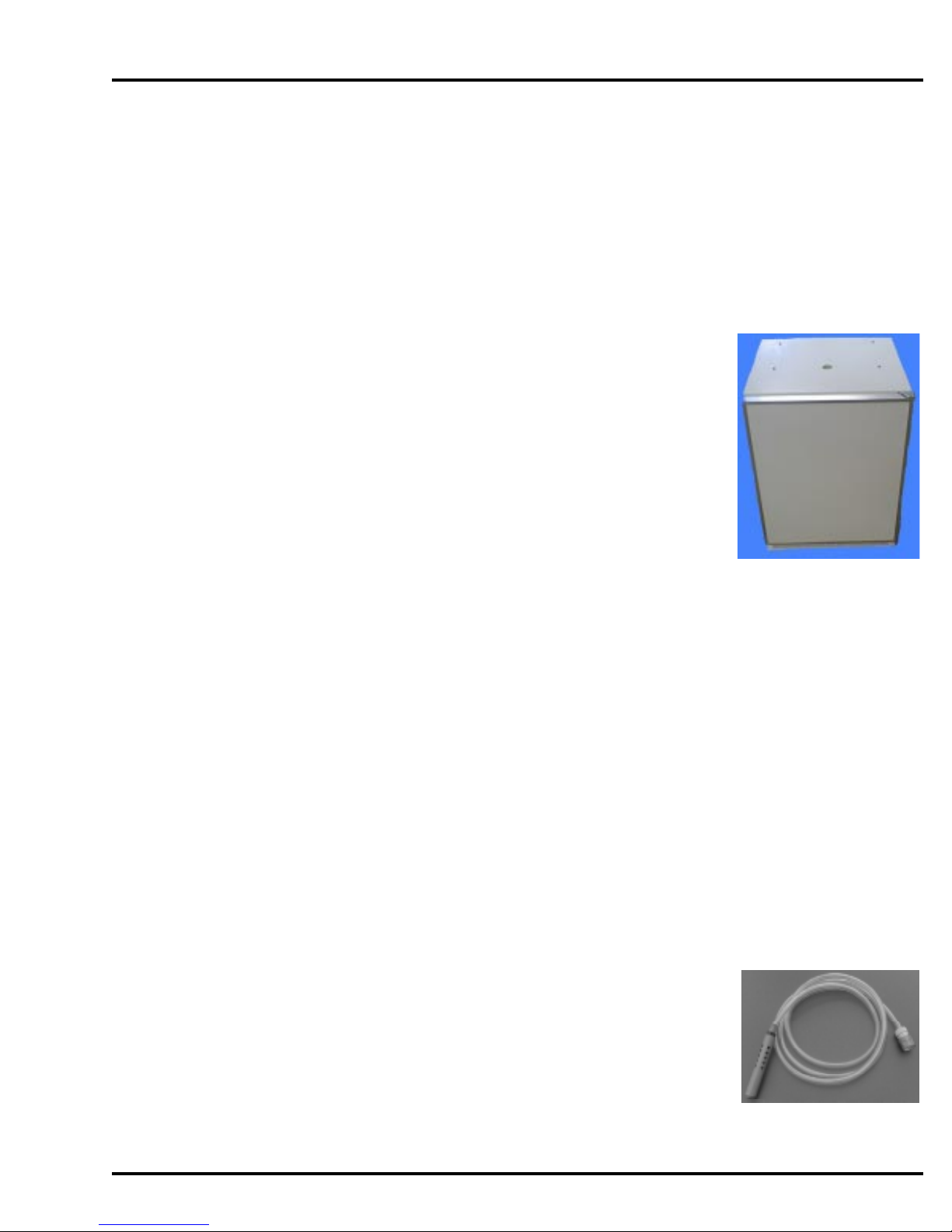
Refrigerator
The refrigerator is an industrial grade unit with the ability t o cool and maintain
samples at the EPA recommended 4ºC. Modifications have been performed on the
refrigerator that enable it to withstand event the harshest environments. The
condenser has been baked dip-coated with enamel and the copper refrigerant lines
are coated with asphalt cork tape to prevent hydrogen sulfide gas from attacking
the copper lines and the brazed joints. The thermostat is located inside the
refrigerator which affords it additional protection from the environment. The
evaporation coils and cabinet both have two coats of baked on acrylic enamel with
the cabinet having the additional protection of an iron phosphate pre-treatment.
Both the fan motor and t he compressor are designed for greater durability and
resistance to atmospheric attack. The unit boasts extensive insulation for
maximum cooling retention, and a full perimeter magnetic door gasket with a
urethane coating to resist corrosion and seal the cold inside. The door is also
available with an optional locking hasp to prevent unauthorized entry. The sample containers, suspension
plate, and distributor arm for multiple bottle operation are located within the environmentally controlled
chamber of the refrigerator.
Figure 5 - Refrigerator
Wetted Parts
Wetted parts are those pieces of the sampler that come in direct contact with the sample liquid. The main
components of the wetted parts for the Manning Model YB8 are the intake hose and strainer, the pump
tubing, the discharge tubing, the bottle full sensor (in single bottle units) the distribution assembly (in multiple
bottle units) and the sample bottles. If the source liquid t o be sampled is a non-priority pollutant (NonToxic) then all parts that touch the liquid are either PVC (Polyvinyl Chloride), medical grade silicone rubber,
ABS (Acrylonitrile Butadiene Styrene) plastic, or Stainless Steel. Parts in contact with a sample source that
is a priority pollutant (Toxic) are required to be Teflon , glass, stainless steel, or medical grade silicone
®
rubber. These materials are recognized and accepted as non-contaminating materials. This permits the
sampling of a wide variety of toxic pollutants such as hydrocarbons and chlorine-based compounds.
Intake Hose
The 3/8" ID by 5/8" OD intake hose is constructed of either PVC (Polyvinyl
Chloride) or PTFE. Y ou can differentiate the hoses by
their physical characteristics. The PVC is flexible and slightly tacky to the
touch. T he PTFE is not very flexible and is also very
smooth and slick to the touch.
Figure 6 - Intake Hose
April 1999/Manning Environmental Inc.
Page A-5
Page 16
INSTALLATION AND OPERATION MODEL YB8
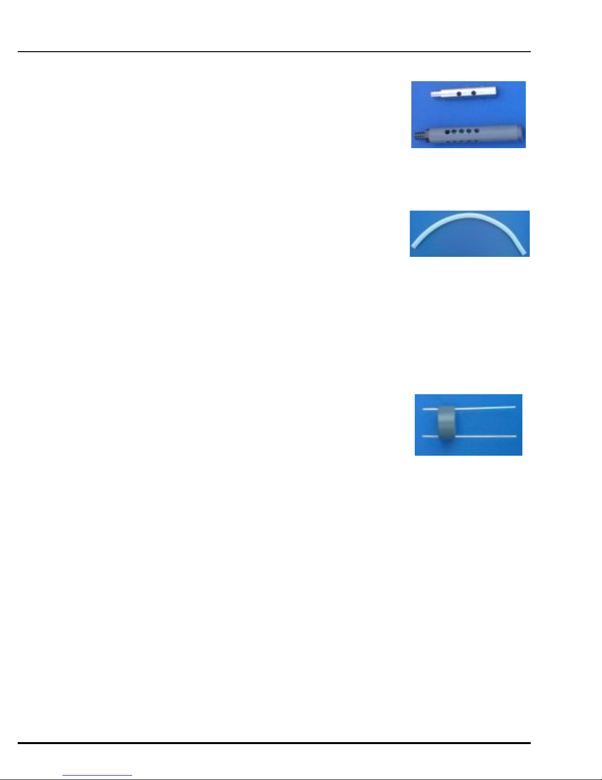
Bottle Full Sensor
Strainer
The 3/8" ID strainer is available in stainless steel, or PVC. By placing
holes no larger than 3/8" ID along the length of the strainer, the intake of
large particles that can plug the hose or any part of the sampler is
prevented. Since the strainer is also weighted, it keeps the hose inlet at the
desired level in the source liquid.
Pump Tubing
The pump tubing Manning Environmental Inc. supplies for the Model
YB8 is medical grade silicone rubber.
Discharge Tubing
The 3/8" ID by 5/8" OD discharge tubing is also medical grade silicone rubber.
Figure 7 - Strainers
Figure 8 - Pump Tubing
Bottle Full Sensor
The bottle full sensor is only used on single bottle applications. It is a
cylinder, with a hole in the middle, to allow the discharge tube to pass
through. Constructed of PVC it has two stainless steel rods that protrude
vertically downward from the main body of the sensor. The user positions
the bottle full sensor in the container with the ends of the rods at the highest
point water should be allowed t o rise. O nce the water level has risen and
contacts the rods, a change in continuity is detected alerting the sampling
unit that the liquid in the container has reached the maximum level allowed by the user.
This ends the sampling cycle
Page A-6
April 1999/Manning Environmental Inc.
Page 17
MODEL YB8 INSTALLATION AND OPERATION
Sample Bottles
The bottles are constructed of either polyethylene or glass.
NOTE: The sampler is field convertible from multiple bottle to single bottle.
Contact the Manning Environmental Parts Department for assistance.
Single Bottle Sampling Multiple Bottle Sampling
One (1) - 5 gallon HDPE carboy Twenty-four (24) - 500mL Polyethylene bottles
One (1) - 4 gallon polyethylene carboy Twenty-four (24) - 1000mL Polyethylene bottles
One (1) - 2.5 gallon glass bottle
One (1) - 2.5 gallon polyethylene
April 1999/Manning Environmental Inc.
Page A-7
Page 18

INSTALLATION AND OPERATION MODEL YB8
Assembly
Assembling the Model YB8 Sampler
The unit is normally shipped assembled with accessories packed inside the refrigerator.
Refrigerator
There are several things to keep in mind before installing the refrigerator. T he location is important.
It is best to locate the unit out of direct sunlight and away from heat sources. It is best to locate the
unit at least two inches away from any kind of wall. Ventilation is required from the bottom front
section of the unit. Keep this area open and clear of any obstructions. It is recommended not to use
a power cord to power the unit. It is best if the unit can be plugged directly into the appropriate
power supply outlet. The refrigeration system is equipped with a power supply cord that has a threepronged grounded plug. It must be plugged into a mating grounding type receptacle in accordance
with the National Electrical Code and applicable local codes and ordinances. If the circuit does not
have a grounding type receptacle, it is the responsibility and obligation of the customer to exchange
the existing receptacle in accordance with the National Electrical Code and applicable local codes an
dordinances. Th ethird ground prong should not under any circumstances, be cut or removed. All
U.L listed refrigerated products are equippedd with this type of plug, except hazardous location
models which are to wired to comply with the National Electrical Code, Article 501-4 for Class I
Divisions 1 and 2
Things to remember about the refrigerator:
A. Allow 24 hours for your refrigerator to reach a new temperature setting.
B. The motor will start and stop often. I t must do this to maintain the temperature you
select.
C. Keep you refrigerator as level as possible
D. Unplug the refrigerator before working on anything with the electrical system.
E. Exercise caution when sweeping, vacuuming or mopping near the front of the unit.
Damage to the grill can occur.
F. For all cleaning of the refrigerator, mix 2 tablespoons baking soda into 1 quart warm
water or use mild soap. D o not use strong cleaners or scouring powders or pads.
G. Keep all flame or sparks away from flammable material storage refrigerators when
opening the door to remove or store commodities.
H. Disconnect electrical power before removing electrical plug
Unpack the refrigerator by removing the bands at the top and bottom of the refrigerator box and
lifting the box off of the refrigeration unit. Open the refrigerator door and check for various
components that might be inside the refrigerator. I t ems are often packed inside the unit to minimize
shipping space. Check the items you have received against the packing list. Call Manning
immediately if yo u cannot match the packing list to the items shipped. M anning strives for 100%
accurate shipments, but mistakes do happen, so please call Manning immediately if t here is a
discrepancy.
Page A-8
April 1999/Manning Environmental Inc.
Page 19
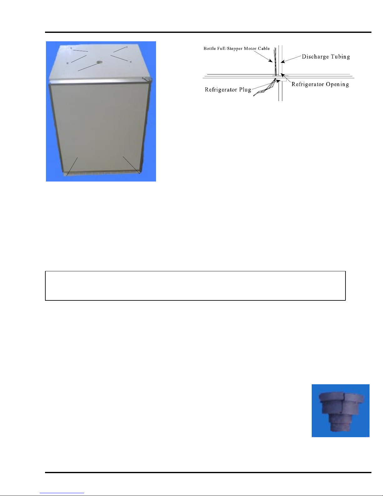
MODEL YB8 INSTALLATION AND OPERATION
Plus Nuts
Discharge Hole
Figure 12 - Refrigeration Hole Placement
1. Once you have unpacked the unit, locate the four feet
for the refrigerator (they are in a small plastic bag inside
Leveling Feet (2 front, 2 back)
2. With the refrigerator empty, carefully tip it and screw a
Figure 10 - Refrigerator
3. Adjust the feet so the refrigerator is level and does not
the refrigerator, with the refrigerator owners manual).
foot into the threaded hole in the bottom of each
corner.
rock.
4. Plug the refrigerator in and begin the cooling the unit down. Manning recommends using a
water proof thermometer and a liter of water to monitor the temperature of the water within
the refrigerator. T his will give a more accurate representation of the actual temperature of the
samples once sampling begins. Y ou should allow at least 24 hours for the refrigerator to
reach a stable condition.
NOTE: Be careful not to scratch any painted surfaces. The surfaces are painted with corrosion
resistant paint. S cratches in the paint minimize this protection.
Electronics Enclosure
1. On top of the refrigerator there will be 4 screws inserted into 4 plus nut holes. Remove the
screws from the holes and set them aside in a safe place.
2. Place the electronics enclosure on top of the refrigerator so the holes in the PVC mounting
bars match up with the threaded inserts in the refrigerator. The front (latches are in the front)
should be facing the door of the refrigerator and the peristaltic pump should be on the right.
3. Insert the screws and tighten snugly.
4. Thread the discharge tube into the center hole in the refrigerator. There
will be a black rubber plug that fits into the discharge hole. T his plug is
split to accept either the bottle full sensor cable or the stepper motor
cable depending on the configuration that you ordered. The cable fits
inside the plug.
Refrigerator Plug
Figure 11 -
April 1999/Manning Environmental Inc.
Page A-9
Page 20
INSTALLATION AND OPERATION MODEL YB8
Distribution Assembly Installation
Single Bottle Sampling
1. Center the sample bottle in the refrigerator.
2. Run the discharge hose through the Bottle Full sensor ring and then place it at the
desired height in the bottle. T o adjust the position simply slide the bottle full
sensor either up or down the discharge hose.
3. Connect the Bottle Full sensor probes to the female contacts on the bottle full
cable comming from the electronics enclosure into the refrigerator.
Multiple Bottle Sampling
Figure 13
Suspension Plate Installation
Position the suspension plate so the handles are on the sides. Slide the plate onto the top
rails in the refrigerator. The plate should be flush with the front of the refrigerator so it
does not interfere with the drain trough in the rear.
- Bottle
Full
Sensor
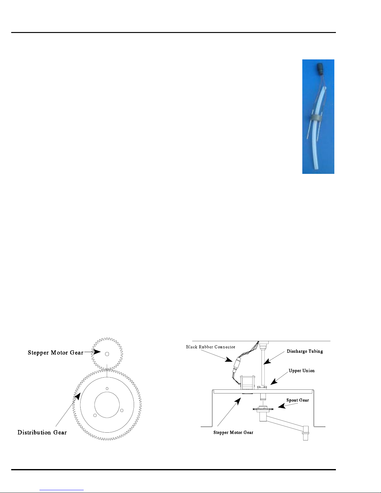
Distributor Assembly
1. Verify that the spout is correctly aligned on the distribution bracket. The spout should be centered
on the bracket side when the spout is rotated to the side (3 o'clock position).
Figure 14 - Gear Arrangement
Page A-10
Figure 15 - Distribution System
April 1999/Manning Environmental Inc.
Page 21
MODEL YB8 INSTALLATION AND OPERATION
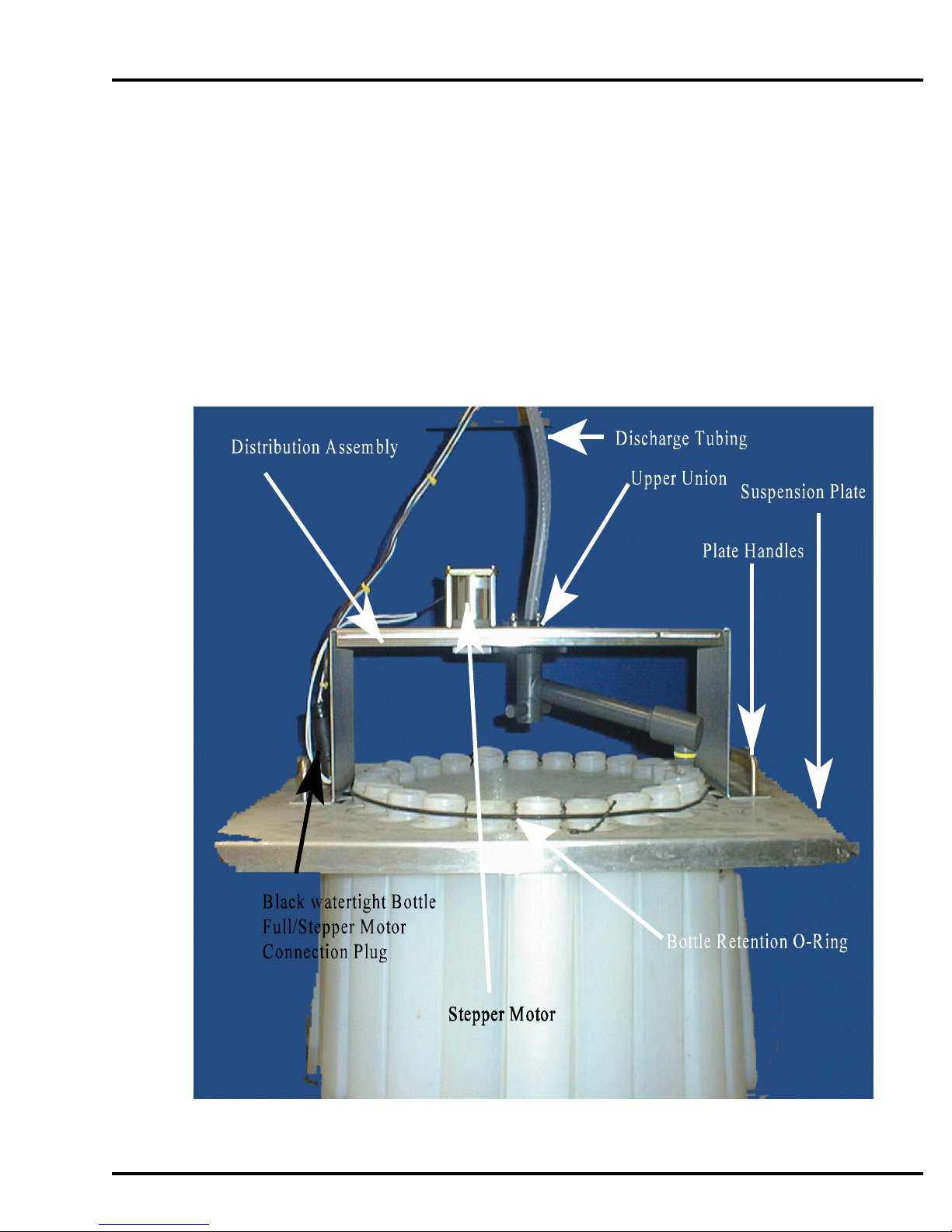
2. Place the distribution assembly on the suspension plate with the plate handles poking through
the slots in the distribution assembly.
3. Insert the discharge tube into the upper union. The discharge tube must be flush against the
union to prevent leaking.
4. Mate the black connectors. ( Applying non-conductive grease will help if d isassembly
is required later.)
There are wire racks inside the refrigerator so the distribution assembly can be parked out of the way when
removing the suspension plate and/or bottles. This makes it unnecessary to remove the discharge tube from
the spout union or to de-mate the connector when removing the plate.
April 1999/Manning Environmental Inc.
Figure 16 - Distribution Assembly Picture
Page A-11
Page 22

INSTALLATION AND OPERATION MODEL YB8
Page A-12
April 1999/Manning Environmental Inc.
Page 23
MODEL YB8 INSTALLATION AND OPERATION
The bottles can be installed with the suspension plate in the refrigerator, or the plate can be removed,
the bottles installed, and the plate positioned back in the refrigerator.
Follow the instructions below fro the type of bottles being installed.
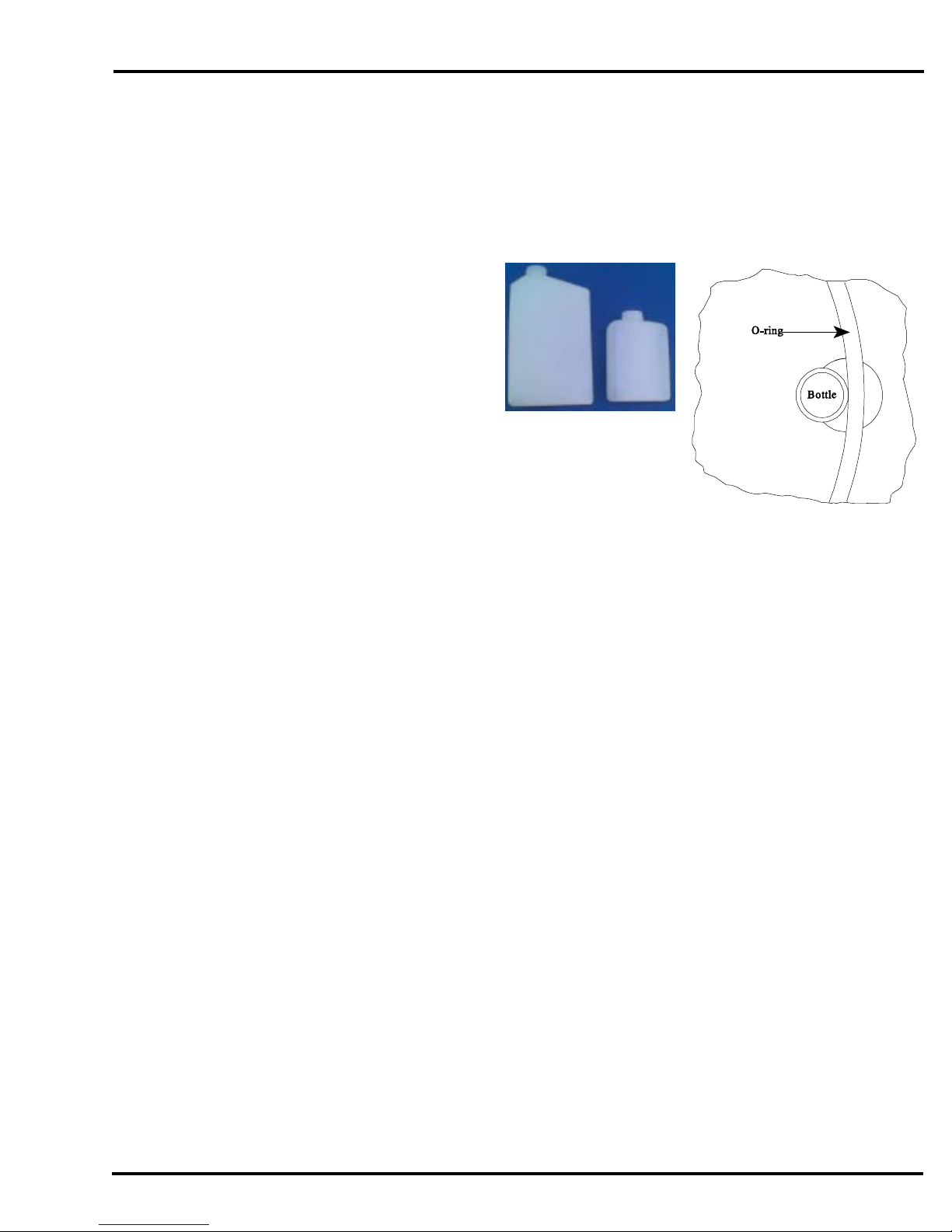
One Liter and Half-Liter Plastic Bottles
1. Insert the bottles through the larger
part of the hole in the suspension
plate.
2. Place the bottles so the smaller angled
part of the bottles points in toward the
middle of the case. Snap each bottle
into place in the smaller part of the
hole. Be sure the bottles are held
below the threaded section.
Figure 21 - 1 liter
(left) and 500ml
(right) bottles
3. Secure bottles by placing the o-ring around them
.
Figure 20 -
Bottles Installed in Suspension
1 Liter and 1/2 Liter
Plate
Spout Position
If the suspension plate was removed from the refrigerator,
replace it. Place the spout over the last bottle in the series,
since the first action of the sampling cycle is a spout
advance.
Installing The Sampler
Install the sampler on a firm, level surface adjacent to the sampling point. If the sampler is installed outdoors,
consider enclosing it in a shelter or under some sort of protection. T his will improve the performance and life
of the unit. The Manning Parts Department can supply an optional full-size NEMA 3R insulated fiberglass
enclosure designed for this purpose.
Connecting Power
The YB8 sampler was designed with components which operate on 12 VDC power. Recognizing
that 115 VAC power has to be available to run the refrigerator, the sampler takes advantage of the
constant supply by employing an AC/DC converter to provide power to the system. The converter is
located inside the electronics enclosure. It comes equipped with a power cord, but it can be hard
wired if desired. A power switch, which controls flow of current to the controller and peristaltic
April 1999/Manning Environmental Inc.
Page A-13
Page 24
INSTALLATION AND OPERATION MODEL YB8
pump, is located on the front of the electronics enclosure. The refrigerator has its own individual
power cord. By using the AC/DC converter the user does not have to be concerned with replacement
of batteries, charging of batteries, or any other factors which affect 12 VDC systems. The system has
been thoroughly tested using 115 VAC and will provide outstanding service, reliability, and longevity.
To power t he unit up follow these simple steps:
1. Check to make sure that the pump cover is
securely fastened to the pump housing and that
the unit is ready to be powered up.
2. Locate the power plug coming out of the
electronics enclosure.
3. Plug the AC/DC converter into the appropriate
receptacle.
4. Turn the power switch, located on the right side
of the electronics enclosure, to "ON". Verify, by
looking at the display, that power is being
applied to the system. If the display does not light up, confirm that the appropriate
connections have been made. I f the unit does still not power up, call the Manning Service
Department. T hey will be able to provide assistance in getting the unit operat ional.
WARNING: Hard-wiring should only be done by a certified electrician.
Sample Intake Line
Attach the intake hose to the connector at the end of the pump tubing.
Intake Hose Placement
Place the intake hose strainer directly in the channel flow, not in an eddy or at the edge of the flow.
In channels with debris, provide deflection to prevent clogging of strainer holes. The weight supplied
with the intake hose is usually sufficient to prevent the intake from being pulled to the surface of a
fast channel.
The correct vertical position of the strainer depends on the type of sample being taken. Placing the
strainer at the bottom of the flow results in a heavier concentration of solids in the sample, while
placing the strainer at or near the top of the flow results in heavier concentration of oils, fats, and
other floating or suspended contaminants.
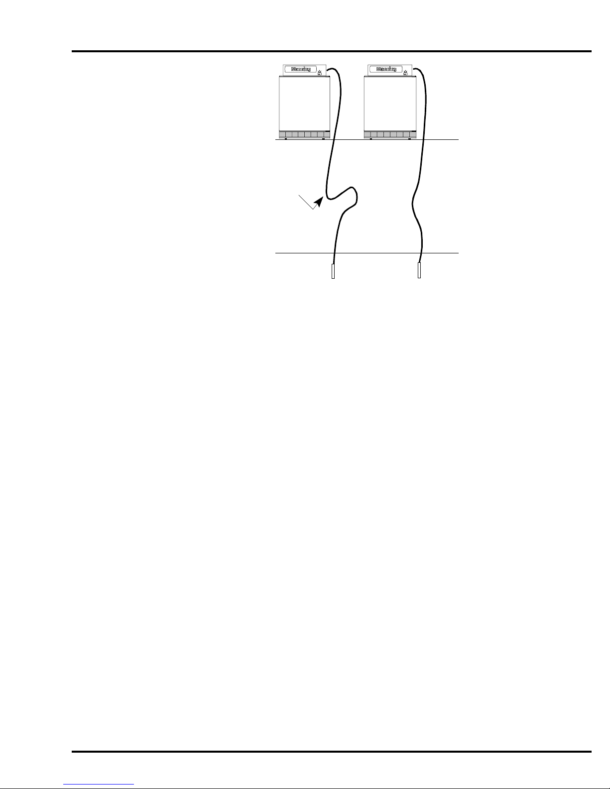
The intake hose should be positioned so the hose can drain between sample cycles and no low spots
exist which would trap water. The correct and incorrect hose placements are shown below.
Page A-14
April 1999/Manning Environmental Inc.
Page 25
MODEL YB8 INSTALLATION AND OPERATION
Trap
Incorrect
Installation
Correct
Installation
Water Level
Figure 24 - Intake Hose Placement
Running A Test Cycle
While it is not mandatory to run a test cycle, it is recommended to assure proper operation and to become
familiar with the various functions and modes of operation. Run a test cycle before programming any
operational modes into the sampler.
1. Turn the main power switch to the “ON” position. The display should read “Sampler Ready”.
2. If the multiple bottle option is being used, rotate the spout so it is over a bottle.
3. Submerge the strainer of the intake hose in a container of clean water. The amount of water
should be enough to keep the strainer covered completely for several test cycles.
4. Press the TEST CYCLE key on the keypad to initiate the test cycle. Y ou will be prompted
for the number of samples you want to take. Enter the number and press <ENTER>.
The Sampling Cycle
Refer to the errata (pages 9-11) at the end of this manual for sampler theory of operation.
There are two types of sample events. The first is time-based. In this type a time interval is defined and the
sampler places a sample in each bottle based on that time interval.
The second type of sample event is flow-based. In this type an external flowmeter provides one of two types
of signals: a contact closure when a specified amount of liquid has flowed past the measurement point; with
the analog option, an analog signal proportional to flow rate.
April 1999/Manning Environmental Inc.
Page A-15
Page 26

INSTALLATION AND OPERATION MODEL YB8
Whether the sample event is triggered by a flowmeter or by a time interval, the actual sampling cycle is the
same. For the multiple bottle option, the first action is the advance of the spout to the next bottle. (For single
bottle samplers, this step is omitted.) Next, the sampler turns on the peristaltic pump. The pump begins
rotating counter-clockwise causing air to be forced out of the intake tubing. This clears the intake hose of
any contents or obstructions that may inhibit proper sample collection. After the set amount of purge time
has elapsed, the unit will then reverse the pump so that the rollers are now moving in a clockwise direction.
This causes vacuum to be created in the tube, which causes the source liquid, to begin traveling up the intake
line. I f the unit was programmed to rinse, as the source liquid rises in the intake line it will reach the liquid
sensor. T he sampler will immediately recognize that fluid has reached the inlet to the pump. It will
instantaneously reverse the direction of the pump (rollers will be moving in a counter-clockwise rotation),
sending the water that had been drawn up back out of the intake line. This in effect rinses the line. If the unit
was not set for a rinse the above steps wil be ommited. U pon completion of the last rinse, source liquid will
again be drawn up the intake line. The system monitors the flow of liquid and when the preset amount has
passed through, the pump will reverse operation again (rollers moving counter-clockwise). T his purges
excess fluid out of the pump and clears the intake line. Depending on how the unit is programmed or
configured, after completing the post sample purge, the sampler will now stop operation or continue
performing those functions which it has been programmed. F or a complete description of programming the
sampler see the programming section in this manual.
If the multiple bottle option is being used, the distribution spout remains stationary until the next sample
event. This delay prevents cross-contamination of the next sample.
Sample Recovery
Immediate sample recovery is not required since the sampler will automatically shut down when the sample
container is full (single bottle only), a pre-set number of samples have been taken, or when the program is
complete. However, sample analysis may require quick recovery to maintain sample freshness or to add
chemicals.
If the intent is to leave the containers in the suspension plate, caps can be installed over the suspension
collars. Remove the suspension plate (with bottles) from the refrigerator. Lift the distribution assembly off
the suspension plate and place it on the wire racks mounted in the refrigerator.
It may be easier to remove the distribution assembly first, and then install the bottle caps. To seal the 350ml
glass bottles, replace cap liners, then place caps on bottles.
Page A-16
April 1999/Manning Environmental Inc.
Page 27
MODEL YB8 INSTALLATION AND OPERATION
External Connections
Refer to the errata (page 3) for more information on connecting to an external device.
DANGER: Turn the sampler off at the power switch and unplug the power supply before
making connections. Injury can result if the power is present when making
connections.
The following chart describes the external connections which are necessary to operate the sampler:
Contact In & Analog In Connections
Purpose Connector Designation Color Polarity
Contact In A Red No Polarity
Contact In B Black No Polarity
Analog In (+)
Analog In ( - )
Bottle Full/Stepper Motor
The Model YB8 can utilize both a Bottle Full Sensor and Stepper Motor (not at the same time).
Connections for the Bottle Full Sensor and the Stepper Motor are hardwired to the unit. If the unit was
purchased as a single bottle unit only, the wires for multiple bottle operation are not run. If multiple bottle
operation is desired, a conversion of the unit to multiple bot tle operation will need to be done at the factory.
To connect them follow the instructions listed below:
D White Positive
C Green Negative
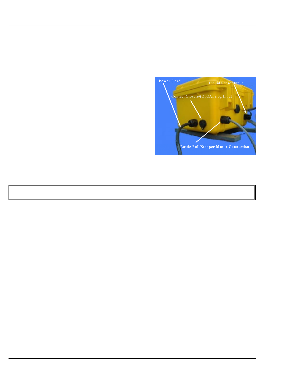
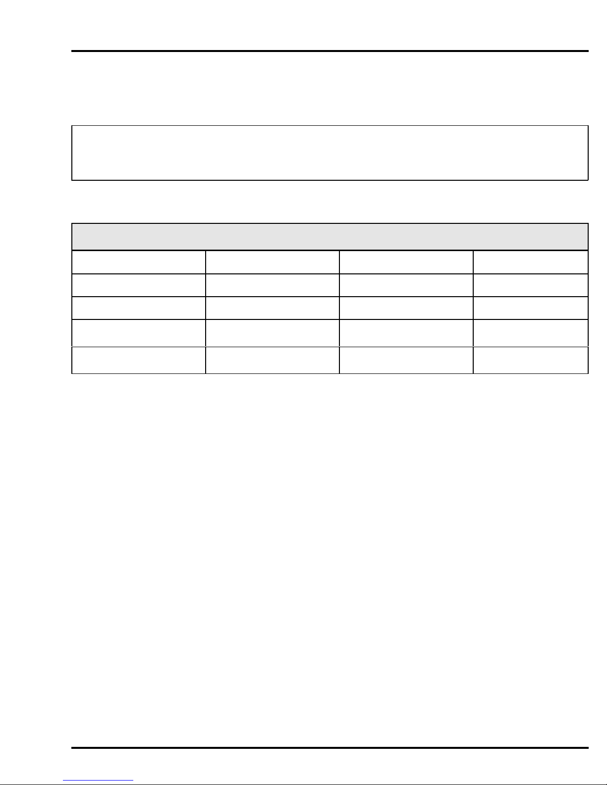
A) Locate the cable comming out of the bulk head fitting on the left front of the electronics
enclosure. It runs down through the top of the refrigerator. For single bottle units, there are two
female contacts on the end. For multi-bottle units, there is a black connector.
April 1999/Manning Environmental Inc.
Page A-17
Page 28
INSTALLATION AND OPERATION MODEL YB8
B) Connect either the bottle full sensor or the stepper
motor to the cable.
NOTE: I f this connection is not made, neither the Bottle
Full Sensor nor the Stepper Motor will function.
Figure 25 - Electronics Enclo
sure
Contact Closure
This enables the sampler to accept a contact closure from, an external device. The parameter to be measured
is set, recorded, and totalized by the external device. When the set limit is met, a contact closure will be sent to
the sampler. T his in turn will initiate the sample collection process.
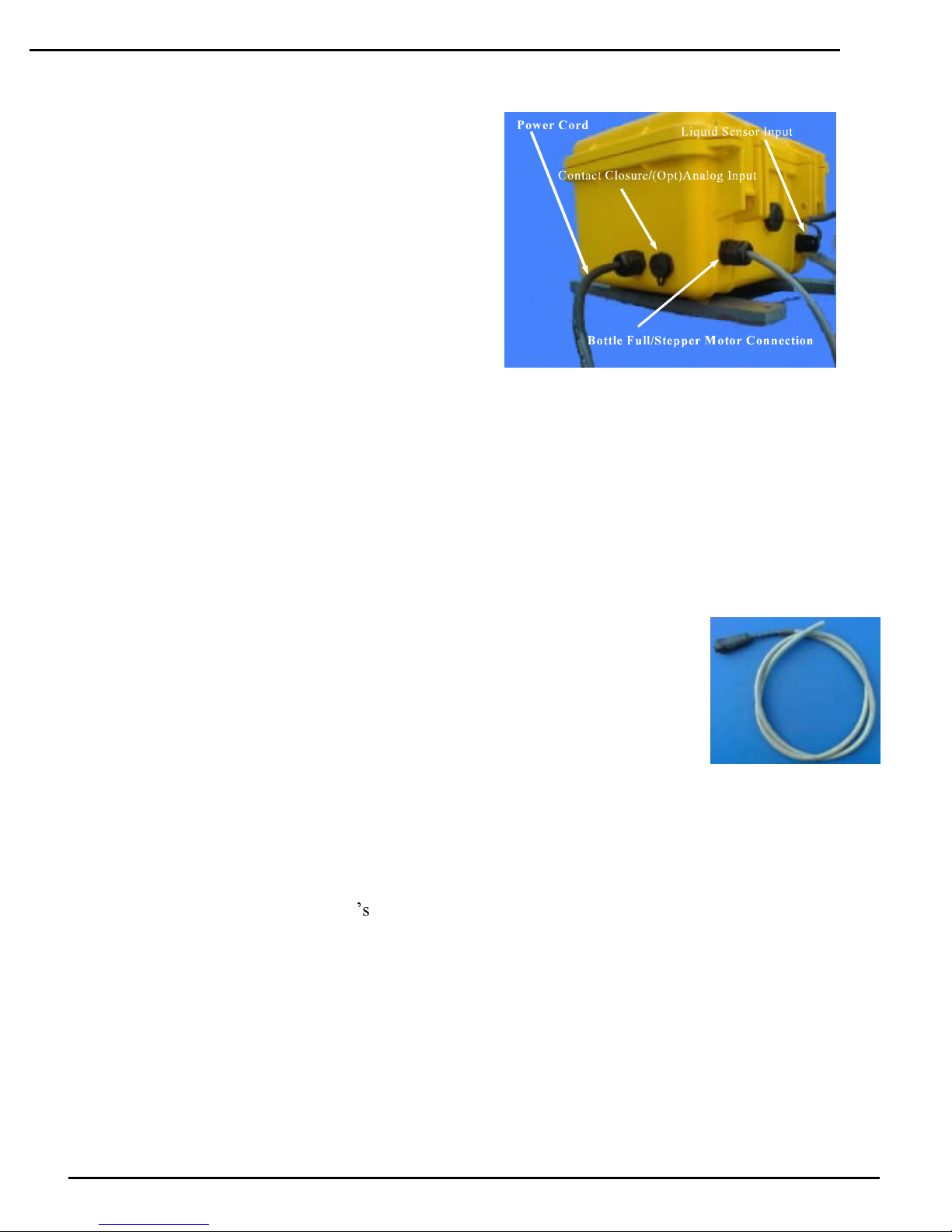
The sample comes standard wtih a 3 foot cable for connecting to external devices.
To connect the external device to the sampler follow the steps listed below:
A) Locate the connector on the left side of the electronics enclosure.
If the sampler has the Analog Option, it will be labeled Contact In/Analog In.
B) Wire the red and black wires to the external device's contact closure output.
C) Re-connect the cable to the connector on the enclosure.
This should complete the installation of the contact closure. Test the connection by
initiating a closure through the external device to verify the wiring is correct and the
sampler is initiating a sampling cycle when a closure is received.
Figure 27 - Contact
In/Analog In Cable
Analog Signal (Optional)
With this option, the sampler can accept an external 4-20mA signal from an external device. The flow
volume is internally totalized by the sampler*s controller. The analog option is not available as a field retrofit.
Contact the Manning Parts Department to discuss a factory modification. To connect the external device to
the sampler follow the steps listed below:
A) Locate the connector on the left side of electronics enclosure which is labeled "Contact/Analog In".
Page A-18
April 1999/Manning Environmental Inc.
Page 29

MODEL YB8 INSTALLATION AND OPERATION
B) Wire the white (+) and green (-) wires to the external device’s analog output.
C) Re-connect the cable to the "Contact/Analog In" connector.
This should complete the installation of the contact closure. Test the connection through the external device
to verify the wiring is correct and the sampler is initiating a sampling cycle when the signal is received. See
the *08 Mode in the Programming section for additional information.
This completes the installation of the sampler. The unit should now be operational. Proceed to the
programming instructions to program the sampler for operat ion.
April 1999/Manning Environmental Inc.
Page A-19
Page 30

Page 31

MODEL YB8 PROGRAMMING
Programming
Section Contents
Introduction ........................................................................................................................................... Page B-1
Sampler Configuration .......................................................................................................................... Page B-1
Sampling Modes ................................................................................................................................... Page B-1
Multi-Bottle Sampling Modes .................................................................................................. Page B-1
Single Bottle Modes .................................................................................................................. Page B-1
<RESET> .................................................................................................................................. Page B-2
<TEST CYCLE> ...................................................................................................................... Page B-2
<BOTTLE ADV> ..................................................................................................................... Page B-2
<CLEAR> ................................................................................................................................. Page B-2
<CLOCK> ................................................................................................................................ Page B-2
<DISPLAY> ............................................................................................................................. Page B-2
*................................................................................................................................................. Page B-2
EEEE ......................................................................................................................................... Page B-2
Key Not Active ......................................................................................................................... Page B-2
Display Information .............................................................................................................................. Page B-3
Time of Day .............................................................................................................................. Page B-3
Program Status .......................................................................................................................... Page B-3
Sampler Ready .............................................................................................................. Page B-3
Programming................................................................................................................. P age B-3
Active Program ............................................................................................................. Page B-3
Sampler Configuration Functions ......................................................................................................... Page B-4
*99 Sampler Set-Up .................................................................................................................. Page B-4
*20 Volume Calibration ............................................................................................................ Page B-7
*19 Pump Utilities .................................................................................................................... P age B-9
*91 Data Logging ................................................................................................................... P age B-11
ID Menu ...................................................................................................................... Page B-12
View Menu.................................................................................................................. Page B-12
Exit Menu.................................................................................................................... Page B-16
Download Menu.......................................................................................................... Page B-16
Clear Menu.................................................................................................................. Page B-18
*14 Clear Log Data ..................................................................................................... Page B-18
Analog Option Programming .............................................................................................................. Page B-19
Totalizing ................................................................................................................................ Page B-19
*08 Analog Display Routine ....................................................................................... Page B-20
Add-On Programming Functions ........................................................................................................ P age B-22
April 1999/Manning Environmental Inc.
Page 32

MODEL YB8 PROGRAMMING
Multiple Bottles per Sampling Event ...................................................................................... Page B-22
Multiple Samples per Bottle ................................................................................................... Page B-22
Delay Start - Time ................................................................................................................... Page B-24
*15 - Active Sampling ........................................................................................................Page B-24-A
General Programs................................................................................................................................ Page B-25
Time Mode - *START ............................................................................................................ P age B-25
Time Mode - Single Time Interval ......................................................................................... Page B-26
Flow Mode .............................................................................................................................. Page B-28
Flow Mode - Pulse Accumulation .......................................................................................... P age B-29
Multi-Bottle Sampling Programs ........................................................................................................ Page B-30
*01 Flow Mode - Independently Time Spout Advance .......................................................... Page B-30
*02 Flow Mode - Time Interval Override............................................................................... Page B-31
*03 Flow Mode - External Event ............................................................................................ Page B-32
*04 Time Mode - Multiple Intervals ....................................................................................... Page B-33
*07 Flow Mode - Time Delay Interval ................................................................................... Page B-35
Analog Sampling Programs ................................................................................................................ Page B-36
*05 Flow Mode - Totalizing Analog ...................................................................................... Page B-36
*06 Analog Level Mode ......................................................................................................... Page B-38
*09 Hydrologic Level Event Mode ......................................................................................... Page B-41
Multi-Bottle Flow Composite Programs ............................................................................................. Page B-45
*10 Flow Mode - Multiple Bottle Composite ......................................................................... Page B-45
*11 Flow Mode - Totalizing Analog Multiple Bottle Composite........................................... P age B-47
*12 Flow Mode - Multiple Bottle Composite with Bottle Groups ......................................... Page B-49
*13 Flow Mode- Totalizing Analog Multiple Bottle Composite with Bottle
Groups ..................................................................................................................................... Page B-52
April 1999/Manning Environmental Inc.
Page 33
MODEL YB8 PROGRAMMING SECTION
Introduction
The sampler is controlled by a microprocessor that can execute a wide variety of time and flow sampling
sequences called Modes. Entries are made through a keypad with prompts displayed on a 2 line by 20
character backlighted LCD (Liquid Crystal Display).
Sampler Configuration
For the sampler to function properly, it must be set-up for the specific application in which it will be used. T he
*99 Function configures the sampler. Configuration defines multiple variables that do not usually change
between different applications. These are such things as the type of sampler (single bottle, multiple bottle, or
storm water), the number of bottles, and other factors like draw time, and purge time. Instructions for
configuration of the sampler begin on page 2-5.
Sampling Modes
The sampler has two basic Modes: Time and Flow. (NOTE: While referred to as Flow Mode, the sampler
can actuate based on signals from any external device. What device or why the device is supplying the closure
is transparent to the sampler. The sampler simply registers a contact closure, so actuation can occur based on
pH, ORP, Level, Flow, or other parameters. Time mode is based on a preset time period that must pass
before a sample is taken. Flow mode has two variants. The standard controller (contact closure option)
allows sampling based on contact closures from an external device. The analog controller (4-20mA option)
allows sampling based on an analog signal totalized by the sampler’s controller. All programs (or Modes)
available for the Model YB8 are based on either Time or Flow. Instructions for programming the different
Modes begin on page 2-14.
Multi-Bottle Sampling Modes
All of the programs or Modes can be used with multiple bottle samplers.
Single Bottle Modes
All General Programs (Basic Time and Flow Modes)
*02 Time Interval Override Mode
*04 Multiple Time Intervals Mode
*05 Totalizing Analog Flow Mode
*06 Totalizing Analog Level Mode
April 1999/Manning Environmental Inc.
3DJH%
Page 34
PROGRAMMING SECTION MODEL YB8
Utility & Display Functions
Key Function
<RESET>
<TEST CYCLE>
<BOTTLE ADV>
<CLEAR>
<CLOCK>
<DISPLAY>
Functions as a Reset (a soft boot in computer terms) for the sampler and clears
the current program mode.
Allows the user to check the sampler for mechanical operation by taking a
physical sample.
Advances the spout clockwise 1 bottle each time the key is pressed. This
function will not work when a program is running.
Clears invalid and incorrect entries before <ENTER> has been pressed. Also
allows the user to step the cursor back 1 movement, clearing entries each time
the key is pressed.
Sets the time and date. To set, press RESET twice, press CLOCK, enter the
time and date and then press <ENTER>. NOTE: All times are entered and
displayed in 24 hour HH:MM format. For example, 6 hours would be entered as
0600 and a real time of 3:30 p.m. would be displayed as 15:30.
Shows current program or configuration information. T he information displayed
depends on whether the user is in or out of a programmed mode. If the user is
out of a programmed mode, pressing <DISPLAY> will show the configuration
settings input in *99. If the user is in a programmed mode (e.g. a TIME, FLOW,
or * Mode), pressing <DISPLAY> will show the current time, spout position,
and other information specific to the current mode. NOTE: See Appendix B for
a Logic Map of the Programming Modes and what displays are active when the
Display key is pressed.
*
EEEE
Key Not Active I
3DJH%
Used to program Star Modes.
Indicates an error condition has occurred. Press CLEAR to reset, and re-enter
the data.
ndicates the key pressed is not active at the current time.
April 1999/Manning Environmental
Page 35

MODEL YB8 PROGRAMMING SECTION
Display Information
The Manning sampler is capable of displaying a wealth of information through the 2 line by 20 character
display. The following describes the functions and how they can be of benefit to the user:
Time of Day The time of day is always displayed in the bottom right hand corner of the
display. The format is a 24 hour clock HH:MM:SS. If the display is not
counting down the seconds, the controller may have quit functioning. Press
<RESET> to warm boot the system. If this does not clear the
problem, please call Manning at 1-800-863-9337.
Program Status The bottom left hand corner of the display is used for indicating miscellaneous
program and functional information. T he information displayed here varies
depending on the operational status of the active program. The following
highlights the function of the display in different modes:
Sampler Ready Shows time of day in HH:MM format (24 hour clock)
Programming In programming situations, the display is used for entering the dat a required by
the particular mode that is being programmed.
Active Program The information displayed depends on the type of program and the status of that
program. When a time is shown in this section of the display it is signified by a
flashing colon. T he time shown may signify time to sample, time override, purge
time, draw time, or other times associated with the program. All time displays
are in HH:MM format, except for configuration function times (draw time, purge
time, measure time, deposit time) and *07 DELAYED SAMPLE EVENT
MODE which are shown in MM:SS format. Non time displays are characterized
by a 4 digit display which does not posses a flashing cursor. The information
relayed here may be the sample number or the bottle number depending on the
active program and its state.
April 1999/Manning Environmental Inc.
3DJH%
Page 36

PROGRAMMING SECTION MODEL YB8
Sampler Configuration Functions
There are 3 major configuration functions the user must be concerned with (*99, *20, & *19). Step-by-step
programming instructions and descriptions of each function are detailed on the pages that follow :
*99 Sampler Set-Up
*99 allows the user to set the sampler’s configuration. For proper operation, it is critical the unit is correctly
configured. The memory comes preset with the sampler’s defaults. These defaults can be reviewed or
changed by entering the configuration mode (explanations and step-by-step instructions are given below).
Once entries have been made in *99, re-entering the configuration mode is not necessary unless changes in the
data are needed.
Display on LCD Explanation
SAMPLER READY
04/30 04:30:02
ENTER * MODE?
__ __ 04:30:02
SAMPLER SETTING?
__ 04:30:02
# OF BOTTLES?
__ __ 04:30:02
SAMPLE VOLUME?
__ __ __ __ 04:30:02
This display shows the sampler is ready to program. I t displays the
current time. From here the user can enter any TIME, FLOW, or *
Mode. Press the * key to access the * Mode.
Prompts the user to enter either a program or the configuration
function. Press 99 and <ENTER> to configure the sampler.
Sets the sampler to a specific type of operation or bottle
configuration:
1 = Single Bottle
2 = Multi-Bottle
Other numbers are not valid and will cause the sampler to
malfunction. Enter the desired configuration and press <ENTER>
Sets the number of bottles (1,2,3,4,6,8,12, or 24) in the sampler. If 1
was selected for the SAMPLER SETTING above, this prompt is
bypassed. Input the number of bottles and press <ENTER>.
Sets the sample volume (in milliliters), to be collected per sample.
TUBE LENGTH?
__ __ __ __ 04:30:02
DRAW HEIGHT?
__ __ __ __ 04:30:02
3DJH%
Records the length (1 to 99 feet) of the sample intake tube.
Sets the draw height or lift height (1 to 25 feet) of the sampler.
April 1999/Manning Environmental Inc.
Page 37

MODEL YB8 PROGRAMMING SECTION
RINSES PER SAMPLE?
__ __ __ __ 04:30:02
BOT VOLUME, LITERS
__ __ __ __ 04:30:02
PURGE TIME?
__ __ 04:30:02
DRAW TIME?
__ __ __ 04:30:02
Sets the number of rinses (0-3) the sampler will perform per sample
cycle.
This tells the sampler the volume of the current cont ainer you have in
the system. T he volume is set in terms of full liters. S o an entry of
00.50 would be 500ml or 1/2 liter. An entry of 15.00 would be 15
liters. T his is used in conjunction with the number of samples to be
taken so that overfill of the bottle(s) does not occur. F or reference
the following is a chart with gallons and the equivalent liters:
6 Gallons = 23.05 Liters 5 Gallons = 19.20 Liters
4 Gallons = 15.36 Liters 3 Gallons = 11.52 Liters
2.5 Gallons = 9.60 Liters 1 Gallon = 3.84 Liters
Length of time (3-99 secs) the intake line is purged before a sample
is taken. Press <ENTER> to accept the default purge time or input a
new 2-digit number. If air bubbles are not coming out of the intake
line, or if fluid is visible in the line after the purge has been
completed, increase the purge time.
Time window (4-150 secs) during which a sample is drawn. Press
<ENTER> to accept the displayed draw time or input a new draw
time as a 3-digit number and then press <ENTER>. If the sample
fluid does not reach the liquid sensor, increase the draw time.
AUTO RESTART?
__ 04:30:02
TEST CYCLE MODE?
__ 04:30:02
Sets the auto restart mode: 0 - No auto restart; 1 - auto restart
activated. This option will restart the sampler and continue the
program that was running, if power fails. It stores parameters,
ensures orderly shutdown, and stores enough energy to complete any
stepper motor steps in progress.
Sets the test cycle mode. Press <ENTER> to accept the default or
input a new number corresponding to the manner in which test
samples are to be taken:
0 - Only when the sampler is not running a program.
1 - In a program, but the sample does not count in the program.
2 - In a program, and the sample counts in the program.
April 1999/Manning Environmental Inc.
3DJH%
Page 38

PROGRAMMING SECTION MODEL YB8
BACKLIGHT MODE?
__ 04:30:02
ENTER PASSWORD
__ __ __ __ 04:30:02
Sets whether the display backlights:
0 - Backlight is never on. This is good if power conversation is
critical.
1 - Backlight comes on when a key is pressed. T he light will
automatically turn off after 30 seconds if another key is not
pressed.
2- Backlight comes on when a key is pressed and also at the start of
a sampling cycle. T he light will automatically turn off after 30
seconds if another key is not pressed or another sampling cycle is
not initiated.
3- Backlight is always on. T his choice will quickly run down a
battery.
Creates a password to stop unauthorized access. There are 2
options:
A. Press <ENTER> to accept no password - 0000 (default
shown)
B. Enter a 4-digit number at the prompt and press <ENTER>.
The user will be prompted to verify the password. E nter the
same 4 digits and press <ENTER>. This sets the password.
RECORD the numbers. To change a password, enter *99
mode and input the 4 digit numeric password at the
PASSWORD PROTECTION prompt. Press <ENTER>.
The user can now go into *99 and at the ENTER
PASSWORD prompt, create a new password.
Note: Use a TEST CYCLE setting of 0 if TEST CYCLE is to be
password protected while a program is running.
If the password is forgotten, call the Manning Service Department at
(800)-863-9337.
After finishing the Configuration Mode, the sampler will return to the Sampler Ready prompt and the current
time will be displayed. C onfiguration is now complete, and the sampler is ready for programming.
3DJH%
April 1999/Manning Environmental Inc.
Page 39
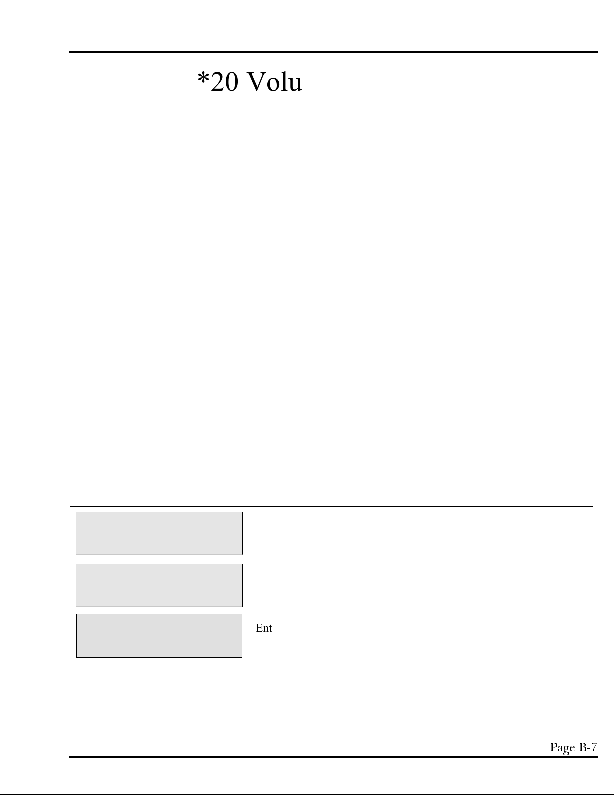
MODEL YB8 PROGRAMMING SECTION
SAMPLE VOLUME?
0200 04:30:02
*20 Volume Calibration
*20 calibrates the unit. Calibration is critical to ensure the sampler is drawing the correct amount of sample
fluid each cycle. Failure to calibrate the unit could lead to potentially inaccurate sample volumes that can
adversely affect the accuracy of the analysis. The YB8 should be calibrated any time parameters that could
affect the performance and accuracy of the unit are changed. This includes changing the pump tubing, varying
the intake hose length, changing the sampling location, etc. T o run the calibration follow the detailed
instructions below. There are a few important items to remember about the *20 Mode:
1) A device to measure liquid volume is required. Direct the discharge side of the pump tubing into the
liquid measurement container so the sample will be collected with no spillage. M easure the sample as
accurately as possible as the sampler will only be as accurate as the sample volume entered into the
system.
2) It is best to calibrate the unit at the site where sampling is to take place. This ensures that site
parameters, which can affect the accuracy of the sample volume, are accounted for by the unit. If this
is not possible, simulate the conditions as closely as possible, before putting the unit into service.
After entering the *20 Mode, the system will prompt the user to start the calibration cycle. A fter pressing
<START> the unit will automatically perform the functions necessary to collect a sample. Make sure the
discharge hose is directed into a measuring container. Once the unit has deposited the sample, measure it very
precisely, and then enter the volume into the system at the CALIBRATION VOLUME prompt. If the sample
size is correct t he calibration is complete. I f it is not re-run the calibration entering the amount of liquid
collected into the system each time until the volume is correct. If the unit is not able to match the desired
preset volume, check the *99 Mode to verify parameters that could affect the accuracy of the sample volume
are entered correctly (i.e., Draw Height, Intake Hose Length, etc.). If they are confirmed accurate, call the
Manning Service Department for assistance. T he unit will return to the SAMPLER READY prompt after
calibration.
Display on LCD Explanation
SAMPLER READY
04/30 04:30:02
ENTER * MODE?
__ __ 04:30:02
Enter the desired sample volume. The default is 200mL.
This display shows the sampler is ready to program. I t displays the
current time. From here the user can enter any TIME, FLOW, or *
Mode. Press the * key to access the * Mode.
Prompts the user to enter either a program or the calibration
function. Press 20 and <ENTER> to calibrate the sampler.
April 1999/Manning Environmental Inc.
3DJH%
Page 40
PROGRAMMING SECTION MODEL YB8
-START- TO CALIBRATE?
__ __ 04:30:02
CALIBRATION VOLUME?
__ __ __ __ 04:30:02
Press <START> to begin the calibration sequence. The unit will
purge the line to clear it of any obstructions and to remove residual
fluid. I t will then begin drawing the sample. M ake sure to have the
discharge side of the pump tubing directed into a measuring
container. T he sample will be deposited, and the unit will again
purge the line. Measure the sample as precisely as possible.
The sampler will now prompt the user to enter the amount of liquid
collected in the container. If the amount of volume is correct
the calibration is complete. Press <ENTER> ,
If the amount collected is not correct, enter the collected amount and
re-run the calibration sequence. The sampler uses this information to
adjsut itself to draw the correct amount. If after running the calibration
several times, and the sample volume is still not correct, check the *99
Mode to verify parameters that could affect the accuracy of the sample
volume are entered correctly (i.e., Draw Height, Intake Hose Length,
etc.). If they are confirmed accurate, call the Manning Service
Depart ment for assistance. T he unit will return to the SAMPLER
READY prompt after calibration.
3DJH%
April 1999/Manning Environmental Inc.
Page 41
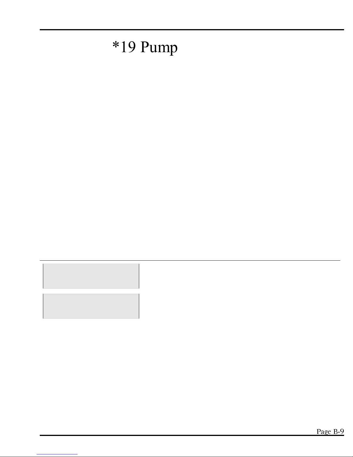
MODEL YB8 PROGRAMMING SECTION
*19 Pump Tube Utilities
*19 resets the tube life pump count. A peristaltic units ability to operate and perform to specifications, such as
transport velocity and lift height is, to a certain extent, det ermined by the medical grade silicone rubber pump
tubing used in the system. T he characteristics of the tubing change as it wears. It becomes less resilient, less
able to maintain its shape, develops pinch points on the outside edge of the tube, and as such is not capable of
the performance it had when it was new. T o maintain optimum performance, it is necessary to monit or the
wear on the tube. *19 does this by enabling the operator to set a maximum number of pump revolutions, the
tube currently in use, will be allowed to withstand. T his, in effect, determines the tube’s useful life. Manning
recommends not exceeding 1,000,000 pump counts for a singular tube as, by this time, there is risk that the
tubing could fail causing a variety of problems. *19 should be used every time the pump tubing is changed.
The user will be alerted to change the tubing, when the tubing reaches the number of counts set. The warning
will appear, every time the user executes a Program Mode, by pressing <START>. S ince all programs are
initiated by pressing <START> the warning will always appear, if a ppropriate, before the program is initiated.
This allows the user the opportunity to exit the program and change the tubing. Once the tubing is changed,
the user can re-enter the program and begin sampling.
When the pump tubing is to be changed, t he user will enter into *19 Mode, just like entering any of the other *
Modes. The sampler will prompt the operator to clear the current pump count by pressing 1, or to maintain
the current count by pressing 0. It is advisable to reset the pump counts when changing the tubing so an
accurate accounting of the number of revolutions, the tube in the pump has experienced, can be obtained. At
this juncture the user will be asked to enter a number for the tube life warning which represents the number of
revolutions the current tube will be allowed to accumulate before a warning is issued. Once entered, the
system will return to the sampler ready prompt and the system will be ready to program.
Display on LCD Explanation
SAMPLER READY
04/30 04:30:02
ENTER * MODE?
__ __ 04:30:02
This display shows the sampler is ready to program. I t displays the
current time. From here the user can enter any TIME, FLOW, or *
Mode. Press the * key to access the * Mode.
Prompts the user to enter either a program or a * Mode. Press 19
and <ENTER> to proceed.
April 1999/Manning Environmental Inc.
3DJH%
Page 42

PROGRAMMING SECTION MODEL YB8
0=MAINTAIN 1=CLEAR
__ 04:30:02
TUBE LIFE WARNING?
__ __ __ __ 04:30:02
This prompt is asking the user to determine how the system will
handle the current accumulation of revolutions:
0 - Maintains the current revolution count. This is useful if the
operator wishes to increase the number of revolutions the current
tubing can accumulate before a tube life warning is issued. For
example, assume the current tubing has 200,000 revolutions. The
operator really wants the warning to come on at 400,000. The 0
key would be pressed instead of 1 to maintain the history the
tubing has already generated. The user would then enter 0400
(for 400,000) at the TUBE LIFE WARNING prompt (see
below).
1 - Resets the current revolution count. This is necessary if the user
is going to be placing brand new tubing into the system. With the
counter reset the user knows exactly how many counts it will take
for the sampler to issue a warning to change the tubing.
Enter the maximum number of counts the tubing will accept before
the sampler issues a pump tube warning. T he number entered is in
terms of thousands (in other words it adds 3 0’s to the end of the
number entered) so if 0500 is entered, the sampler would see it as
500,000. Entering 4000 equals 4,000,000 and 0060 would be
60,000, etc. The sampler will t hen issue a tube life warning when the
pump revolutions meet or exceed the set number of pump counts
entered in *19.
3DJH%
April 1999/Manning Environmental Inc.
Page 43
MODEL YB8 PROGRAMMING SECTION
*91 Data Logging
* 91 is the data logging function for the Manning Environmental Inc. sampler family. T he data logging
function is always active, and will continuously record event s and sampler activities as they occur. T he system
performs a bound checking function on entries. This ensures that entries which exceed the limits placed in the
system are not accepted. If this happens a EEEE will appear on the display. T he user simply presses
<CLEAR> to remove the EEEE and is then able to continue to enter numbers. The unit holds up to 512
entries in battery backed RAM, so in case of power loss the unit will not loose recorded events. If a 513
ent ry occurs, the unit will display a LOG FULL message and that entry and subsequent events and activities
will not be recorded until the log is cleared. The unit will display the collect ed information upon the 2 line by
20 character backlighted LCD display. The data is displayed in a coded format so the maximum amount of
information is available on the screen. The codes are explained in the view menu. *91 can only be entered
from the SAMPLER READY prompt. The user can reach this screen from any location by pressing
<RESET> <RESET>.
Display on LCD Explanation
th
SAMPLER READY
04/30 04:30:02
ENTER * MODE?
__ __ 04:30:02
ID=1 VIEW=2 EXIT=3
DOWNLOAD=4 CLEAR=5
ENTER MENU SELECTION
__ __ 04:30:02
This display shows the sampler is ready to program. I t displays the
current time. From here the user can enter any TIME, FLOW, or *
Mode. Press the * key to access the * Mode.
Prompts the user to enter either a program or the configuration
function. Press 91 and <ENTER> to view the data logging menu.
This menu shows the opt ions available in the data logging menu. I t is
displayed momentarily (3 seconds) before the select ion menu is
brought up.
ID Menu -Allows the user to set Site ID information.
VIEW Menu - Allows the user to review logged data.
EXIT Menu - Takes the user out of the Data logging menu and back
to the Sampler Ready prompt by executing a warm start.
DOWN LOAD Menu - Downloads data to a printer, DTU, or PC.
CLEAR Menu - Clears all logged data, except Site ID, from memory.
Enter the number coinciding with menu to be accessed and press
<ENTER>. T he following sections will explain each of the submenus:
April 1999/Manning Environmental Inc.
3DJH%
Page 44

PROGRAMMING SECTION MODEL YB8
ID Menu
The ID menu allows the user to identify a site at which the events have been logged and a corresponding date
associated with the events at that site. This is represented by a 4 digit number which the user enters in the ID
Menu (see below). The system only allows for one site ID at a time. For example, the user enters 1234 as a
site ID number and logs 100 samples at that site. Later the sampler was moved to a different site. If the
operator enters a new site ID number (5678), the original site ID (1234) will be overwritten with the new sit e
ID number (5678). The operator should download the data before changing site ID numbers in this scenario.
ENTER MENU SELECTION
__ __ 04:30:02
ENTER 4 DIGIT ID #
__ __ __ __ 04:30:02
ENTER MONTH MM#
__ __ 04:30:02
ENTER DAY DD #
__ __ 04:30:02
ENTER YEAR YYYY #
__ __ 04:30:02
At this prompt input a 1 and press <ENTER>
The user enters a 4 digit number that corresponds to the site at which
the samples will be taken. O nly one site number can be used at a
time. Entering a new site number, overwrites all stored site numbers.
This display asks the user to enter the current month in 2 digit format.
For example 03 = March, 11 = November, etc...
The user enters the 2 digit number corresponding to the current day.
The first day of the month being 01, the last being 30 or 31.
The operator enters the current year in 4 digit format.
View Menu
The view menu allows the user to review logged events and activities. T he information recorded is not limited
to sampling events. Activities such as power failure, warm starts, cold starts, etc.. are also recorded to allow
the operator a fuller and more comprehensive understanding of the activities of the unit. The information in
3DJH%
April 1999/Manning Environmental Inc.
Page 45

MODEL YB8 PROGRAMMING SECTION
the VIEW menu is shown in coded format to allow the maximum amount of information to be displayed in the
smallest amount of space.
TIME Twenty four hour clock in HH:MM:SS format.
EVENT # An "E" marks the beginning of information related to Event # and is separated from
the Time by a comma. The event number represents the sequential order of the
events that have been logged since the operator last pushed <START>. For example
E001 would be the first logged event with E512 being the last since the unit logs a
maximum of 512.
BOTTLE # Preceded by a "B", the Bottle # is separated from the Event # by a comma. Bottle
number indicates the Bottle that the sample was placed into.
SAMPLE # This is the first entry on the 2nd line of the display. It is indicated by an "S".
TRIGGER The trigger code shows the operator what triggered or initiated the sample to be
CODES taken. The following shows the letter corresponding to the sample trigger:
TI = Time Interval TO = Time Override
CC = Contact Closure AL = Analog Level
AF = Analog Flow RD = Rising Delta
FD = Falling Delta TC = Test Cycle (In a program mode)
TY = Test Cycle (Not in a program mode)
RESULT CODES The result code indicates whether the unit was successful or unsuccessful in
collecting the sample. I f the sampler was successful, the unit will indicate this with a
NE. I f t he unit did not collect the sample either a BF or NF will be displayed. T he
codes are as follows:
NE = No Error NF = No Fluid
BF = Bottle Full
ACTIVITY LOG The unit also logs information about non sampling events such as power failures,
start sequences, reset occurrences, etc.. This data is displayed in a different format
than the event entries. You are simply shown the time, in twenty four hour format,
and the activity (in this example START):
16:04:44, START
Each time the particular activity is executed (in this case START), the information
will be stored in the log. This also applies to reset’s, power failures, etc... The
storage of this information increases the users ability to understand the sampling
events and how other activities might have effected the sampling program.
April 1999/Manning Environmental Inc.
3DJH%
Page 46

PROGRAMMING SECTION MODEL YB8
DATE STAMP The samp
stamping occurs in 3 instances:
A. When a program is started
B. When <RESET> <RESET> is executed
C. When midnight occurs
The purpose of the date stamp is to allow the operator to know when various events
occur and when the happen. The sampler does not log the date with every sample,
instead when midnight occurs the date is stamped and each subsequent event, until
the next occurrence of midnight, are recorded on that date.
ENTER MENU SELECTION
__ __ 04:30:02
# OF EVENTS = __ __ __
04:30:02
ENTER THE START #
04:30:02
ler possesses the ability to date stamp events that are logged. T his
At this prompt input a 2 and press <ENTER>
Shows the operator the number of events recorded. The sampler
holds a total of 512 events. This is a momentary display (3 seconds).
The operator is then prompted to enter the point (event #) at which
they want to begin the display of recorded events. Input the starting
point as a 3 digit number and press <ENTER>
ENTER THE COUNT #
__ __ __ 04:30:02
The user is then prompted to enter the number of events they wish to
view. Input the number of events to be viewed as a 3 digit number
and press <ENTER>. This feature allows the user to view all the
logged events, a section of the logged events (300 to 400 for
example), or a single event.
3DJH%
April 1999/Manning Environmental Inc.
Page 47

MODEL YB8 PROGRAMMING SECTION
ENTER SCROLL SECONDS
__ __ 04:30:02
PUSH THE DISPLAY
KEY FOR NEXT EVENT
To set the scroll seconds, enter a 2 digit number representing the
amount of time, in seconds, you wish the display to show a recorded
event before advancing to the next screen. After inputting press
<ENTER>
The sampler displays recorded events in one of two ways:
A. By entering the scroll seconds, the sampler automatically
advances sequentially through the recorded events, showing each
event for the set number of scroll seconds. T his will continue until
the event entered in the COUNT # is displayed. The sampler will
then return to the ENTER SELECTION prompt within *91.
B. The user can also manually review the logged events, although
scroll seconds st ill have to be entered. T o manually examine the
logged events press <DISPLAY> once for each event to be
reviewed. I f <DISPLAY> is not pressed, the unit will default and use
the entered scroll time to advance the display.
This is a momentary display (3 seconds) to remind the user that they
can manually advance the log review or that t he unit will do it
automatically based on the time set at the scroll seconds prompt.
_ _:_ _:_ _ , E_ _ _ , B_ _
S_ _ _ , _ _, _ _
This display is divided into multiple sections to communicate
information about the logged sample.
st
st
1 section - Time at which the sample was collected.
nd
2 section - Headed by a capital "E", indicates the event number.
rd
3 section - Headed by a capital "B" represents the bottle number.
st
1 section - Headed by a capital "S" indicates the sample number.
nd
2 section - Trigger Codes - This is a 2 letter code that specifies
1 Line
nd
2 Line
what initiated the sample. For a complete list of codes,
refer to page 11 - TRIGGER CODES.
rd
3 section - The last section signifies result code. T his tells the user
whether the sampler was successful or unsuccessful in
collecting a sample and why.
To quit viewing data, simply press <RESET> once. This takes you to
the beginning of the menu selection in the Data Logging menu. The
unit will continue to show the events either based on the scroll time or
by pressing <DISPLAY> until the STOP # is reached. At this point
the unit will return the operator to the ENTER SELECTION prompt.
April 1999/Manning Environmental Inc.
3DJH%
Page 48
PROGRAMMING SECTION MODEL YB8
Exit Menu
This menu allows the user to exit back to the SAMPLER READY prompt from which other programs or
functions can be entered. The only other way to exit the data logging menus is to press <RESET> .
However, t his will be recorded as an activity, whereas using the exit menu will not.
ENTER MENU SELECTION
__ __ 04:30:02
At this prompt input a 3 and press <ENTER>. T he unit will execute
a warm start and return to the SAMPLER READY prompt.
Download Menu
The download menu is intended to allow the operator to make either a hard copy (by sending the information
to a printer) or an electronic copy (by sending the information to a PC or a Data Transfer Unit). The
information is in ASCII format and is comma delimited for easier interface with commercially available
spreadsheet programs. The Baud Rate is fixed at 9600 with 8 bits no parity and 1 stop bit. The download
menu is identical to the VIEW menu. The only difference is that when the data is reviewed, it is also being
downloaded to the device of choice.
ENTER MENU SELECTION
__ __ 04:30:02
# OF EVENTS = __ __ __
04:30:02
At this prompt input a 4 and press <ENTER>
Shows the operator the number of events recorded. The sampler
holds a total of 512 events. This is a momentary display (3 seconds).
ENTER THE START #
04:30:02
ENTER THE COUNT #
__ __ __ 04:30:02
The operator is then prompted to enter the point (event #) at which
they want to begin the display of recorded events. Input the starting
point as a 3 digit number and press <ENTER>
The user is then prompted to enter the number of events they wish to
view. Input the number of events to be viewed as a 3 digit number
and press <ENTER>. This feature allows the user to view all the
logged events, a section of the logged events (300 to 400 for
example), or a single event.
3DJH%
April 1999/Manning Environmental Inc.
Page 49

MODEL YB8 PROGRAMMING SECTION
ENTER SCROLL SECONDS
__ __ 04:30:02
PUSH THE DISPLAY
KEY FOR NEXT EVENT
To set the scroll seconds, enter a 2 digit number representing the
amount of time, in seconds, you wish the display to show a recorded
event before advancing to the next screen. After inputting press
<ENTER>
The sampler displays recorded events in one of two ways:
A. By entering the scroll seconds, the sampler automatically
advances sequentially through the recorded events, showing each
event for the set number of scroll seconds. T his will continue until
the event entered in the COUNT # is displayed. The sampler will
then return to the ENTER SELECTION prompt within *91.
B. The user can also manually review the logged events, although
scroll seconds st ill have to be entered. T o manually examine the
logged events press <DISPLAY> once for each event to be
reviewed. I f <DISPLAY> is not pressed, the unit will default and use
the entered scroll time to advance the display.
This is a momentary display (3 seconds) to remind the user that they
can manually advance the log review or that t he unit will do it
automatically based on the time set at the scroll seconds prompt.
_ _:_ _:_ _ , E_ _ _ , B_ _
S_ _ _ , _ _, _ _
This display is divided into multiple sections to communicate
information about the logged sample.
st
st
1 section - Time at which the sample was collected.
nd
2 section - Headed by a capital "E", indicates the event number.
rd
3 section - Headed by a capital "B" represents the bottle number.
st
1 section - Headed by a capital "S" indicates the sample number.
nd
2 section - Trigger Codes - This is a 2 letter code that specifies
1 Line
nd
2 Line
what initiated the sample. For a complete list of codes,
refer to page 11 - TRIGGER CODES.
rd
3 section - The last section signifies result code. T his tells the user
whether the sampler was successful or unsuccessful in
collecting a sample and why.
The unit will begin to scroll through the entries one at a time either
based on the default or on the user pressing the <DISPLAY> key.
The information being displayed is also being sent to the data
collection device attached to the sampler (i.e. printer, PC, DTU).
April 1999/Manning Environmental Inc.
3DJH%
Page 50
PROGRAMMING SECTION MODEL YB8
Clear Menu
The sampler is capable of holding up to 512 events or activities in memory. Once the databank is filled, the
unit will not store any additional information until the event log is cleared. O nce the log has been cleared t he
information that had been stored there is permanently erased. If the information is critical please review the
DOWNLOAD menu above for information on how to save the logged events and activities in either electronic
format or hard copy.
ENTER MENU SELECTION
__ __ 04:30:02
CLEAR LOG DATA
NO = 1 YES = 2 04:30:02
CLEAR?? NO = 1 YES = 2
04:30:02
At this prompt input a 5 and press <ENTER>
This display is shown momentarily to orient the user t o the upcoming
menu selection.
Enter your selection at the prompt:
1 This does not clear the data and will take you back to the
ENTER SELECTION prompt.
2 This will clear all data. I f there is any data that needs to be
retained, make sure a backup exists. Once the data has been
deleted it is unrecoverable. After the data is cleared, you will
be taken back to the ENTER SELECTION prompt.
*14 Clear Log Data
* 14 Clear Log Data option allows the operator to clear the logged data without entering the *91 data logging
program. This selection does not give the user the opportunity to back-out of the clearing of the log. This is
an immediate and unalterable erasure. T he *14 clear data unlike the *91 clear data is accessible from the
SAMPLER READY prompt
SAMPLER READY
04/30 04:30:02
This display shows the sampler is ready to program. I t displays the
current time. From here the user can enter any TIME, FLOW, or
* Mode. Press the * key to access the * Mode.
ENTER * MODE?
__ __ 04:30:02
CLEARING LOG DATA
Prompts the user to enter either a program or the configuration
function. Press 14 and <ENTER> to erase the logged data.
The menu shows the log being cleared. The log is now clear. The
data that was contained within the log is now erased and is
unrecoverable.
SAMPLER READY
04/30 04:30:02
The unit returns to the SAMPLER READY prompt awaiting further
action.
3DJH%
April 1999/Manning Environmental Inc.
Page 51

MODEL YB8 PROGRAMMING SECTION
Analog Option Programming
This section explains how to program the sampler if the unit has the optional analog controller. If it was not
ordered, it is not necessary to read this section. The analog option allows the sampler to accept an analog
signal (4-20mA) from an external device.
When using any of the analog programming Modes (*05,*06, *09, *11, and *13), the sampler will p rompt the
user to enter an upper and a lower limit. T hese limits can refer to flow or level depending on the program.
The limits are important because of the Analog to Digital converter in the YB8. The converter allows an
analog signal to be divided into 256 (0 to 255) divisions which digitizes the signal. The lower limit will
correspond to the lowest signal level (4mA in 4-20mA, etc.) sent from the external
device. T he higher limit will correspond to t he highest signal level ( 4-20mA) sent from the external device.
T he difference between the lower limit and the higher limit is the span.
The processor divides the span into 256 evenly spaced steps.
For example, with a 4-20mA signal, if yo u set the lower limit to equal 4 ft and the upper limit to equal 44 feet
the following values would automatically be assigned to each:
Analog Signal Level A/D Digital Value
4mA 4ft. 0
8mA 14ft. 63
12mA 24ft. 127
16mA 34ft. 180
20mA 44ft. 255
Totalizing
When the volts or amps of a signal vary, corresponding to a flow, then the signal can be used to totalize the
flow. Each time the analog signal is read, a value is obtained that can be converted into a flow. For example,
(using a 4-20mA signal) when the analog signal is 12mA, then we know that the flow rate is half of the total.
If maximum flow is 100 and minimum is 0, then the flow rate is 50. The volume units of the number are
determined by the volume units of the maximum and minimum flows. I f they are in liter then the flow is in
liters, if t hey are in gallons then the flow is in gallons. Flow is volume per unit time, and though t he volume
unit can be anything the time units cannot. Except for 1 condition the flow unit should be volume unit per
minute (gallon/min, L/min, etc), and the interval to check the analog signal should be 1 minute. The exception
is when the sampling sequence (time to take and deposit a sample) takes longer than 1 minute. In this case,
the time interval between analog signal checks must be increased. When the time interval between analog
signal checks is greater then 1 minute, the volume that triggers a sample must be divided by the value of the
time interval to function properly.
April 1999/Manning Environmental Inc.
3DJH%
Page 52
PROGRAMMING SECTION MODEL YB8
*08 Analog Display Routine
The analog display routine allows the operator to display the analog signal received from an external meter
(level, flow pH, etc.). This routine can be used while the sampler is being installed, connected to a flow meter,
or to check the calibration of the sampler’s analog to digital converter.
The program is started by entering <*08> at the “SAMPLER READY” prompt. The analog value will be
displayed in three formats: 1) As a digital value (0 to 255); 2) As a DC voltage (1 to 5 VDC); and 3) in
milliamps (4.0 to 20.0 mA). T he program will continue to loop until reset by the operator pressing the
<RESET> key twice. The analog input signal can be varied while the program is running and the display will
change accordingly.
The sampler’s analog routine can be calibrated by inputting a known milliamp signal or attaching a variable
voltage source across the analog input terminals.
ANALOG VALUES TABLE
TABLE A1
mA DC VOLTS DIGITAL
VALUE
4.0 1.00 000
5.0 1.25 015
6.0 1.50 031
7.0 1.75 047
8.0 2.00 063
9.0 2.25 079
10 2.50 095
11 2.75 111
12 3.00 127
13 3.25 143
14 3.50 159
15 3.75 175
16 4.00 191
17 4.25 207
18 4.50 223
19 4.75 239
20 5.00 255
Table A1 is a conversion table for the analog values. For example, if a voltage of 3.00 volts is placed across
the analog input terminals the sampler should display 12 mA, 3.00 VDS and a digital value of 127. The analog
input circuit is designed with a precision 250 ohm resistor across the input terminals. When an mA analog
signal is input the current flows through the 250 ohm resistor generating a voltage drop proportional to the
current flow. At 12 mA the voltage drop is .012x250 = 3.00 volts. The three volts is converted into a digital
value 127. When a three volt signal is placed across the analog input terminals it generates a current flow
according to ohms law of I = 3/250 = .012 mA.
3DJH%
April 1999/Manning Environmental Inc.
Page 53

MODEL YB8 PROGRAMMING SECTION
Constant current sources are not common. However, batteries of known voltages are readily available; thus,
using a voltage source to calibrate the sampler is useful.
A 4-20 mA source can be calibrated by placing a 250 ohm resistor in the loop and measuring the voltage drop
across the resistor with a voltmeter. Table A1 can be used to interpolate the corresponding MA signal or
Ohms law (V/R = 1) can be used to calculate the mA signal. If the voltage is 4.25, then the mA signal is
4.25/250 = .017 amps or 17 mA.
April 1999/Manning Environmental Inc.
3DJH%
Page 54

PROGRAMMING SECTION MODEL YB8
Add-On Programming Functions
Multiple Bottles per Sampling Event
Multiple Bottles per Sampling Event is not a stand alone function but works in conjunction with TIME,
FLOW and certain * Modes (*02, *04, *05, *06, *09) to expand the capabilities of the sampler. T his option
places 1 sample in from 2-24 bottles in rapid succession during 1 sampling event (such as a contact closure or
a time interval). To use Multiple Bottle per Sampling Event, the user selects the mode of choice - a TIME,
FLOW, or * Mode. After entering the required information, the PUSH START/OPTIONS prompt will
appear on the display. At this cue press <MULTI BOTTLE> and enter the number of bottles into which 1
sample should be placed, in rapid succession. For example, Multiple Bottles per Sampling Event would be
used if a sample is to be taken every 100,000 gallons, and 1 sample is to be placed in 5 different bottles each
time there is a contact closure. The unit would start the sampling sequence after it had received a contact
closure. It would draw and place 1 sample in the first bottle, immediat ely move to the second, draw and place
1 sample in that bott le, immediately move to the third, draw and place 1 sample in that bottle and so on until it
had deposited 1 sample in the specified number of bottles (in this example 5).
Display on LCD Explanation
SAMPLER READY
04/30 04:30:02
PUSH START/OPTIONS
04:30:02
BOTTLES PER SAMPLE?
__ __ 04:30:02
PUSH START/OPTIONS
04:30:02
FLOW MODE
__ __ __ __ 04:30:02
This display indicates the sampler is ready to program. Multiple
Bottles per Sampling Event is not a stand alone program. It works in
conjunction with FLOW, TIME, and certain * Modes. In this
example <FLOW> was pushed as the mode of choice.
At this prompt the user selects Multiple Bottles per Sampling Event,
by pressing <MULTI BOTTLE>.
Input the number of bottles into which 1 sample will be placed in
rapid succession during a sampling event and press <ENTER>.
At this point, simply press <START>. N OTE: Multiple Bottles per
Sampling Event and Multiple Samples per Bottle cannot be select ed
simultaneously. They are mutually exclusive options.
The unit is now waiting for a contact closure to initiate the sample
sequence.
3DJH%
April 1999/Manning Environmental Inc.
Page 55
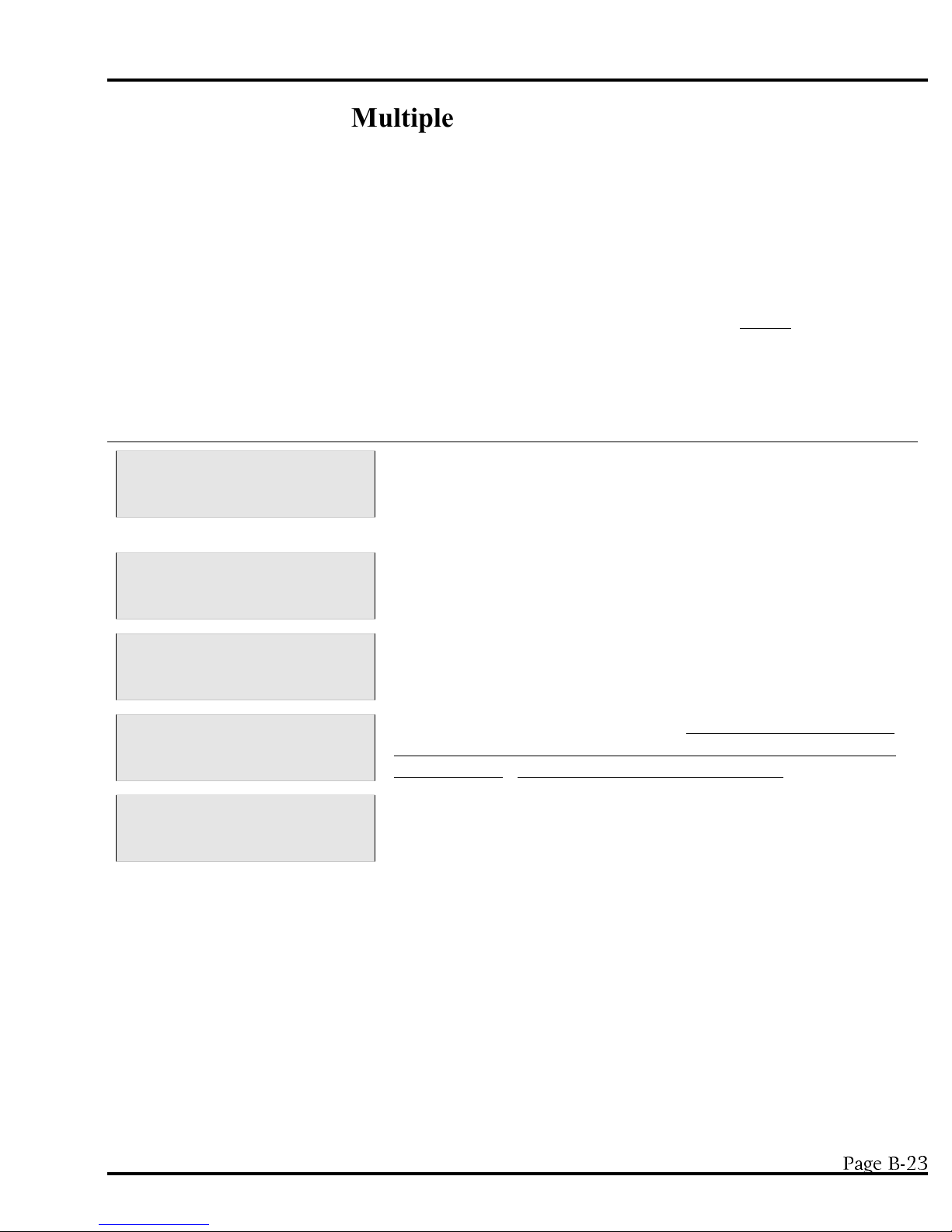
MODEL YB8 PROGRAMMING SECTION
Multiple Samples per Bottle
Multiple Samples per Bott le is not a stand alone function but works in conjunction with other TIME, FLOW
and certain * Modes (*02, *04, *05, *06, *09) to expand the capabilities of the sampler. T he sampler places
from 2 to 99 samples in each bottle. In order to use Multiple Samples per Bottle, the user selects the mode of
choice - a TIME, FLOW, or * Mode. After entering the required information, the PUSH START/OPTIONS
prompt will appear on the display. At this cue press <MULTI SAMPLE> and enter the number of samples
per bottle. For example, if Flow Mode were being used and Multiple Samples Per Bottle is set at 5, each time
an event occurred, such as a contact closure or the end of a time interval, the sampler would place a sample in
a bottle. When the next event occurs, the sampler would place another sample in the SAME bottle, until 5
samples had been placed in that bottle. It would then advance the spout to the next bottle in sequence. The
sampler would then repeat the process above for the current bottle. This would continue until the total
number of bottles the unit is configured for (set in *99) have received their allocation of samples.
Display on LCD Explanation
SAMPLER READY
04/30 04:30:02
PUSH START/OPTIONS
04:30:02
SAMPLES PER BOTTLE?
__ __ 04:30:02
PUSH START/OPTIONS
04:30:02
FLOW MODE
__ __ __ __ 04:30:02
This display indicates the sampler is ready to program. Multiple
Samples per Bottle is not a stand alone program. It works in
conjunction with FLOW, TIME and certain * Modes. In this
example <FLOW> was pushed as the mode of choice.
At this prompt the user selects Multiple Samples per Bottle, by
pressing <MULTI SAMPLE>.
Input the number of bottles into which 1 sample will be placed during
a sampling event and press <ENTER>.
At this point, simply press <START>. N OTE: Multiple Bottles per
Sampling Event and Multiple Samples per Bottle cannot be select ed
simultaneously. They are mutually exclusive options.
The unit is now waiting for a contact closure to initiate the sample
sequence.
April 1999/Manning Environmental Inc.
3DJH%
Page 56
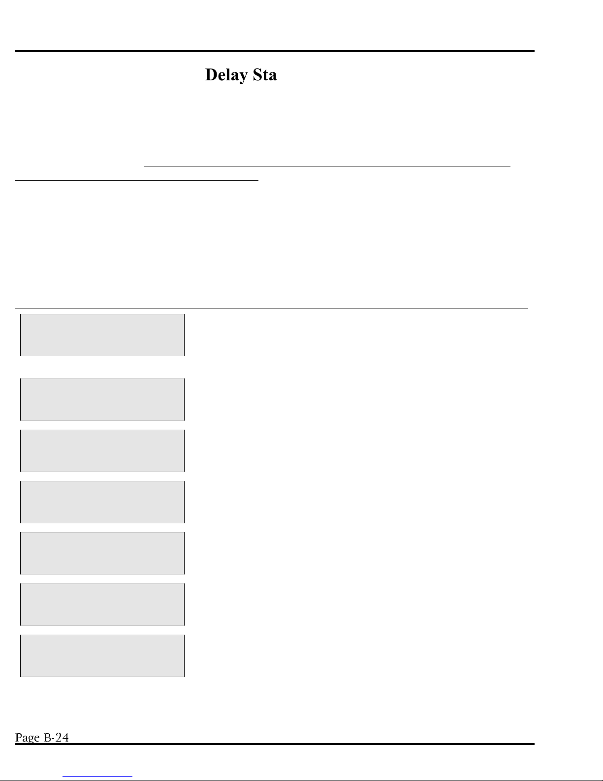
PROGRAMMING SECTION MODEL YB8
Delay Start - Time
Delay Start - Time works in conjunction with TIME and certain * Modes to expand the capabilities of the
sampler. It is not a stand alone program and cannot be used with * Start, FLOW MODES, *01, *05, *06,
*09, *11, *12, or *13. Delay Start - Time works by allowing the user to add a period of time to the beginning
of a TIME or * Mode to delay the start of the program. This time period must elapse before the program can
begin to operate. NOTE: S ome programs already have a Delay Start - Time in the program negating the
user’s ability to add an additional Delay Start - Time. The user selects the mode of choice and enters the
required information. T he PUSH START/OPTIONS prompt will then appear on the display. At this cue
press <DELAY START> and enter the amount of time (in HH:MM format) the sampler is to wait before
beginning t he program. O nce the Delay Start has elapsed, the program will start. For example, if t he sampler
were programmed with a 9.5 hour Delay Start - Time and a 1.5 hour Time Interval, the sampler would wait
for 11 hours until the first sample is taken, (9.5 hours of Delay Start - Time and 1.5 hours for the Time
Interval). The sampler would then take a sample every 1.5 hours until all of the bottles (set in *99) each have
a sample placed in them or a bottle full condition occurs.
Display on LCD Explanation
SAMPLER READY
04/30 04:30:02
ENTER INTERVAL TIME
__ __:__ __ 04:30:02
PUSH START/OPTIONS
04:30:02
ENTER DELAY START
__ __:__ __ 04:30:02
PUSH START/OPTIONS
04:30:02
DELAY START TIME
__ __:__ __ 04:30:02
This display indicates the sampler is ready to program. D elay Start Time is not a stand alone program. It works in conjunction with
TIME, and certain * Modes. In this example <TIME> was pushed as
the mode of choice.
Enter the time interval as a 4-digit number (HH:MM format) and
then press <ENTER>.
The program can then be started by pressing <START> or other
functions can be added on such as Delay Start - Time. In this
example <DELAY START> was pressed.
This display prompts the user to enter a Delay Start time (in HH:MM
format). T his is the amount of time the sampler is to wait before
starting the regular program (in this case TIME mode).
The sampler is now ready to begin operation. Press <START> to
begin the Delay Start countdown, or add other options such as
Multiple Samples per Bottle or Multiple Bottles per Sampling Event.
This display shows the time remaining on the Delay Start.
TIME TO NEXT SAMPLE
__ __:__ __ 04:30:02
3DJH%
Once the Delay Start has counted down to zero, the Interval Time
entered earlier will begin counting down. This display shows the
time left to take a sample. As mentioned above, Delay Start - Time
works with TIME, and certain * Modes.
April 1999/Manning Environmental Inc.
Page 57

*15 - Active Sampling
MODEL YB8 PROGRAMMING SECTION
January 2000/Manning Environmental Inc. Page 24-A
This mode allows the operator to program active sampling periods for each day of the week. The operator
enters the days to sample and an active time period (start time to stop time) for each day that sampling is to
occur. The operator also chooses if the sampler will restart sampling (clears program parameters) or resume
sampling (keep the program parameters from the last active period) when a new active day and time is
started. In order for Active Sampling (*15) to work correctly, the sampler clock must be correctly
set, and a sampling program (TIME, FLOW, *02, *05) must be programmed.
If an end of sequence event (such as a bottle full) occurs before the active sampling period expires, then the
active time period will have no effect. If the active time period expires while a sample is in process the
sample will be completed and no more samples will be taken. After active sampling is set up in Program15,
the operator then programs the sampler with whatever time or flow-paced program is required. During the
active time period of an active day of the week, the sampler collect samples based on the sample program
that is running. At the end of the active time period no more samples are collected until the next active
day/time period.
If Active Sampling is programmed, The right-most position (position 20) on the top line of the LCD display
indicates the Active Sampling status. A blinking “A” indicates that the sampler is in an active time period
and sampling is allowed. A blinking “I” indicates that the sample is in a inactive time period and no
sampling is allowed. If the last active period of the week has passed, the second line of the display indicated
“NO MORE”, meaning that no more sampling will occur that week. A week starts on Monday and ends on
Sunday. Active sampling is turned turn off by entering the Program 15 mode and entering a 0 at the
ACTIVE SAMPLING? prompt.
The major use of the active sampling period will be in industrial monitoring situations where (as dictated by
the EPA) a valid sample period cannot be longer than a specified period of time (i.e., 24 hours), or in
sampling situations were sampling is only required for a certain part of the week (i.e., Thursday 8:00AM
until Sunday 8:00PM).
Display on LCD Explanation
SAMPLER READY
04/30 04:30:02
ENTER PROGRAM #
__ __ 07/30FRI
ACTIVE SAMPLING?
0 04:30:02
This display indicates the sampler is ready to program and
alternately displays the current time and date. Press the * key
to begin programming.
The sampler is now prompting for a star mode to be input. Enter
the numbers which represent the star mode of choice, in this
example 15, and press <ENTER>.
The sampler then asks if Active Sampling is to be turned on. Enter
a “1" and press <ENTER> . To turn off Active Sampling, enter a
“0" and press <ENTER>. If Active Sampling is turned off, the
display will return to the SAMPLER READY prompt.
Page 58

RESTART=0 RESUME=1
MODEL YB8 PROGRAMMING SECTION
January 2000/Manning Environmental Inc. Page 24-B
0 04:30:02
The sampler then prompts for selection of RESTARTING sampling
at the beginning of each active period (enter “0") or RESUMING
sampling at the beginning of each active period (enter “1").
Restarting sampling causes the sampler reset the bottle and sample
count at the beginning of the next active period.
ENTER DAYS OF WEEK
Mo Tu We Th Fr Sa Su
1 2 3 4 5 6 7
Mo Tu Fr
1 2 3 4 5 6 7
Mon. START TIME
__:__ 04:30:50
The display prompts to enter the days of the week that you want to
sample. This information is displayed for only 5 seconds.
The display then changes to numbers on the bottom line which
represent the days of the week (1=Monday, 2=Tuesday, etc.) Press
number key(s) on the keypad that corresponds to the day(s) that you
want to sample.
For each day that was selected as a active sampling day, the name
of the day will appear above its corresponding number on the first
line of the display. If you press the number key of a day that is
active, it will become inactive an the name of the day will
disapp ear f rom the first l ine of the d isplay. Aft er al l th e act ive days
have been selected, press <ENTER> to continue.
For each day that was selected as an active sampling day, the
sampler asks for a start time in HH:MM format. Enter the start
time and press <ENTER>. Enter a start time of 00:00 if you want
sampli ng to sta rt at the beg inning o f the day.
Mon. STOP TIME
__:__ 07/30FRI
The sampler then asks for the sop time in HH:MM format. Enter
the stop and press <ENTER>. Enter a stop time of 24:00 if you
want sampl ing t o continue to the en d of the day.
This step and the previous one are repeated for each day that was
selected t o be an ac tive sam pling da y.
SAMPLER READY A
04:30:02
After the final stop ti me has been en tered, the display will ch ange
to SAMPLER READY. If the present day and time is in an active
sampling period, the display will have a blinking “A” in the upper
right-hand corner. If the present day and time is not in an active
sampling period, the display will have a blinking “I” in the upper
right-hand corner.
Once the active period has been setup using Program
15, you can then enter a sampling program.
Page 59
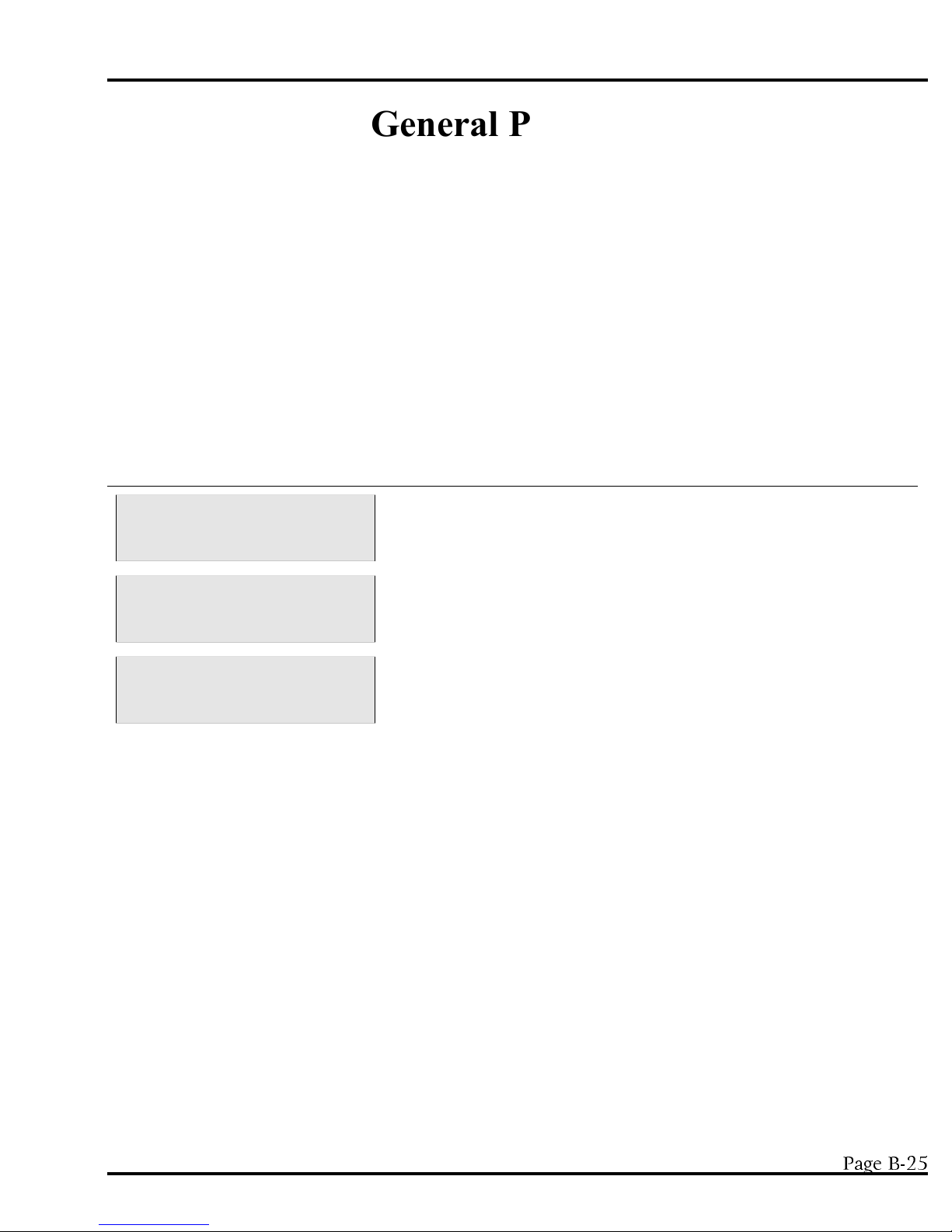
MODEL YB8 PROGRAMMING SECTION
General Programs
Time Mode - * Start
* START is a unique programming mode. It is unlike any other mode in that it automatically programs the
unit to take a sample every hour. Simply press the * key and then <START>. As soon as <START> is
pressed, the sampler begins counting down 1 hour. At the end of that hour the sample sequence will be
initiated. T he sampler will advance the spout, draw 1 sample, and place it in a bottle. The time interval will
reset as soon as the sample cycle start s. A t the end of the second hour the spout will advance and another
sample will be taken and deposited. This will continue until the total number of bottles the unit is configured
for (set in *99) each have 1 sample placed in them or a bottle full condition occurs. The sequence will then be
finished and the unit will stop operation waiting for the same or a new program to be entered. For example, if
the sampler was configured for 24 bottles, the sampler would place 1 sample in each bottle, over a 24 hour
period for a total of 24 samples, and then stop operation.
Display on LCD Explanation
SAMPLER READY
04/30 04:30:02
ENTER * MODE
__ __ 04:30:02
TIME TO NEXT SAMPLE
01:00 04:30:02
This display indicates the sampler is ready to program and displays
the current time. P ress the * key to begin programming.
At the ENTER * MODE prompt, press <START> to begin the *
Start Mode.
The sampler is automatically programmed and the display will show
the time (in HH:MM format) until the next sample.
April 1999/Manning Environmental Inc.
3DJH%
Page 60

PROGRAMMING SECTION MODEL YB8
Time Mode - Single Time Interval
This mode is similar to * START except the user sets the Time Interval instead of having it automatically set
to 1 hour. The user enters a time in HH:MM format from 1 minute to 99 hours and 59 minutes. This time
interval is used to initiate each sampling sequence in this program until the sampler ends its cycle and/or is reprogrammed. A fter the time interval is entered and the program has been initiated by pressing <START>, the
sampler will begin counting down the time interval. When the interval has elapsed, the unit will advance the
spout, draw 1 sample, and place it in a bottle. The timer will reset as soon as the sample cycle starts and will
immediately begin counting down the same time interval again. A fter the interval has elapsed again, the spout
will advance and another sample will be taken and deposited. T his will continue until the total number of
bottles the unit is configured for (set in *99) each have 1 sample placed in them or a bottle full condition
occurs. For example, if the time interval is set for 1 hour 30 minutes, the sampler would count down 1 hour
and 30 minutes, advance the spout, take the first sample, and reset the timer. After another 1 hour and 30
minutes the spout would advance to bottle 2, the sampler would take a sample and reset the timer, etc.
Display on LCD Explanation
SAMPLER READY
04/30 04:30:02
ENTER INTERVAL TIME
__ __:__ __ 04:30:02
PUSH START/OPTIONS
04:30:02
TIME TO NEXT SAMPLE
__ __:__ __ 04:30:02
This display indicates the sampler is ready to program and displays
the current time. P ress <TIME> to begin programming.
Enter the time interval as a 4-digit number (HH:MM format) and
then press <ENTER>.
The program can then be started by pressing <START> or other
functions can be added. In this example, <START> is pressed.
The display will show the time until the next sample.
3DJH%
April 1999/Manning Environmental Inc.
Page 61

MODEL YB8 PROGRAMMING SECTION
THIS PAGE BLANK
April 1999/Manning Environmental Inc.
Page 62
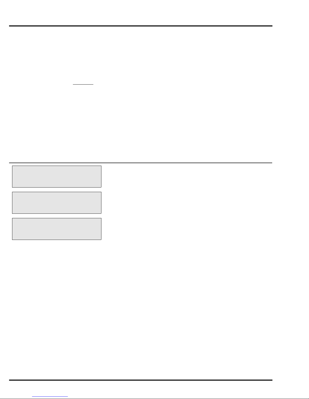
PROGRAMMING SECTION MODEL YB8
Flow Mode
Flow Modes differ from Time Modes in that instead of taking a sample after a time interval has elapsed, the
unit will take samples after receipt of a contact closure from an external device. Whether those contact
closures are based off Flow, pH, Level, ORP, DO, etc. is transparent to the sampler. The unit simply
acknowledges a contact closure was received and that in turn triggers the sample collection process. In
FLOW Mode the sampler does not control totalization, logging, or the meeting of certain parameters, etc. so
they must be done by the external device. Once the parameters have been met, a contact closure will be
output to the sampler. Every time a contact closure is received, the sample collection process is initiated.
The sampler will advance the spout, draw 1 sample and place it in a bottle. It will then wait for the next
contact closure while displaying a running tally indicating the number of samples taken to that point. This
will continue until the total number of bottles the unit is configured for (set in *99) each have a sample
placed in them or a bottle full condition occurs. If either of these two conditions occur, the sampler ends the
program.
Display on LCD Explanation
SAMPLER READY
10:04
PUSH START/OPTIONS
FLOW MODE
__ __ __ __
This display indicates the sampler is ready to program and displays
the current time. Press <FLOW> to begin programming.
The program can then be started by pressing <START> or other
functions can be added. In this example, <START> was pressed.
The sampler is now waiting to accept contact closures to trigger the
sample collection process.
Page B-28
January 2000/Manning Environmental Inc.
Page 63
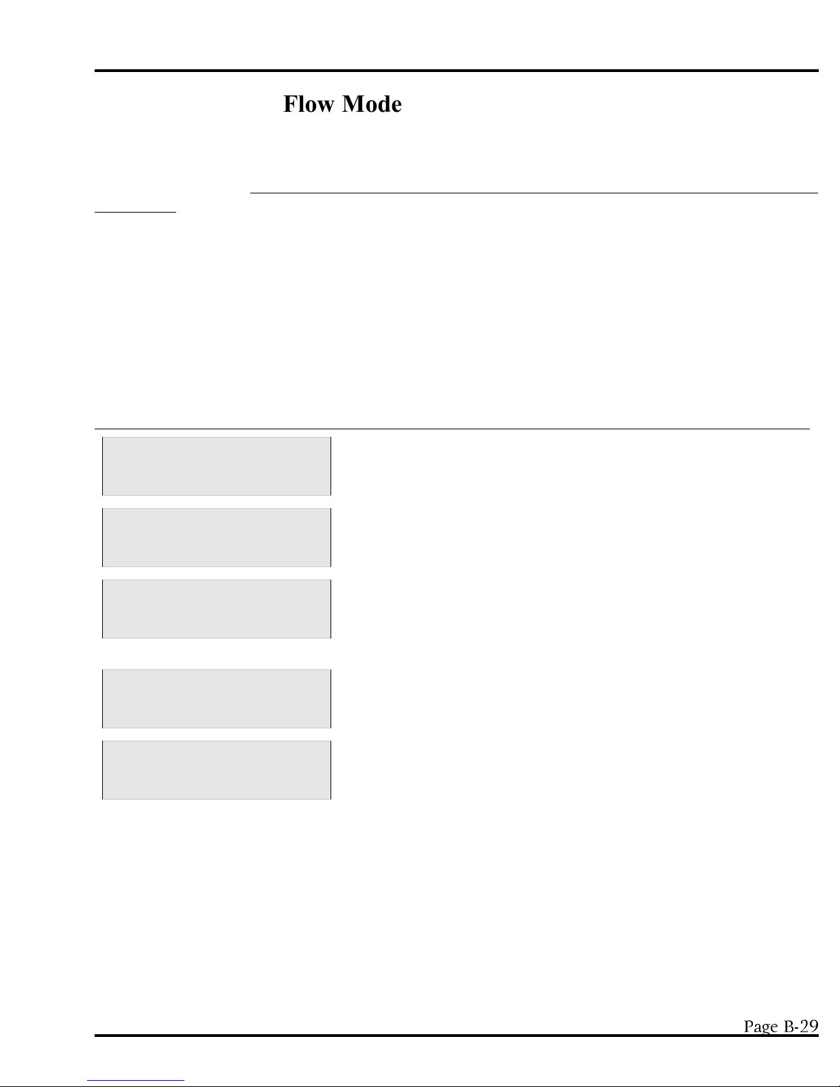
MODEL YB8 PROGRAMMING SECTION
Flow Mode - Pulse Accumulation
FLOW Mode - Pulse Accumulation operates the same as FLOW Mode except instead of taking a sample after
every contact closure, a sample is taken after a set number of contact closures (from 2 - 9,999) have been
accumulated. NOTE: This program uses <DELAY START> for setting the number of contact closures to be
accumulated. T he display will show the number of contact closures the sampler is programmed to accumulate
before taking a sample. Every time a contact closure is received, the sampler will decrease the number needed
on the display by one. This shows how many more contacts have yet to be accumulated before a sample is
taken. Once the set number of contact closures are received, the sampler will advance the spout, draw 1
sample and then place it in a bottle. It will then wait for the next accumulation. This will continue until the
total number of bottles the unit is configured for (set in *99) each have a sample placed in them or a bottle full
condition occurs. If, either of these two conditions occur, the sampler ends the program.
Display on LCD Explanation
SAMPLER READY
04/30 04:30:02
PUSH START/OPTIONS
04:30:02
DELAY IN PULSES?
__ __ __ __ 04:30:02
PUSH START/OPTIONS
04:30:02
FLOW MODE
__ __ __ __ 04:30:02
This display indicates the sampler is ready to program and displays
the current time. P ress <FLOW> to begin programming.
To set the number of contacts to be accumulated in FLOW Mode Pulse Accumulation, press <DELAY START> and then the
<START> button.
The user is now prompted to set the number of contact closures the
sampler will accumulate before taking a sample (2 - 9,999). Until it
is changed or ends its cycle, it will always accumulate the same
number of pulses before taking a sample.
Unless add-on options to the program are desired, press <START>.
This display shows the number of contact closures remaining before a
sample will be taken. A s contact closures are received the sampler
counts down until it reaches 0. It will then take a sample and reset to
accumulate the entered number of contact closures again.
April 1999/Manning Environmental Inc.
3DJH%
Page 64
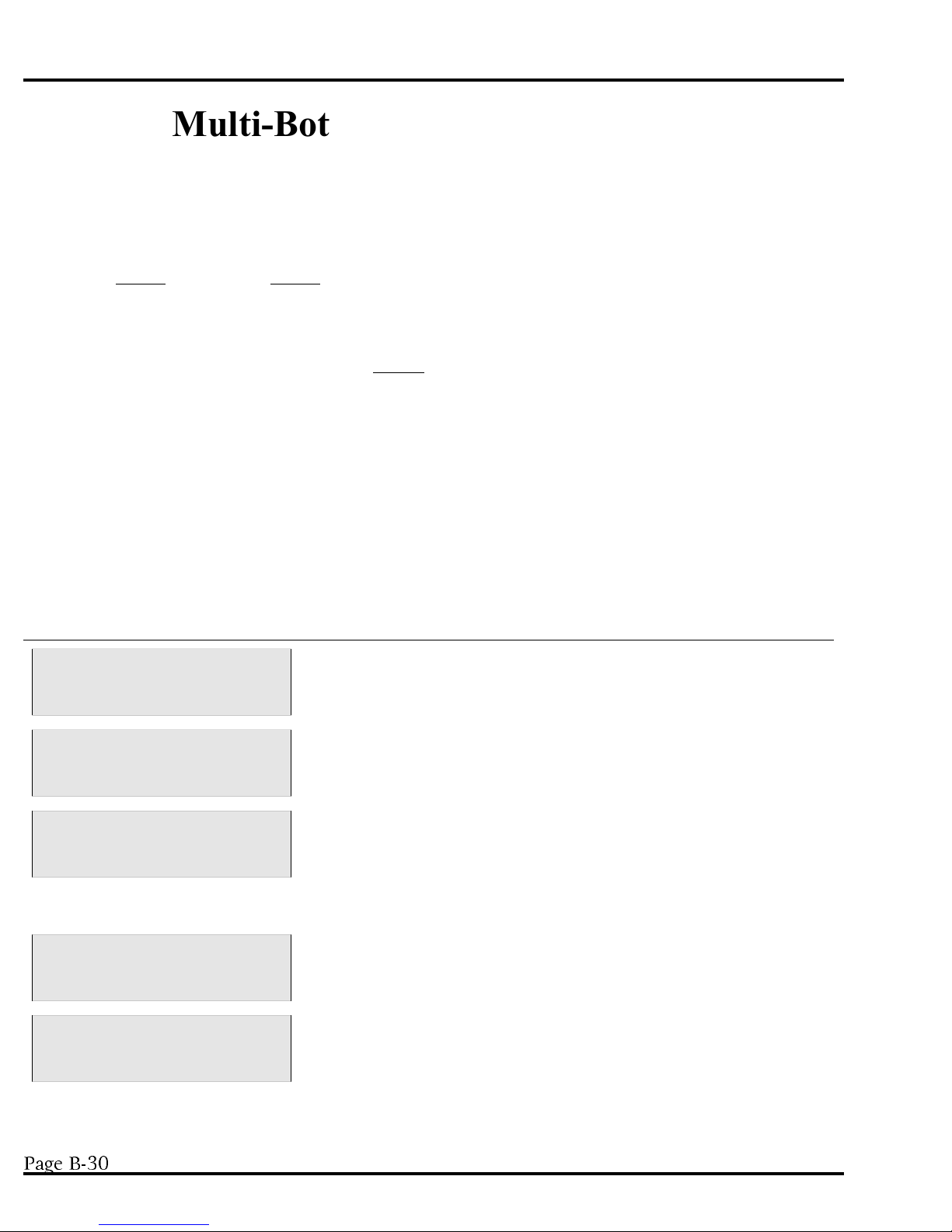
PROGRAMMING SECTION MODEL YB8
Multi-Bottle Sampling Programs
*01 Flow Mode - Independently Timed Spout Advance
The *01 program is used to obtain flow proportional samples over a period of time. Each bottle the sampler is
configured for has a time interval (referred to as a time window) during which it is active. S amples can only
be placed in THAT bottle during THAT a ctive time window. O nce the sampler is programmed, it waits for a
contact closure while counting down the time interval that was set. If it receives a contact closure, while
counting down the Time Interval, a sample sequence will be initiated. T he sampler will advance the spout,
draw 1 sample, and place it in the active bottle. For every contact closure received during the active time
window, the sampler will place 1 sample in the SAME active bottle. Once the first time window has elapsed
(all the time windows have the same time increment), the sampler will begin counting down the second time
window while waiting for contact closures for the next active bottle. This continues until all of the bottles (set
in *99) have at least 1 sample placed in them. A bottle could potentially have more than 1 sample if more
than 1 contact closure is received during the bottle’s active time window. If the sampler has not received a
contact closure by the end of t he active time window the unit will advance the bottle spout and place 1 sample
in the bottle that had most recently been active.
N OTE: There is no overflow protection in this mode. M ake sure that the sample volume
is small enough compared to the flow rate to prevent over-filling.
Display on LCD Explanation
SAMPLER READY
04/30 04:30:02
ENTER * MODE
__ __ 04:30:02
ACTIVE TIME INTERVAL
__ __: __ __ 04:30:02
PUSH START/OPTIONS
04:30:02
FLOW MODE (* 01)
__ __ __ __ 04:30:02
This display indicates the sampler is ready to program and displays
the current time. Press the * key to begin programming.
The sampler is now prompting for a star mode to be input. E nter the
numbers which represent the star mode of choice, in this example 01,
and press <ENTER>.
The sampler then asks for an interval time. This is the amount of
time
(1 min to 99 hours and 59 min) during which the sampler will place
samples in the active bottle. Enter the time in HH:MM format and
press <ENTER>.
If no add-on options are desired, press <START> to begin the
program.
The sampler is now waiting to receive contact closures and is
independently counting down the interval time.
3DJH%
April 1999/Manning Environmental Inc.
Page 65

MODEL YB8 PROGRAMMING SECTION
*02 Flow Mode - Time Interval Override
*02 operates much like basic FLOW mode except a time override is added. The override time ensures a
sample is collected, after a set amount of time has elapsed, if a contact closure has not been
the program has been started the sampler will immediately begin counting down the override time. The
sampler is also concurrently waiting for contact closures. Every time a contact closure is detected the sampler
will advance the spout, draw a sample, and then place it in a bottle. It will then wait for the next contact
closure while displaying a running tally indicating the number of samples collected to that point. If there have
been no contact closures by the end of the override time the user specifies, the sampler will advance the spout,
draw a sample, and then place it in a bottle. The override timer will then reset and immediately start counting
down again while waiting for the next contact closure. T his will continue until the total number of bottles t he
unit is configured for (set in *99) each have their set number of samples placed in them or a bottle full
condition occurs. If either of these two conditions occur, the sampler ends the program.
he unit will take 1 sample per override time interval until all bottles have samples.
received. Once
Display on LCD Explanation
SAMPLER READY
04/30 04:30:02
ENTER * MODE
__ __ 04:30:02
TIME OVERRIDE?
__ __ : __ __ 04:30:02
PUSH START/OPTIONS
04:30:02
FLOW MODE (* 02)
__ __ __ __ 04:30:02
This display indicates the sampler is ready to program and displays
the current time. Press the * key to begin programming.
The sampler is now prompting for a star mode to be input. E nter the
numbers which represent the star mode of choice, in this example 02,
and press <ENTER>.
Input the maximum time the sampler will be allowed to wait to
receive a contact closure, understanding that if the unit has not
received a closure in this time, it will automatically take a sample.
Press <ENTER> after inputing.
If no add-on options are desired, press <START> to begin the
program.
The sampler is now ready to receive contact closures and is
independently counting down the Time Override.
April 1999/Manning Environmental Inc.
Page 66
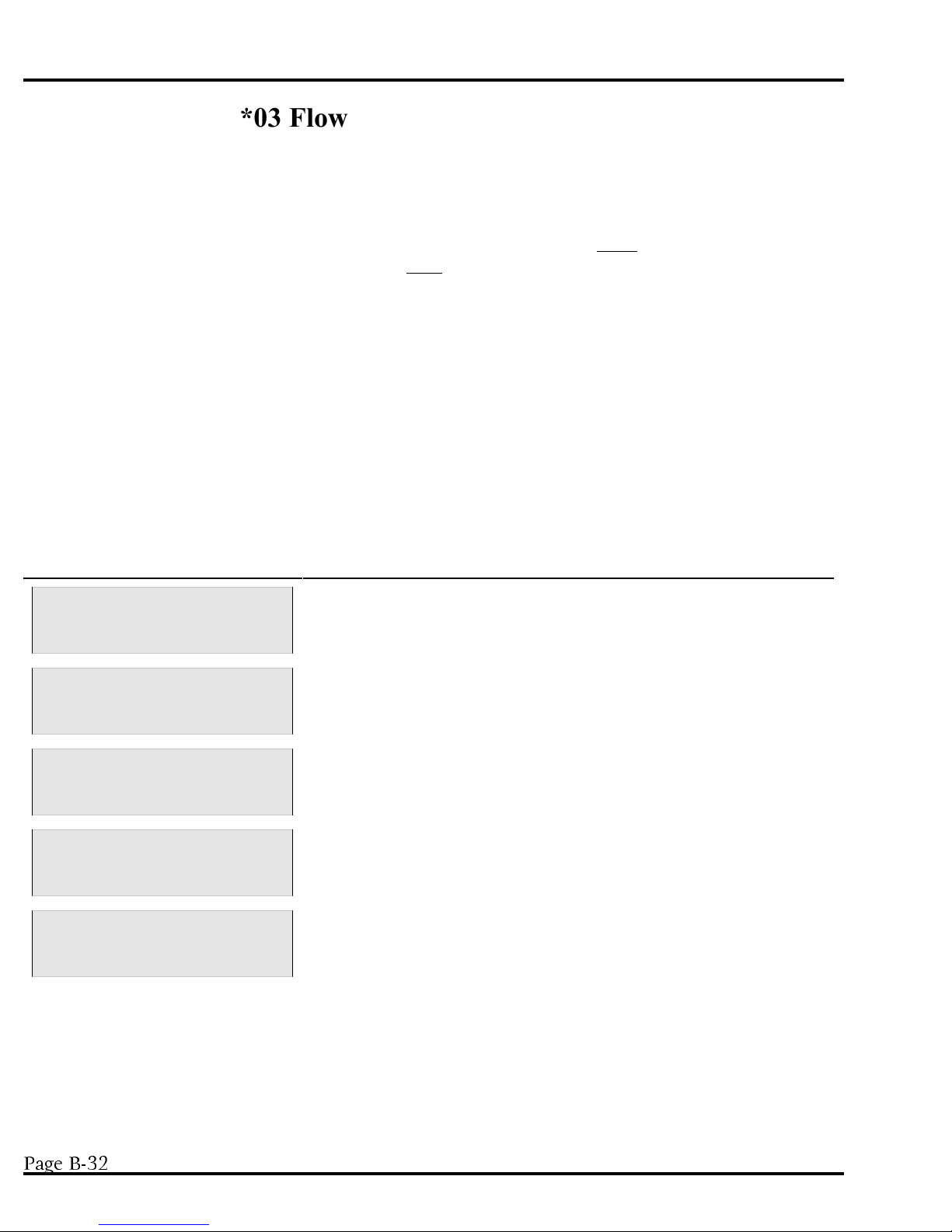
PROGRAMMING SECTION MODEL YB8
*03 Flow Mode - External Event
*03 is used for monitoring intermittent events by combining portions of Flow and Time modes. *03 differs
from regular flow modes based on the way the sampler interacts with the contact closures it receives. In
normal flow mode the sampler receives a momentary closure from an external device, and this initiates a
sampling cycle. In *03 the sampler also initiates a sample cycle based off the initial contact closure it receives.
Once it has received that initial closure, the contact must remain closed for *03 to operate as intended. By the
contact remaining closed, the time portion of the mode is brought into effect and the unit will take samples
based off a user set time interval. For example, assume the user has an external device with a relay that is
normally open. The user sets a high and low trip point within the device. If an event takes place based on the
high or low set point, the unit will send a closure to the sampler. T his causes a sampling cycle to take place.
If the contact does not remain closed, the unit will act as if it w ere programmed for regular flow mode, and
simply take samples each time a contact closure is received. If the relay remains closed, however, the unit will
then start to count down the user set time interval and once that interval has elapsed, take a sample. Each time
the interval elapses, the unit will perform a sampling sequence. T his will continue until the total number of
bottles the unit is configured for (set in *99) each have their set number of samples placed in them or a bottle
full condition occurs. I f the contact opens before either of these two occurrences the sampler will suspend
operation until it once again receives a contact closure that remains closed. After receiving another contact
that remains closed the sampler will begin where it left off from the last contact closure.
Display on LCD Explanation
SAMPLER READY
04/30 04:30:02
ENTER * MODE
__ __ 04:30:02
ENTER TIME INTERVAL
__ __:__ __ 04:30:02
PUSH START/OPTIONS
04:30:02
FLOW MODE (* 03)
__ __ __ __ 04:30:02
This display indicates the sampler is ready to program and displays
the current time. Press the * key to begin programming.
The sampler is now prompting for a star mode to be input. E nter the
numbers which represent the star mode of choice, in this example 03,
and press <ENTER>.
Input a time interval in HH:MM format.
If no add-on options are desired, press <START> to begin the
program. NOTE: DELAY START does not work with *03.
The sampler is now ready to receive contact closures and is
independently counting down the Time Override.
3DJH%
April 1999/Manning Environmental Inc.
Page 67
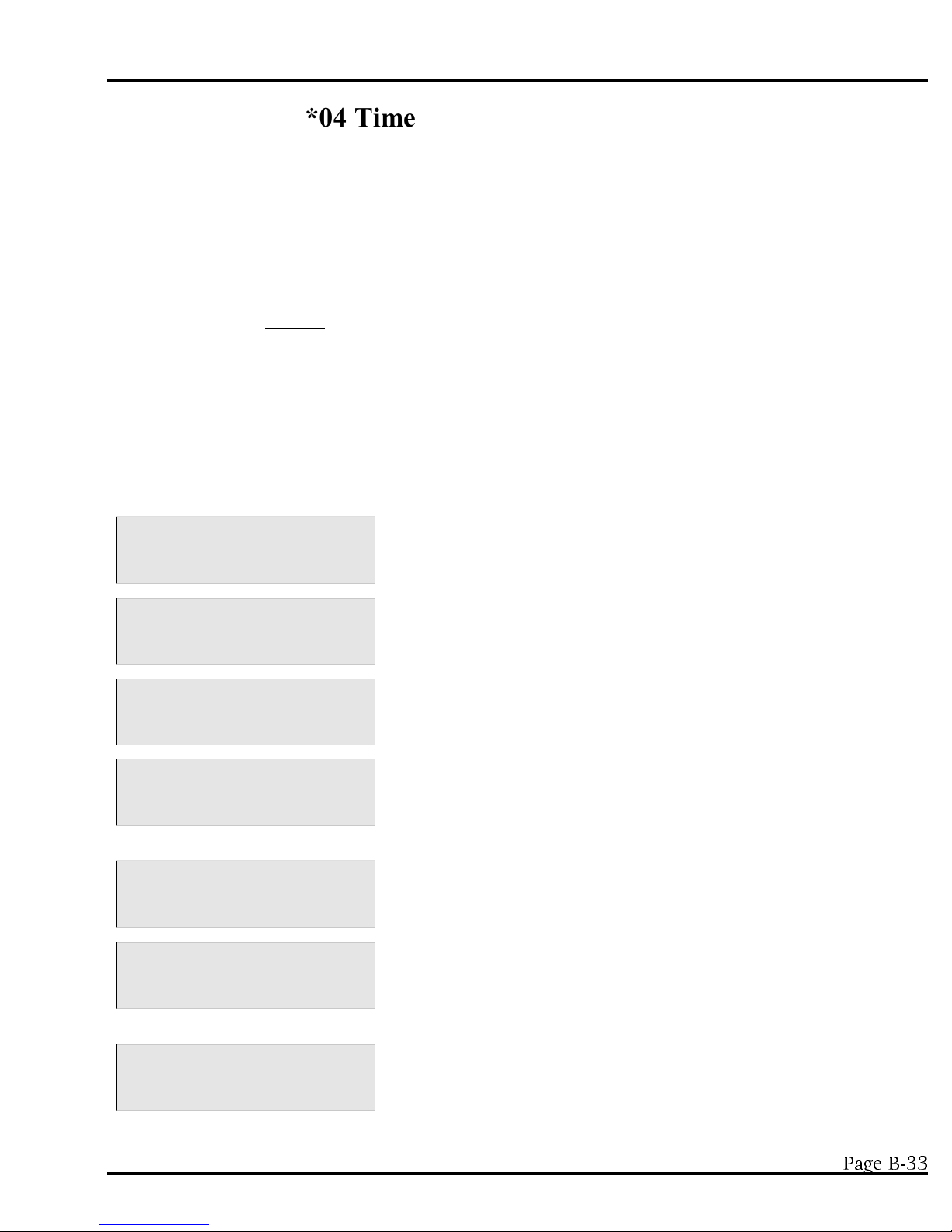
MODEL YB8 PROGRAMMING SECTION
*04 Time Mode - Multiple Intervals
The *04 mode allows programming of up to 12 DIFFERENT non-uniform time intervals (1 min to 99 hours
and 59 minutes). Non uniform time intervals refer to each interval being different from the previous or next
interval. Once an interval is entered, the user is given the option of repeating the interval or entering a new
interval. To repeat the interval, press <ENTER> once for each time the user wants the same interval repeated.
The display will show the COUNT increasing, indicating the same interval is being logged multiple times. An
interval can be the same as a previous interval as long as there is a DIFFERENT interval between them. For
example if 01:00 was entered for the first interval, 02:00 for the second, and then 01:00 was entered again, this
would be counted as THREE different intervals. After the program is initiated, the sampler will begin
counting down the first interval. O nce that interval has elapsed, the unit will start the sample taking sequence
and will immediately start counting down the next interval. T he sampler will draw and place a sample in 1
bottle and then advance the spout. T he sampler will repeat the operation each time an interval expires. The
sampler will continue this pattern until all the intervals entered have expired, the total number of bottles the
unit is configured for (set in *99) each have at least 1 sample placed in them, or a bottle full condition occurs.
Data entry can be ended at any time by pressing the * key.
Display on LCD Explanation
SAMPLER READY
04/30 04:30:02
ENTER * MODE
__ __ 04:30:02
ENTER FIRST INTERVAL
__ __ :__ __ 04:30:02
INTERVAL:1 COUNT: 1
01 :00 04:30:02
INTERVAL:2 COUNT: 1
02 :00 04:30:02
INTERVAL:2 COUNT: 2
02 :00 04:30:02
This display indicates the sampler is ready to program and displays
the current time. Press the * key to begin programming.
The sampler is now prompting for a star mode to be input. E nter the
numbers which represent the star mode of choice, in this example 04,
and press <ENTER>.
The user is prompted to input the first time interval in HH:MM
format. Once the entry is complete press <ENTER>. The sampler
considers this the FIRST time interval.
The display is now indicating it has recorded 1 interval (up to 12
different ones can be entered) and the interval has not been repeated.
In this example the user entered an interval of 1 Hour. The user
must now input a new interval or repeat the current interval.
The user inputs a new interval (0200) representing 2 hours. The
display indicates the new interval has been logged by showing a (2)
after the interval.
The user decides to duplicate the last interval. Press <ENTER> once
for each time the current interval should be repeated. THIS DOES
NOT COUNT AS A NEW INTERVAL as shown by the 2 after the
COUNT.
INTERVAL:2 COUNT: 3
02 :00 04:30:02
April 1999/Manning Environmental Inc.
In this example, the user has pressed <ENTER> again to log another
interval of the same length. T his is the third interval of 2 hours.
3DJH%
Page 68
PROGRAMMING SECTION MODEL YB8
INTERVAL:3 COUNT: 1
01 : 00 04:30:02
PUSH START/OPTIONS
04:30:02
TIME TO NEXT SAMPLE
01:00 04:30:02
The us
er has now logged a third DIFFERENT interval. Even though
this is the same as Interval 1, it is considered a different interval since
it is not the same as the previous interval. An interval that has been
entered before can be repeated as long as there is a different interval
between intervals of like time. If 12 different intervals are logged the
PUSH START/OPTIONS prompt will appear. O therwise data entry
can be terminated at any point by pressing the * key.
If no add-on options are desired, press <START> to begin the
program.
The sampler displays the first time interval to be counted down.
3DJH%
April 1999/Manning Environmental Inc.
Page 69

MODEL YB8 PROGRAMMING SECTION
*07 Flow Mode - Time Interval Delay
*07 operates much like basic FLOW mode except a time interval delay is added after a contact closure has
been received. Just like in FLOW mode, the sampler waits for receipt of a contact closure. Once that closure
has been taken, the unit immediately begins counting down a user set time interval delay. O nce the delay has
counted down, the unit performs a sampling sequence. I t will then wait for the next contact closure while
displaying a running tally indicating the number of samples collected to that point. Upon the next closure the
unit will once again count down the user set interval and then take a sample. T his will cont inue until the total
number of bottles the unit is configured for (set in *99) each have their set number of samples placed in them
or a bottle full condition occurs. If either of these two conditions occur, the sampler ends the program.
Display on LCD Explanation
SAMPLER READY
04/30 04:30:02
ENTER * MODE
__ __ 04:30:02
TIME DELAY?
__ __ : __ __ 04:30:02
PUSH START/OPTIONS
04:30:02
FLOW MODE (* 07)
__ __ __ __ 04:30:02
This display indicates the sampler is ready to program and displays
the current time. Press the * key to begin programming.
The sampler is now prompting for a star mode to be input. E nter the
numbers which represent the star mode of choice, in this example 02,
and press <ENTER>.
Input the time the sampler is to wait, after receipt of a contact
closure, to take a sample. After getting the signal the unit will count
down the interval and take a sample. Press <ENTER> after input.
If no add-on options are desired, press <START> to begin the
program.
The sampler is now ready to receive contact closures.
April 1999/Manning Environmental Inc.
3DJH%
Page 70
PROGRAMMING SECTION MODEL YB8
Analog Sampling Programs
*05 Flow Mode - Totalizing Analog
The *05 mode works much like FLOW mode except instead of relying on a contact closure, the sampler
integrates and totalizes an analog signal (4-20mA) from an external device which
represents flow rate. For more details on how the analog controller works, refer to the analog programming
section on page 2-12. Since the sampler does not ask for a definition of the volume unit of the flow rate, ANY
can be used, i.e. cubic feet, liters or gallons. Once the unit is programmed, it begins reading the analog signal
once per minute to internally totalize and keep track of the volume. When the totalized flow rate matches the
Sample Trigger Volume entered by the user, the sample collection process is initiated. The unit will advance
the spout, take a sample and deposit it in the first bottle. Every time the totalized volume matches the Sample
Trigger Volume, the sampler will take a sample and deposit it, and then move to the next bottle in sequence.
The sampler will continue this pattern of depositing a sample in each bottle, until the total number of bottles
the unit is configured for (set in *99) each have a sample placed in them or a bottle full condition occurs.
NOTE: In order for the sampler to correctly scale the analog signal being output from the external device, the
parameters (in this case maximum and minimum flow) set in the sampler and the external device must be the
same. This is to ensure that if the external device is reading 100,000 gallons and outputting a 4mA signal, the
sampler will also know that 100,000 gallons is equal to 4mA. If the parameters do not correspond there is a
risk that the sampler will potentially not scale the analog signal correctly and will subsequently not take
samples at the anticipated or correct instances.
Display on LCD Explanation
SAMPLER READY
04/30 04:30:02
ENTER * MODE
__ __ 04:30:02
MAXIMUM FLOW RATE?
__ __ __ __ 04:30:02
MINIMUM FLOW RATE?
__ __ __ __ 04:30:02
FLOW MULTIPLIER?
__ __ __ __ 04:30:02
This display indicates the sampler is ready to program and displays
the current time. Press the * key to begin programming.
The sampler is now prompting for a star mode to be input. E nter the
numbers which represent the star mode of choice, in this example 05,
and press <ENTER>.
Input the 4 most significant digits of the Maximum anticipated flow
rate. Since the unit of measurement is generic it can stand for any
volume/unit of time. If the flow rate is 40, it could be entered as:
4000, 0400, or 0040. The decimal point is implied, in each case, so
be consistent with all entries. Rate must be in units per minute.
Enter the 4 most significant digits of the Minimum anticipated flow
rate. T he same criteria apply to this input as to Maximum Flow
Rate.
The Flow Multiplier is used to scale the Maximum & Minimum Flow
Rates. If the Max flow rate is 40,000, enter it as 4000 (first 4
significant digits). The user would then enter a Flow Multiplier of 10
(4000 x 10 = 40,000) to have the unit scale the flow rate as 40,000.
3DJH%
April 1999/Manning Environmental Inc.
Page 71
MODEL YB8 PROGRAMMING SECTION
SAMPLE TRIGGER?
__ __ __ __ 04:30:02
TRIGGER MULTIPLIER?
__ __ __ __ 04:30:02
PUSH START/OPTIONS
04:30:02
FLOW MODE (*05)
__ __ __ __ 04:30:02
Enter the 4 most significant digits that tell the sampler at what
accumulation of totalized flow a sample should be taken. Remember
the decimal point is implied and must be consistent with previous
entries. If the user wanted to take a sample at 150,000 units, the
entry would be 1500.
The Trigger Multiplier is used to increase, if n ecessary, the Sample
Trigger. Using the example above, if 150,000 units is the Trigger
point, the Trigger Multiplier would be 100 (1500 x 100 = 150,000).
If no add-on options are desired, press <START> to begin the
program.
The sampler is now waiting to take samples.
April 1999/Manning Environmental Inc.
3DJH%
Page 72
PROGRAMMING SECTION MODEL YB8
*06 Analog Level Mode
The *06 mode expands the capability of the sampler by allowing it to collect samples based on changing level
parameters. The sampler is used in conjunction with an external device which outputs an analog signal (420mA) representing level (for more details on how the analog controller works, refer to the analog
programming section on page 2-12). The sampler does not ask for a definition of this level unit, so ANY can
be used, i.e. feet, meters, or inches. Once the unit is programmed and started, the sampler integrates the
analog signal once per minute to internally track the water level. When the source water level rises above or
falls below a Sampling Level, the sample collection process is initiated. The sampler will advance the spout,
take a sample and deposit it in the first bottle. Every time a Sample Level is exceeded or passed after that, the
sampler will take a sample, deposit it, and then move to the next bottle in sequence. The sampler will continue
this pattern of depositing samples in each bottle until the total number of bottles the unit is configured for (set
in *99) each have a sample placed in them or a bottle full condition occurs.
To use the *06 mode, the following entries must be entered:
UPPER LEVEL LIMIT This is the highest anticipated level of t he source liquid. I t acts as a ceiling. I f
the wat er ever rises above the Upper Level Limit, the sampler considers the level
as t emporarily fixed at t he highest Sampling Level (once the level falls below this
point, normal program operation resumes). I t is important to make sure the
Upper Level Limit is high enough to prevent this from occurring.
LOWER LEVEL LIMIT This is the lowest anticipated level of the source liquid. It acts as a floor. If it is
possible for the level to drop below the Lower Level Limit, and it does, the
sampler considers the level as temporarily fixed at the Lower Level Limit (once
the level rises above this point, normal program operation resumes). It is
important to make sure the Lower Level Limit is low enough to prevent this from
occurring.
SAMPLING LEVEL (1-32) These are the levels at which samples will be taken (up to 32 levels can be
programmed). Enter the level as a 4-digit number. R emember the decimal point
is implied, and must be consistent with previous ones. T he unit of measure is
generic so it can be feet, meters, etc. T he * key will end data entry at any t ime if
all 32 levels are not going t o be entered.
The difference (delta) between the Upper Level Limit and the Lower Level Limit is called the span (or
distance). In figure 2-2, the Upper Level Limit is 37 and the Lower Level Limit is 2.5, so the span is 34.5. The
controller divides the span into 256 equal steps, with each step equal to 0.39% (1/256) of the total. The
sampler will always display the next acceptable level. A level that is greater can be entered or the user can
accept the displayed entry.
The lowest Sampling Level, must be greater than the Lower Level Limit and each successive level must be
greater than the previous level. I n figure 2-2, the Lower Level Limit is 2.5 and Sampling Level 1 is 4.0. T he
highest sampling level can be equal to the Upper Level Limit, although this is not necessary. If it is equal to the
Upper Level Limit, it must be entered separately. In figure 2-2, the highest sampling level is equal to the Upper
Level Limit so it is entered as Sampling Level 7. Press <START> to begin the program.
3DJH%
April 1999/Manning Environmental Inc.
Page 73

MODEL YB8 PROGRAMMING SECTION
NOTE: In order for the sampler to correctly scale the analog signal being output from the external device, the
parameters (in this case Upper Level Limit and Lower Level Limit) s et in the sampler and the external device
must be the same. This is to ensure that if the external device is reading 10 feet and outputting a 4mA signal,
the sampler will also know that 10 feet is equal to 4mA. If the parameters do not correspond, there is a risk
that the sampler will potentially not scale the analog signal correctly and will subsequently not take samples at
the anticipated or correct instances.
The Dots Represent
Sample Events.
Figure 2-2 The Totalizing Analog Level Mode.
Display on LCD Explanation
SAMPLER READY
04/30 04:30:02
ENTER * MODE
__ __ 04:30:02
UPPER LEVEL LIMIT?
__ __ __ __ 04:30:02
This display indicates the sampler is ready to program and displays
the current time. Press the * key to begin programming.
The sampler is now prompting for a star mode to be input. E nter the
numbers which represent the star mode of choice, in this example 06,
and press <ENTER>.
Enter the Upper Level Limit as a 4-digit number. Remember the
decimal is implied in this program and t he unit of measure is generic,
so if t he user wants 10 feet/meters/inches/millimeters, it could be
entered as 0010, 0100, or 1000. Make sure to be CONSISTENT in
entries throughout the program.
LOWER LEVEL LIMIT?
__ __ __ __ 04:30:02
SAMPLING LEVEL 1?
__ __ __ __ 04:30:02
Enter the Lower Level Limit as a 4-digit number. R emember to be
consistent with the implied decimal from previous entries.
Enter the first level as a 4-digit number remembering to put in the
implied decimal point. S ampling Level 1 must be greater than the
Lower Level Limit.
April 1999/Manning Environmental Inc.
3DJH%
Page 74
PROGRAMMING SECTION MODEL YB8
SAMPLING LEVEL 2?
__ __ __ __ 04:30:
02
PUSH START/OPTIONS
04:30:02
FLOW MODE (* 06)
__ __ __ __ 04:30:02
Continue to enter 4-digit numbers for Sampling Levels (up to 32
levels) remembering that each subsequent level must be greater than
the proceeding one and that the decimal point is implied and must be
consistent with previous entries. The user can end data entry at any
point by pressing the * key.
If no add-on options are desired, press <START> to begin the
program.
The sampler will immediately begin reading the analog signal.
3DJH%
April 1999/Manning Environmental Inc.
Page 75
MODEL YB8 PROGRAMMING SECTION
*09 Hydrologic Level Event Mode
(Storm Water Sampling)
The *09 mode is used primarily for Storm Water Sampling, although it can be used to sample in any situation
where there are rising and falling levels. The sampler is used in conjunction with an ext ernal device which
outputs an analog signal (4-20mA) representing level (for more details on how
the analog controller works, refer to the analog programming sect ion on page 2-12). T he sampler does not
ask for a definition of this level so ANY can be used, i.e. feet, meters, or inches. After the unit has been
programmed and started, it reads the analog signal once per minute to internally track the water level.
Sampling does not begin until the source water level reaches Sampling Level 1. Once this has occurred, a
sample is taken and the Time Override for Sampling Level 1 begins counting down. A fter Sampling Level 1 is
reached, *09 Mode has 3 ways to trigger a sample:
1) When the analog signal corresponds to a Sampling Level.
2) The rise or fall of the water level by a user set amount (Rising or Falling Delta).
3) When the Time Override has elapsed if there has not been a large enough increase or decrease in water
level or another Sampling Level has not been reached.
If any of these occur, the sampler will advance the spout, take a sample and deposit it in the first bottle. The
sampler will continue this pattern of depositing samples in each bottle, until the total number of bottles the unit
is configured for (set in *99) each have a sample placed in them or a bottle full condition occurs. If either of
the first two triggering conditions is met (the analog signal corresponding to a Sampling Level or a Rising or
Falling Delta), the Time Override is reset, and begins counting down again. A different Time Override can be
set for each level entered. Each Time Override is only active in that portion or range of the total span that
corresponds to its Sampling Level. T ime Override 4 is active from the start of Sampling Level 4 to the
beginning of Sampling Level 5.
The following entries are required. See figure 2-3 for an example.
Upper Level Limit Maximum Analog Level (hydrologic high point) 100% of span.
Lower Level Limit Minimum Analog level (hydrologic low point). 0 % of span. T he difference
between the Upper Level Limit and the Lower Level Limit is the span.
Rising (positive) Rising change in water level, resulting in a sample. NOTE: T he user can enter only
Delta 1 Rising Delta for the duration of the program.
Falling (negative) Falling change in water level, resulting in a sample. N OTE: T he user can enter only
Delta 1 Falling Delta for the duration of the program.
Sampling Level 1 Water level at which the first sample will be taken, and which is associated with
Time Override 1.
Time Override 1 Time Override to the next sample in the range. Causes a sample to be taken if t he
Rising or Falling Delta, or Sampling Level 2 has not been met within t he override
time. I t will reset after a sample is taken.
Sampling Level 2-6 Subsequent higher levels at which samples will be taken.
April 1999/Manning Environmental Inc.
3DJH%
Page 76

PROGRAMMING SECTION MODEL YB8
Time Override 2-6 Subsequent
Time Overrides that correspond to the equivalent Sampling Level.
The difference (delta) between the Upper Level Limit and the Lower Level Limit is called the span (or
distance). In figure 2-3, the Upper Level Limit is 65 and the Lower Level Limit is 4, so the span is 61. The
controller divides the span into 256 equal steps, with each step equal to .39% (1/256) of the total. If a level
which is not a multiple of 1/256 is entered, the controller will indicate an acceptable entry. Up to 6 levels can
be entered, however data entry can be stopped at any time by pressing the * key. After the * key is pressed,
the LCD will prompt the user to either start the Program or add-on other options.
NOTE: In order for the sampler to correctly scale the analog signal being output from the external device, the
parameters (in this case Upper Level Limit and Lower Level Limit) set in the sampler and the external device
must be the same. This is to ensure that if the external device is reading 10 feet and outputting a 4mA signal,
the sampler will also know that 10 feet is equal to 4mA. If the parameters do not correspond, there is a risk
that the sampler will potentially not scale the analog signal correctly and will subsequently not take samples at
the anticipated or correct instances.
Figure 2-3 The *09 Storm Water Sampling Mode
3DJH%
April 1999/Manning Environmental Inc.
Page 77
MODEL YB8 PROGRAMMING SECTION
Display on LCD Explanation
SAMPLER READY
04/30 04:30:02
ENTER * MODE
__ __ 04:30:02
UPPER LEVEL LIMIT?
__ __ __ __ 04:30:02
LOWER LEVEL LIMIT?
__ __ __ __ 04:30:02
RISING DELTA?
__ __ __ __ 04:30:02
FALLING DELTA?
__ __ __ __ 04:30:02
This display indicates the sampler is ready to program and displays
the current time. Press the * key to begin programming.
The sampler is now prompting for a star mode to be input. E nter the
numbers which represent the star mode of choice, in this example 09,
and press <ENTER>.
Enter the Upper Level Limit as a 4-digit number. Remember the
decimal is implied in this program and t he unit of measure is generic,
so if t he entry were to be 10 feet/met ers/inches/millimeters, it could
be entered as 0010, 0100, or 1000. Be CONSISTENT in all entries
throughout the program.
Enter the Lower Level Limit as a 4-digit number. R emember to be
consistent with the implied decimal from previous entries.
Enter a 4-digit number which represents the rising change in water
level that will trigger a sample to be taken. If the rise of the water is
equal to or greater than this number a sample will be taken.
Enter a 4-digit number which represents the falling change in water
level that will trigger a sample to be taken. If the fall of the water is
equal to or greater than this number a sample will be taken.
SAMPLING LEVEL 1?
__ __ __ __ 04:30:02
TIME OVERRIDE 1?
__ __ : __ __ 04:30:02
SAMPLING LEVEL 2?
__ __ __ __ 04:30:02
TIME OVERRIDE 2?
__ __ __ __ 04:30:02
Enter a 4-digit number that represents the lowest level at which a
sample is to be taken. M ust be greater than the Lower Level Limit.
Remember to be consistent with the implied decimal from previous
entries.
Enter a time in HH:MM format. This is the amount of time after
Sampling Level 1 during which the sampler waits for an event
(Rising or Falling Delta, Sampling Level 2 reached, etc.). If no event
occurs before the interval is done, a sample will be taken. I f an event
occurs, the Time Override will reset, or move to Time Override 2 if
Sampling Level 2 has been reached.
Enter a 4-digit number representing the next level at which a sample
should be taken, keeping consistent with the implied decimal point in
previous entries. A sample will be taken when the water level rises to
this point. M ust be great er than Sampling Level 1.
Enter a time in HH:MM format. Operates on the same principal as
Time Override 1.
April 1999/Manning Environmental Inc.
3DJH%
Page 78
PROGRAMMING SECTION MODEL YB8
nter a 4-digit number. Operates the same as previous Sampling
SAMPLING LEVEL 3?
__ __ __ __ 04:30:02
E
Levels.
TIME OVERRIDE 3?
__ __ __ __ 04:30:02
PUSH START/OPTIONS
04:30:02
FLOW MODE (*09)
__ __ __ __ 04:30:02
Enter a time in HH:MM format. Operates on the same principal as
Time Override 1. Continue to enter Levels and Times for up to 6
levels. Data entry can be ended at any time by pressing the * key.
The last level can be equal to the Upper Level Limit but it is not
necessary. If it is equal it must be entered separately.
If no add-on options are desired, press <START> to begin the
program.
The sampler will immediately begin reading the analog signal.
3DJH%
April 1999/Manning Environmental Inc.
Page 79
MODEL YB8 PROGRAMMING SECTION
Multi-Bottle Flow Composite Programs
*10 Flow Mode - Multiple Bottle Composite
The *10 mode augments basic flow mode by allowing Multiple Bottles per Sample and Multiple Samples per
Bottle to be used together. Normally they are mutually exclusive but *10 combines the two, using Flow with
Multiple Bottles per Sample as the base. It adds Multiple Samples per Bottle by letting the user place multiple
samples (1-99) in the same bottle creating a composite sample. N OTE: The number of samples should be
equal to or less than the volume of the sample containers divided by the volume of the sample, to prevent over
filling. The unit operates by accepting contact closures from an external device. Whether those contact
closures are based off Flow, pH, Level, ORP, DO etc. is transparent to the sampler. The unit simply
acknowledges a contact closure was received and that in turn triggers the sample collection process. In *10
the sampler does not control totalization, logging, or the meeting of certain parameters, etc. so they must be
done by the external device. Once the parameters have been met, a contact closure will be output to the
sampler. Every time a contact closure is received, the sample collection process is initiated. The unit will
advance the spout, draw its samples and place them in the correct bottles. It will then wait for the next contact
closure. T his will continue until the total number of bottles the unit is configured for (set in *99) each have a
sample placed in them or a bottle full condition occurs. If either of these two conditions are met, the sampler
ends the program.
For example, assume the sampler is configured for 24 bottles and Samples per Bottle is set to 3 (see step by
step programming below). T he sampler, after receiving a contact closure, will in rapid succession place 1
sample in each bottle it is configured for (set in *99). In this case, since the sampler is configured for 24
bottles, a total of 24 samples would be deposited (one in each bottle). After depositing this set of samples the
unit would pause awaiting the next contact closure to place the second set of samples in the bottles (there
would be 48 total samples taken after the second contact closure - 2 in each bottle). After the third set, the
sampler would end the sequence and wait for a new program (there would be 72 total samples taken - 3 in
each bottle).
The override time causes the unit to take samples if the contact closure fails to occur. The override time starts
counting down immediately after pressing <START>. I f a contact closure is received, the override time resets
and immediately begins to count down again. N OTE: T his means that the override time must be longer than
the time it takes for the sampling sequence to complete. I f it is not, the override time will elapse while the
sampler is in the sequence causing the sampler to immediately start another sequence after it finishes the
previous one.
Display on LCD Explanation
SAMPLER READY
04/30 04:30:02
This display indicates the sampler is ready to program and displays
the current time. Press the * key to begin programming.
ENTER * MODE
__ __ 04:30:02
April 1999/Manning Environmental Inc.
The sampler is now prompting for a star mode to be input. E nter the
numbers which represent the star mode of choice, in this example 10,
and press <ENTER>.
3DJH%
Page 80

PROGRAMMING SECTION MODEL YB8
SAMPLES PER BOTTLE?
__ __ 04:30:02
TIME OVERRIDE?
__ __:__ __ 04:30:02
PUSH START/OPTIONS
04:30:02
FLOW MODE (*10)
__ __ __ __ 04:30:02
Enter the number of samples per bottle as a 2-digit number (1-99).
Make sure the volume to be placed in the bottles is not greater than
the actual volume of the bottles.
Enter in HH:MM format. Remember to allow enough time for the
sampler to collect the required samples.
If no add-on options are desired, press <START> to begin the
program.
The sampler is now ready to receive contact closures and is
independently counting down the interval time.
3DJH%
April 1999/Manning Environmental Inc.
Page 81
MODEL YB8 PROGRAMMING SECTION
*11 Flow Mode - Totalizing Analog Multiple Bottle Composite
This mode is a combination of *05 (the ability t o process an analog signal), and *10 (the ability to use
Multiple Bottles per Sample and Multiple Samples per Bottle together). *11 works by integrating and
totalizing an analog signal ( 4-20mA, 0-20mA, 0-1V, or 1-5V DC) from an external device that represents
flow rate. For more details on how the analog controller works, refer to the analog programming section on
page 2-12. Since the sampler does not ask for a definition of the volume unit of the flow rate, ANY can be
used, i.e. cubic feet, liters or gallons. Once the unit is programmed, it begins reading the analog signal once
per minute to internally totalize and keep track of the volume. When the totalized flow rate matches the
Sample Trigger Volume entered, the sample collection process is initiated. The unit will advance the spout and
in rapid succession draw and place its samples. The unit will then pause awaiting the next trigger. E very time
the totalized volume matches the Sample Trigger Volume, the sampler will draw its samples, deposit them,
and wait for another Sample Trigger. T he sampler will continue this pattern until the total number of bottles
the unit is configured for (set in *99) each have a sample placed in them or a bottle full condition occurs.
For example, assume the sampler is configured for 24 bottles and Samples per Bottle is set to 3 (see step by
step programming below). T he sampler, after receiving a contact closure, will in rapid succession place 1
sample in each bottle it is configured for (set in *99). In this case, since the sampler is configured for 24
bottles, a total of 24 samples would be deposited (one in each bottle). After depositing this set of samples the
unit would pause awaiting the next contact closure to place the second set of samples in the bottles (there
would be 48 total samples taken after the second contact closure - 2 in each bottle). After the third set, the
sampler would end the sequence and wait for a new program (there would be 72 total samples taken - 3 in
each bottle).
NOTE: In order for the sampler to correctly scale the analog signal being output from the external device, the
parameters (in this case maximum and minimum flow) s et in the sampler and the external device must be the
same. This is to ensure that if the external device is reading 100,000 gallons and outputting a 4mA signal, the
sampler will also know that 100,000 gallons is equal to 4mA. If the parameters do not correspond, there is a
risk that the sampler will potentially not scale the analog signal correctly and will subsequently not take
samples at the anticipated or correct instances.
The override time causes the unit to take samples if t he Flow Trigger fails to occur. T he override time starts
counting down immediately after pressing <START>. If the Flow Trigger is received, the override time resets
and immediately begins to count down again. N OTE: T his means that the override time must be longer than
the time it takes for the sampling sequence to complete. I f it is not, the override time will elapse while the
sampler is in the sequence causing the sampler to immediately start another sequence after it finishes the
previous one. T he time override fills bottles the same way as if a Flow Trigger were received. This will
continue until the maximum number of samples (1-99) have been placed in the bottles (the number of samples
should be equal to or less t han the volume of the sample containers divided by the volume of the sample, to
prevent over filling).
April 1999/Manning Environmental Inc.
3DJH%
Page 82

PROGRAMMING SECTION MODEL YB8
Display on LCD Explanation
SAMPLER READY
04/30 04:30:02
ENTER * MODE
__ __ 04:30:02
MAXIMUM FLOW RATE?
__ __ __ __ 04:30:02
MINIMUM FLOW RATE?
__ __ __ __ 04:30:02
FLOW MULTIPLIER?
__ __ __ __ 04:30:02
This display indicates the sampler is ready to program and displays
the current time. Press the * key to begin programming.
The sampler is now prompting for a star mode to be input. E nter the
numbers which represent the star mode of choice, in this example 11,
and press <ENTER>.
Input the 4 most significant digits of the Maximum anticipated flow
rate. Since the unit of measurement is generic it can stand for any
volume/unit of time. If the flow rate is 40, it could be entered as:
4000, 0400, or 0040. The decimal point is implied, in each case, so
be consistent with all entries
. Rate must be in units per minute.
Enter the 4 most significant digits of the Minimum anticipated flow
rate. T he same criteria apply to this input as to Maximum Flow
Rate.
The Flow Multiplier is used to scale the Maximum & Minimum Flow
Rates. If the Max flow rate is 40,000, enter it as 4000 (first 4
significant digits). The user would then enter a Flow Multiplier of 10
(4000 x 10 = 40,000) to have the unit scale the flow rate as 40,000.
SAMPLE TRIGGER?
__ __ __ __ 04:30:02
TRIGGER MULTIPLIER?
__ __ __ __ 04:30:02
SAMPLES PER BOTTLE?
__ __ 04:30:02
TIME OVERRIDE?
__ __ : __ __ 04:30:02
PUSH START/OPTIONS
04:30:02
FLOW MODE (*11)
__ __ __ __ 04:30:02
Enter the 4 most significant digits of totalized flow at which a sample
should be taken. Remember the decimal point is implied and must be
consistent with previous entries. If the user wanted to take a sample
every 150,000 units, the entry would be 1500.
The Trigger Multiplier scales the Sample Trigger. U sing the example
above, if 150,000 units is the Trigger point, the Trigger Multiplier
would be 100 (1500 x 100 = 150,000).
Enter the number of samples per bottle as a 2-digit number (1-99).
Make sure the volume to be placed in the bottles is not greater than
the actual volume of the bottles.
Enter in HH:MM format. Remember to allow enough time for the
sampler to collect the required samples.
If no add-on options are desired, press <START> to begin the
program.
The sampler will immediately begin reading the analog signal.
3DJH%
April 1999/Manning Environmental Inc.
Page 83
MODEL YB8 PROGRAMMING SECTION
*12 Flow Mode - Multiple Bottle Composite with Bottle Group
The *12 mode functions almost identically to *10 mode, however, in this mode, up to 24 separate bottle
groups can be created which accept composite samples. *12 is useful when it is not possible to collect
samples on a regular basis, such as on a weekend or at a remote site. In this mode the user selects the number
of bottle groups, how long each group is active (receives samples), the maximum number of samples a group
will take, and a time override. NOTE: The number of bottle groups is entered, not the number of bottles in a
group. A fter pushing <START>, the sampler immediately begins counting down the Delay Start. Once the
Delay Start has finished counting down the sampler will be ready to r eceive an event (contact closure or time
override). The finish of the Delay Start will also start the time override counting down. I f the sampler
receives an event, the unit will initiate the sampling sequence. T here are several simult aneous actions.
1) The spout will advance to the first bottle in the active bottle group and begin the sampling process.
2) The active bottle group time will begin counting down. NOTE: M ake sure the active time period allows
enough time to collect all the samples required. If the active time period elapses before the Samples per Bottle
has been satisfied, the unit will finish the sequence in progress and then move to the next bottle group without
completing the current bottle group.
3) The t ime override will reset and begin counting down again. The override time causes the unit to take
samples if a contact closure fails to occur. The override time starts counting down immediately after pressing
<START>. NOTE: The override time must be longer than the time it takes for the sampling sequence to
complete. If it is not, the override time will elapse while the unit is in a sampling sequence causing another
sequence to begin immediately after finishing the previous one.
The first bottle group will be active and receive all samples for its active time period, up to the maximum
number of samples. If the maximum is reached, the sampler will still wait out the rest of the active time before
switching to the next bottle group. A fter the initiation of a sampling sequence, the sampler will advance to the
first bottle in the group. T he unit will place 1 sample in this bottle, and then advance to the next bottle in the
group and deposit a sample. T his will continue until all the bottles in the group have 1 sample placed in them
(see NOTE on #2 above). T he sampler will then wait for another event (contact closure or a time override
elapse (see NOTE on #3 above)). When the event occurs the unit will place another sample in each bottle of
the active group. This will continue, as events take place, until the specified number of Samples per Bottle is
reached and all Bottle Groups have been utilized. See page 2-39 for a full explanation of how bottle groups
are divided and what order the spout fills the bottles.
Display on LCD Explanation
SAMPLER READY
04/30 04:30:02
This display indicates the sampler is ready to program and displays
the current time. Press the * key to begin programming.
ENTER * MODE
__ __ 04:30:02
SAMPLES PER BOTTLE?
__ __ 04:30:02
April 1999/Manning Environmental Inc.
The sampler is now prompting for a star mode to be input. E nter the
numbers which represent the star mode of choice, in this example 12,
and press <ENTER>.
Enter number of samples per bottle as a 2-digit number (1-99).
Make sure the volume to be placed in the bottles is not greater than
the actual volume of the bottles.
3DJH%
Page 84

PROGRAMMING SECTION MODEL YB8
ter in HH:MM format. Remember to allow enough time for the
TIME OVERRIDE?
__ __ : __ __ 04:30:02
En
sampler to collect the required samples.
ENTER DELAY START
__ __ : __ __ 04:30:02
ACTIVE PERIOD?
__ __ : __ __ 04:30:02
# OF BOTTLE GROUPS?
__ __ 04:30:02
PUSH START/OPTIONS
04:30:02
DELAY START TIME
__ __:__ __ 04:30:02
FLOW MODE (*12)
__ __ __ __ 04:30:02
This display prompts the user to enter a delay start time (HH:MM
format). T his is the amount of time the sampler is to wait before
starting.
Enter a time (HH:MM format). This is the time window in which
bottle groups are active. It applies to all bottle groups. Make sure it
is long enough to allow the sampler to collect the number of samples
required.
Enter a 2-digit number (must be an integer). This is the number of
bottle groups to be created from the number of bottles set in *99.The
number of bottles will be divided by the number of bottle groups to
determine how many bottles are in a group.
If no add-on options are desired, press <START> to begin the
program.
This display shows the time remaining on the Delay Start.
The sampler is now waiting to receive contact closures and is
independently counting down the interval time.
3DJH%
April 1999/Manning Environmental Inc.
Page 85

MODEL YB8 PROGRAMMING SECTION
Example A: 2 Bottle Groups
8 Bottles, 2 Groups of 4
B1
A1
B4
Spout Advance
12:00 PM Friday
(first action is spout advance
A2
A4
> Bottles A1 thru A4
noon Friday thru
noon Saturday
> Bottles B1 thru B4
noon Saturday thru
B2
A3
B3
noon Sunday
Spout Starting Point
Example B: 4 Bottle Groups
> Bottles A1 thru A2
filled on Friday
> Bottles B1 and B2
filled on Saturday
> Bottles C1 and C2
filled on Sunday
> Bottles D1 and D2
filled on Monday
8 Bottles, 4 Groups of 2
C1
B1
A1
D2
C2
Figure 2-4 Bottle Group and Spout Advance
D1
A2
B2
Spout
Starting
Point
April 1999/Manning Environmental Inc.
3DJH%
Page 86
PROGRAMMING SECTION MODEL YB8
*13 Flow Mode - Totalizing Analog Multiple Bottle Composite
with Bottle Groups
The *13 mode functions in the same way as the *12 mode, except it integrates and totalizes an analog signal
(4-20mA) from an external device that represents flow rate. Since the sampler
does not ask for a definition of the volume unit of the flow rate, ANY can be used, i.e. cubic feet, liters or
gallons. For more details on how the analog controller works, refer to the analog programming section on
page 2-12. *13 is useful when it is not possible to collect samples on a regular basis, such as on a weekend or
at a remote site. In this mode the user selects the number of bottle groups, how long each group is active
(receives samples), the maximum number of samples a group will take, and a time override. NOTE: The
number of bottle groups is entered, not the number of bottles in a group. After pushing <START>, the
sampler immediately begins counting down the Delay Start. O nce the Delay Start has finished counting down,
the sampler will begin reading the analog signal and be ready to act on an event (totalized volume or time
override). The finish of the Delay Start will also start the time override counting down. I f the sampler
receives an event, the unit will initiate the sampling sequence. T here are several simult aneous actions:
1) The spout will advance to the first bottle in the active bottle group and begin the sampling process.
2) The active bottle group time will begin counting down. NOTE: M ake sure the active time period allows
enough time to collect all the samples required. If the active time period elapses before the Samples per Bottle
has been satisfied, the unit will finish the sequence in progress and then move to the next bottle group without
completing the current bottle group.
3) The t ime override will reset and begin counting down again. The override time causes the unit to take
samples if t he Flow Trigger fails to occur. T he override time starts counting down immediately after pressing
<START>. NOTE: The override time must be longer than the time it takes for the sampling sequence to
complete. If it is not, the override time will elapse while the unit is in a sampling sequence causing another
sequence to begin immediately after finishing the previous one.
The first bottle group will be active and receive all samples for its active time period, up to the maximum
number of samples. If the maximum is reached, the sampler will still wait out the rest of the active time before
switching to the next bottle group. A fter the initiation of a sampling sequence, the sampler will advance to the
first bottle in the group. T he unit will place 1 sample in this bottle, and then advance to the next bottle in the
group and deposit a sample. T his will continue until all the bottles in the group have 1 sample placed in them
(see NOTE on #2 above). T he sampler will then wait for another event (totalized volume or time override
(see NOTE on #3 above)). W hen the event occurs the unit will place another sample in each bottle of the
active group. T his will continue, as events take place, until the specified number of Samples per Bottle is
reached and all Bottle Groups have been utilized. See page 2-39 for a full explanation of how bottle groups
are divided and what order the spout fills the bottles.
NOTE: In order for the sampler to correctly scale the analog signal being output from the external device, the
parameters (in this case maximum and minimum flow) s et in the sampler and the external device must be the
same. This is to ensure that if the external device is reading 100,000 gallons and outputting a 4mA signal, the
sampler will also know that 100,000 gallons is equal to 4mA. If the parameters do not correspond, there is a
3DJH%
April 1999/Manning Environmental Inc.
Page 87

MODEL YB8 PROGRAMMING SECTION
risk that the sampler will potentially not scale the analog signal correctly and will subsequently not take
samples at the anticipated or correct instances.
Display on LCD Explanation
SAMPLER READY
04/30 04:30:02
ENTER * MODE
__ __ 04:30:02
MAXIMUM FLOW RATE?
__ __ __ __ 04:30:02
MINIMUM FLOW RATE?
__ __ __ __ 04:30:02
FLOW MULTIPLIER?
__ __ __ __ 04:30:02
This display indicates the sampler is ready to program and displays
the current time. Press the * key to begin programming.
The sampler is now prompting for a star mode to be input. E nter the
numbers which represent the star mode of choice, in this example 13,
and press <ENTER>.
Input the 4 most significant digits of the Maximum anticipated flow
rate. Since the unit of measurement is generic it can stand for any
volume/unit of time. If the flow rate is 40, it could be entered as:
4000, 0400, or 0040. The decimal point is implied, in each case, so
be consistent with all entries. Rate must be in units per minute.
Enter the 4 most significant digits of the Minimum anticipated flow
rate. T he same criteria apply to this input as to Maximum Flow
Rate.
The Flow Multiplier is used to scale the Maximum & Minimum Flow
Rates. If the Max flow rate is 40,000, enter it as 4000 (first 4
significant digits). The user would then enter a Flow Multiplier of 10
(4000 x 10 = 40,000) to have the unit scale the flow rate as 40,000.
SAMPLE TRIGGER?
__ __ __ __ 04:30:02
TRIGGER MULTIPLIER?
__ __ __ __ 04:30:02
SAMPLES PER BOTTLE?
__ __ __ __ 04:30:02
TIME OVERRIDE?
__ __ : __ __ 04:30:02
ENTER DELAY START
__ __ : __ __ 04:30:02
Enter the 4 most significant digits of totalized flow at which a sample
should be taken. Remember the decimal point is implied and must be
consistent with previous entries. If the user wanted to take a sample
every 150,000 units, the entry would be 1500.
The Trigger Multiplier scales the Sample Trigger. U sing the example
above, if 150,000 units is the Trigger point, the Trigger Multiplier
would be 100 (1500 x 100 = 150,000).
Enter the number of samples per bottle as a 2-digit number (1-99).
Make sure the volume to be placed in the bottles is not greater than
the actual volume of the bottles.
Enter in HH:MM format. Remember to allow enough time for the
sampler to collect the required samples.
This display prompts the user to enter a delay start time (HH:MM
format). T his is the amount of time the sampler is to wait before
starting.
April 1999/Manning Environmental Inc.
3DJH%
Page 88

PROGRAMMING SECTION MODEL YB8
E
ACTIVE PERIOD?
__ __ : __ __ 04:30:02
nter a time (HH:MM format). T his is the time window in which
bottle groups are active. It applies to all bottle groups. Make sure it
is long enough to allow the sampler to collect the number of samples
required.
# OF BOTTLE GROUPS?
__ __ __ __ 04:30:02
PUSH START/OPTIONS
04:30:02
DELAY START TIME
__ __:__ __ 04:30:02
FLOW MODE (*13)
__ __ __ __ 04:30:02
Enter a 2-digit number (must be an integer). This is the number of
bottle groups to be created from the number of bottles set in *99.
If no add-on options are desired, press <START> to begin the
program.
This display shows the time remaining on the Delay Start.
Once the Delay Start ends, the sampler will immediately begin
reading the analog signal and begin counting down the Time
Override.
3DJH%
April 1999/Manning Environmental Inc.
Page 89

MODEL YB8 MAINTENANCE
Maintenance
Section Contents
Maintenance .......................................................................................................................................... Page C-1
Suggested Maintenance Schedule ............................................................................................. Page C-1
Peristaltic Pump ........................................................................................................................ Page C-2
Replacement of Pump Tubing ...................................................................................... Page C-3
Cleaning the Control Panel and Electronics Enclosure ............................................................ Page C-6
Cleaning the Wetted Parts ......................................................................................................... Page C-6
Intake Hose ................................................................................................................... Page C-7
Liquid Sensor ................................................................................................................ Page C-7
Bottle Full Sensor (Single Bottle Units Only) .............................................................. Page C-8
Spout (Multiple Bottle Units Only) .............................................................................. Page C-8
Sample Containers ........................................................................................................ Page C-8
Refrigerator ................................................................................................................... Page C-8
Environmental Protection ....................................................................................................... Page C-10
Removing and Replacing the Controller................................................................................. Page C-10
Troubleshooting .................................................................................................................................. Page C-11
System Non-Responsive ......................................................................................................... Page C-11
Works Inconsistently .............................................................................................................. Page C-11
Weak Draw ............................................................................................................................. Page C-11
Pump Operates but no Fluid ................................................................................................... Page C-12
Pump Rotor Does Not Rotate ................................................................................................. Page C-12
Purges Constantly ...................................................................................................................Page G-12
Low Sample Volume .............................................................................................................. Page C-12
Excessive Sample Volume ...................................................................................................... Page C-12
Controller Does not Respond to Command ............................................................................ Page C-12
Keypad Inoperative ................................................................................................................. Page C-12
*99 Self Test Indicates Error .................................................................................................. Page C-12
April 1999/Manning Environmental Inc.
Page 90

Page 91
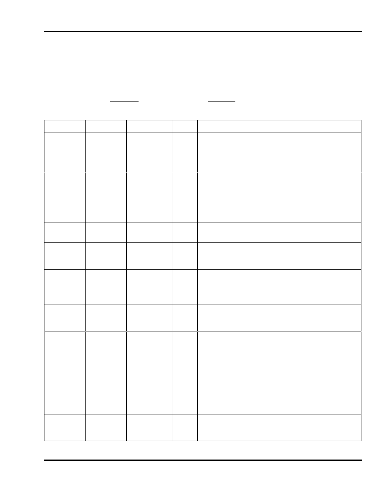
MODEL YB8 MAINTENANCE
Maintenance
Suggested Maintenance Schedule
The YB8 sampler requires only minimal maintenance to ensure proper and reliable operation. T he
following is a listed of suggested maintenance items and estimated times for accomplishing those tasks. Your
actual times and needs may differ.
Plan Item Frequency Time Description of Maintenance
Maintenance Lubrication Only as needed 10 The peristaltic pump requires no regular lubrication.
min
Inspection Pump Tubing Every Week 1 min See Below.
Maintenance
Inspection Pump Case Every Month 3 min Manning recommends occasional cleaning to remove
Maintenance particulates that if caught between the wall and the tube, can
cause increased wear of the pump tubing. Do not apply any oil
or other lubricating substances to the pump body as this will
inhibit the ability of the pump to operate correctly and will
significantly impact the life of the pump tubing.
Inspection Pump Rollers Every Month 2 min Manning recommends occasional cleaning to ensure smooth
Maintenance rolling and less wear of pump tubing.
Inspection Clear Pump Every Month 3 min Check to ensure that the clear lid is clean of residual materials
Maintenance Lid and contaminants so that the operation of the pump can be
clearly seen.
Inspection Strainer Every Week 10min Ensure that the strainer is not collecting materials that would
Maintenance inhibit fluid from reaching the pump. If material is collecting,
clean the strainer and reposition at the appropriate spot in the
flow stream.
Inspection Intake tubing Every Week 4 min Ensure that the connectors are fitting tightly together. This
Maintenance connectors ensures the sampler is not experiencing vacuum leaks which
can degrade the samplers performance.
Inspection Liquid Every Week 2 min Inspect the liquid sensor.
Maintenance Sensor Continuity Type - Make sure that good connection is being
made on the continuity sensor. Check to make sure that no
foreign matter is making a connection between the leads.
Cleaning of the inside of the sensor is recommended to ensure
good continuity is maintained for the detection of liquid.
Ultrasonic - Make sure that good contact is being made
between the tubing and the ultrasonic sensors.
The tubing
should be seated firmly in the sensor block with the
tubing in solid contact with the walls of the sensor.
Inspection Intake tubing Every Month 10 Check the intake tubing to ensure that it is clean. Cleaning
Maintenance min can be accomplished by running a cleaning solution through
April 1999/Manning Environmental Inc.
the tubing by using the test cycle feature of the unit.
Page C-1
Page 92

MAINTENANCE MODEL YB8
Inspection Discharge Every Month 3 min Examine the discharge tubing for build up of organic and
Maintenance Tubing particulate matter. If there is build up, follow the same
procedure for cleaning the intake tubing. Replace as necessary.
Inspection Electronics Every Month 2 min Clean as needed with warm water and very mild soap
Maintenance Enclosure
Inspection Keypad Every Month 2 min Clean as needed with warm water and very mild soap. Harsh
Maintenance abrasive cleaning products can damage the keypad and scratch
the clear window to the display
Inspection Sealing Every Year 5 min Unscrew the electronics enclosure from the refrigeration
Maintenance Gasket system and ensure that the gasket is free from debris and is
maintaining its shape and consistency. If the gasket is
exhibiting signs of wear, contact the Manning service
department for information on replacement. Under normal
operating conditions, the gasked should provide many years of
life
Inspection Sample As often as 15 The sample bottles should be checked frequently to ensure that
Maintenance Bottles needed min they are clean. EPA cleaning protocol should be used in the
cleaning of the bottles.
Maintenance Z-Rust Every Year 8 min Once a year, the Z-rust capsule which is used to absorb
Capsule moisture (in the form of humidity) should be replaced
Maintenance Lithium Every 3-5 years 12 The sampler contains an internal lithium battery which should
Battery min be replaced every 3 to 5 years
Peristaltic Pump
The peristaltic pump used in the Manning Environmental Inc. YB8 is designed for long life and trouble free
service. The following is a list of rout ine maintenance items:
Clean around inside of pump to remove particulate
matter which can decrease pump tube life
Page C-2
April 1999/Manning Environmental Inc.
Page 93
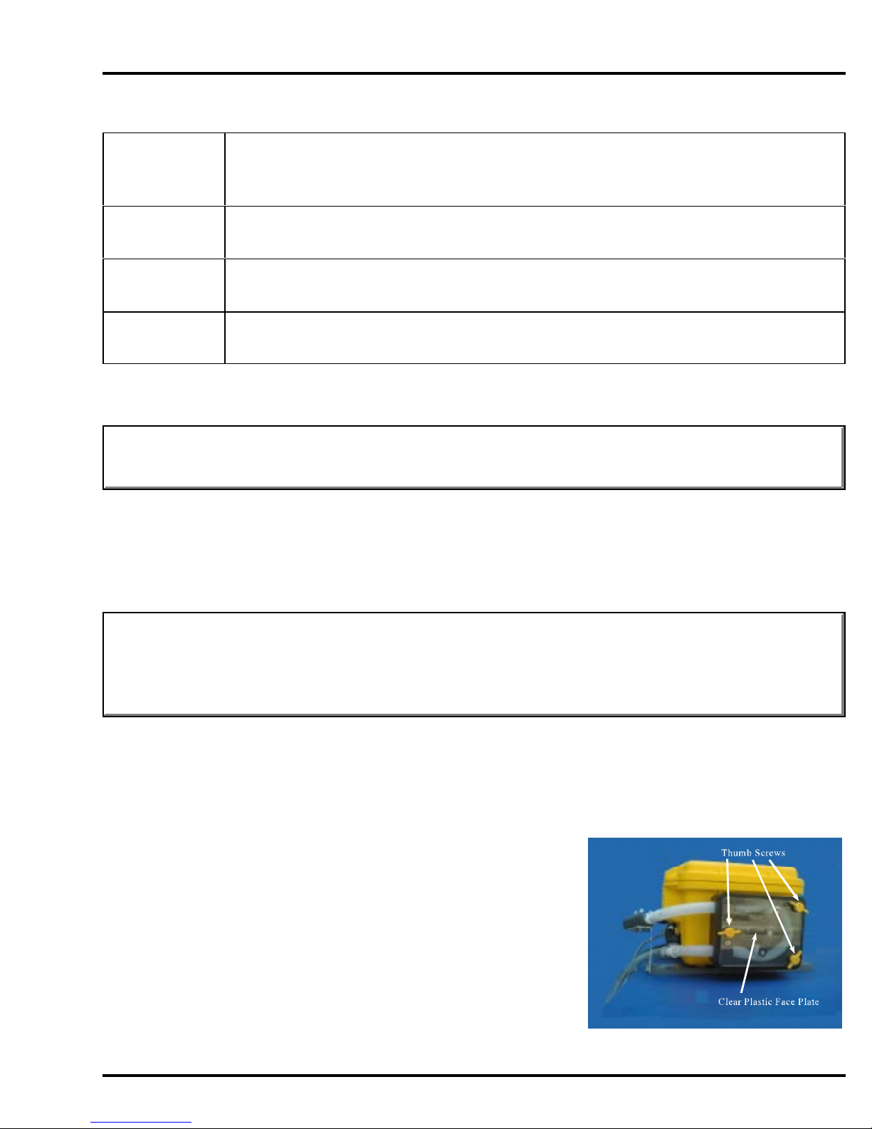
MODEL YB8 MAINTENANCE
Lubrication The peristaltic pump requires no regular lubrication. If chattering starts to occur in the
pump rollers, a very small amount of very lightweight oil may be applied. I f the
chattering does not stop, replacement may be necessary.
See Below.
Pump Tubing
Pump Case Manning recommends occasional cleaning to remove particulates that if caught between
the wall and the tube, can cause increased wear of the pump tubing.
Pump Rollers Manning recommends occasional cleaning to ensure smooth rolling and less wear of
pump tubing.
Replacement of Pump Tubing
WARNING: Always disconnect the power to the sampler before opening the pump to replace the
tubing. Failure to do so may lead to serious injury.
The peristaltic pump used on the Manning Environmental Inc. Model YB8 has been designed to facilitate
the changing of pump tubing. The unit is mounted in a vertical position. The unit also employs a clear
plastic face plate to allow the user not only to see how the tubing should lie within the pump but also to aid
in tubing alignment and to allow the user to visually verify that the pump is operating correctly. Perform the
following steps to change the pump tubing:
WARNING: The orientation of the intake and discharge hoses must not change when replacing the
tubing. I f the orientation changes, the unit will operate in reverse of its proper operating
procedure. T his means it will try to draw a sample out of the sample container instead of
out of the source liquid.
1) Verify there is no power being applied to the unit. The unit has an integral safety kill switch which
is intended to prevent powered rotation to the pump should the clear plastic face plate be
removed. However, power should always be turned off to the unit as an added measure of safety.
2) Remove the 3 thumb screws which hold down the clear
plastic face plate. Lift off the plate.
3) Remove the tubing from the liquid connectors which are
attached to the liquid sensor (continuity type). For
ultrasonic type liquid sensors, disconnect the tubing from
the liquid connectors and then slide the hinged lid of the
top of the liquid sensor and then pull the tubing out of the
liquid sensor. Then remove the tubing from around the
rollers. There are no designated ends on the tubing so the
April 1999/Manning Environmental Inc.
Page C-3
Page 94
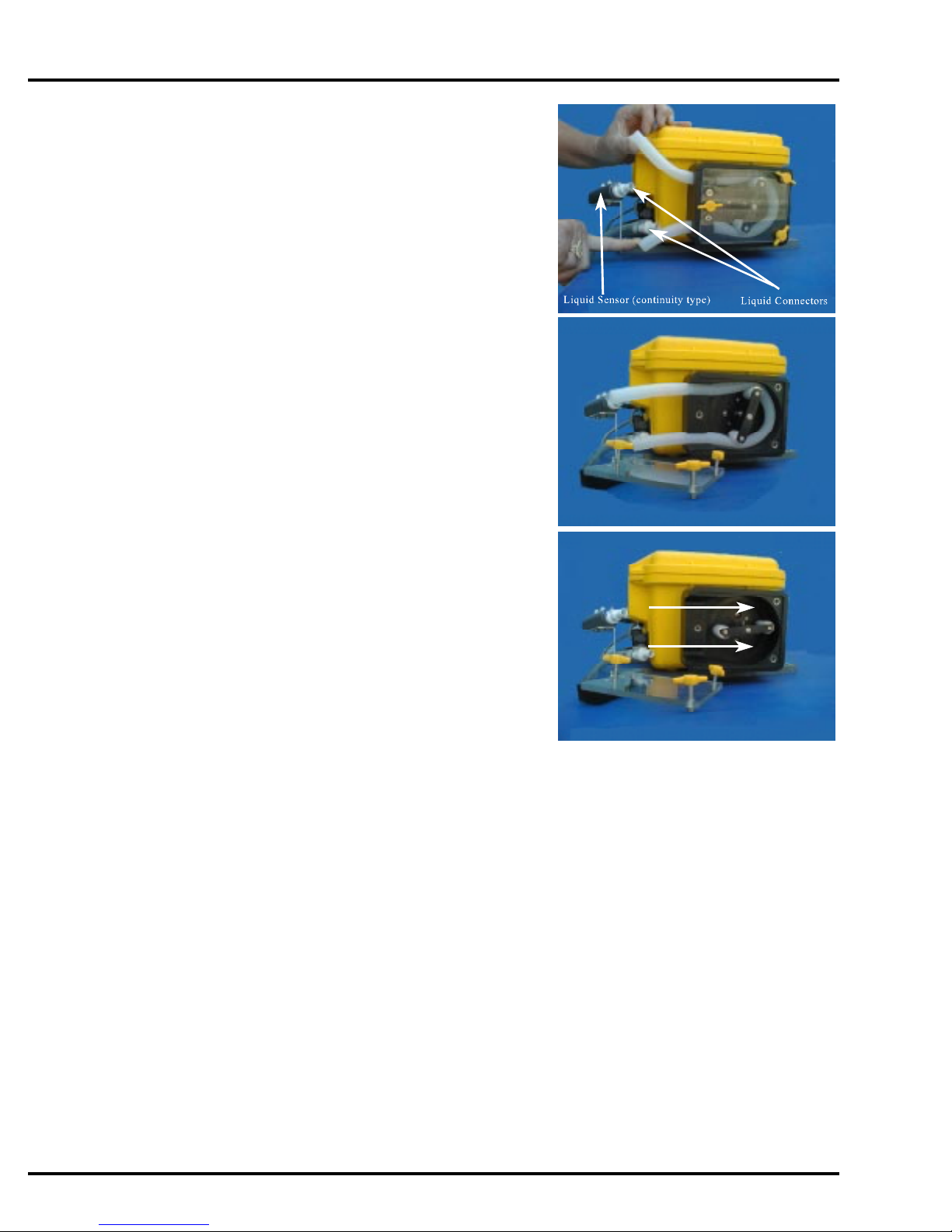
MAINTENANCE MODEL YB8
orientation (wh
ich end is placed on the inlet side and which end is
placed on the outlet side) does not matter.
4) Place the new tube in the pump making sure it is seated
flush against the inside wall of the pump. Pushing on the
tube to get it flush against the back wall of the pump will
help. It should follow the curve of the cavity with no gaps
between the tubing and the wall and have equal amounts of
tubing extending out past the pump housing.
5) Once the tube is back in place, reconnect the tube to the
liquid connectors or in the case of the ultrasonic sensor,
replace the tube in the sensor, making sure that is seated in
the bottom of the sensor and that good contact is made
with both walls of the sensor. Close the hinged lid and
secure. Re-install the clear plastic face plate and tighten it
securely with the 3 thumb screws removed earlier. Do not
overtighten the screws. The face plate is made from clear
material to aid in confirming that the pump tubing is
correctly installed. Now that the cover is back on, look
through it and make sure the tubing still follows the curve
of the pump cavity with no gaps. Also verify that equal
lengths of the tube extend out both the inlet and outlet
sides of the pump. Insert the connectors back into the
ends of the pump tubing making sure to maintain the
orientation of the intake and discharge lines. Run a test
cycle and check to see that when the pump is turning that
the tubing is staying in place within the pump and that it is
not “riding” up or down. If the tubing is “riding up or
down, you can affect this by twisting the tubing at the inlet
to the pump either clockwise or counterclockwise as the pump is turning. You should see the
tubing either go up or down when twisted. T wist it till the tubing is centered between the rollers
and stays there when the pump is going forward or backward.
Apply Pressure in this direction when reinstalling
the tubing to ensure that it fits closely to the curve
of the pump
6) Reset the tube life pump count in *19. A peristaltic units ability to operate and perform to
specifications, such as transport velocity and lift height is, to a certain extent, determined by the
medical grade silicone rubber pump tubing used in the system. T he characteristics of the tubing
change as it wears. It becomes less resilient, less able to maintain its shape, develops pinch points
on the outside edge of the tube, and as such is not capable of the performance it had when it was
new. T o maintain optimum performance, it is necessary to monitor the wear on the tube. * 19
does this by enabling the operator to set a maximum number of pump revolutions, the tube
currently in use, will be allowed to withstand. T his, in effect, determines the tube's useful life.
Manning recommends not exceeding 1,000,000 pump revolutions for a singular tube as, by this
time, there is risk that the tubing could fail causing a variety of problems. *19 should be used
every time the pump tubing is changed. T he user will be alerted to change the tubing, when the
tubing reaches the number of counts set. The warning will appear, every time the user executes a
Page C-4
April 1999/Manning Environmental Inc.
Page 95

MODEL YB8 MAINTENANCE
Program Mode, by pressing <START>. Since all programs are initiated by pressing <START>
the warning will always appear, if appropriate, before the program is initiated. T his allows the
user the opportunity to exit the program and change the tubing. Once the tubing is changed, the
user can re-enter the program and begin sampling.
When the pump tubing is to be changed, t he user will enter into *19 Mode, just like entering any of the other
* Modes. T he sampler will prompt the operator to clear the current pump count by pressing 1, or to
maintain the current count by pressing 0. It is advisable to reset the pump counts when changing the tubing
so an accurate accounting of the number of revolutions, the tube in the pump has experienced, can be
obtained. At this juncture the user will be asked to enter a number for the tube life warning which represents
the number of revolutions the current tube will be allowed to accumulate before a warning is issued. Once
entered, the system will return to the sampler ready prompt and the system will be ready to program.
Display on LCD Explanation
SAMPLER READY
04/30 04:30:02
ENTER * MODE?
__ __ 04:30:02
0=MAINTAIN 1=CLEAR
__ 04:30:02
This display shows the sampler is ready to program. I t displays the
current time. From here the user can enter any TIME, FLOW, or
* Mode. Press the * key to access the * Mode.
Prompts the user to enter either a program or a * Mode. Press 19
and <ENTER> to proceed.
This prompt is asking the user to determine how the system will
handle the current accumulation of revolutions:
0 - This maintains the current revolution count. T his is useful if
the operator wishes to increase the number of revolutions the
current tubing can accumulate before a tube life warning is
issued. For example, assume the current tubing has 200,000
revolutions. The operator really wants the warning to come
on at 400,000. The 0 key would be pressed instead of 1 to
maintain the history the tubing has already generated. The
user would then enter 0400 (for 400,000) at the TUBE LIFE
WARNING prompt (see below).
1 - This resets the current revolution count. This is necessary if
the user is going to be placing brand new tubing into the
system. With the counter reset the user knows exactly how
many counts it will take for the sampler to issue a warning to
change the tubing.
April 1999/Manning Environmental Inc.
Page C-5
Page 96

MAINTENANCE MODEL YB8
TUBE LIFE WARNING?
__ __ __ __ 04:
30:02
Enter the maximum number of revolutions the tubing will accept
before the sampler issues a pump tube warning. The number
entered is in terms of thousands (in other words it adds 3 0’s to the
end of the number entered) so if 0500 is entered, the sampler
would see it as 500,000. Entering 4000 equals 4,000,000 and
0060 would be 60,000, etc. When the number of revolutions meet
or exceed the pump counts set by the user, a pump life warning
will be issued. The default is 1,000,000.
Cleaning the Control Panel and Electronics Enclosure
Use a mild cleaning solution and wipe with a soft, lint-free cloth. T he clear window on the membrane keypad
is easily scratched, so be very careful when cleaning. The exterior of the electronics enclosure is constructed
of thick walled injection molded structural resin and is designed to withstand a wide variety of conditions.
The unit conforms to NEMA 4X,6 criteria, when the unit is latched shut. Please be sure to close and latch
the unit when not programming. T his will ensure that the keypad is not exposed to the elements and will
increase its useful life.
CAUTION: Do not use harsh cleaners (detergents, solvents, etc.) which can damage the panel surface.
Do not use abrasives which can scratch the panel and fog the window above the LCD
display.
Cleaning the Wetted Parts
Note: Solvents and solvent contaminated fluids must be disposed of according to approved procedures.
Manning Environmental Inc. recommends instituting a cleaning regime
for the sampling equipment. The following are a few of the many
reasons why a cleaning regime is important:
1. It validates that the samples t aken will be as free as
possible from constituents that are not contained
within the sample itself.
2. It contributes to ensuring that the statistical validity
of the samples being examined will be maximized
by reducing systematic error, if t he regime is followed very closely.
3. It contributes to the longevity of the sampling equipment.
4. It provides documentation for challenged results.
For a detailed description of a cleaning protocol refer to U.S. Environmental Protection Agency Publications
Page C-6
April 1999/Manning Environmental Inc.
Page 97

MODEL YB8 MAINTENANCE
EPA-600/4-77-039 ("Sampling of Water and Wastewater" by Dr. Phillip E. Shelley), or consult with the
facility that will do the actual testing of the samples. T hey could probably assist in setting a cleaning regime
that will help produce the most accurate results possible.
The following procedures are very general outlines of procedures for cleaning certain parts of the sampler:
Intake Hose
There are two types of intake hose used with the sampler - PVC and
Teflon . PVC intake hose is used for general purpose sampling
(Non-Toxic) applications. T eflon hose is used for priority pollutant
®
®
sampling (Toxic) applications.
1. Remove the intake hose. R emove the strainer if
necessary.
2. Wash the intake hose and strainer using a
cleaning solution appropriate for the application.
The use of methylene chloride or other solvents
may leave a residue that could contaminate the sample. Use a test tube brush to scrub the
internal surfaces of the strainer. Pull the brush through the hose with a wire to clean the
internal surfaces of the hose.
3. Rinse the hose and strainer thoroughly in clean water (warm water is best) and
reassemble.
It may be easier and more convenient to simply use a new hose for each sample configuration. This
eliminates cleaning and disposal of potentially hazardous regulated chemicals.
Liquid Sensor
The continuity type liquid sensor will need to be cleaned occasionally. Like any piece of the sample tract, it
has the abilit y to collect particulate matter, which needs to be
removed. By removing this particulate matter, it ensures that you will
receive optimum performance from the unit.
The ultrasonic liquid sensor will not need to be cleaned. By changing
the pump tubing you in effect, clean, the ultrasonic sensor.
1. Remove the pump tubing from the liquid
connectors.
2. Insert a bottle brush or other scrubbing type
device and vigorously insert the scrubber in and out of the sensor.
3. Reconnect the pump tubing to the liquid connectors and run a manual cycle with clean
April 1999/Manning Environmental Inc.
Page C-7
Page 98
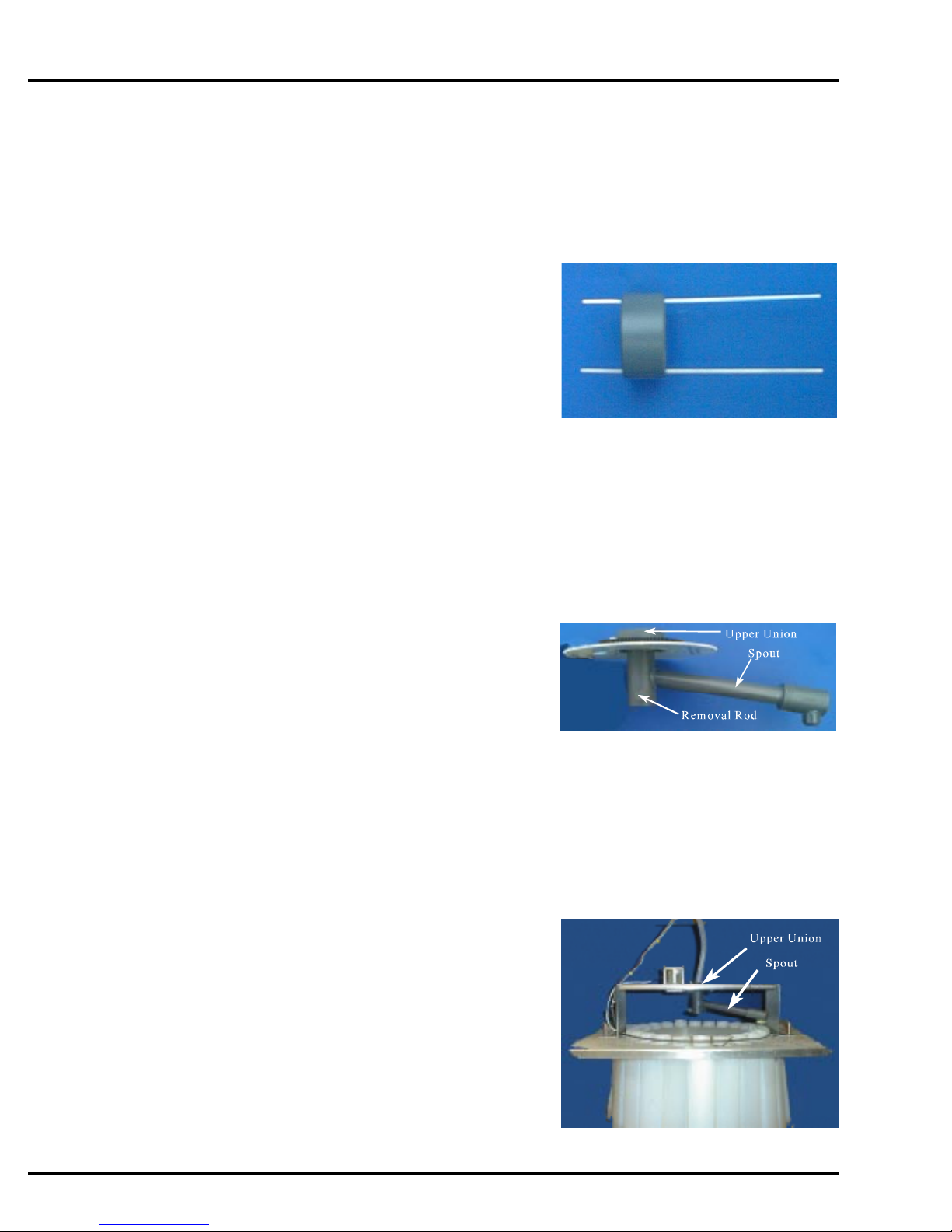
MAINTENANCE MODEL YB8
water to flush any material that was removed from the liquid sensor out of the sample
tract.
Bottle Full Sensor (Single Bottle Units Only)
1. Locate the bottle full sensor in the neck of the bottle. Either remove the leads from the
ends of the bottle full sensor probes or disconnect the black rubber mating connector.
Remove the bottle full sensor from the discharge
line by sliding it off.
2. The unit is made of high grade stainless steel which
is approved by the EPA for toxic or non-toxic
applications. Clean the probes, ensuring that their
is no buildup on the stainless steel probes.
3. Reconnect the unit, reversing the procedure used to remove it. If you disconnected the
leads from the stainless steel probes, make sure they are firmly attached.
Spout (Multiple Bottle Units Only)
1. Remove the spout from the upper union by gently pulling the spout gear from below.
2. Wash the spout with the appropriate cleaning
3. Rinse thoroughly with clean water (warm water is
Sample Containers
1. Wash with the appropriate cleaning solution. Use a test tube brush to clean the internal
2. Rinse thoroughly in clean water (warm water is
3. Autoclave glass bottles, if desired. Do not
(Rotating back and forth may help).
solution. Use a test tube brush to clean the internal
surfaces of the spout and upper union.
best) and re-assemble. When replacing the spout,
the timing mark on the st epper motor gear must align with t he timing mark on the spout
gear.
surfaces.
best).
autoclave plastic bottles or caps
since they are constructed of polyethylene.
Refrigerator
Page C-8
April 1999/Manning Environmental Inc.
Page 99

MODEL YB8 MAINTENANCE
The refrigerator that comes with the YB8 is an industrial grade unit. It has many features and options that
are not found on consumer models. These features make it more resistant to weather, allow it to maintain
EPA recommended temperatures, and ensure long life in the harshest environments. As durable as the
refrigerator is there are things that can be done to promote longer life. These items are covered here, but are
also covered in the manual that comes with the refrigerator. If you should encounter problems that cannot be
addressed with this manual or the manual included with the refrigerator, please contact Manning for
assistance.
Condenser
The condenser tubing under the cabinet for forced air units does not require frequent
cleaning; however, satisfactory cooling depends on adequate ventilation over the
condenser. Be sure that nothing obstructs the air flow openings in the lower front of the
cabinet. At least once or twice a year brush or vacuum lint and dirt from the condenser
for efficient performance by unscrewing the grill on the bottom front of the cabinet
Cabinet
The stainless steel or painted cabinet can be washed with mild soap and water and
throughly rinsed with clear water. Never use abrasive scouring powders.
Interior and Door Gasket
Wash interior compartment with mild soap and water. M ix 2 tablespoons of baking soda
with one quart of warm water. Do not use abrasive powders, solvent, polish cleaner or
undiluted detergent.
Energy Saving Tips
A. Reduce door openings as much as possible
B. Close the door as soon as possible after opening
C. Keep the coils on the bottom of the refrigerator clean
D. Adjust the temperature control to a warmer temperature when maintaining 4 C is
not necessary
E. Don’t put hot material into the refrigerator
F. Keep the refrigerator away from heat generating equipment
Troubleshooting
Problem Possible Cause/Solution
Odor in Cabinet Interior needs cleaning
Noisy Operation Cabinet not level
0
Cabinet Vibrates Cabinet not level
Appliance will not run Temperature control turned to OFF
April 1999/Manning Environmental Inc.
Line cord not plugged in
No power at electrical outlet
Blown fuse
Page C-9
Page 100

MAINTENANCE MODEL YB8
Appliance runs to l
Moisture collects inside To many door openings
Moisture collects on outside surface Hot humid weather increases condensation, as
Interior too hot/too cold Control set improperly
Temperature Control
Initially set the cold control knob midway between the numbers. T he dial sett ing is established at
the top of the knob After at least 2 hours, adjust to the temperature that suits you. The higher
the number you select the cooler the temperature. The temperature control knob is located at the
bottom front of the cabinet, just behind the square opening near the middle of the grill.
ong Prolonged door openings
Environmental Protection
Control set to cold
Condenser needs cleaning
Prolonged door openings
Hot humid weather increases condensation
humidity decreases, moisture will disapear
Control set improperly
Faulty thermostat
Once a year (or as necessary) replace the Zerust sponge inside the enclosure. If the sampler is in an area of
high humidity, additional desiccant may be necessary.
Removing and Replacing the Controller
To remove the controller, remove the hold down screws, disconnect the cables, hose, and tubes.
To replace the controller, reinstall the hold down screws and reconnect the cables, hose and tubes.
Page C-10
April 1999/Manning Environmental Inc.
 Loading...