

Page 1

19_J05xxx_ SPB 358 E&C.indd 1
9/1/19 5:10 PM
Before Use
Thank you for purchasing a
MANN+HUMMEL Duct Air Quality
Monitor. Before using the product,
please read this operating manual and
follow the instructions carefully to
prevent any accidents.
Warranty and Service
Scope of Warranty:
•
The product is used according to
the instructions in the operating
manual;
•
The product is handled properly
according to its intended usage;
The MANN+HUMMEL warranty does
not apply if the product is damaged
due to accidents, errors, normal wear
and tear, or inappropriate usage.
Please refer to the MANN+HUMMEL
website at www.mann-hummel.com
for more information or assistance.
EN
1
Page 2
19_J05xxx_ SPB 358 E&C.indd 2
9/1/19 5:10 PM
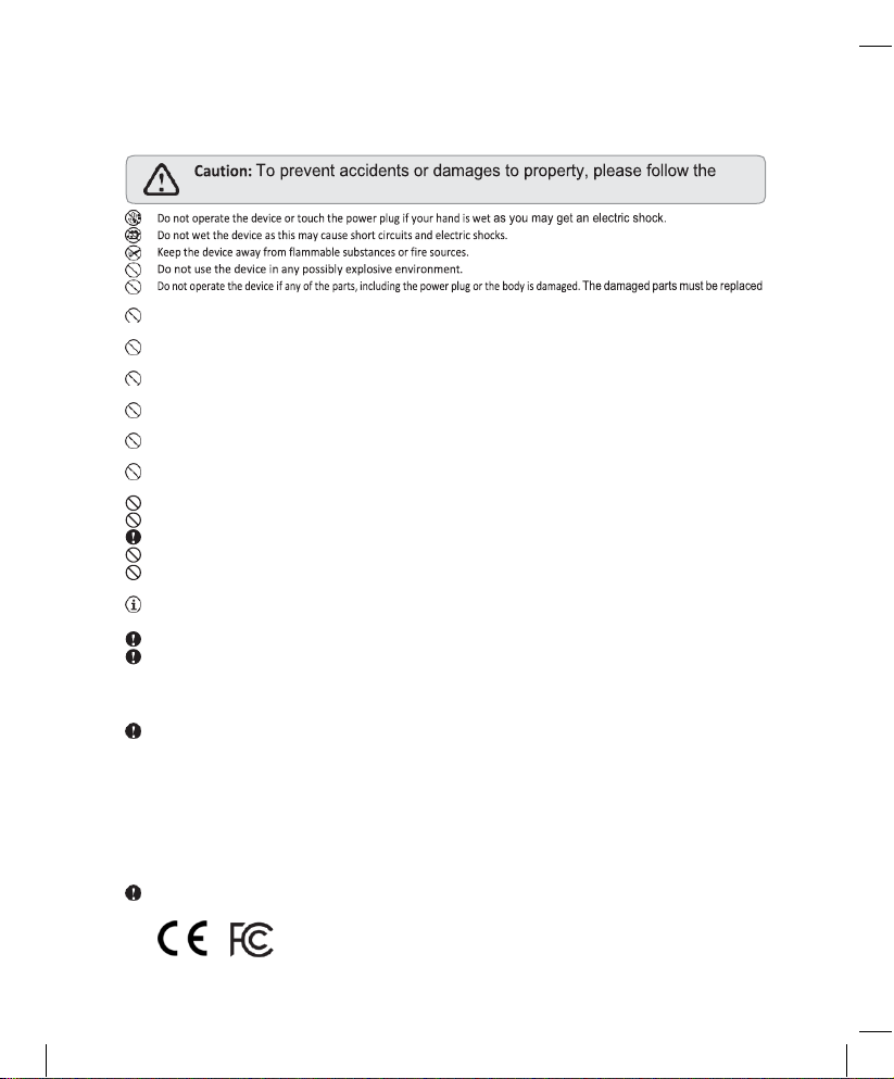
guidelines and instructions below.
Important Information
by the manufacturer or authorized service center in order to avoid hazards.
Do not disassemble, repair or alter the device without authorization.
Unauthorized disassembly or repair may cause failure and danger.
Unauthorized alteration may result in fire or breakdown.
Unless under supervision by persons responsible for their safety,
persons who are not familiar with the operating instructions, are not
allowed to o perate the device.
If the rated voltage of the product is different from the local standard voltage, do not c onnect the device to the power source.
Otherwise, it may cause damage to the product or fire.
The installation place of the device should be stable enough to bear its weight
with considering the influence of strong wind, typhoon
and earthquake to avoid its falling and the damage it may cause.
Parts and components intended for the installation should be used.
Do not use parts and components other than those provided in
the packagin g or r ecommended.
The filter should be used to reduce the occurrence of failures and prolong the service life of duct device, and the
filter should be
changed after hundreds of hours working.
Do not block the air inlets and outlets of the device as it may cause damage to t he device.
Do not connect t he device to p ower source u ntil all installation work are finished.
The max op erating temperature of the product is 40° C and shouldn’t be lo wer than 0°C.
Do not u se the SPB 358 in dust y envi ronments.
Otherwise the sensitivity, accuracy and lifetime of the device will be affected seriously.
The sensors and chips used in this device are high tech precision instruments; to minimize interference to the precision components,
please prevent the u nit from being exposed to high temperature, high humidity, combustible gases and liquids.
RF Power ( Output power): 16dBm (2412 MHz – 2462MHz)
Declaration of Conformity
This device complies with the essential requirements in Directive 2014/53/EU, and can be used acros s EU member states or regions.
This device complies with pa rt 15 of the FCC Rules (FCC ID: 2AQ3Q-SPB358). Operation is subject to the following two conditio ns:
(1) This device may not cause harmful interf erence, and
(2) This device m ust accept any interfere nce received, including interfe rence that may cause undesired operation.
Changes or modi fications not expressly approved by the part y responsi ble for compliance could void th e user’s authority to operate
the eq uipment.
This device has been tested and found to comply with the limits for a Class B digital device, pursuant to part 15 of the FCC Rules.
These limits are designed to provide reasonable protection against harmful interference in a res idential installation. This e quipment
generates, uses ,and can radiate radio frequency energy and, if not installed and used in accordance with the instructions, may cause
harmful in terference to radio communications.
However, t here is no g uarantee that interfer ence will not occur i n a particular installati on.
If this equipment does cause harmful interference to radio or television reception, which can be determined by turning the
equipment off and on, the user is encouraged to try to correct the interference by one or more of the following measures:
- Reorient o r relocate th e receiving ante nna.
- Increase the separ ation between the equipment and receiver.
- Connect th e equipme nt into an outlet on a circuit dif ferent from that to w hich the receiver is conn ected.
- Consult the dealer or an exp erienced radio/ TV technician for help.
This equipment complies with FCC radiation exposure limits set forth for an uncontrolled environment. This equipment should be
installed an d operated with mini mum distance 20cm between the radiat or & your body.
2
Page 3
19_J05xxx_ SPB 358 E&C.indd 3
9/1/19 5:10 PM
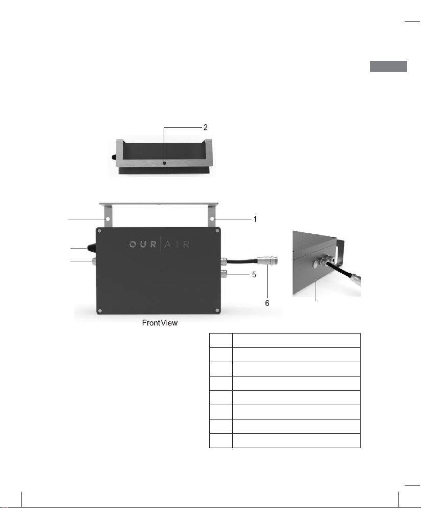
1. Overview
SPB 358 is a highly integrated air quality monitoring device which could detect
multiple parameters of PM2.5, CO2, TVOC, Temperature and Humidity. It could
be widely used in the duct air quality monitoring and performance evaluation of
ventilation air system and air purifier.
EN
Top View
1
3
4
7
Right View
No. Description
1
Installation Hole ( 6 mm)
2 Installation Hole ( 8 mm)
3 Wi-Fi Antenna
4 Air Inlet
5 Air Outlet
6 Power 7
Configuration
3
Page 4
19_J05xxx_ SPB 358 E&C.indd 4
9/1/19 5:10 PM
Caution: Do not use parts and components other than those provided in the
packaging or recommended.
2. Installation
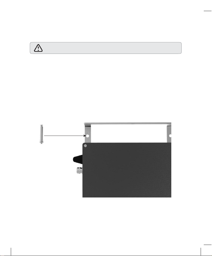
2.1 Option 1: Wall-mounting
Drill the holes and install the device on the wall through the 2 reserved holes
( 6mm) with expansion screws. Tighten the self-locking nuts to secure the
device. Please only use the expansion screws ( 6 mm) provided in the
packaging to do the installation. Alternatively, the nylon expansion screws could be
used depending on the wall conditions. The schematic is shown below:
4
Page 5
19_J05xxx_ SPB 358 E&C.indd 5
9/1/19 5:10 PM
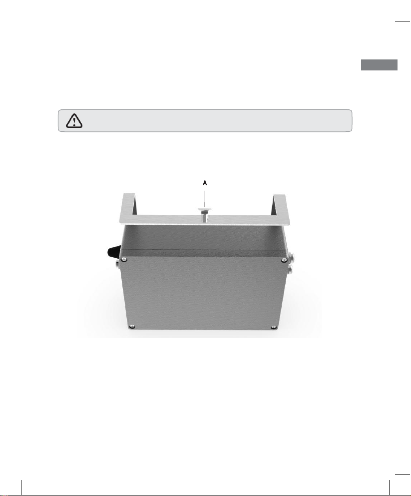
2.2 Option 2: Ceiling Installation
The users could use the hanging bolt on-site to install the device on the ceiling
through the reserved hole ( 8mm) on the top of the device.
EN
8mm
5
Caution: Secure the device through double nuts to prevent sliding.
Page 6
19_J05xxx_ SPB 358 E&C.indd 6
9/1/19 5:10 PM
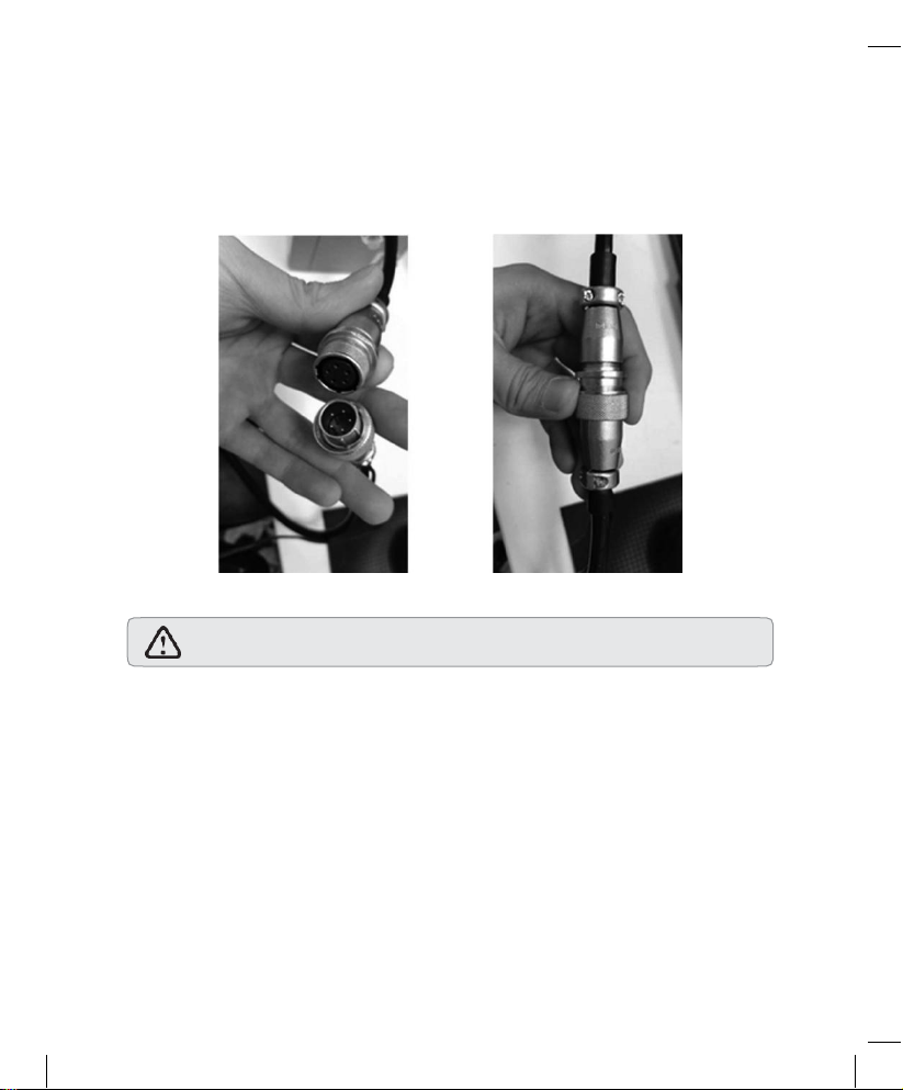
Caution: Do not force to connect the socket to avoid any damage.
3. Connectivity
Connect the power cord to the aviation socket and tighten the lock nut.
6
Page 7
19_J05xxx_ SPB 358 E&C.indd 7
9/1/19 5:10 PM
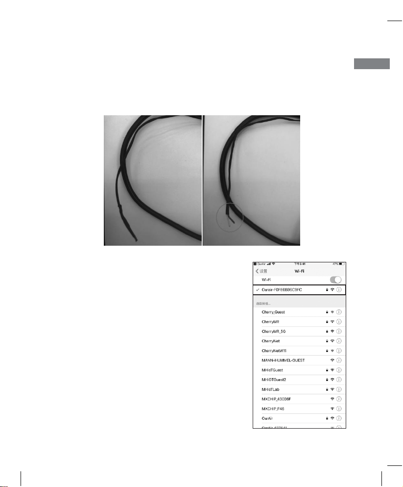
3.1 Modbus Connection (RS 485)
Users could transmit data through the reserved 485 communication wire. Before
connection, remove the protection layer of a heat-shrinkable tube and 2 wires of
yellow and blue color will be shown as below:
3.2 Wi-Fi Connection
1 .After power on, press the “Configuration”
button for around 8 seconds to initiate a Wi-Fi
hotspot starting with “Ourair_ xxxxxx”.
2.
For personal computer or laptop with
Windows OS, click on Wi-Fi setting and
connect to Wi-Fi of the “OurAir_xxxxxx”; For
iOS and Android mobile phone, go to setting
and connect to the Wi-Fi of the “OurAir_
xxxxxx”.
7
EN
Page 8
19_J05xxx_ SPB 358 E&C.indd 8
9/1/19 5:10 PM
Caution: It will take up to 3 seconds to restart the device. Please do not click
on any other commands during reboot to avoid errors.
3.
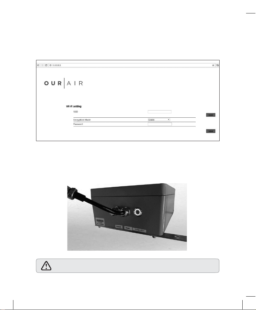
Open Internet browser like IE, Firefox, Safari or Chrome. Enter the IP address
10.10.10.1 in the address bar, then we will see the configuration interface for
Wi-Fi.
4.
Enter Wi-Fi Encryption information and click save to save your settings. The
device will restart to complete the Wi-Fi configuration. If the front LED is on,
the Wi-Fi is connected successfully.
8
Page 9
19_J05xxx_ SPB 358 E&C.indd 9
9/1/19 5:10 PM
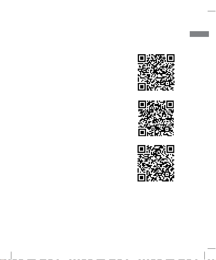
4. On-Boarding with the OurAir App
4.1 Download the OurAir App
1 For Android users, go to Google Play store
to search and download the mobile app
“OurAir” or scan the QR-code.
2 For iPhone users, go to App store to search
and download the mobile application “OurAir”
or scan the QR-Code.
3 For China Android users, go to Tencent
store to search and download the mobile
application “OurAir” or scan the QR-Code.
9
EN
Page 10
19_J05xxx_ SPB 358 E&C.indd 10
9/1/19 5:10 PM
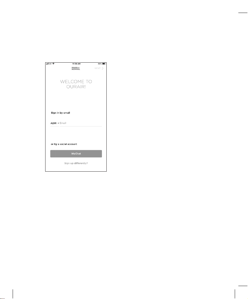
4.2 Adding the SPB 358 device to your account
1. Log-in to the OurAir App only by Email
10
Page 11
19_J05xxx_ SPB 358 E&C.indd 11
9/1/19 5:10 PM
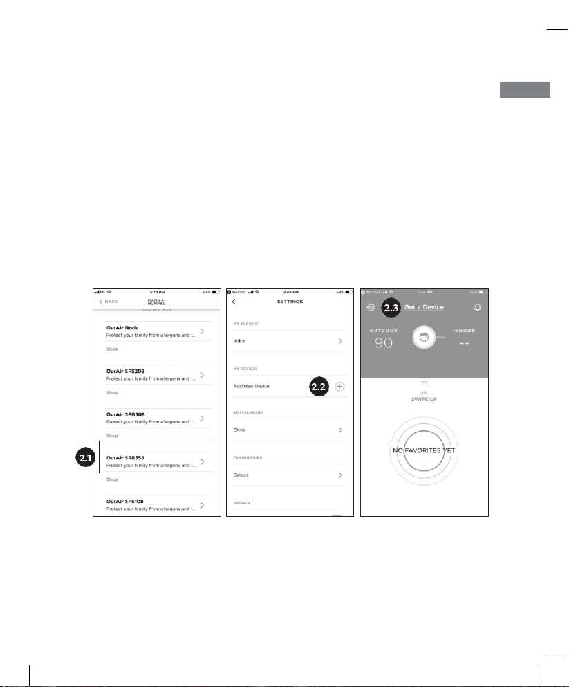
2. Adding device to your account
Ways to add your first OurAir device
2.1
– After you’ve logged in successfully for the first time, you can select the
device that you want to add
2.2
– Alternatively, you can go to the settings of OurAir App and tap the “+”
symbol to add new device
2.3
– You can also add the device at home screen (if no device was added
previously)
EN
11
Page 12
19_J05xxx_ SPB 358 E&C.indd 12
9/1/19 5:10 PM
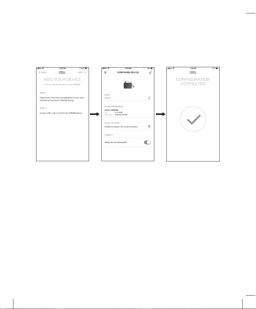
3. Pair a device with the OurAir App
Scan the QR code with OurAir App to pair the device.
12
Page 13
19_J05xxx_ SPB 358 E&C.indd 13
9/1/19 5:10 PM
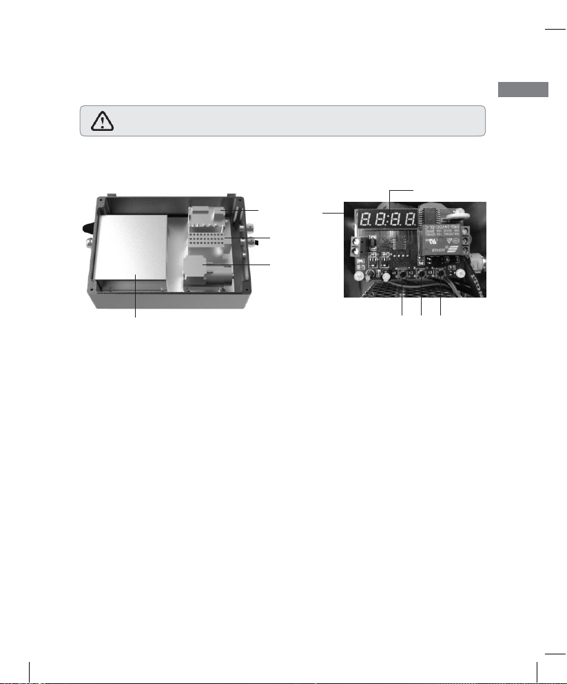
5. Clock Module Configuration
The interior structure of the device is as shown below:
EN
Clock Module
Transformer
Air Pump
Digital Screen
Test Cabin
K1 K2 K
3
5.1 The 4 modes of the clock module
P1: To set the daily working period of device.
E.g. The device automatically start working at 7:30 am and shut down at 5 pm
daily (Select the P1 mode, enter the numeric value of 0730 and 1700 in
turn).
P2: To set the pulse signal. It is not recommended for common users.
Consult the dealers or professionals if needed.
P3: To set the date and month on which the device will start to work
and shut down.
E.g. The device automatically start working on 1
st
Oct and shut down on 25
th
Dec (Select P3 mode, enter the numeric value of 1001 and 1225 in turn).
P4: To set the local date and time.
E.g. The SPB 358 device is used in Germany, and the local date & time is 15
th
Jun, 2:15pm (Select P4 mode, enter the numeric value of 0615 and 1415 in
turn).
13
Caution: consult the dealers or professionals to open the front cover of the
device to set the timer.
Page 14
19_J05xxx_ SPB 358 E&C.indd 14
9/1/19 5:10 PM
Caution: The default time zone of the clock module is set at UTC+8, and the
working time is from 7:00 am to 7:00 pm daily.
Caution:
When setting the numeric values, the first two digits of the nixie
start to flicker.
5.2 Functions of the buttons on the clock module
K1: To select the mode.
K2: To enter the mode or confirm the numeric value input.
K3: To adjust the numeric value.
Press K1 for around 2 seconds to activate the mode selection. Continue to press
K1 shortly to select the specific mode from P1 to P4. Enter K2 to confirm the
selected mode, and the digital screen will start to flicker waiting for the numeric
value input. Press K3 to enter the numeric value of you desired to key in, and
then press K2 to confirm the values input.
14
Page 15

19_J05xxx_ SPB 358 E&C.indd 15
9/1/19 5:10 PM
6. Product Specification and Packaging
Packaging list
Items Qty
Packaging box 1
SPB 358 unit 1
Power cable 1
Power adapter (if any)
1
Sampling tube (8mm OD x 5mm ID)
1
Sampling connector & washer
1
Expansion screw M6 (stainless steel)
2
Expansion screw (nylon)
2
Nut (for hanging bolt)
2
Operating manual 1
Warranty card 1
Quality card 1
15
EN
Page 16

19_J05xxx_ SPB 358 E&C.indd 16
9/1/19 5:10 PM
Product Specification
Certification
RESET™ (Grade B), RoHS,CE,FCC
Net Weight
3 Kg Dimensions
265mm x 185mm x 95mm
Input Voltage
100-240V
AC
Rated Voltage
24V DC
Rated Current
1 A
Connectivity
Wi-Fi (2.4GHz) / Modbus
Air quality parameters measured
PM2.5 (0-500 μg/m3)
CO2 (400 – 2000 ppm)
TVOC (125 – 600 ppb)
Temperature (0 – 40 °C)
Rel. Humidity (0 – 99 % RH)
Sampling frequency
1 min
Peak Air Flow
2.2 l/minute
Average Air Flow
2 l/minute
Air Pump Vacuum Degree
75 KPa
Air Pump Negative Pressure
≈ -24 KPa
Sensor calibration frequency*
12 Months
*Offered as part of OurAir service package.
7. Environment
Please play a part in preserving the environment by not discarding the
indoor air quality monitor with usual household waste at the end of its
lifespan. Please bring it in to a recycling collection point instead.
16
 Loading...