

Mannesmann Rexroth Indramat ECODRIVE DKC01.1, Indramat ECODRIVE DKC11.1 Project Planning Manual
Page 1
engineering
Buy: www.ValinOnline.com | Phone: 844-385-3099 | Email: CustomerService@valin.com
mannesmann
Rexroth
ECODRIVE
DKC01.1/DKC11.1 Drive Controllers
Project Planning Manual
DOK-ECODRV-DKC01/11.1*-PRJ3-EN-P
270950
Indramat
Page 2

About this documentation ECODRIVE DKC01.1/DKC11.1 Drive Controllers
Buy: www.ValinOnline.com | Phone: 844-385-3099 | Email: CustomerService@valin.com
Title
Type of document
Document code
Internal file reference
Editing sequence
ECODRIVE DKC01.1/DKC11.1 Drive Controllers
Project Planning
DOK-ECODRV-DKC01/11.1*-PRJ3-EN-P
•
209-0069-4390-03
Document identification of
Date Remark
previous editions
209-0069-4390-00 EN/05.96
209-0069-4390-01 EN/06.96
DOK-ECODRV-DKC01/11.1*-PRJ1-EN-P
DOK-ECODRV-DKC01/11.1*-PRJ1-EN-P
DOK-ECODRV-DKC01/11.1*-PRJ3-EN-P
May 96
June 96
July 96
May 97
Feb. 98
First edition
Revision
2nd edition
2nd Revision
new edition
Copyright
INDRAMAT GmbH, 1996
The reproduction and transm ission of this document, the use and c ommunication of its content to thir d parties without the expr essed c onsent of
INDRAMAT GmbH are forbidden. Violators are liable for the payment of
damages. All rights are reserved in the event a patent is gr anted or a utility model is registered (DIN 34-1).
Publisher
INDRAMAT GmbH • Bgm.-Dr.-Nebel-Str. 2 • D-97816 Lohr a. Main
Telephone +49 (09352) 40-0 • Telex 689421 • Fax +49 (09352) 40-4885
Dept. ENA (VS, HE)
Validity
The contents of this documentation and the availability of the product are
subject to change.
DOK-ECODRV-DKC01/11.1*-PRJ3-EN-P
Page 3

ECODRIVE DKC01.1/DKC11.1 Drive Controllers About this documentation
Buy: www.ValinOnline.com | Phone: 844-385-3099 | Email: CustomerService@valin.com
What is this
documentation for?
Supplementary documentation
It supplies information on:
•
planning the mechanical control cabinet
•
planning the electrical system in the control cabinet
•
logistic handling of the equipment
•
preparing the resources for start-up
"ECODRIVE DKC Servo Drives with MKD"
- Selection Lists DOK-ECODRV-DKC+MKD****-AUS1-EN-P
for selecting the motor controller combination.
"MKD Digital AC Motors"
- Project Planning Manual DOK-MOTOR*-MKD********-PRJ2-EN-P
for a detailed description of the ser vomotors and for the selec tion of the
required cable.
"ECODRIVE DKC01.1/DKC11.1 Drive Controllers"
- Description of Functions DOK-ECODRV-DKC01/11.1-FKB1-EN-P
for testing and selecting the functions.
"EMC in Drive and Control Systems"
- Project Planning 209-0049-4305-02 EN/04.96
for the EMC-compliant planning and installation of the drive system ( EMC
= Electromagnetic Compatibility).
DOK-ECODRV-DKC01/11.1*-PRJ3-EN-P
Page 4

About this documentation ECODRIVE DKC01.1/DKC11.1 Drive Controllers
Buy: www.ValinOnline.com | Phone: 844-385-3099 | Email: CustomerService@valin.com
Notes
DOK-ECODRV-DKC01/11.1*-PRJ3-EN-P
Page 5

ECODRIVE DKC01.1/DKC11.1 Drive Controllers Table of contents I
Buy: www.ValinOnline.com | Phone: 844-385-3099 | Email: CustomerService@valin.com
Table of contents
1 Introduction to the system 1-1
1.1 Application features..............................................................................................................................1-1
1.2 Overview of the functions.....................................................................................................................1-1
2 Safety instructions for electrical drives 2-1
2.1 General ................................................................................................................................................ 2-1
2.2 Protection against contact with electrical parts....................................................................................2-2
2.3 Protection agains t shock s caused by safety extra-low voltage (SELV)......................................... 2-3
2.4 Protection against dangerous movements........................................................................................... 2-4
2.5 Protection against magnetic and electromagnetic fields during operation and assembly ................... 2-6
2.6 Protection during handling and assembly............................................................................................2-7
2.7 Safe battery usage............................................................................................................................... 2-7
3 Selecting the components 3-1
3.1 Overview of the required components.................................................................................................3-1
3.2 Selection procedure.............................................................................................................................3-2
3.3 Compiling the required data................................................................................................................. 3-3
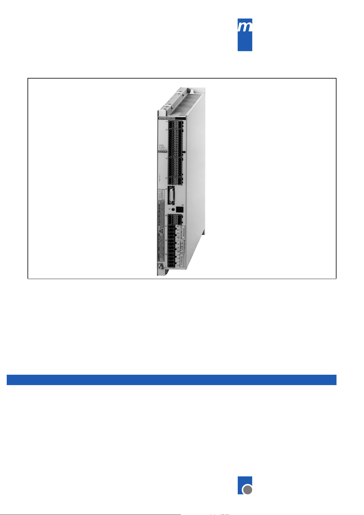
4 ECODRIVE DKC drive controllers 4-1
4.1 Hardware..............................................................................................................................................4-1
View of unit....................................................................................................................................4-1
Dimensional sheets and installation dimensions...........................................................................4-2
Technical data............................................................................................................................... 4-4
Type code and rating plate............................................................................................................ 4-7
4.2 Firmware..............................................................................................................................................4-8
4.3 An overview of the electrical connections............................................................................................4-9
Front view with supply terminals................................................................................................... 4-9
Overall connection diagrams....................................................................................................... 4-10
4.4 Electrical connection to the supply terminal strips.............................................................................4-14
Serial interface X1....................................................................................................................... 4-14
X2 positioning or stepper interface.............................................................................................. 4-18
X3 analog inputs and outputs...................................................................................................... 4-25
X4 terminals for the control circuit............................................................................................... 4-29
X5, X6, X7 motor connections ....................................................................................................4-30
X9 DC bus connection ................................................................................................................4-30
DOK-ECODRV-DKC01/11.1*-PRJ3-EN-P
Page 6

II Table of contents ECODRIVE DKC01.1/DKC11.1 Drive Controllers
Buy: www.ValinOnline.com | Phone: 844-385-3099 | Email: CustomerService@valin.com
5 BZM auxiliary bleeder module 5-1
5.1 Dimensioning the components relevant for regeneration ....................................................................5-1
5.2 Dimensional data and installation dimensions.....................................................................................5-5
5.3 Technical data......................................................................................................................................5-6
5.4 Front view.............................................................................................................................................5-6
5.5 Electrical connections.......................................................................................................................... 5-7
5.6 Type code and rating plate...................................................................................................................5-7
6 CZM Auxiliary Capacitance Module 6-1
6.1 Dimensioning ....................................................................................................................................... 6-1
6.2 Dimensional data and installation dimensions.....................................................................................6-3
6.3 Front view.............................................................................................................................................6-4
6.4 Electrical connection............................................................................................................................6-4
6.5 Type code and rating plate...................................................................................................................6-5
7 DC24V NTM power supplies 7-1
7.1 Application recommendations.............................................................................................................. 7-1
7.2 Technical data......................................................................................................................................7-1
7.3 Dimensional data and installation dimensions.....................................................................................7-2
7.4 Front views...........................................................................................................................................7-2
7.5 Electrical connection............................................................................................................................7-3
7.6 Type code ............................................................................................................................................ 7-4
8 NFD / NFE line filter 8-1
8.1 Selection .............................................................................................................................................. 8-1
8.2 Dimensional data and installation dimensions.....................................................................................8-2
8.3 Electrical connection............................................................................................................................8-3
8.4 Line filters for DC24V NTM power supplies.........................................................................................8-5
8.5 Type code ............................................................................................................................................ 8-5
9 DST / DLT transformers 9-1
9.1 Selection .............................................................................................................................................. 9-1
9.2 Autotransformers for DKC**.*-040-7-FW............................................................................................. 9-1
9.3 Autotransformers for DKC**.*-030-3-FW............................................................................................. 9-4
9.4 Electrical connection of the DKC via transformer ................................................................................9-6
9.5 Type code ............................................................................................................................................ 9-7
10 Planning the control cabinet 10-1
10.1 Notes on installing the control cabinet.............................................................................................10-1
Power dissipation........................................................................................................................10-1
10.2 Using heat-exchange units in the control cabinets ..........................................................................10-2
DOK-ECODRV-DKC01/11.1*-PRJ3-EN-P
Page 7

ECODRIVE DKC01.1/DKC11.1 Drive Controllers Table of contents III
Buy: www.ValinOnline.com | Phone: 844-385-3099 | Email: CustomerService@valin.com
11 Power connection 11-1
11.1 Direct power connection...................................................................................................................11-1
11.2 Line contactor/fuse protector ...........................................................................................................11-2
Calculating the phase current at the power connection..............................................................11-2
Selecting fuse protector Q1 and line contactor K1...................................................................... 11-3
11.3 Control circuit to the power connection............................................................................................ 11-4
11.4 Protection against indirect contact...................................................................................................11-5
12 Preparing for Startup 12-1
Required equipment.................................................................................................................... 12-1
13 Condition of the drive components on delivery 13-1
Packaging ...................................................................................................................................13-1
Accompanying documents..........................................................................................................13-1
Identification of the components .................................................................................................13-1
14 Index 14-1
DOK-ECODRV-DKC01/11.1*-PRJ3-EN-P
Page 8

IV Table of contents ECODRIVE DKC01.1/DKC11.1 Drive Controllers
Buy: www.ValinOnline.com | Phone: 844-385-3099 | Email: CustomerService@valin.com
Notes
DOK-ECODRV-DKC01/11.1*-PRJ3-EN-P
Page 9

ECODRIVE DKC01.1/DKC11.1 Drive Controllers Introduction to the system 1-1
Buy: www.ValinOnline.com | Phone: 844-385-3099 | Email: CustomerService@valin.com
1 Introduction to the system
1.1 Application features
The drive system with the ECODRIVE drive controllers is the most c osteffective solution off ering the highest functionality for almost any field of
application in which translatory or rotary motions are to be automated.
Outstanding performanc e data, an ex tensive r ange of f unc tions as well as
an excellent price-to-performance ratio represent the salient features of
this drive system.
Product features in terms of the technical applications are:
•
universal implementation
•
lower total costs
•
digital drive concept
•
highly dynamic operation
•
cost-effective direct connection to the power connection
•
software travel limit switch
•
absolute or incremental position detection
•
absolute or incremental position output
•
integrated holding brake control
•
increased operating safety
•
adjustable error response
•
automatic parameter matching
•
easy startup operation
1.2 Overview of the functions
The functions of the digital, intelligent drive system are dif ferentiated primarily according to the interface of the higher -level control. The fields of
application for the ECODRIVE drive controllers vary accordingly.
The drive controller DKC01.1 is used as a:
•
servodrive with integrated position control
•
servodrive with analog speed interface and integrated actual position
detection
•
servodrive with stepper interface.
•
servodrive with electronic gearbox function
The drive controller DKC11.1 repr esents a partic ularly cost-eff ective solution. It is used as a:
• servodrive with analog speed interface and integrated actual position
detection
DOK-ECODRV-DKC01/11.1*-PRJ3-EN-P
Page 10
1-2 Introduction to the system ECODRIVE DKC01.1/DKC11.1 Drive Controllers
Buy: www.ValinOnline.com | Phone: 844-385-3099 | Email: CustomerService@valin.com
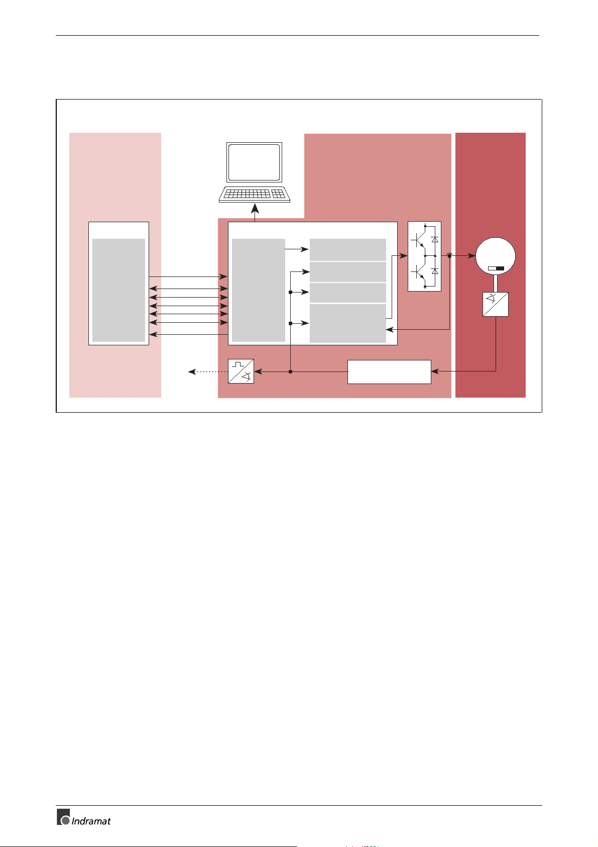
Servodrive with integrated position control
SPS-Control
I/O _ card
Selection
of the
positioning
records
Control inputs
Status outputs
Actual
position
value
MS-DOS - PC
Parameters
Diagnosis
Operating data
RS 232
RS 485
Stored
positioning
records
2° position 1
1
position 2
2
2
.
2
.
4
position 32
2
®
Drive processor
DKC01.1Drive controller
with POSITIONING-interface
Fine interpolation
Position control
Speed control
Field-orinted
stator current
control
High-resolution
positioning interface
AC-servo motor
MKD
M
~
3
~
~
FS0200.fh5
Fig. 1-1: Servodrive with integrated position control
•
Up to 32 positioning blocks can be stored in the drive controller and
selected over parallel inputs. The positioning block is executed
autonomously.
•
Mechanical translatory elements such as gear ratios or f eed constants
are adapted in the drive.
•
All position, speed, and acceleration data can be weighted independently of the axis kinematics.
•
A drive-internal referencing pr ocedure is available for cr eating a reference dimension.
•
The axis can be moved with the jog function during setup operation.
•
The positioning speed can be influenced via the feedrate override.
•
Travel limit switch inputs and axis limit values which can be parameterized are available for limiting the travel range.
• The drive status can be detected via status outputs.
DOK-ECODRV-DKC01/11.1*-PRJ3-EN-P
Page 11
ECODRIVE DKC01.1/DKC11.1 Drive Controllers Introduction to the system 1-3
Buy: www.ValinOnline.com | Phone: 844-385-3099 | Email: CustomerService@valin.com
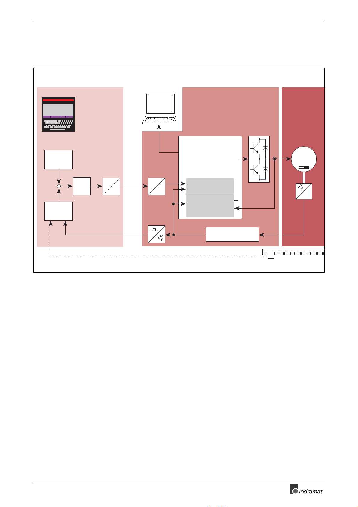
Servodrive with analog speed interface and integrated actual
position detection
Control unit
with position control
Parameters
Diagnosis
Operating data
Position
command
value
+W
-X
Positioning
interface
AC servo motor
MKD
MS-DOS - PC
Parameters
Diagnosis
Operating data
RS 232
DKC01.1 or DKC11.1 drive
controller with ANALOG interface
®
RS 485
Drive processor
M
3
Speed
command
value
K
v
DA
analog
A
D
± 10V
Speed control
Field-oriented
stator current
control
Actual
position
High-resolution
positioning interface
value
~
~
~
Linear scale
FS0201.fh5
Fig. 1-2: Servodrive with analog speed interface and integrated actual position
detection
•
The analog speed command value can be set to any value.
•
The actual position value is output either incrementally or absolutely.
•
Using a switching input, the drive can be shut down independent of the
command value and stopped free of drift during active control.
DOK-ECODRV-DKC01/11.1*-PRJ3-EN-P
Page 12
1-4 Introduction to the system ECODRIVE DKC01.1/DKC11.1 Drive Controllers
Buy: www.ValinOnline.com | Phone: 844-385-3099 | Email: CustomerService@valin.com
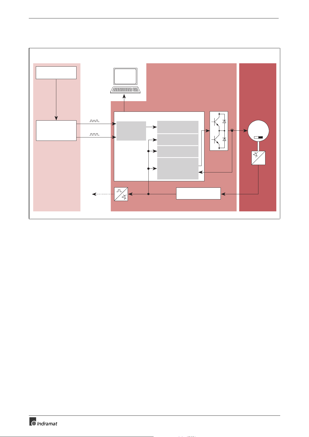
Servodrive with stepper interface
Control unit
with step pulse generation
Interpolation
Step pulse
generation
forwards
backwards
Actual
position
value
MS-DOS - PC
Parameters
Diagnosis
Operating data
RS 232
®
RS 485
Stepper
interface
DKC01.1 drive controller
with STEPPER interface
Drive processor
Fine interpolation
Position control
Speed control
Field-oriented
stator current
control
High-resolution
position interface
AC servo motor
MKD
M
3
~
~
~
FS0202.fh5
Fig. 1-3: Servodrive with stepper interface
•
The number of steps per rotor rotation can be set to any value between 16 and 65536.
•
The maximum step frequency is independent of the load. It is technically impossible to "skip" steps due to the position controlled operation.
•
The stepper interface can be set to three standard signal definitions for
exchanging signals between the control and the drive controller.
- quadrature signals
- forwards/backwards signals
- step and direction signal
•
A drive-internal referencing pr ocedure is available for cr eating a reference dimension.
•
The axis can be moved with the jog function during setup operation.
•
The referencing and jog speed can be influenced via the feedrate
override.
• Travel limit switch inputs and axis limit values which can be parameterized are available for limiting the travel range.
DOK-ECODRV-DKC01/11.1*-PRJ3-EN-P
Page 13

ECODRIVE DKC01.1/DKC11.1 Drive Controllers Introduction to the system 1-5
Buy: www.ValinOnline.com | Phone: 844-385-3099 | Email: CustomerService@valin.com
Servodrive with electronic gearbox function
Lead axis
transmitter
Lead axis
position
MS-DOS - PC
Parameters
Diagnosis
Operating data
RS 232
Step motor
interface
®
RS 485
Servodrive DKC01.1
with electronic gearbox function
Drive processor
electronic gearbox
Position control
Speed control
Field-oriented
stator current
control
High-resolution
position interface
AC-Servomotor
MKD
M
3~
~
~
FS0203.fh5
Fig. 1-4: Servodrive with electronic gearbox function
•
Operating modes
Speed synchronization
Angle synchronization
•
The lead axis position is given in degrees (360 degrees repres ent one
lead axis encoder revolution)
•
The lead axis encoder must be connected to the DKC stepper interface.
The maximum allowable signal frequency f
limits the number of lines Z
which can be emulated.
l
on the stepper interface
max
DOK-ECODRV-DKC01/11.1*-PRJ3-EN-P
Page 14

1-6 Introduction to the system ECODRIVE DKC01.1/DKC11.1 Drive Controllers
Buy: www.ValinOnline.com | Phone: 844-385-3099 | Email: CustomerService@valin.com
Notes
DOK-ECODRV-DKC01/11.1*-PRJ3-EN-P
Page 15

ECODRIVE DKC01.1/DKC11.1 Drive Controllers Safety instructions for electrical drives 2-1
Buy: www.ValinOnline.com | Phone: 844-385-3099 | Email: CustomerService@valin.com
2 Safety instructions for electrical drives
Please read the following instructions carefully before initial startup.
These safety instructions must be observed at all times.
If the product is transferred to a third-party, the safety instructions must be
included.
Improper use of this equipment and non-compliance
with the safety instructions provided can result in
damage, personal injury or, in extreme cases, death.
WARNING
2.1 General
INDRAMAT GmbH is not liable for any damages resulting from failure
to observe the safety instructions in this document.
•
Documentation in the relevant national language should be obtained
before initial startup if the language in this doc umentation is not perfectly understood.
•
Proper transport, correct s torage, ass em bly, and installation as well as
care in operation and maintenance are prer equisites for optimum and
safe operation of this equipment.
•
Qualified personnel:
Only qualified personnel should be permitted to operate this equipment
or work in its imm ediate vicinity. Personnel is considered qualified if it
has sufficient knowledge of the ass embly, installation, and operation of
the product as well as all warnings and precautionar y meas ures in this
documentation.
Furthermore, personnel should be trained, instructed or author ized to
switch electrical circuits on and off and to ground and m ark them in
accordance with the requirements of safety engineering. Personnel
should possess adequate safety equipment and be trained in first aid.
•
Use only replacement parts approved by the manufacturer.
•
All safety regulations and requirements for the specific application
must be followed.
•
The equipment is designed to be ins talled in mac hines for com merc ial
use.
•
Startup is only permitted once it is sure that the machine in which the
products are installed com plies with the requirements of the national
safety regulations and safety specifications of the application.
European countries: EC Directive 89/392/EEC (Machine Guideline)
• Operation is only permitted if the national EMC regulations f or the s pecific application have been met. European countries: EC Directive
89/336/EEC (EMC Guideline)
The instructions for installation in accordanc e with EMC requirements
can be found in the document "EMC Drive and Control Systems."
The responsibility for adherence to the lim iting values required by national regulations lies with the manufacturer of the equipm ent or machine.
DOK-ECODRV-DKC01/11.1*-PRJ3-EN-P
Page 16

2-2 Safety instructions for electrical drives ECODRIVE DKC01.1/DKC11.1 Drive Controllers
Buy: www.ValinOnline.com | Phone: 844-385-3099 | Email: CustomerService@valin.com
•
Technical specif ications as well as the connection and installation re quirements can be found in the produc t documentation and must be
observed under all circumstances.
2.2 Protection against contact with electrical parts
Note: Only relevant for devices and drive components with voltages ex-
ceeding 50 volts.
Coming into contact with components carrying voltages greater than 50
volts can be dangerous. Certain parts are under dangerous voltage when
operating electrical devices.
High Voltage!
Danger to life or risk of bodily injury!
⇒
Follow general construction and safety regulations
DANGER
when working on electrical installations.
⇒
Before switching on power, be sure that the ground
wire is permanently connected to all electrical units
according to the connection diagram.
⇒
At no time may electrical equipment be operated if the
ground wire is not permanently connected to the
proper terminals, even for brief measurements or
tests.
⇒
Disconnect the equipment from the power supply line
or the voltage source before beginning work. Secure
equipment from reclosure.
⇒
Wait 5 m inutes after switching off power to allow capacitors to discharge before using the equipment.
Measure the voltage of the capacitors before beginning work in order to eliminate dangers arising from
touching components.
⇒
Never touch the electrical connection points of a com ponent while the power is turned on.
⇒
Cover live parts properly before switching the equipment on so they cannot be touched. Covers provided
with the equipment must be installed bef ore operating
the equipment to prevent contact with live parts . The
equipment may only be operated with the covers designed for shock-hazard protection.
⇒
A GFCI protective device (ground fault circuit interrupter) cannot be used for AC drives! Protection
against indirect contact must be ensured by other
means, for exam ple, by using an overcurrent protection device in accordance with relevant standards.
European countries: in accordance with EN
50178/1994, section 5.3.2.3
⇒ For installation equipment protection against indirect
contact must be ensured using an external housing,
such as a control cabinet. European countries : in accordance with EN 50178/1994, section 5.3.2.3
DOK-ECODRV-DKC01/11.1*-PRJ3-EN-P
Page 17

ECODRIVE DKC01.1/DKC11.1 Drive Controllers Safety instructions for electrical drives 2-3
Buy: www.ValinOnline.com | Phone: 844-385-3099 | Email: CustomerService@valin.com
High discharge current!
Danger to life or risk of bodily injury!
⇒
All units and the motors m ust first be connected to a
WARNING
grounding point with the ground wire or must be
grounded themselves before switching on power.
⇒
The discharge current is greater than 3.5 mA. A permanent connection to the power supply line is therefore required for all units. European countries (EN
50178/1994, section 5.3.2.3)
⇒
Before startup operation always connect the protective conductor or the ground conductor. Otherwise the
housing may harbor high voltages.
2.3 Protection against shocks caused by safety extra-low voltage (SELV)
All connectors and terminals on INDRAMAT products with voltages from
5 to 50 volts are safety extra-low voltages offering a shock proof design to
meet the following standards:
•
international: IEC 364-4-411.1.5
•
European countries in the EC: EN 50178/1994, section 5.2.8.1
WARNING
High electrical voltages due to incorrect connections!
Danger to life or risk of bodily injury!
⇒
Only equipment and lines carrying protective extra low
voltage (PELV) may be connected to connectors and
terminals with voltages ranging from 0 to 50 volts.
⇒
Connect only voltages and circuits safely isolated from
dangerous voltages. Isolation can be achieved, for
example, by using safe isolation transformers, optocouplers or power supply independent battery operation.
DOK-ECODRV-DKC01/11.1*-PRJ3-EN-P
Page 18

2-4 Safety instructions for electrical drives ECODRIVE DKC01.1/DKC11.1 Drive Controllers
Buy: www.ValinOnline.com | Phone: 844-385-3099 | Email: CustomerService@valin.com
2.4 Protection against dangerous movements
Dangerous movements can be caused if the connected motors are not
controlled correctly.
There are various causes of dangerous movements:
•
faulty wiring or cable connections
•
operating the components improperly
•
defective measured value transmitters and primary detectors
•
defective components
•
errors in the software
These errors can occur just after the equipm ent has been switched on or
after an indefinite period of time.
The monitors in the dr ive components virtually exclude failur e in the connected drives. However, personnel safety requires that additional measures be taken to ensure corr ect operation. Faulty drive motions which are
influenced by the type of control and the operating status cannot be entirely excluded until the installed monitors take effect.
DOK-ECODRV-DKC01/11.1*-PRJ3-EN-P
Page 19

ECODRIVE DKC01.1/DKC11.1 Drive Controllers Safety instructions for electrical drives 2-5
Buy: www.ValinOnline.com | Phone: 844-385-3099 | Email: CustomerService@valin.com
Dangerous movements!
Danger may result in equipment damage, personal injury
or death!
⇒
DANGER
Personal safety must be ensured by higher-level,
monitoring at the installation or precautionary measures for the reasons listed above. T hese are provided
by the plant manufacturer according to the specific
conditions of the plant based on a danger and malfunction analysis. The safety regulations in effect for
the plant are included herein.
Avoiding accidents:
⇒
Stay away from the machine’s movem ent area. Possible measures to be taken to prevent access by unauthorized persons:
- protective fence
- protective railing
- protective covering
- light barrier
⇒
Fences and coverings should be strong enough to
withstand the maximum possible momentum.
⇒
Mount the emergency stop switch (E-stop) at an easily
accessible place in the imm ediate vicinity. Verify that
the E-stop switch works before starting operation.
⇒
Isolate the drive power connection by means of an Estop circuit or use a starting lock-out to prevent unintentional startup.
⇒
Make sure that the drives have been shut down before accessing or entering the danger zone.
⇒
Disable electrical power to the equipment using a
master switch and secure against reclosure during:
- maintenance and repair work
- equipment cleaning
- long downtime periods
⇒
Avoid operating high-frequency, remote control, and
radio equipment near electrical equipment and their
supply leads. If the use of such equipment cannot be
avoided, verify that the system and plant are in perfect
working order in all working situations before initial
operation. If necessary, the plant must undergo special EMC testing.
DOK-ECODRV-DKC01/11.1*-PRJ3-EN-P
Page 20

2-6 Safety instructions for electrical drives ECODRIVE DKC01.1/DKC11.1 Drive Controllers
Buy: www.ValinOnline.com | Phone: 844-385-3099 | Email: CustomerService@valin.com
2.5 Protection against magnetic and electromagnetic fields during operation and assembly
Magnetic and electromagnetic f ields near cur rent- c arr ying conductors and
permanent magnets pos e a serious health hazard for persons with pacemakers, metal implants and hearing aids.
Health hazard for persons with pacemakers, metal
implants and hearing aids in the immediate vicinity
of electrical equipment.
⇒
WARNING
Persons with pacemakers and metal implants must
not be permitted access to the following areas:
−
Areas in which electrical equipm ent and parts are
mounted, operated or put into operation.
−
Areas in which motor parts with permanent magnets are stored, repaired or mounted.
⇒
If it becomes necessary for a person with a pacemaker to enter suc h an area, this must be approved
by a physician beforehand.
Implanted pacemak ers or those to be im planted have
a varying degrees of resistance to interference, making it impossible to establish any general guidelines.
⇒
Persons with metal implants or m etal splitters as well
as hearing aids should consult a physician before entering such areas since they represent a health hazard.
DOK-ECODRV-DKC01/11.1*-PRJ3-EN-P
Page 21

ECODRIVE DKC01.1/DKC11.1 Drive Controllers Safety instructions for electrical drives 2-7
Buy: www.ValinOnline.com | Phone: 844-385-3099 | Email: CustomerService@valin.com
2.6 Protection during handling and assembly
Handling or assembling drive components improperly may lead to personal injury.
Risk of injury due to improper handling!
Bodily injury may be caused by crushing, shearing, cutting, and pounding forces.
⇒
CAUTION
Observe general construction and safety regulations
when working on electrical installations.
⇒
Use suitable assembly and transport equipment.
⇒
Take precautions to prevent pinching and crushing.
⇒
Use only suitable tools. Use special tools as prescribed.
⇒
Employ lifting devices and tools according to the
manufacturers’ instructions.
⇒
If necessary, use suitable protective equipment (for
example goggles, safety shoes, protective gloves).
⇒
Do not stand under suspended loads.
⇒
Remove any leaking liquids on the floor immediately
to prevent slipping.
2.7 Safe battery usage
Batteries consist of reactive chemicals contained in a solid case. Improper use can therefore lead to injuries or equipment damage.
CAUTION
Note: Environmental protection and disposal! The batteries con-
Risk of injury due to improper handling!
⇒
Do not attempt to reactivate em pty batteries by heating them or by any other means (danger of explosion
or corrosion).
⇒
Do not recharge batteries because they may leak or
explode.
⇒
Do not dispose of batteries by throwing them into a
fire.
⇒
Do not attempt to disassemble batteries.
⇒
Do not damage the electrical com ponents installed in
the equipment.
tained in the product are considered hazardous material for
land, sea, and air transport according to the legal regulations
(danger of explosion). Dispose used batteries separately from
other waste. Observe the national regulations in the country of
installation.
DOK-ECODRV-DKC01/11.1*-PRJ3-EN-P
Page 22

2-8 Safety instructions for electrical drives ECODRIVE DKC01.1/DKC11.1 Drive Controllers
Buy: www.ValinOnline.com | Phone: 844-385-3099 | Email: CustomerService@valin.com
Notes
DOK-ECODRV-DKC01/11.1*-PRJ3-EN-P
Page 23
ECODRIVE DKC01.1/DKC11.1 Drive Controllers Selecting the components 3-1
Buy: www.ValinOnline.com | Phone: 844-385-3099 | Email: CustomerService@valin.com
3 Selecting the components
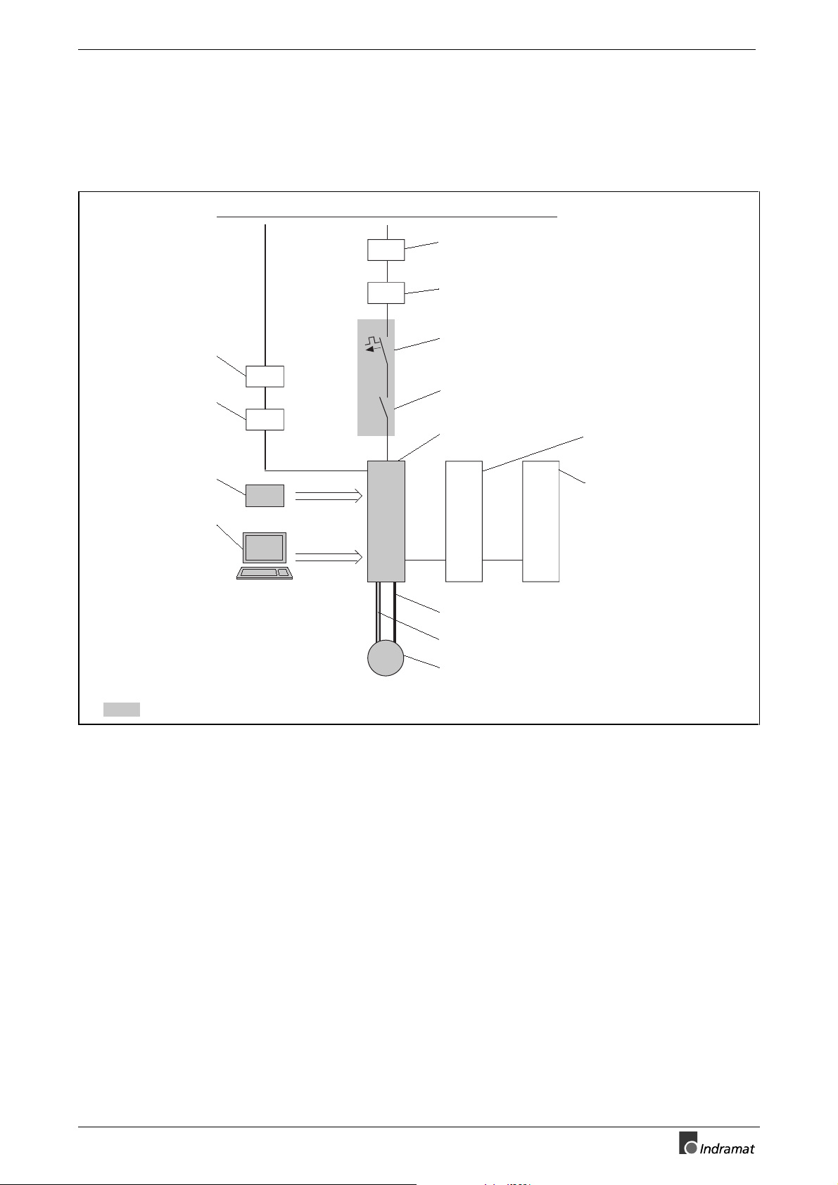
3.1 Overview of the required components
System voltage
Mains filter for
power supply unit
Power supply unit
Firmware
Drive Top
commissioning
program
NFE
NTM
FWA
PC
DC 24 V
NFD
DST
Q1
K1
DKC
MKD
Mains filter for
power connections
Transformer
Fuse
Mains contactor
Drive controller
BZM CZM
IKS - ready-made feedback cable
IKG - ready-made power cable
Servo motor
Auxiliary bleeder module
Auxiliary capacitance
module
Those components shown with a gray-shaded background are absolutely necessary.
Fig. 3-1: Overview of the required components
EB0202D4.fh5
DOK-ECODRV-DKC01/11.1*-PRJ3-EN-P
Page 24

3-2 Selecting the components ECODRIVE DKC01.1/DKC11.1 Drive Controllers
Buy: www.ValinOnline.com | Phone: 844-385-3099 | Email: CustomerService@valin.com
3.2 Selection procedure
Dimensioning and selecting the
servo drive
Compiling the required data
Selecting the required
components
Determining components which
may be additionally required
⇒
Dimension the drive according to how it is to be used. A document f or
this is under preparation.
⇒
Select motor/drive combination (DKC + MKD) using the "Selection
Data" documentation (see pg. 3, supplementary documentation)."
⇒
Enter the values obtained from dim ensioning and enter the drives selected into table Fig. 3-2 .
⇒
Calculate the continuous regenerative power according to the specifications in Chapter 5 and enter them in table Fig. 3-2 .
⇒
Use firmware "FW A-ECODRV-ASE-02VRS-MS" for DKC01.1-*** and
DKC11.1-*** (no selection required at this time)
⇒
"Select ready-made cables for the connection between the DKC and
MKD by using the document "MKD Servomotors - Project Planning
Manual" (see pg. 3 of supplementary documentation)."
⇒
Select fuse protector Q1 (see Chapter 11.2).
⇒
Select line contactor K1 (see Chapter 11.2).
⇒
Check the rated line voltage.
•
If, in the case of the DKC**.*-040-7, the rated line voltage f alls below
or exceeds 3xAC (380-460)V ±10%, select a DST transfor mer (see
Chap. 9.2).
•
If, in the case of the DKC**.*-030-3, the rated line voltage f alls below
or exceeds 3xAC230V ±10%, select a DST transfor mer (see Chap.
9.3).
⇒
Check the DC24V control voltage supply for the DKC. If a voltage of
DC24 Volt ± 20 % is not available, select a suitable NTM power supply
(see Chap. 7).
⇒
Check the DC24V voltage for the m otor holding brake. If a voltage of
DC24 Volt ± 10 % is not available, then select a s uitable NTM power
supply (see Chap. 7).
⇒
Check the continuous regenerative power. If it exc eeds 0.15 kW , then
consider option with BZM auxiliary bleeder module (see Chap. 5).
⇒
Check the peak regenerative power. If it exceeds 5 k W , then consider
option with DKC**.*-040-7 and if needed, the BZM auxiliary bleeder
module (see chapter 5).
⇒
If the continuous regenerative power exceeds appr ox. 0.1 kW and the
drive system energy content is less than 200W, the use of an auxiliary
capacitance module CZM can be econom ical. This mak es it possible
to reduce the dissipated energy for the control cabinet by an amount
equal to the continuous regenerative power (see Chap. 6).
⇒ Check the EMC conditions. INDRAMAT recomm ends the use of NFD
or NFE mains filters to maintain EMC limiting values (see Chap. 8).
DOK-ECODRV-DKC01/11.1*-PRJ3-EN-P
Page 25

ECODRIVE DKC01.1/DKC11.1 Drive Controllers Selecting the components 3-3
Buy: www.ValinOnline.com | Phone: 844-385-3099 | Email: CustomerService@valin.com
3.3 Compiling the required data
Designation Symbol Values/Units
Effective load torque
Acceleration torque
Operating torque
Motor speed used
Load moment of inertia
Maximum rotary energy in the
mechanical system (E-stop case)
Continuous regenerative power
Continuous torque at standstill
Maximum torque
Short-term operation torque
Maximum motor speed
Required power connection ouput
Required mains rated voltage
Motor/controller combination
M
M
M
n
J
W
P
M
M
M
n
S
U
EFF
ACC
BEARB
NUTZ
LAST
RD
DN
MAX
KB
MAX
AN
N
.............................. in Nm
.............................. in Nm
.............................. in Nm
.............................. in min-1
.............................. in kgm²
ROT,MAX
.............................. in Ws
.............................. in kW
.............................. in Nm
............................. in Nm
............................. in Nm
............................. in min-1
............................. in kVA
............................. in V
DKC...................................
Motor moment of inertia
DKC current consumption
Power consumption of the motor
J
I
N,DC
I
N,HB
M
holding brake (if present)
refer to the project planning
manual MKD Motors
Fig. 3-2: Data required for selecting the components
MKD...................................
............................. in kgm²
0.7 in A
............................. in A
DOK-ECODRV-DKC01/11.1*-PRJ3-EN-P
Page 26

3-4 Selecting the components ECODRIVE DKC01.1/DKC11.1 Drive Controllers
Buy: www.ValinOnline.com | Phone: 844-385-3099 | Email: CustomerService@valin.com
Notes
DOK-ECODRV-DKC01/11.1*-PRJ3-EN-P
Page 27
ECODRIVE DKC01.1/DKC11.1 Drive Controllers ECODRIVE DKC drive controllers 4-1
Buy: www.ValinOnline.com | Phone: 844-385-3099 | Email: CustomerService@valin.com
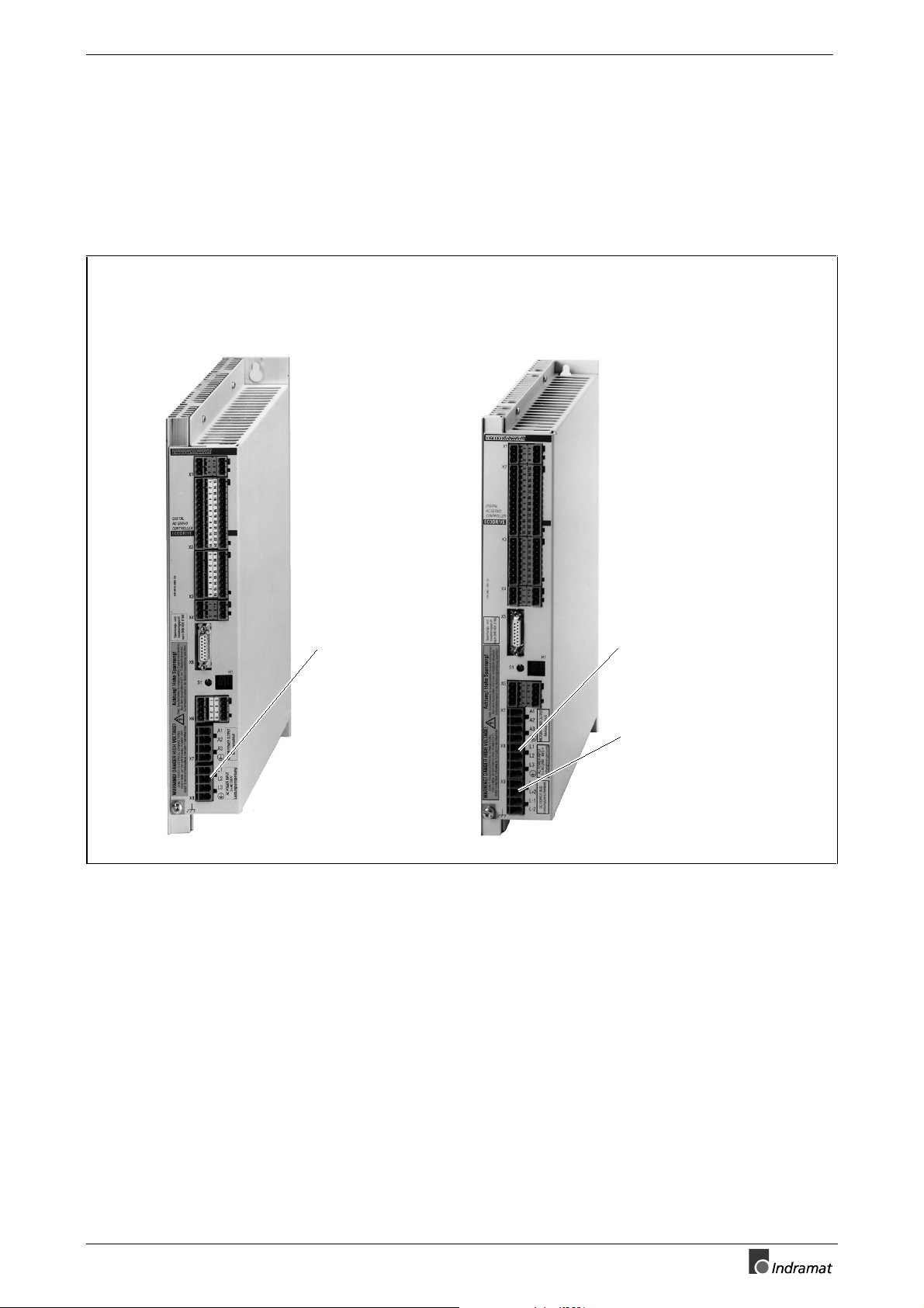
4 ECODRIVE DKC drive controllers
4.1 Hardware
View of unit
DKC**.*-030-3-FW
(I
= 30 A)
Typ
Mains connection
1 x AC 230 V
oder
3 x AC 230 V
DKC**.*-040-7-FW
(I
= 40 A)
Typ
Mains connection
AC (380...460) V
Intermediate circuit connection
for
BZM auxiliary bleeder module
or
CZM auxiliary capacitance module
or
further DKCs
Fig. 4-1: Main distinguishing hardware features of the DKC controllers
PI0200.fh5
DOK-ECODRV-DKC01/11.1*-PRJ3-EN-P
Page 28
4-2 ECODRIVE DKC drive controllers ECODRIVE DKC01.1/DKC11.1 Drive Controllers
Buy: www.ValinOnline.com | Phone: 844-385-3099 | Email: CustomerService@valin.com
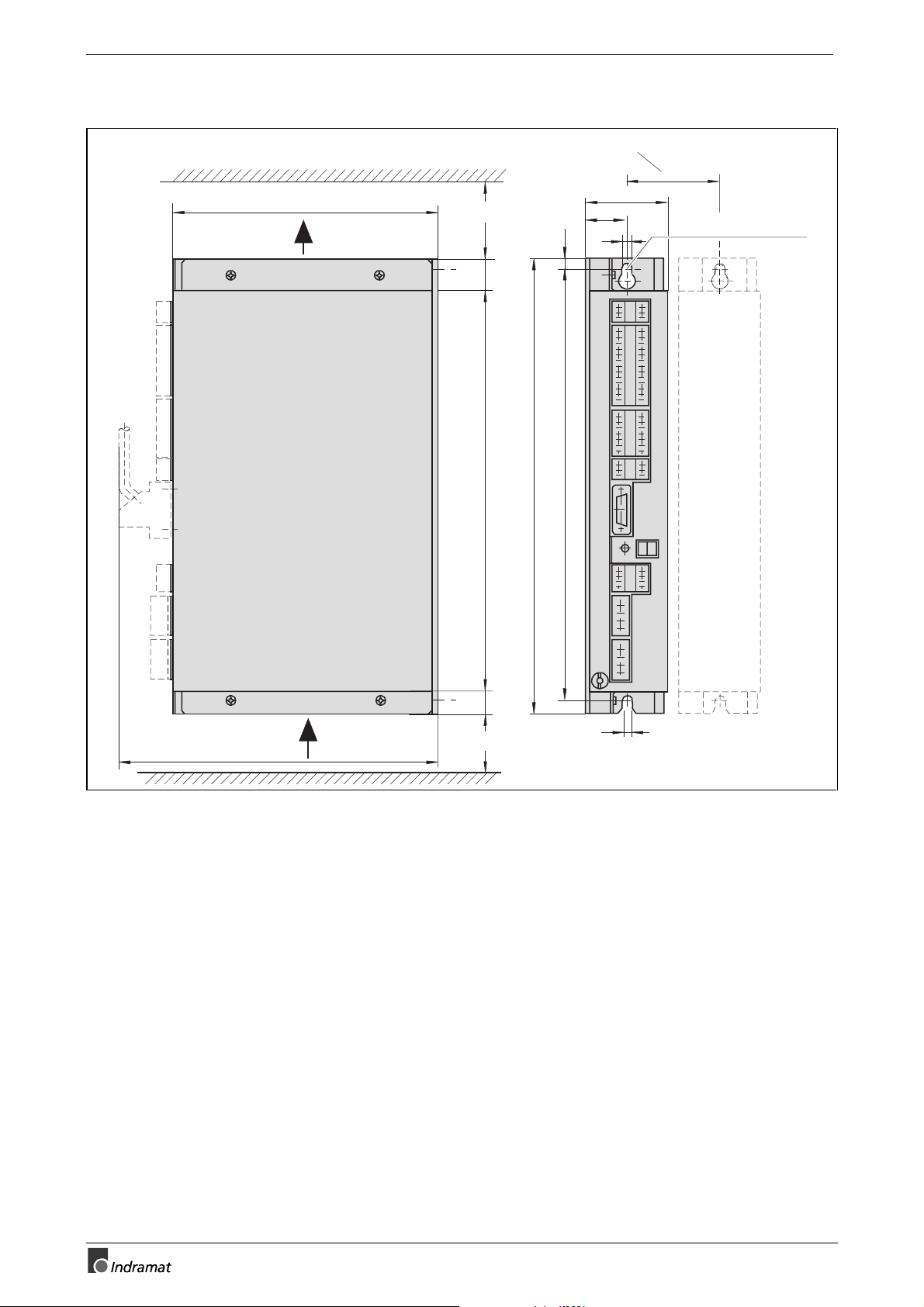
Dimensional sheets and installation dimensions
distance to adjacent unit
70
210
cooling air outlet
min. 80 mm
25
360
8
343
32,5
7
X1
X2
X3
X4
65
M6 in mounting panel
258
X6
S1
X5
H1
X7
X8
318
17
7
cooling air inlet
min. 80 mm
MB0201.fh5
Fig. 4-2: Dimensional data and installation dimensions DKC01.1-030-3-FW
DOK-ECODRV-DKC01/11.1*-PRJ3-EN-P
Page 29
ECODRIVE DKC01.1/DKC11.1 Drive Controllers ECODRIVE DKC drive controllers 4-3
Buy: www.ValinOnline.com | Phone: 844-385-3099 | Email: CustomerService@valin.com
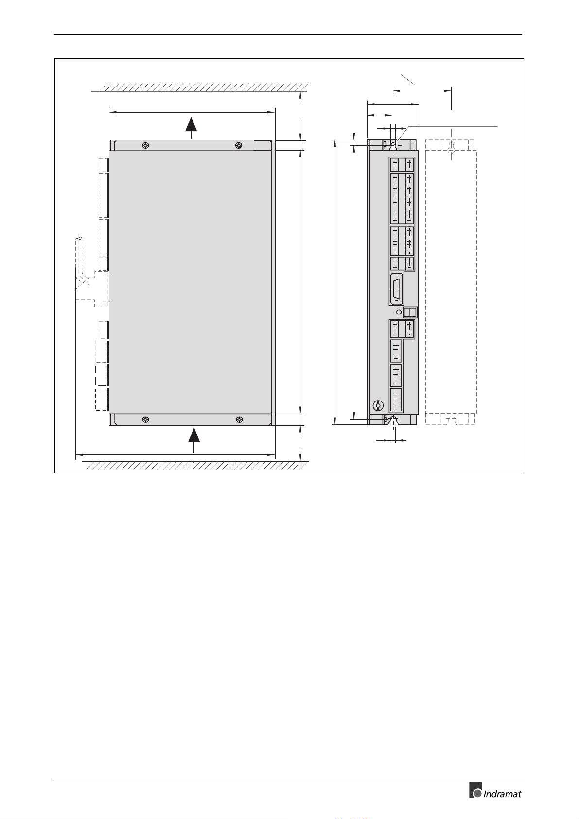
distance to adjacent unit
70
210
cooling air outlet
min. 80 mm
8
32.5
7
65
M6 in mounting panel
258
cooling air inlet
13
333
14
min. 80 mm
360
X1
X2
X3
X4
X5
343
H1
S1
X6
X7
X8
X9
7
MB0202.fh5
Fig. 4-3: Dimensional data and installation dimensions DKC01.1-040-7-
FW/DKC11.1-040-7-FW
DOK-ECODRV-DKC01/11.1*-PRJ3-EN-P
Page 30

4-4 ECODRIVE DKC drive controllers ECODRIVE DKC01.1/DKC11.1 Drive Controllers
Buy: www.ValinOnline.com | Phone: 844-385-3099 | Email: CustomerService@valin.com
Technical data
Power connection / Power section
Designation
Symbol
Unit
Operating mode at the mains
Mains input voltage
Maximum conn. voltage
Making current
Mains frequency
Switching frequency (selectable)
= 4 kHz
Continous current at
Continous current at
f
S
= 8 kHz
f
S
Rated current
Peak current
Power disspation, without
bleeder dissipation
Peak bleeder output DKC
Continous bleeder output DKC
Maximum feedback energy DKC
Storage energy DKC
DC bus capacitance
DC bus voltage
1) The drive data for 4 and 8 kHz switching. frequencies are listed in the document "ECODRIVE DKC servo drive" - Selection Data.
2) Value dependent on power input voltage
2)
U
N
S
MAX
I
EIN
f
N
f
S
1)
I
CONT
1)
I
CONT
I
TYP
I
PEAK
P
V
P
BM,DKC
P
BD,DKC
W
W
C
DKC
U
ZW
MAX,DKC
ZW,DKC
V
kVA
A
Hz
kHz
A
A
A
A
W
kW
kW
kWs
Ws
mF
V
DKC01.1-030-3-FW
single-phase
1 x AC 230
three-phase
3 x AC 230
± 10%
1,8
10
4 or 8
12
11
30
30
100
5 (for 1 s)
0,15
5,0
15
0,15
not lead to the outside
± 10%
3,2
10
DKC**.1-040-7-FW
50...60
three-phase
3 x AC
(380 ... 480)
4,8 ... 9
9 ... 12
4 or 8
16
12,5
40
40
180
10 (for 0,5 s)
0,15
5,0
15
0,15
DC 500...800
± 10%
TB0202.fh5
Designation
Control voltage connection
for DKC
Input voltage
Maximum ripple content
Current consumption
Voltage connection for
holding brake
Input voltage
Maximum ripple content
Current consumption
Fig. 4-4: Technical data for the power connection and power section
DC24V Power supply
N,DC
N,HB
Unit
V
%
A
V
%
A
Symbol
U
w
I
N,DC
U
w
I
N,HB
Fig. 4-5: Technical data for the DC24V power supply
DKC01.1-030-3-FW
DKC**.1-040-7-FW
DC (19,2 ... 28,8) V
must not exceed the input voltage range
0,7
DC 24
± 10%
must not exceed the input voltage range
please see MKD dokumentation
TB0203.fh5
DOK-ECODRV-DKC01/11.1*-PRJ3-EN-P
Page 31

ECODRIVE DKC01.1/DKC11.1 Drive Controllers ECODRIVE DKC drive controllers 4-5
Buy: www.ValinOnline.com | Phone: 844-385-3099 | Email: CustomerService@valin.com
Additional connection of the DC24 power supply
The DKC drives should be firm ly connected to the DC24V power supply;
preferred method Fig. 4-6
They can also be connected to the DC24V power supply in a switchable
manner Fig. 4-7
Preferred method:
The power supply is firmly
connected to the attached DKC
The power supply is connected
to the attached DKC in a
switchable manner
DKC
power supply
L1
24V
X4/1
L2
L3
Q2
0V
DC24V
X4/4
V01DCC1P.fh5
Connecting additional DKC`s
Fig. 4-6: Principle for connecting the DC24V control voltage by switching on the
power supply via Q2, preferred method
DKC
X4/1
X4/4
L1
L2
L3
power supply
DC24V
24V
0V
K1
K1
S1
Rv
K1 closing delay >100 ms, DC1≥10A
Rv = 2,2Ω / 5W (wire resistance)
S1 Cotact, DC1≥ 6 A
Connecting additional DKC x.1,DKC x.2
(max. 6 DKC + 6BZM01.1)
V02DCC1P.fh5
Fig. 4-7: Principle for connection the 24V via S1 with a starting current limiter
DOK-ECODRV-DKC01/11.1*-PRJ3-EN-P
Page 32

4-6 ECODRIVE DKC drive controllers ECODRIVE DKC01.1/DKC11.1 Drive Controllers
Buy: www.ValinOnline.com | Phone: 844-385-3099 | Email: CustomerService@valin.com
Ambient and installation conditions
Ambient temperature and
installation altitude
Selection lists are specified f or each motor/drive documentation. Please
refer to the documentation "ECODRIVE Servodrives DKC with MKD Selection Lists -
The selection lists apply within the given ambient and installation conditions (see Fig. 4-9).
For different conditions, the short-term operating torque is reduced according to the diagrams (see Fig. 4- 8). If deviating am bient temperatur es
and higher installation altitudes occur simultaneously, both load factors
must be multiplied.
Load with higher
ambient temperatures
1
0,8
Load factor
0,6
40 45 50 55
Ambient temperature in °C
1
0,8
Load factor
0,6
00
Load with higher
installation elevations
1000 2000 3000 4000 5000
Installation altitude meters
above sea level
DG0200.fh5
Designation
Ambient and installation
conditions
Cooling the power section
Permissible ambient temperature
with nominal data
Max. permissible ambient
temperature with reduced
nominal data
Storage and transport
temperature
Max. installation elevation
with nominal data
Max. permissible relative humidity
Max. permissible absolute humidity
Degree of contamination
Protection category
Weight
Fig. 4-8: Load utilization as a value dependent upon ambient temperature and
installation altitude
Symbol
T
UM
T
UM,MAX
T
L
Unit
°C
°C
°C
m
%
g/m
DKC01.1-030-3-FW
natural air cooling
3
DKC**.1-040-7-FW
internal blower cooling
+0...+45
+55
The values indicated in the selection data
and MKB, drop in the range of +45
for M
DN
to +55°C by 2% per °C of rise in temperature.
-30...+85
1000
95
25
Non-conductive dirt contamination, no condensation
IP20, as per EN 60529 = DIN VDE 0470-1-1992 (IEC 529-1989)
stationary use in control cabinets
mkg
4.4
TB0204.fh5
Fig. 4-9: Ambient and installation conditions
DOK-ECODRV-DKC01/11.1*-PRJ3-EN-P
Page 33

ECODRIVE DKC01.1/DKC11.1 Drive Controllers ECODRIVE DKC drive controllers 4-7
Buy: www.ValinOnline.com | Phone: 844-385-3099 | Email: CustomerService@valin.com
Type code and rating plate
Type code fields:
Drive controller
Series
Version
Type
30 A
40 A
Rated intermediate circuit voltage
300 V
700 V
Firmware FW
A firmware specifying the functions of the
drive must be ordered separately.
Fig. 4-10: DKC type code
Type of machine
Part no.
DKC01.1-040-7-FW
253158
Example:
DKC
030
040
K16/96
DKC 01.1 - 040 - 7 - FW
01
11
1
3
7
TL0200.fh5
Production week
Barcode
SN253160-01708
Serial number Change index
Fig. 4-11: DKC rating plate
A03
TS0200.fh5
DOK-ECODRV-DKC01/11.1*-PRJ3-EN-P
Page 34

4-8 ECODRIVE DKC drive controllers ECODRIVE DKC01.1/DKC11.1 Drive Controllers
Buy: www.ValinOnline.com | Phone: 844-385-3099 | Email: CustomerService@valin.com
4.2 Firmware
The firmware located in the drive controller determines the functional
features of the ECODRIVE drive controller.
The firmware "FWA-ECODRV-ASE-02VRS-MS" is for the drive controllers DKC01.1-*** and DKC11.1-***.
The firmware has its own order num ber. T his m eans that it is always possible to order the identical firmware version.
The firmware is updated cons tantly to eliminate any bugs without altering
the functionality. It is identified on the type code as the firmware release
version.
If newer functions are added, the index of the f irmware version is incremented (see type codes).
Type codes:
Item i. d.
Firmware
Class
Product (machine)
Name of product
Product: ECODRIVE
Firmware-type
Firmware-Version
02
Firmware type
Test version
Standard
Firmware-release-status (Update)
The status at the time of
delivery.
Language (abbrev. see
INN 09.04, sec. 1)
Multilingual
(alphnumeric)
Example:
FW
ECODRV
ASEParallel interface
(01...99)
FW A-ECODRV-ASE-02 V RS-MS
A
02
T
V
RS
MS
TL0202.fh5
Fig. 4-12: ECODRIVE firmware type code
Firmware-type
Part no.
Barcode
Fig. 4-13: Firmware rating plate
FWA-ECODRV-ASE-02VRS-MS
266285
SN266285-06394
Serial number
Release status
DOK-ECODRV-DKC01/11.1*-PRJ3-EN-P
Production week
K19/96
V01
TS0201.fh5
Page 35

ECODRIVE DKC01.1/DKC11.1 Drive Controllers ECODRIVE DKC drive controllers 4-9
Buy: www.ValinOnline.com | Phone: 844-385-3099 | Email: CustomerService@valin.com
4.3 An overview of the electrical connections
Front view with supply terminals
X1 X1
RS 232 serial
interface
Positioning record
selection or inputs
for stepper interface
Positioning record
acknowledgement
Analog command
value input
Torque reduction
Analog outputs
Control voltage
Controller enable
Drive stop
Motor feedback
connection
Motor temperature
monitoring
Holding
brake control
Motor connection
RxD
TxD
POS1/SM1+
POS2/SM1-
POS3/SM2+
POS4/SM2-
POS5
POS Q1
POS Q2
POS Q3
POS Q4
POS Q5
Shield
IRED1
IRED2
AK1
AK2
Shield
24V
AH/Start
SDI
15
FS
14
R3
13
R1
12
0V
11
10S2
9S1
TM+
TM-
Br+
Br-
A1
A2
A3
0V
0V
RF
1
2
3
X2
1
2
3
4
5
6
7
8
9
10
11
12
X3
E1
E2
0V
1
2
3
4
5
6
7
8
X1
X2
X3
X4
1
2
3
X4
X5
8 SDO
7 SCL
6 R3
5 R1
4 0V
3 S4
2 S3
1 Shield
X6
X7
1
2
3
4
1
2
3
X5
H1
S1
X6
X7
X8
RS 485+
4
RS 485-
5
Shield
6
1)1)
X2
NF
13
NS
14
15
LIMIT+
16
LIMITJOG+
17
JOG-
18
WSP
19
20
INREF
INBWG
21
INPOS
22
23
0V
24
Shield
RS 485 serial
interface
Go to zero point
Zero switch
Travel limit switch
Jog inputs
Path control point
Homing in
Movement in
Position in
X3
UA0+
9
10
11
12
13
14
15
16
UA0UA1+/Data+
UA1-/DataUA2+/CLK+
UA2-/CLK0VM
Shield
X4
0V
4
Bb
5
Bb
6
Actual
position value
(incremental
or SSI)
Ready to operate
Fault clearance button
Diagnosis indicator
X6
24V
5
0V
6
Shield
7
8
Shield
Voltage connection
for holding brake
X8
1
L1
2
L2
3
L3
Power connection
Ground wire connection
X9
and connection for shielding
the motor power cable
X5:
15-pole D-Sub connector (INS 439)
X1, X2, X3, X4, X6:
Screw-down push-in terminals
0.2...2.5 mm², AWG 24-12
X7, X8, X9:
Screw-down push-in terminals
0.2...4 mm², AWG 24-10
1) not on DKC11.1-040-7-FW
Fig.. 4-14: Front view of the DKC with supply terminals
DOK-ECODRV-DKC01/11.1*-PRJ3-EN-P
X9
1
L+1
2
L+2
3
L-1
4
L-2
Intermediate circuit connection
(not on DKC01.1-030-3)
SB0200.fh5
Page 36

4-10 ECODRIVE DKC drive controllers ECODRIVE DKC01.1/DKC11.1 Drive Controllers
Buy: www.ValinOnline.com | Phone: 844-385-3099 | Email: CustomerService@valin.com
Overall connection diagrams
DKC01.1 drive controller
X4
1
contr. volt. for DKC
drive enable
start signal
zero ref. to contr. volt.
ready to
operate
+24V
2
RF
3
AH/Start
4
0V
5
Bb
6
Bb
X2
Positioning
input signals
acknowledge
positioning
input signals
homing
homing switch
travel range
limit switch
Sensor inputs
positive jogging
negative jogging
path switch point
in reference
in motion
in position
1
2
3
4
5
6
7
8
9
10
11
12
13
14
15
16
17
18
19
20
21
22
23
24
POS1
POS2
POS3
POS4
POS5
POS Q1
POS Q2
POS Q3
POS Q4
POS Q5
0V
NF
NS
LIMIT+
LIMITJOG+
JOGWSP
INREF
INBWG
INPOS
0V
X3
1
E1
Feedrate Override
torque
reduction
analog
outputs
output
act. pos. value
(incremental
or SSI)
2
E2
3
IRED 1
4
IRED 2
5
AK1
6
0V
7
AK2
8
9
UA0
10
11
UA0
UA1/Data+
12
UA1/Data-
13
UA2/CLK+
14
UA2/CLK-
15
0V
16
X8
1
L1
power connection
L2
L3
PE
3)
PEprotective conductor
connection
Symbols:
1) Switching capacity DC 24 V/ 2,5 A
2) Specifications for ready-made cables, connectors, and types of cables can be found in the documentation "Connection Accessories for
INDRAMAT drives" cable document no. 209-0050-4399-XX or in the motor project planning manuals.
3) The ground connector of units with discharge currents > 3.5 mA must be at least 10mm2 for mechanical reasons. (DIN VDE 0160/EN 50178)
2
≥
10 mm
Plug-in screw terminal, female
Plug-in screw terminal, male
L1
2
L2
3
L3
in operating mode
POSITIONING interface
1)
Plug-in connector, female
Plug-in connector, male
RxD
TxD
RS485+
RS485-
X5
0V
S3
S1
S4
S2
R1
FS
SCL
SDI
SDO
TM
TMTM+
TM-
0V
Br+
Br-
X1
X7
A1
A2
A3
X6
X9
L+1
L+2
L-1
L-2
1
2
3
4
5
6
4
WH 0,5
GN
2
9
BN
3
PK
GY
1
BN 0,5
1
1
BK
RD
7
1
BU
8
VT
1
1
2
3
GN/YE
4
1
2
3
4
8
7
0V
6
24V
5
+
+
Plug-in terminal
TxD
RS 232-
RxD
interface
0V
RS485+
RS 485interface
RS485-
MKD-
U1
V1
W1
1
2
+
servomotor
X
1
5
3
9
7
Resolver-
10
feedback
2
4
6
8
X1
U1
V1
W1
X2
1
2
+
U
holding brake
AP0200.fh5
2)
2
2
1
2
3
5
6
7
8
voltage connection
for holding brake
DC bus connection
(not with DKC01.1-030-3)
M
3
PTC
Fig. 4-15: DKC01.1 with POSITIONING interface
DOK-ECODRV-DKC01/11.1*-PRJ3-EN-P
Page 37

ECODRIVE DKC01.1/DKC11.1 Drive Controllers ECODRIVE DKC drive controllers 4-11
Buy: www.ValinOnline.com | Phone: 844-385-3099 | Email: CustomerService@valin.com
DKC01.1 drive controller
in operating mode
ANALOG interface
1)
RxD
TxD
RS485+
RS485-
X5
0V
S3
S1
S4
S2
R1
FS
SCL
SDI
SDO
TM+
TM+TM+
TM-
0V
Br+
A1
A2
A3
Br-
L+1
L+2
L-1
L-2
X1
X7
X6
X9
1
TxD
2
RxD
3
0V
4
RS485+
5
RS485-
6
2)
4
2
9
3
10
12
14
7
15
8
1
1
2
3
4
1
2
3
4
8
7
6
5
+
+
2
WH 0,5
GN
BN
PK
GY
2
BN 0,5
BK
RD
BU
VT
1
2
3
GN/YE
5
6
7
8
0V
24V
DC bus connection
(not with DKC01.1-030-3)
RS 232interface
RS 485interface
MKD-
servomotor
X3
1
5
3
9
7
10
2
4
6
8
X1
U1
U1
V1
V1
W1
W1
X2
1
1
2
2
+
+
U
holding brake
voltage connection
for holding brake
Resolverfeedback
M
3
PTC
contr. volt. for DKC
drive enable
start signal
zero ref. to contr. volt.
ready to
operate
homing
homing switch
travel range
limit switch
Sensor inputs
path switch point
analog
com. val. input
torque
reduction
analog
outputs
output
act. pos. value
(incremental
or SSI)
power connection
protective conductor
connection
≥
10 mm
X4
1
+24V
2
RF
3
AH/Start
4
0V
5
Bb
6
Bb
X2
1
2
3
4
5
6
7
8
9
10
11
12
13
14
15
16
17
18
19
20
21
22
23
24
0V
NF
NS
LIMIT+
LIMIT-
WSP
0V
X3
1
E1
2
E2
3
IRED 1
4
IRED 2
5
AK1
6
0V
7
AK2
8
9
10
11
12
13
14
15
16
UA0
UA0
UA1/Data+
UA1/DataUA2/CLK+
UA2/CLK0V
X8
1
L1
L2
L3
PE
3)
PE
2
L1
2
L2
3
L3
Symbols:
1) Switching capacity DC 24 V/ 2,5 A
2) Specifications for ready-made cables, connectors, and types of cables can be found in the documentation "Connection Accessories for
INDRAMAT drives" cable document no. 209-0050-4399-XX or in the motor project planning manuals.
3) The ground connector of units with discharge currents > 3.5 mA must be at least 10mm2 for mechanical reasons. (DIN VDE 0160/EN 50178)
Plug-in screw terminal, female
Plug-in screw terminal, male
Plug-in connector, female
Plug-in connector, male
Fig. 4-16: DKC01.1 with ANALOG interface; Supply terminal assignment
DOK-ECODRV-DKC01/11.1*-PRJ3-EN-P
Plug-in terminal
AP0204.fh5
Page 38

4-12 ECODRIVE DKC drive controllers ECODRIVE DKC01.1/DKC11.1 Drive Controllers
Buy: www.ValinOnline.com | Phone: 844-385-3099 | Email: CustomerService@valin.com
DKC011.1
drive controller with
ANALOG interface
RxD
TxD
0V
RS485+
RS485-
X5
0V
S3
S1
S4
S2
R1
FS
SCL
SDI
SDO
X1
1
TxD
2
RxD
3
0V
4
RS485+
5
RS485-
6
RS 232interface
RS 485interface
MKD-
servomotor
2)
WH 0,5
GN
BN
PK
GY
BN 0,5
BK
RD
BU
VT
2
2
4
2
9
3
10
12
14
7
15
8
1
X3
1
5
3
9
7
10
2
4
6
8
Resolverfeedback
contr. volt. for DKC
drive enable
start signal
zero ref. to contr. volt.
ready to
operate
X4
1
+24V
2
RF
3
AH/Start
4
0V
5
Bb
6
Bb
analog
com. val. input
torque
reduction
analog
outputs
output
act. pos. value
(incremental
or SSI)
power connection
protecxtive conductor
connection
≥
10 mm
X7
X6
X9
1
2
3
4
GN/YE
1
2
3
4
8
7
0V
6
24V
5
+
+
A1
X3
1
E1
2
E2
3
IRED 1
4
IRED 2
5
AK1
6
0V
7
AK2
8
9
10
11
12
13
14
15
16
UA0
UA0
UA1/Data+
UA1/DataUA2/CLK+
UA2/CLK0V
1)
TM+
TM+TM+
TM-
Br+
A2
A3
Br-
X8
1
L1
L2
L3
PE
3)
PE
2
L1
2
L2
3
L3
L+1
L+2
L-1
L-2
U1
1
V1
2
W1
3
5
1
6
2
7
+
8
voltage connection
for holding brake
DC bus connection
X1
U1
V1
W1
X2
1
2
+
U
holding brake
3
M
PTC
Symbols:
1) Switching capacity DC 24 V/ 2,5 A
2) Specifications for ready-made cables, connectors, and types of cables can be found in the documentation "Connection Accessories for
INDRAMAT drives" cable document no. 209-0050-4399-XX or in the motor project planning manuals.
3) The ground connector of units with discharge currents > 3.5 mA must be at least 10mm2 for mechanical reasons. (DIN VDE 0160/EN 50178)
Plug-in screw terminal, female
Plug-in screw terminal, male
Plug-in connector, female
Plug-in connector, male
Fig. 4-17: DKC11.1-040-7-FW with ANALOG interface
Plug-in terminal
AP0205.fh5
DOK-ECODRV-DKC01/11.1*-PRJ3-EN-P
Page 39

ECODRIVE DKC01.1/DKC11.1 Drive Controllers ECODRIVE DKC drive controllers 4-13
Buy: www.ValinOnline.com | Phone: 844-385-3099 | Email: CustomerService@valin.com
DKC01.1 drive controller
X4
1
contr. volt. for DKC
drive enable
start signal
zero ref. to contr. volt.
ready to
operate
+24V
2
RF
3
AH/Start
4
0V
5
Bb
6
Bb
X2
homing
homing switch
travel range
limit switch
Sensor inputs
positive jogging
negative jogging
path switch point
in reference
in motion
in position
1
2
3
4
5
6
7
8
9
10
11
12
13
14
15
16
17
18
19
20
21
22
23
24
SM1+
SM1SM2+
SM2-
0V
NF
NS
LIMIT+
LIMITJOG+
JOGWSP
INREF
INBWG
INPOS
0V
X3
1
E1
Feedrate Override
torque
reduction
analog
outputs
output
act. pos. value
(incremental
or SSI)
2
E2
3
IRED 1
4
IRED 2
5
AK1
6
0V
7
AK2
8
9
UA
10
UA0
11
UA1/Data+
12
UA1/Data-
13
UA2/CLK+
14
UA2/CLK-
15
0V
16
X8
1
L1
L2
power connection
L3
PE
3)
protective conductor
connection
Symbols:
1) Switching capacity DC 24 V/ 2,5 A
2) Specifications for ready-made cables, connectors, and types of cables can be found in the documentation "Connection Accessories for
INDRAMAT drives" cable document no. 209-0050-4399-XX or in the motor project planning manuals.
3) The ground connector of units with discharge currents > 3.5 mA must be at least 10mm2 for mechanical reasons. (DIN VDE 0160/EN 50178)
≥
10 mm
PE
2
Plug-in screw terminal, female
Plug-in screw terminal, male
L1
2
L2
3
L3
in operating mode
STEP MOTOR interface
1)
Plug-in connector, female
Plug-in connector, male
RxD
TxD
RS485+
RS485-
X5
0V
S3
S1
S4
S2
R1
FS
SCL
SDI
SDO
TM
TMTM+
TM-
0V
Br+
X1
X7
A1
A2
A3
Br-
X9
L+1
L+2
L-1
L-2
X6
1
2
3
4
5
6
4
WH 0,5
GN
2
9
BN
3
PK
10
GY
BN 0,5
12
14
BK
RD
7
15
BU
8
VT
1
1
2
3
GN/YE
4
1
2
3
4
8
7
0V
6
24V
5
+
+
Plug-in terminal
TxD
RS 232-
RxD
interface
0V
RS485+
RS 485-
RS485-
interface
MKD-
2)
2
2
1
2
3
5
6
7
8
voltage connection
for holding brake
DC bus connection
(not with DKC01.1-030-3)
Servomotor
U
V
W
1
2
+
X3
1
5
3
9
7
Resolver-
10
feedback
2
4
6
8
X1
U1
V1
W1
X2
1
2
+
U
holding brake
AP0203.fh5
M
3
PTC
Fig. 4-18: DKC01.1 with stepping interface
DOK-ECODRV-DKC01/11.1*-PRJ3-EN-P
Page 40

4-14 ECODRIVE DKC drive controllers ECODRIVE DKC01.1/DKC11.1 Drive Controllers
Buy: www.ValinOnline.com | Phone: 844-385-3099 | Email: CustomerService@valin.com
4.4 Electrical connection to the supply terminal strips
The description of the electrical connections below are f irst grouped according to numbers of the supply terminal strips (e.g. X1, X2 etc.) and
then according to the functions.
Serial interface X1
The serial interface is generally used for programm ing, parameterization
and diagnoses during startup operation and service procedures.
It can be alternatively operated as a RS 232 or RS 485.
RS-232 interface
The RS-232 interface is needed f or program ming, param eterizing and diagnosis during startup operation and service procedures.
It is also used when setting the drive addresses as a requirement for operations via RS-485.
With the RS 232, it is possible to param eterize only one dr ive at a time
when using the DriveTop startup program.
max. 15 meters
cable: IKS 0101
X1
1
RxD
2
TxD
3
0 V
6
5
4
DKC
X1
1
RxD
2
TxD
3
0 V
6
5
4
DKC
PC with 9-pin
D-subminiature
connector
PC with 25-pin
D-subminiature
connector
1)
1)
RxD
TxD
GND
DTR
DSR
RTS
CTS
RxD
TxD
GND
DTR
DSR
RTS
CTS
2
3
5
4
6
7
8
max. 15 meters
cable: IKS 0102
3
2
7
20
6
4
5
1) External shield on PC must be attached to unit chassis.
Fig. 4-19: Connecting a PC to a RS-232 interface on a DKC
AP0224.fh5
DOK-ECODRV-DKC01/11.1*-PRJ3-EN-P
Page 41

ECODRIVE DKC01.1/DKC11.1 Drive Controllers ECODRIVE DKC drive controllers 4-15
Buy: www.ValinOnline.com | Phone: 844-385-3099 | Email: CustomerService@valin.com
RS-485 interface
Interface converter PSM-EG-
RS232/RS485-P/2D
The RS-485 interface is needed f or program ming, param eterizing and diagnosis during startup operation and service procedures.
The RS 485 interface allows :
•
the implementation of a serial bus with up to 31 stations connected by
means of a twisted pair cable (half duplex mode),
•
a transmission length of up to 500 meters
•
data rates of 9600/19200 baud and
•
the implementation of a central PC-based visualization unit.
Via the RS-485 several DKCs can be put into operation with Drive Top
without reconnecting the interface cable.
To operate DriveTop with several ECODRIVEs, a RS- 232/485 converter
is required between the PC and the drives.
The following application example displays a tested assembly with RS485 connection using the Phoenix Contact converter PSM-EG-RS232/
RS485-P/2D.
The Phoenix Contact interface converter PSM-EG-RS232/RS485-P/2D
implements the interface in a way suited for industrial use and for ass embly in cabinets.
twisted wire pair
321 654X132 1
1) Enclosure
180 Ohm / 0,5W
3)
RS 485
RS 232
GND
D (B)
D (A)
2
3
8
2)
654
PC
24V
0V
RS485+
RS485-
DKC
1) The last DKC in series with terminator
2) Connect the outer shield to the PC and converter at the ground
potential (strain relief of the metallized connector shell)
3) The RS 232 interface cable is displayed in figure AP5015
X1
RS485+
RS485-
DKC
AP5017D1.fh5
Fig. 4-20: RS-485 Connecting several DKCs
Note: The cable connection to the equipment mus t not be arranged
in a star topology but must be wired individually from one DKC
to the next.
The RS-485 requires a term inator on both ends. Both the terminator integrated into the interface converter (180 Ohms) and
the pull-up and pull-down resistors (470 Ohm s each) mus t be
activated. The other end of the cable must also be term inated
with a 180 Ohm / 0.5W resistor. The term inator is connected
directly to the DKC, plug X1, pins 4 and 5.
DOK-ECODRV-DKC01/11.1*-PRJ3-EN-P
Page 42

4-16 ECODRIVE DKC drive controllers ECODRIVE DKC01.1/DKC11.1 Drive Controllers
Buy: www.ValinOnline.com | Phone: 844-385-3099 | Email: CustomerService@valin.com
Switch position in the interface
converter
The converter can be modified for various peripherals by using specific
switch positions.
The switch positions shown below must be us ed strictly for the following
wiring diagrams.
•
Switch RS-485 to ON
⇒
180 Ohm circuit termination and 470 Ohms pull-up/down are
connected
•
Switch RS232 to DTE (Data Terminal Equipment)
data direction change-over for RS-485 via RTS
⇒
pin 2: TxD, pin 3: RxD,
•
Set the jumper connection to 3 and 4 data direction change-over polarity
⇒
transmit mode Signal to RTS +3V to +15V
⇒
receive mode Signal to RTS -3V to -15V
RS485 RS232
ON
OFF
18OR
BUS-END
DTE
S1
DCE
23
14
RTS/CTS
RTS/CTS
XX5000D1.fh5
Fig. 4-21: Switch position /jumper position in the interface converter PSM-EG-RS
232 / RS 485-P / 2D
DOK-ECODRV-DKC01/11.1*-PRJ3-EN-P
Page 43

ECODRIVE DKC01.1/DKC11.1 Drive Controllers ECODRIVE DKC drive controllers 4-17
Buy: www.ValinOnline.com | Phone: 844-385-3099 | Email: CustomerService@valin.com
Connecting the RS-232 of the
PCs to the interface converter
The interface converter must be connected via the D- SUB male connector because of the effects of interference.
Interface converter
PSM-EG-RS232/RS485-P/2D
RS232
2
3
7
5
RxD (2)
RTS
GND
metallized
connector
shell
TxD (2)
Interface converter
PSM-EG-RS232/RS485-P/2D
RS232
2
3
7
TxD (2)
RxD (2)
RTS
PC with 9-pin
D-subminiature
connector
RxD
TxD
RTS
GND
1)
metallized
connector
shell
RxD
TxD
RTS
2
3
7
5
3
2
4
Connecting the RS 485 of the
interface converter to the DKC
PC with 25-pin
D-subminiature
connector
1) Connect the outer shield to the PC and converter at the
ground potential (strain relief ot the metallized connector shell)
2) Data direction for switch position S1 = DTE
GND
1)
metallized
connector
shell
7
Fig. 4-22: RS-232 cable (PC interface converter)
twisted wire pair
2
3
8
Interface converter
PSM-EG-RS 232/
RS 485-P/2D
RS485
GND
D (B)
D (A)
metallized
connector
shell
(strain relief)
5
GND
metallized
connector
shell
AP5015d1.fh5
X1
1
2
3
GND
4
RS485+
5
RS485-
6
DKC
AP5016d1.fh5
Fig. 4-23: RS-485 cable (interface converter - DKC)
DOK-ECODRV-DKC01/11.1*-PRJ3-EN-P
Page 44

4-18 ECODRIVE DKC drive controllers ECODRIVE DKC01.1/DKC11.1 Drive Controllers
Buy: www.ValinOnline.com | Phone: 844-385-3099 | Email: CustomerService@valin.com
X2 positioning or stepper interface
Note: Does not apply to the DKC11.1-040-FW!
The cables for the contr ol inputs and status reports r equired for both the
POSITIONING interface and the stepper interface are connected to the
X2/(13-24) supply terminals.
The X2/(1-12) supply terminal is given its function by parameterizing the
operating mode during startup.
•
The positioning blocks are selected at the POSITIONING interface.
•
The signals for the stepper motor control are transmitted via these
terminal strips at the stepper interface.
Control inputs and status reports in the positioning and
stepper interface
Control inputs for referencing
Go to zero point selection
HIGH
Homing point switch
HIGH
0V
ext
Inputs:
Input voltage
Input resistance
HIGH
LOW
6 k 3 10 k
2 k 10 n
max. 20 m
min.
16 V
-0.5 V
approx. 8 kOhm
0,5 mm
0,5 mm
max.
30 V
8 V
2
2
X2
13
14
15
16
17
18
19
20
21
22
23
24
NF
NS
LIMIT+
LIMITJOG+
JOGWSP
INREF
INBWG
INPOS
0V
Fig. 4-24: Inputs for referencing
AP0223.fh5
DOK-ECODRV-DKC01/11.1*-PRJ3-EN-P
Page 45

ECODRIVE DKC01.1/DKC11.1 Drive Controllers ECODRIVE DKC drive controllers 4-19
Buy: www.ValinOnline.com | Phone: 844-385-3099 | Email: CustomerService@valin.com
Control inputs for jog mode
Positive jog
HIGH
Negative jog
HIGH
0V
ext
Inputs:
Input voltage
Input resistance
HIGH
LOW
6 k 3 10 k
max. 20 m
min.
16 V
-0.5 V
approx. 8 kOhm
2 k 10 n
0,5 mm
0,5 mm
max.
30 V
8 V
2
2
X2
13
14
15
16
17
18
19
20
21
22
23
24
NF
NS
LIMIT+
LIMITJOG+
JOGWSP
INREF
INBWG
INPOS
0V
Control inputs for the travel
range limit/sensor inputs
Fig. 4-25: Jog inputs
Positive limit switch
HIGH
Negative limit switch
HIGH
0V
ext
Inputs:
Input voltage
HIGH
LOW
Input resistance
max. 20 m
min.
16 V
-0.5 V
approx. 8 kOhm
0,5 mm
0,5 mm
max.
30 V
8 V
AP0222.fh5
2
2
X2
13
14
15
16
17
18
19
20
21
22
23
24
NF
NS
LIMIT+
LIMITJOG+
JOGWSP
INREF
INBWG
INPOS
0V
6 k 3 10 k
Useful in operating mode Positioning interface
Fig. 4-26: Travel limit switch
DOK-ECODRV-DKC01/11.1*-PRJ3-EN-P
2 k 10 n
AP0221.fh5
Page 46

4-20 ECODRIVE DKC drive controllers ECODRIVE DKC01.1/DKC11.1 Drive Controllers
Buy: www.ValinOnline.com | Phone: 844-385-3099 | Email: CustomerService@valin.com
Status reports
max. 20 m
X2
Path control point
Homing in
Movement in
Position in
0V
ext
Outputs:
Output voltage
HIGH
LOW
Output current I
Rise and fall time
Overload protection
16 V
out
when
output switch to LOW
min.
0 V
out
0,5 mm
max.
U
ext.
1 V
80 mA
ca. µ5 s
> 300 mA the
13
14
15
16
17
2
18
19
20
21
22
23
24
NF
NS
LIMIT+
LIMITJOG+
JOGWSP
INREF
INBWG
INPOS
0V
Fig. 4-27: Status reports
10 k
24 V
(Uext.)
1 n
AP0220.fh5
DOK-ECODRV-DKC01/11.1*-PRJ3-EN-P
Page 47

ECODRIVE DKC01.1/DKC11.1 Drive Controllers ECODRIVE DKC drive controllers 4-21
Buy: www.ValinOnline.com | Phone: 844-385-3099 | Email: CustomerService@valin.com
Positioning interface
Positioning signals and outputs
for acknowledging the
positioning signals
SPS
0V
Inputs:
Input voltage
Input resistance
POS1
POS2
POS3
POS4
200
dig.
I/O
ext
HIGH
LOW
+5 V
5V1 4k7 10k
min.
16 V
-0,5 V
approx. 5 kOhm
max. 20 m
0,5 mm
2
max.
30 V
8 V
X2
1
2
3
4
5
6
7
8
9
10
11
12
POS1
POS2
POS3
POS4
POS5
POS Q1
POS Q2
POS Q3
POS Q4
POS Q5
0V
2k 10n
POS5
6k3 10k
2k 10n
Outputs:
Output voltage
Output current I
HIGH
LOW
out
min.
16 V
0 V
80 mA
max.
U
ext.
1 V
Rise and fall time ca. 5 µs
Overload protection
when
> 300 mA the
out
outputs switch to LOW
24 V
(Uext.)
10k
1n
AP0217.fh5
Fig. 4-28: Connecting the positioning input signals and outputs for acknowledg-
ing the positioning signals
DOK-ECODRV-DKC01/11.1*-PRJ3-EN-P
Page 48

4-22 ECODRIVE DKC drive controllers ECODRIVE DKC01.1/DKC11.1 Drive Controllers
Buy: www.ValinOnline.com | Phone: 844-385-3099 | Email: CustomerService@valin.com
Note: If the inputs POS 1 and POS 2 in Fig. 4-28 are assigned a
LOW signal, 5 volts are applied there. If a PLC is c onnected,
this can cause the control LEDs to r espond. This is prevented
by an interconnected blocking diode in accordance with the
circuit proposal Fig. 4-29.
Control modes via the stepper
interface
Output
SPS
+24 V
Fig. 4-29: Circuit proposal
Stepper interface
1: Quadrature-signals
SM 1
Blocking
diode
1N4148
Inputs DKC
Terminal:X2/1; X2/2; X2/3; X2/4
+5 V
200
4k7
5V1
POS1...POS4
2k 10n
10k
SP0201.fh5
SM 2
2: Forward-backwards-signals
SM 1
SM 2
3: Step and direction singnals
SM 1
SM 2
Left-hand rotation
t1
t1 1,4 µs
³
Left-hand rotation
Left-hand rotation
t
L
tL 2,8 µs
³
t1
t2
t2 5,6 µs
³
t3
t3 5,6 µs
³
Right-hand rotation
Right-hand rotation
Right-hand rotation
SV0200.fh5
Fig. 4-30: Control modes of the stepper interface
DOK-ECODRV-DKC01/11.1*-PRJ3-EN-P
Page 49

ECODRIVE DKC01.1/DKC11.1 Drive Controllers ECODRIVE DKC drive controllers 4-23
Buy: www.ValinOnline.com | Phone: 844-385-3099 | Email: CustomerService@valin.com
Control with differential signals
•
Logical 1 is recognized if a positive differential voltage is applied from
SM+ to SM-.
•
Logical 0 is recognized if a negative differential voltage is applied from
SM+ to SM-.
•
To increase noise im m unity, the differential voltage range should be at
least 2.5 volts. The greater the differential voltage range, the higher
the operational reliability against interference.
Control unit
Channel +
Channel
Channel
Channel
0V
-
+
-
ext
max. 20 m
X2
1
SM1+
2
SM1-
3
SM2+
4
SM2-
5
6
7
8
9
10
11
12
0V
Inputs:
Input voltage
min.
0 V 30 V
Clock frequency
+5 V
200
SM+
SM-
200
+5 V
+15 V
2k
2k 2k
+15 V
max. 175 kHz
2k
4k
Fig. 4-31: Control with differential signals
+
-
max.
22p
50k
AP0219.fh5
DOK-ECODRV-DKC01/11.1*-PRJ3-EN-P
Page 50

4-24 ECODRIVE DKC drive controllers ECODRIVE DKC01.1/DKC11.1 Drive Controllers
Buy: www.ValinOnline.com | Phone: 844-385-3099 | Email: CustomerService@valin.com
Single-channel control via npn
– open-collector outputs (NPN)
Dimensioning the pull-up resistors (2k4 resistors in Fig. 4-32 depends on
the load capability (current, power dissipation) of the open-collector outputs of the control.
Note: Controlling the stepper interface with differential signals is
preferable to single-channel control as the noise immunity of
differential signals is generally better than with zero-referenced
signals.
U
DC +24 V
ext
Control unit
0V
2k4
2k4
2k4
X2
1
SM1+
2
SM1-
3
SM2+
4
SM2-
5
6
7
8
9
10
11
0V
12
Inputs:
Input voltage
min.
max.
0 V 30 V
Clock frequency
+5 V
200
SM+
SM-
200
+5 V
+15 V
2k
2k 2k
+15 V
max. 175 kHz
22p
50k
+
2k
-
4k
Fig. 4-32: Control with open-collector outputs
AP0218.fh5
DOK-ECODRV-DKC01/11.1*-PRJ3-EN-P
Page 51

ECODRIVE DKC01.1/DKC11.1 Drive Controllers ECODRIVE DKC drive controllers 4-25
Buy: www.ValinOnline.com | Phone: 844-385-3099 | Email: CustomerService@valin.com
X3 analog inputs and outputs
The inputs and outputs for operating the analog interf aces are connected
via the supply terminal X3/(1-8).
•
torque reduction
•
setpoint input
•
diagnostics outputs
•
override function for positioning control
The actual position is output either as an increm ental, parallel or absolute
value serial via the X3/(9-16) supply terminal.
Analog interface
Analog setpoint input for
control of speed or torque and
override function
max. 20 m
20k
2
2
min.
±
10 V
±
10 V
20k
+
0,5 mA
ADC 12 Bit
max.
±
15 V
±
15 V
0,5 mm
CNC
0 V
ext
Inputs:
Input voltage
between E1-E2
between E1-0VM; E2-0VM
Input current: E1; E2
Input resistance approx. 20 kOhm
Input drift 18 µV/°C
AD-convertor 12 Bit
Resolution per Bit 4,8 mV
0,5 mm
20k
20k
X3
1
E1
2
E2
3
IRED 1
4
IRED 2
5
AK1
6
0V
7
AK2
8
Fig. 4-33: Analog setpoint input
DOK-ECODRV-DKC01/11.1*-PRJ3-EN-P
AP0213.fh5
Page 52

4-26 ECODRIVE DKC drive controllers ECODRIVE DKC01.1/DKC11.1 Drive Controllers
Buy: www.ValinOnline.com | Phone: 844-385-3099 | Email: CustomerService@valin.com
Torque reduction
max. 20 m
+10V
0 V
0V
M
ext
Inputs:
Input voltage
between IRED1-IRED2
between IRED1-0V; IRED2-0V
Input current: E1; E2
Input resistance approx. 20 kOhm
Input drift 18 µV/°C
AD-convertor 12 Bit
Resolution per Bit 4,8 mV
20k
20k
20k
+
20k
0,5 mm
0,5 mm
min.
±
10 V
±
10 V
2
2
0,5 mA
ADC 12 Bit
max.
±
15 V
±
15 V
X3
1
2
3
4
5
6
7
8
E1
E2
IRED 1
IRED 2
AK1
0V
AK2
Diagnostics outputs
Fig. 4-34: Connecting the analog torque reduction
z. B. oszilloscope
5
CH1 CH2
6
7
8
Outputs:
Output voltage
AK1-0V; AK2-0V
min.
- 10 V
max.
+ 10 V
DA-transformer 8 Bit
Resolution per Bit 78 mV
Fig. 4-35: Connection assignments of the diagnostic outputs
AP0214.fh5
X3
AK1
0V
AK2
AP0212.fh5
DOK-ECODRV-DKC01/11.1*-PRJ3-EN-P
Page 53

ECODRIVE DKC01.1/DKC11.1 Drive Controllers ECODRIVE DKC drive controllers 4-27
Buy: www.ValinOnline.com | Phone: 844-385-3099 | Email: CustomerService@valin.com
Actual position value
electric=one cycle
360°
UA1
Square-wave pulse
UA2
looking onto motor
shaft and with
clockwise rotation
UA0
1
t
1
t
t1 < 50 ns
Fig. 4-36: Signals for the incremental actual position value output
max. 40 m
2
9
10
11
12
13
14
15
16
CNC
Positions interface
-incremental-
0V
0,14 mm
ext
SV0201.fh5
X3
UA0
UA0
UA1
UA1
UA2
UA2
0V
RS422 compatible differential outputs:
Output voltage
HIGH
Output current I
Output frequency
Overload
LOW
out
min.
2,5 V
0 V
max. |20| mA
max. 504 kHz
Do not short-circuit outputs.
Danger of damage!
Fig. 4-37: Incremental actual position value output
max.
5 V
0,8 V
AP0216.fh5
DOK-ECODRV-DKC01/11.1*-PRJ3-EN-P
Page 54

4-28 ECODRIVE DKC drive controllers ECODRIVE DKC01.1/DKC11.1 Drive Controllers
Buy: www.ValinOnline.com | Phone: 844-385-3099 | Email: CustomerService@valin.com
Recommended input circuit for
secondary electronics
Actual position value, in the SSI
format
resolution for 4096 rotations
T
pulse
X 3 C N C
U
a
U
a
RS-422
DIN 66 259, sec. 3
Recommended differential line receiver
AM 26 LS 32
MC 3486
SN 75 ALS 193
SN 75 ALS 195
Fig. 4-38: Recommended input circuit
resolution for 1 rotation
Z
0
Z0 = 120 W
+5V
AP0201.fh5
T
p
data
1 2 3 4 5 6 7 8 9101112131415161718192021222324
G23 G22
G21 G20 G19 G18 G17 G16 G15 G14 G13 G12 G11 G10 G9 G8 G7 G6 G5 G4 G3 G2 G1 G0
m
T
puls
data
G0
G23
m
T
t
m
T
p
t
v
PFB
12
G23 G22
t
v
least significant bit in gray code
=
most significant bit in gray code
=
stored parallel information
=
pulse time max. 10 µs min. 1 µs
=
monoflop time 25 µs
=
pulse break 25 µs
=
delay time of the first pulse max. 540 ns, all others 360 ns
=
=
power failure bit (not used and always logically LOW)
24
G0 PFB
25
25
PFB 0 111
t
m
t
m
-T/2
T
p
SV0202.fh5
12
G23 G221
Fig. 4-39: Pulse timing diagram for absolute actual position value output (SSI
format)
DOK-ECODRV-DKC01/11.1*-PRJ3-EN-P
Page 55

ECODRIVE DKC01.1/DKC11.1 Drive Controllers ECODRIVE DKC drive controllers 4-29
Buy: www.ValinOnline.com | Phone: 844-385-3099 | Email: CustomerService@valin.com
Actual value position SSI
format
CNC
Positioning
interface
-absolute-
0V
ext
RS422 compatible differential outputs:
Output voltage
HIGH
LOW
Output current I
out
Overload protection
RS422 compatible differential inputs:
Input voltage
HIGH
LOW
Input resistor
Pulse frequency
min.
2.5 V
Outputs may not be short-circuited.
Danger of damage!
min.
2 V
max. 20 m
0.5 mm
max. |20| mA
(100-1000) kHz
2
12 kOhm
max.
5 V
0.8 V0 V
max.
5 V
0.8 V0 V
X3
9
10
11
12
13
14
15
16
Data+
DataCLK+
CLK0V
AP0215D4
Fig. 4-40: Output of the absolute actual position value according to the SSI for-
mat
X4 terminals for the control circuit
Control voltage connection for DKC
Zero reference to control votage
Inputs:
Input voltage
Input resistance
Controller enable
Drive stop/start
Ready to
operate
HIGH
LOW
6 k 3 10 k
1
2
3
4
5
6
min.
16 V
-0,5 V
approx. 8 kOhm
X4
+24V
RF
AH/Start
0V
Bb
Bb
max.
30 V
8 V
Fig. 4-41: Terminals for the control inputs, control voltage, and stand-by contact
DOK-ECODRV-DKC01/11.1*-PRJ3-EN-P
2 k 10 n
AP0211fh5
Page 56

4-30 ECODRIVE DKC drive controllers ECODRIVE DKC01.1/DKC11.1 Drive Controllers
Buy: www.ValinOnline.com | Phone: 844-385-3099 | Email: CustomerService@valin.com
X5, X6, X7 motor connections
For the terminal connection assignments to the m otor connections, refer
to the overall connection diagram in Fig. 4-15.
For further inform ation, please see the documentation "ECODRIVE servomotors MKD" - Project Planning Manual -.
X9 DC bus connection
Note: Does not apply to DKC01.1-030-3-FW!
DC bus connection for connecting:
an auxiliary bleeder module BZM01.1
- or -
an auxiliary capacitance module CZM01.1
- or -
a DKC drive controller
The maximum line length is 1.0 m (twisted) with at least a 2.5 m² cross
section.
X9
1
L+1
2
Intermediate circuit connection
on DKC01.1-040-7-FW
on DKC11.1-040-7-FW
Intermediate circuit voltage between L+ and L-: DC (500...800) V
Fig. 4-42: DC bus connection
L+2
3
L-1
4
L-2
AP0206.FH5
DOK-ECODRV-DKC01/11.1*-PRJ3-EN-P
Page 57

ECODRIVE DKC01.1/DKC11.1 Drive Controllers BZM auxiliary bleeder module 5-1
Buy: www.ValinOnline.com | Phone: 844-385-3099 | Email: CustomerService@valin.com
5 BZM auxiliary bleeder module
5.1 Dimensioning the components relevant for regeneration
For each servo-technical application, it is necessary to check whether the
•
continuous regenerative power
•
peak regenerative power
•
regenerative energy
needed for the application can be sufficiently absorbed by the bleeder
(brake resistance).
If the available regenerative power and energy from the mechanics exceeds the absorbing capabilities of the bleeder built into the unit, this capability can be increased on the DKC**.*-040-7-FW by using the following
hardware configurations.
•
A drive and auxiliary bleeder module connected via the DC bus c ircuit.
(1 DKC+BZM)
•
Several drive controllers connected via the DC bus circuit. (up to 6
DKCs)
•
Several drive controllers and auxiliary bleeder modules c onnected via
the DC bus circuit. (up to 6 DKC+BZM)
DOK-ECODRV-DKC01/11.1*-PRJ3-EN-P
Page 58

5-2 BZM auxiliary bleeder module ECODRIVE DKC01.1/DKC11.1 Drive Controllers
Buy: www.ValinOnline.com | Phone: 844-385-3099 | Email: CustomerService@valin.com
1 DKC + BZM
1. Continuous regenerative power
PPP
RD
≤ +
BD, DKC BD,BZM
P
RD
W
ROT
Wmghz
POT LAST
∑∑
=
JJ
+
WW
ROT POT
*1000
t
Z
+
LAST
M
(=
2
= ⋅⋅⋅
2
π
⋅⋅⋅⋅()
nz
NUTZ
AB
2
60
2. Peak regenerative power
PPP
RS
≤ +
BM, DKC BM,BZM
P
RS
- > siehe Auswahldaten zu den Servoantrieben
3. Regenerative energy (a single braking in E-stop)
WW WW
POT, MAX RO T, MAX MAX, DKC MAX, BZM
+ +≤
DEC
W
MAX, DKC
W
MAX, BZM
P
RD : continuous regenerative power from the mechanical system
- > siehe Abb. Technische Daten DKC
- > siehe Abb. Technische Daten BZM
during operation in kW
P
BD, DKC : continuous regenerative power in kW that the drive controller
can process in continuous operation
P
BD, BZM : continuous regenerative power that the auxiliary module can
process in continuous operation, in kW
P
RS : peak regenerative power in kW
W
ROT : rotary energy in Ws
W
POT : potential energy in Ws
W
ROT, MAX : max. occurring rotary energy in an emergency stop in Ws
W
POT, MAX : max. occurring potential energy in an emergency stop (E-stop)
in Ws
t
Z : cycle time in s
J
LAST : load torque in kgm²
J
M : motor inertia, in kgm²
m
LAST: load weight in kg
W
MAX, BZM : storable energy in the BZM in kWs
W
MAX, DKC : storable energy in the DKC in kWs
g
: gravitational acceleration 9.81 ms²
h
: lowering dimension in m
n
: motor speed used in min-1
NUTZ
z
: number of drops per cycle
AB
z
: number of braking actions per cycle
DEC
Fig. 5-1: Check the conditions for regenerative power and regenerative energy
in a DKC connected to a BZM via the DC bus
DOK-ECODRV-DKC01/11.1*-PRJ3-EN-P
Page 59

ECODRIVE DKC01.1/DKC11.1 Drive Controllers BZM auxiliary bleeder module 5-3
Buy: www.ValinOnline.com | Phone: 844-385-3099 | Email: CustomerService@valin.com
up to 6 DKCs
1. Continuous regenerative power
PP
∑∑
RD
≤ 08, *
P
W
Wmghz
BD,DKC
∑∑
WW
ROT POT
=
RD
ROT
= ⋅⋅⋅
POT LAST
t
JJ
()
LAST
2
+
*1000
z
+
π
2
60
2
)
M
nz
(=
⋅⋅⋅⋅
NUTZ
AB
2. Peak regenerative power
PP
∑≤ 08, *
RS
BM,DKC
P
- > siehe Auswahldaten zu den Servoantrieben
RS
3. Regenerative energy (a single braking in E-stop)
DEC
WW W
∑∑ ∑
POT, MAX ROT, MAX MAX, DKC
P
RD : continuous regenerative power of the mechanical system that
+ *
W
MAX, DKC
≤ 08,
- > siehe Abb. Technische Daten DKC
is generated in continuous operation, in kW
P
BD, DKC : continuous regenerated power that the drive controller can
process in continuous operation, in kW
P
RS : peak regenerated power in kW
W
ROT : rotary energy in Ws
W
POT : potential energy in Ws
W
ROT, MAX : max. occurring rotary energy in an E-stop in Ws
W
POT, MAX : max. occurring potential energy in an E-stop in Ws
t
Z : cycle time in s
J
LAST : load torque in kgm²
J
M : motor inertia, in kgm²
m
LAST: load weight in kg
W
MAX, BZM : storable energy in BZM 01.1 in kWs
W
MAX, DKC : storable energy in the DKC in kWs
g
: 9.81 ms²
h
: lowering dimension in m or number of braking actions
n
: motor speed used in min-1
NUTZ
z
: number of drops per cycle
AB
z
: number of braking actions per cycle
DEC
Fig. 5-2: Checking the conditions for regenerative power and regenerative en-
ergy with several DKCs connected via the DC bus
DOK-ECODRV-DKC01/11.1*-PRJ3-EN-P
Page 60

5-4 BZM auxiliary bleeder module ECODRIVE DKC01.1/DKC11.1 Drive Controllers
Buy: www.ValinOnline.com | Phone: 844-385-3099 | Email: CustomerService@valin.com
up to 6 DKCs + BZM
1. Continuous regenerative power
PPP
≤+08, *
RD
∑∑∑
BD, DKC BD, BZM
∑∑
RD
=
P
JJ
W
ROT
Wmghz
= ⋅⋅⋅
POT LAST
+
WW
ROT POT
*1000
t
Z
+
LAST
M
(=
⋅⋅⋅⋅()
nz
2
NUTZ
AB
2
π
2
60
DEC
2. Peak regenerative power
PPP
RS
∑≤+08,*
P
BM, DKC BM, BZM
- > siehe Auswahldaten zu den Servoantrieben
RS
3. Regenerative energy (a single braking in the E-stop position)
WW WW
∑∑ ∑∑
POT, MAX ROT, MAX MAX, DKC MAX, BZM
P
RD : continuous regenerative power of the mechanical system that
+ **
W
MAX, DKC
W
MAX, BZM
≤ 08,
- > siehe Abb. Technische Daten DKC
- > siehe Abb. Technische Daten BZM
occurs in continuous operation in kW
P
BD, DKC : continuous regenerative power that the drive controller can
process in continuous operation in kW
P
RS : peak regenerative power in kW
W
ROT : rotary energy in Ws
W
POT : potential energy in Ws
W
ROT, MAX : max. occurring rotary energy in the E-stop position in Ws
W
POT, MAX : max. occurring potential energy in the E-stop in Ws
t
Z : cycle time in s
J
LAST : load torque in kgm²
J
M : motor inertia, in kgm²
m
LAST: load weight in kg
W
MAX, BZM : storable energy in BZM 01.1 in kWs
W
MAX, DKC : storable energy in the DKC in kWs
g
: 9.81 ms²
h
: lowering dimension in m or number of braking actions
n
: motor speed used in min-1
NUTZ
z
: number of drops per cycle
AB
z
: number of braking actions per cycle
DEC
Fig. 5-3: Check the conditions for regenerative power and regenerative energy in
a DKC connected to a BZM via the DC bus
DOK-ECODRV-DKC01/11.1*-PRJ3-EN-P
Page 61

ECODRIVE DKC01.1/DKC11.1 Drive Controllers BZM auxiliary bleeder module 5-5
Buy: www.ValinOnline.com | Phone: 844-385-3099 | Email: CustomerService@valin.com
5.2 Dimensional data and installation dimensions
Clearance to adjacent units
70
65
32,5
210
min. 80 mm
13
333
360
8
343
7
DIGITAL
AC-SERVO
BLEEDER
ECODRIVE
109-0963-3901-01
X4
H1
H2
S1
RESET
X9
233
14
7
min. 80 mm
Fig. 5-4: Dimensions of the auxiliary bleeding module BZM01.1
L+1
L+2
L-1
L-2
MB0200.fh5
DOK-ECODRV-DKC01/11.1*-PRJ3-EN-P
Page 62

5-6 BZM auxiliary bleeder module ECODRIVE DKC01.1/DKC11.1 Drive Controllers
Buy: www.ValinOnline.com | Phone: 844-385-3099 | Email: CustomerService@valin.com
5.3 Technical data
5.4 Front view
Designation
Continuous bleeder output
(continuous regenerative
Symbol
P
BD,BZM
power when drives are
braked)
Peak bleeder power
P
BM,BZM
(peak regenerative power)
Maximum feedback energy
Control voltage between
X4/1 and X4/4
Current consumption of the
24 V connection
W
MAX,BZM
U
N,BZM
I
N,BZM
Fig. 5-5: Technical data for the BZM
H1 = LED - green:
•
Steady light: auxiliary bleeder functioning properly
•
Flashing light: DC bus < 50V
H2 = LED - red:
•
DIGITAL
AC-SERVO
BLEEDER
ECODRIVE
Steady light: Auxiliary bleeder overload, Bb contact open
S1 = Reset key
X4: Plug-in screw terminal 0.2 to 2.5 mm², AWG 24-12,
rigid or flexible, flexible with or without ring terminals
Unit
kW
kW
kWs
V
mA
Value
1
40
(perm. load cycle on
for 1s, off for 40s)
40
DC 24 V ±20%
90
TB0205.fh5
X4
109-0963-3901-01
H1
H2
S1
RESET
X9 Plug-in screw terminal 0.2 to 4 mm², AWG 24-10,
rigid or flexible
X4
0V
4
Bb
5
6
X4
1
2
3
Ready to operate
Bb
+24 V
Control voltage
free
free
Protective conductor connection
X9
L+1
L+2
L-1
L-2
X9
+
1
+
2
3
4
DC bus connection
-
-
F02DCC1P.fh5
Fig. 5-6: Front view of the auxiliary bleeder module BZM01.1 with supply termi-
nals
DOK-ECODRV-DKC01/11.1*-PRJ3-EN-P
Page 63

ECODRIVE DKC01.1/DKC11.1 Drive Controllers BZM auxiliary bleeder module 5-7
Buy: www.ValinOnline.com | Phone: 844-385-3099 | Email: CustomerService@valin.com
5.5 Electrical connections
Control voltage
connection
DC 24 V± 20%
Ready to operate
Diameter of protective
conductor connection
must correspond to
selection table 11-1
(Fusing)
Fig. 5-7: Connection assignment for the auxiliary bleeding module BZM01.1
5.6 Type code and rating plate
1
2
3
4
5
6
max. DC 24 V/1 A
BZM01.1
X4
+24 V
free
free
0 V
Bb
L+1
++
L+2
L-1
DC bus
connection
DKC**.*-040-7-FW
2
10mm
Protective conductor connection
L-2
X9
≥
max. 1meter,
stranded, 4 mm
X9
L+1
++
2
L+2
L-1
L-2
R01DCC1P.fh5
Type codes:
Auxiliary bleeder module
Series
Version
Nominal Output
1,0 kW
DC bus nominal voltage
700 V
Fig. 5-8: Type code
Part no.
Barcode
Example:
BZM
Type of machine
BZM01.1-01-07
Production week
K21/96
260066
SN260067-00314
B04
Serial number Change index
BZM 01.1 - 01 - 07
01
1
01
07
TL0203.fh5
TS0202.fh5
Fig. 5-9: Rating plate
DOK-ECODRV-DKC01/11.1*-PRJ3-EN-P
Page 64

5-8 BZM auxiliary bleeder module ECODRIVE DKC01.1/DKC11.1 Drive Controllers
Buy: www.ValinOnline.com | Phone: 844-385-3099 | Email: CustomerService@valin.com
Notes
DOK-ECODRV-DKC01/11.1*-PRJ3-EN-P
Page 65

ECODRIVE DKC01.1/DKC11.1 Drive Controllers CZM Auxiliary Capacitance Module 6-1
Buy: www.ValinOnline.com | Phone: 844-385-3099 | Email: CustomerService@valin.com
6 CZM Auxiliary Capacitance Module
6.1 Dimensioning
Note: Only applies to DKC01.1-040-7-FW and DKC11.1-040-7-FW!
When brak ing the drive, the rotary energy available in the mechanics is
released as regenerative energy in the DC bus of the DKC. It can be
•
released in the form of heat via the bleeder module or auxiliary bleeder
integrated into the DKC
- or -
•
stored as energy in the DKC with a connected auxiliary capacitance
module and reused for subsequent acceleration proc edures. This reduces the power dissipated in the cabinet; energy consumption is lowered.
For successf ul implem entation while avoiding an unnecess ary power loss
in the cabinet, note the following:
Calculating the rotary energy of
an application
Storable energy in the DKC with
a connected CZM01.1
WW
Fig. 6-1: Condition for avoiding power dissipation from the regenerative energy
W
ROT
W
ROT : rotary energy of the application in Ws
n
: maximum effective speed in min-1
NUTZ
J
LAST : load torque of the application in kgm²
J
M : motor inertia
Fig. 6-2: Calculating the rotary energy
W
ZW, DKC+CZM
W
ZW, DKC+CZM: storable energy in the DKC with CZM in Ws
C
CZM : capacity of the CZM in mF (value = 1.0 mF)
C
DKC : DC bus capacity of the DKC in mF (value = 0.15 mF)
U
B : UB : Response threshold of the bleeder in DKC in V (value = 820)
U
ZW: nominal voltage (DC bus) in V (UZW = (2 • 0.98 UN)
U
N: line voltage (effective value) in V
Fig. 6-3: Calculating the storable energy with a CZM01.1
≤
ROT ZW, DKC+CZM
+
()
JJ
LAST
CC
M
2
DKC CZM
(=
+
⋅⋅
2
⋅
2
π
2
n
NUTZ
2
UU
( - ) =
⋅⋅
B
60
2
ZW
)
−103
DOK-ECODRV-DKC01/11.1*-PRJ3-EN-P
Page 66

6-2 CZM Auxiliary Capacitance Module ECODRIVE DKC01.1/DKC11.1 Drive Controllers
Buy: www.ValinOnline.com | Phone: 844-385-3099 | Email: CustomerService@valin.com
Application example
n
t
1
R
P
DKC01.-40-7 with AC motor MKD 071 B with the following data:
Designation Value
Rotor inertia of the MKD 071 B
Maximum effective motor speed nNutz = 3200 min-1
Load inertia of the application
Cycle time tZ = 0.8 s
Line voltage
Fig. 6-4: Technical data for application example DKC01.1 with MKD
t
= Accel time in seconds
1
t
= Delay time in seconds
2
t
= Dwell time in seconds
3
= Cycle time in seconds
t
2
t
3
t
z
= Rotary energy in Ws
W
ROT
n = RPM in min
= Peak feedback output in kW
P
RS
P
= Average of the regenerated power
RD
ir a during cycle (continous
regenerated power)
-1
J
M
= 0.00087 kgm²
J
LAST
= 0.00261 kgm²
U
N = 400 V
W
ROT
t
z
t
P
RD
W
ROT
=
t
z
DG0202.fh5
Fig. 6-5: Calculating the regenerative power in the processing cycle
This produces the following results:
W
ROT = 195 Ws
W
ZW, DKC+CZM = 209 Ws
W
ROT ≤
W
This indicates that the condition
ZW, DKC+CZM has been fulf illed. If
the same amount of energy were released via a bleeder, this would r esult
in a continuous regenerative power of 243 W atts as diss ipated power in
the control cabinet due to the cycle time.
DOK-ECODRV-DKC01/11.1*-PRJ3-EN-P
Page 67

ECODRIVE DKC01.1/DKC11.1 Drive Controllers CZM Auxiliary Capacitance Module 6-3
Buy: www.ValinOnline.com | Phone: 844-385-3099 | Email: CustomerService@valin.com
6.2 Dimensional data and installation dimensions
210
min. 80 mm
13
333
360
Clearance to adjacent units
70
65
32,5
7
8
DIGITAL
AC-SERVO
CAPACITOR
ECODRIVE
109-0963-3901-01
343
X9
L+1
L+2
L-1
L-2
233
14
7
min. 80 mm
Fig. 6-6: Dimensions for the auxiliary capacitance modules CZM01.1
MB0203.fh5
DOK-ECODRV-DKC01/11.1*-PRJ3-EN-P
Page 68

6-4 CZM Auxiliary Capacitance Module ECODRIVE DKC01.1/DKC11.1 Drive Controllers
Buy: www.ValinOnline.com | Phone: 844-385-3099 | Email: CustomerService@valin.com
6.3 Front view
DIGITAL
AC-SERVO
CAPACITOR
ECODRIVE
109-0963-3901-01
X9
Fig. 6-7: Front view of the auxiliary capacitance module CZM01.1
6.4 Electrical connection
L+1
L+2
L-1
L-2
CZM01.1
X9 Plug-in screw terminal 0.2 to 4 mm², AWG 24-10,
Protective conductor connection
X9
1
2
3
4
+
+
DC bus connection
-
-
F03DCC1P.fh5
DKC**.*-040-7-FW
2
10mm
≥
L+2
Protective conductor
connection
L+1
X9
++ ++
Fig. 6-8: Connecting the auxiliary capacitance module CZM01.1
L-2
L-1
DC bus
connection
X9
L+1
2
Protective conductor
connection
max. 1meter,
stranded, 4 mm
L-2
L-1
R02DCC1P.fh5
L+2
DOK-ECODRV-DKC01/11.1*-PRJ3-EN-P
Page 69

ECODRIVE DKC01.1/DKC11.1 Drive Controllers CZM Auxiliary Capacitance Module 6-5
Buy: www.ValinOnline.com | Phone: 844-385-3099 | Email: CustomerService@valin.com
6.5 Type code and rating plate
Type code fields:
Auciliary capacitance module
Series
Version
Rated capacity
1,0 mF
DC bus nominal voltage
700 V
Fig. 6-9: Type code
Part no.
Barcode
Example:
CZM
01
1
01
07
Type of machine
CZM01.1-01-07
260068
SN260100-01061
Serial number Change index
Production week
K21/96
A01
CZM 01.1 - 01 - 07
TL0204.fh5
TS0203.fh5
Fig. 6-10: Rating plate
DOK-ECODRV-DKC01/11.1*-PRJ3-EN-P
Page 70

6-6 CZM Auxiliary Capacitance Module ECODRIVE DKC01.1/DKC11.1 Drive Controllers
Buy: www.ValinOnline.com | Phone: 844-385-3099 | Email: CustomerService@valin.com
Notes
DOK-ECODRV-DKC01/11.1*-PRJ3-EN-P
Page 71

ECODRIVE DKC01.1/DKC11.1 Drive Controllers DC24V NTM power supplies 7-1
Buy: www.ValinOnline.com | Phone: 844-385-3099 | Email: CustomerService@valin.com
7 DC24V NTM power supplies
7.1 Application recommendations
If there is no external DC24V control voltage available, then INDRAMAT
recommends the use of NTM power supply units.
Features
•
The power supplies contain an overvoltage safety switch with automatic shutdown. After the autom atic shutdown device has responded,
operation can be resumed by switching the power supply off and on
again briefly.
•
The power supplies always function with a starting current limiter.
However, if you switch on and off again within a period of 10 s, the
starting current limit may not work!
•
The NTM01.1-024-004 and NTM01.1-024-006 power supplies m ake it
possible to measure the voltage applied to the load via sensor c ables.
If there is a voltage drop, the power supply will increase the output
voltage accordingly.
Fuse protector Q2
Interference suppression
7.2 Technical data
Designation
Nominal current of the 24 V output
for the 45°C ambient temperature
Output for 45°C ambient
temperature
Input current at 230 (115) V
Inrush current at 230 (115) V
in the mains supply lead when
powering up. Make sure fuse has
proper size.
Input voltage
RF interference suppression filter
INDRAMAT recommends a 10A automatic circuit breaker of 10 A with
tripping characteristics for the DC24V NTM power supplies.
Use the line filter NFE01.1-250-006 for interference suppression.
OUT
N
Unit
A
W
A
A
V
NTM01.1-024-002
2.1
50
0.61 (1.2)
32 (16)
by rearranging a bridge AC 85...132
(recommended interference suppression filter
NTM01.1-024-004
3.8
100
1.2 (2.2)
32 (16)
Standard AC 170 to 265
NFE01.1-250-006
to maintain EMC values)
NTM01.1-024-006
5.5
150
1.9 (3.2)
32 (16)l
TB0201.fh5
Symbol
I
N
P
I
IN
EIN
U
Fig. 7-1: Technical data for DC24V NTM power supplies
DOK-ECODRV-DKC01/11.1*-PRJ3-EN-P
Page 72

7-2 DC24V NTM power supplies ECODRIVE DKC01.1/DKC11.1 Drive Controllers
Buy: www.ValinOnline.com | Phone: 844-385-3099 | Email: CustomerService@valin.com
7.3 Dimensional data and installation dimensions
7.4 Front views
A
Power supply unit
NTM01.1-024-..
D
Table of dimensions
INDRAMAT
Type of power unit
NTM01.1-024-002
NTM01.1-024-004
NTM01.1-024-006
173
202
212
B
21.9
B
32.130.4
A
A Connecting block
A1
A
168.7
197.7
207.7
B
100
97
97
C
45
51
70
B L-rails DIN 50
D
17
C
20
20
Fig. 7-2: Dimensional sheet DC24V – NTM power supplies
C
CA1
C
> 20 mm
cooling clearance
MB0204.fh5
Potentiometer for fine
adjustments of output
LED green = Output
voltage
voltage applied
Output
voltage
Protective ground
Input
voltage
1)
Pins not connect = input voltage AC (200-240) V
Pins connect = input voltage AC (100-120) V
DC 24 V V+
Zero point V-
FG
L
N
Pins for changing input
voltage
1)
FA0201.fh5
Fig. 7-3: Front view and terminal designations of the power supply NTM01.1-
024-002
DOK-ECODRV-DKC01/11.1*-PRJ3-EN-P
Page 73

ECODRIVE DKC01.1/DKC11.1 Drive Controllers DC24V NTM power supplies 7-3
Buy: www.ValinOnline.com | Phone: 844-385-3099 | Email: CustomerService@valin.com
LED green = output
voltage applied
Output
voltage
Protective ground
Input
voltage
1)
1)
A/B not connected, input voltage AC (170-265) V
A/B connected with bridge, input voltage AC (85-132) V
2)
V+/S+ or V-/S- are connected with bridges
Remove the bridges for using the sensor inputs.
Fig. 7-4: Front view and terminal designation of the power supplies NTM01.1-
7.5 Electrical connection
V+
DC 24 V V+
Zero point V-
V-
FG
L
N
024-004 and NTM01.1-024-006
Potentiometer for fine
adjustments of output
voltage
S+ sensor input
S- sensor input
Input voltage
A
setting
B
via bridge
2)
2)
1)
FA0200.fh5
Always use the NTM together with the line filter NFE01.1-230-006.
Mains sectionRF interference suppression filter
+DC 24 V
0 V
AP0202.fh5
PE
L
N
P
N
E
NFE01.1
-230-006
P'
N'
L
NTM ...
N
V+
V-
Fig. 7-5: Connecting the power supply to a line filter
Note: The bridge circuits V+/S+ and V-/S- must be removed if sen-
sor inputs are used.
Note: The 0 V connection on the secondary side of 24V power sup-
plies is always attached to the central reference ground point
in the control cabinet (see Chap. 8.3)
DOK-ECODRV-DKC01/11.1*-PRJ3-EN-P
Page 74

7-4 DC24V NTM power supplies ECODRIVE DKC01.1/DKC11.1 Drive Controllers
Buy: www.ValinOnline.com | Phone: 844-385-3099 | Email: CustomerService@valin.com
7.6 Type code
Mains section
Load
V+
Input DC 24 V
V-
NTM
S+
S-
Strand sensor line
AP0227.fh5
Fig. 7-6: Connecting the sensor cables NTM01.1-024-004 and NTM01.1-024-
006
Type codes
Power supply module
Series
Version
Output nominal voltage
DC 24 V
Output nominal current
2,1 A
4,2 A
6,3 A
Example:
NTM 01.1 - 024 - 02
NTM
01
1
024
02
04
06
TL0205.fh5
Fig. 7-7: Type code
DOK-ECODRV-DKC01/11.1*-PRJ3-EN-P
Page 75

ECODRIVE DKC01.1/DKC11.1 Drive Controllers NFD / NFE line filter 8-1
Buy: www.ValinOnline.com | Phone: 844-385-3099 | Email: CustomerService@valin.com
8 NFD / NFE line filter
8.1 Selection
The filters listed here are designed for the DKC drive controller power
connection.
Please see Chap. 8.4 for information on the line filter for interference
suppression on the DC24V NTM power supply.
Max. line
power con-
nection volt-
age of the
50..60 Hz
U
N
Rated
line
current
I
Netz
No. of
phases
Type of line fil-
ter
(degree of pro-
tection IP10)
Supply terminals Brush shunt
Power
dissipa
tion
Weight
(1)
in V in A mm
AC 480 V +10% 7,5 3 NFD 02.1-460-008 6 AWG 10 ----- ----- 8,7 1,5
AC 480 V +10% 16 3 NFD 02.1-480-016 6 AWG 10 1,34 16 9 1,7
AC 480 V +10% 30 3 NFD 02.1-480-030 10 AWG 6 5,37 10 14 1,8
AC 480 V +10% 55 3 NFD 02.1-480-055 10 AWG 6 6 13,5 20 3,1
AC 480 V +10% 75 3 NFD 02.1-480-075 25 AWG 3 ----- ----- 20 4
AC 480 V +10% 130 3 NFD 02.1-480-130 50 AWG 1/0 ----- ----- 40 7,5
AC 480 V +10% 180 3 NFD 02.1-480-180 95 AWG 4/0 ----- ----- 61 11
AC 230 V +10% 7,5 1 NFD 02.1-230-008 6 AWG 10 ----- ----- 7,2 1,1
2
AWG mm2AWG in W n kg
(1) = max. continuous current at the power connection at an ambient temperature of 45°C
Fig. 8-1:Technical data of the available line filters
Technical Data
Operating frequency
Power dissipation
Temperature range
Overload
Saturation reaction
from DC to 60 Hz at 40 °C
measured 2 or 3 x R I
2
Nenn DC
-25 ...+ 85 °C
1.5 I
1 min per hour
Nenn
Reduction of the filter attenuation by 6 dB at 2.5 to
3 times the rated current.
Test voltage
Current reduction at
excess temperatures
Degree of protection
L/N -> PE or L -> PE: 2800 VDC 2 s at 25 °C
L -> PE or L -> L: 2125 V
II
in °C ; I
2
=−*( )/85 40
N
in reference to 45°C
N
Θ ; Θ Ambient temperature
2 s or 25 °C
DC
IP 10
Fig. 8-2: Ambient and operating conditions
DOK-ECODRV-DKC01/11.1*-PRJ3-EN-P
Page 76

8-2 NFD / NFE line filter ECODRIVE DKC01.1/DKC11.1 Drive Controllers
Buy: www.ValinOnline.com | Phone: 844-385-3099 | Email: CustomerService@valin.com
8.2 Dimensional data and installation dimensions
E
Load
B
Line
M
NFE 02.1-230-008
NFD 02.1-480-008
K
C
H
D
J
L
G
F
NFD 02.1-480-075
NFD 02.1-480-130
NFD 02.1-480-016
NFD 02.1-480-030
NFD 02.1-480-055
Dimen sion
NFE 02.1-230-008
NFD 02.1-480-008
A
B
C
D
E
F
G
H
J
K
L
M
O
L
-
210
15
0,75
60
40
10
40
90
60
80
5,3
-
H
L
NFD 02.1-480-180
NFD 02. 1 - 480
...-16
142±0,8
305
...-030
335
150±1
55
275±0,8
290
305
320
30
6,5
300
1+0,1
6,5
400
1+0,1
-
9
-
M5
M5
60
35
-
9
-
...-055
329
185±1
80
300
314
55
6,5
500
1,5
-
12
-
M6
...-075
329
220
80
300
314
55
6,5
-
1,5
-
-
-
M6
...-130
429±1,5
240
110±0,8
400±1,2
414
80
6,5
-
1,5
-
-
-
M10
...-180
438±1,5
110±0,8
400±1,2
240
414
50
6,5
500
2
-
15
-
M10
Tolerance
±1
±1,5
±0,6
±1
±0,5
±0,3
±0,2
±15
±0,2
-
±1
-
-
M01DCD1P.fh5
Fig. 8-3: Dimensional data, installation dimensions of the NFD, NFE line filters
DOK-ECODRV-DKC01/11.1*-PRJ3-EN-P
Page 77

ECODRIVE DKC01.1/DKC11.1 Drive Controllers NFD / NFE line filter 8-3
Buy: www.ValinOnline.com | Phone: 844-385-3099 | Email: CustomerService@valin.com
Notes on assembly
The mounting plate or the control cabinet housing to which the DKC is
mounted are the preferred locations for assembly.
Live parts (greater than 50 V)!
Electric shock on contact!
⇒
Before startup operation, the protective ground conductor must first be perm anently connected to the fil-
DANGER
ter and then grounded!
⇒
Before touching bare connection lines and terminals ,
isolate the filter with the connected terminals or disconnect it. Allow time for discharging! Do not work on
connecting cables until then!
⇒
Due to the high discharge current of the f ilter, operation is not permitted without a connected protective
conductor!
⇒
This is why the filter may only be operated with a permanently connected protective conductor with a cross
section ≥10 mm
⇒
Remove any paint or coatings from the mounting
2
!
points of the filter.
⇒
Use a tooth-lock washer with galvanized or tin-plated
screws.
8.3 Electrical connection
To assemble and ins tall the line filters, observe the recom mendations in
the documents
"EMC in Drive and Control Systems"
- Project Planning Manual -
NFE mains filter
L1
1 x AC 230 V
+10% -15%
(50-60 Hz)
L1
N
PE
Q10
L1'
N
PE
PE'
NFE01.1
-230-006
mains filter
N'
2)
Q2
NTM
1)
LINE
LOAD
NL
V+ V-
Q1 :
fuse
Q1
K1
=
central grounding
point within
control enclosure
Q10:
Q2 :
K1 :
power supply
master switch
fuse
control voltage
mains contactor
Control voltage
connection for DKC X4
1) The use of switch-mode power sections (NTM) requires
the preliminary switching of the NFE 01.1-230-006 mains filter
2) Mounting on mounting panel of DKC is recommended
Fig. 8-4: Single-phase line filter connection with NFE02.1-230-008
DOK-ECODRV-DKC01/11.1*-PRJ3-EN-P
Protective conductor
connection ≥ 10mm
Mains connection
X8
2
A03DCC1P.fh5
Page 78

8-4 NFD / NFE line filter ECODRIVE DKC01.1/DKC11.1 Drive Controllers
Buy: www.ValinOnline.com | Phone: 844-385-3099 | Email: CustomerService@valin.com
NFE mains filter
3 x AC
(50-60 Hz)
L1
L2
L3
PE
Q10
L1
L2
L3
E
L1'
L2'
L3'
E'
3)
2)
Q2
NFE01.1
LINE
-230-006
mains filter
NTM
1)
LOAD
N
V+
L
=
V-
Control voltage
connection for DKC X4
Protective conductor
connection ≥ 10mm
1) The use switch-mode power sections (NTM) requires the
preliminary switching of the NFE 01.1-230-006 mains filter
2) AC 230 V connecting voltage (+10% -15%) (50 to 60 Hz)
3) Mounting on mounting panel of DKC is recommended
Fig. 8-5: Three-phase line filter connection with NFD01.1 or NFD02.1
Q1
K1
central
grounding
point
Mains connection
2
X8
Q1 :
fuse
power supply
Q10:
master switch
Q2 :
fuse
control voltage
K1 :
mains contactor
A04DCC1P.fh5
DOK-ECODRV-DKC01/11.1*-PRJ3-EN-P
Page 79

ECODRIVE DKC01.1/DKC11.1 Drive Controllers NFD / NFE line filter 8-5
Buy: www.ValinOnline.com | Phone: 844-385-3099 | Email: CustomerService@valin.com
8.4 Line filters for DC24V NTM power supplies
When using the NT M power supply, use the NFE01.1-250-006 line filter
for interference suppression.
44
43,2
12,4
32,2
11,2
R5
21
54
ø
5,1
0,4
Fig. 8-6: Dimension drawing: Line filter NFE01.1-250-006
Mains side Machine side
NFE01.1-250-006
L1
PE
P
N
N
E
P'
N'
9
15
15
19
MB0206.fh5
AP0228.fh5
8.5 Type code
Fig. 8-7: Contact assignment of the line filter NFE01.1-250-006
The line filter is connected via 6.3-1 tab receptacles in ac cordance with
DIN 462 545.
Type codes:
Mains filter
single phase
three phase
Series
Version
Nominal voltage in V (phase to phase)
230
Rated current in A
Fig. 8-8: Type code
Example:
NFE 01.1 - 230 - 008
NFE
NFD
01
1
230
008
TL0206.fh5
DOK-ECODRV-DKC01/11.1*-PRJ3-EN-P
Page 80

8-6 NFD / NFE line filter ECODRIVE DKC01.1/DKC11.1 Drive Controllers
Buy: www.ValinOnline.com | Phone: 844-385-3099 | Email: CustomerService@valin.com
Notes
DOK-ECODRV-DKC01/11.1*-PRJ3-EN-P
Page 81

ECODRIVE DKC01.1/DKC11.1 Drive Controllers DST / DLT transformers 9-1
Buy: www.ValinOnline.com | Phone: 844-385-3099 | Email: CustomerService@valin.com
9 DST / DLT transformers
9.1 Selection
Transformers are only needed if the line voltage exceeds the permitted
rated voltage of the DKC.
Grounded power supply lines
For grounded power supply lines, the line voltage is matched to the rated
voltage of the unit using autotransformers:
•
for DKC**.*-040-7-FW /DKC11.1-040-7-FW with autotr ansform ers suitable for a specific output voltage range.
•
for DKC**.*-030-3-F with autotransformers designed for a specific
output voltage.
Ungrounded power supply lines
To match the voltage for grounded power supply lines, always connect
isolating transformer s to prevent excess voltages between the outer conductor and ground.
•
for the DKC**.*-040-7-FW this documentation does not offer a range
of products for selecting suitable isolating tr ansformers ( Unterlage bei
Bedarf anfordern).
•
for the DKC**.*-030-3-FW the isolating transformer can be selected
according to Fig. 9-4.
9.2 Autotransformers for DKC**.*-040-7-FW
Select an autotransformer according to the line voltage and the power requirements of the system.
Proceed with the selection as follows:
⇒
Determine the rating group and read the gearing ratio "i" using the required rated line voltage range from the diagram in Fig. 9-1.
⇒
Calculate the actual transformer output voltage using the rated line
voltage and the gearing ratio "i".
⇒
Check drive data. The output voltage of the transformer affects the
drive data. See documentation "ECODRIVE Servodrives DKC with
MKD"- Selection lists.
⇒
Select a three-phase autotransformer via the required connected load.
DOK-ECODRV-DKC01/11.1*-PRJ3-EN-P
Page 82

9-2 DST / DLT transformers ECODRIVE DKC01.1/DKC11.1 Drive Controllers
Buy: www.ValinOnline.com | Phone: 844-385-3099 | Email: CustomerService@valin.com
460
380
Output voltage in V of the transformer
i = 0.52
AC(200...240)V AC(480...500)V
DST**/*/240-460 DST**/*/500-460
0
DG0203.fh5
200
240220 500 520 540 560 580 600 620 640 660 680
i = 1.08
AC(480...580)V
DST**/*/580-460
480
i = 1.26
i = 1.50
AC(570...690)V
DST**/*/690-460
Input voltage in V of the transformer
Fig. 9-1: Classification of three-phase autotransformers into rating groups
700
DOK-ECODRV-DKC01/11.1*-PRJ3-EN-P
Page 83

ECODRIVE DKC01.1/DKC11.1 Drive Controllers DST / DLT transformers 9-3
Buy: www.ValinOnline.com | Phone: 844-385-3099 | Email: CustomerService@valin.com
DST autotransformer with secondary or output voltage AC (380 to 460) V
Standing version for mounting with base: DST..,../S
A
B
Æ
E
F
H
G
C
Type
designation
DST...
Input voltage:
4/S/240-460
7,5/S/240-460
12,5/S/240-460
25/S/240-460
50/S/240-460
Input voltage:
4/S/500-460
7,5/S/500-460
12,5/S/500-460
25/S/500-460
50/S/500-460
Input voltage:
4/S/580-460
7,5/S/580-460
12,5/S/580-460
25/S/580-460
50/S/580-460
Rating plate (example)
GmbH D 97816 Lohr a. M.
DST 20/S/580 - 480
Type
Prim.
480 580 V
Sec.
380 460 V 30 25
S
20 kVA YNa0
Conn.
output
in KVA
AC (200...240) V ±10%
4
7.5
12.5
25
50
AC (480...500) V ±10%
4
7.5
12.5
25
50
AC (480...580) V ±10%
4
7.5
12.5
25
50
T
Trans-
mission
ratio
0.52
1.08
1.26
40/B
A
A
240
335
360
480
580
180
205
240
300
335
240
240
300
360
420
Bj.
1993
f
50/60 Hz
Dimensions in mm
C
B
150
260
175
365
190
395
195
500
265
540
105
190
130
210
140
260
155
325
175
365
130
260
140
260
155
325
190
395
215
450
F
170
230
250
356
400
125
145
170
210
230
170
170
210
250
280
Block diagram
V2
U2
U1
V1
N
1)Temperature switch max. load:
DC 24V/1A; AC 230V/1A
Power
loss
∅
E
110
160
170
----270
80
95
110
140
160
110
110
140
170
190
G
120
145
160
158
215
75
95
110
125
145
100
110
125
160
155
in W
H
120
11
225
11
310
11
500
13
750
18
160
7
260
7
440
11
750
11
1050
11
140
11
260
11
375
11
625
11
1000
14
W2
W1
max.
conn. dia.
in mm
10
10
10
35
70
4
4
10
16
35
4
4
10
10
35
2
a
1)
b
Weight
in kg
24.5
55
70
135
195
8.5
13
22
36
53
18
22
37
72
95
Input voltage:
4/S/690-460
7,5/S/690-460
12,5/S/690-460
25/S/690-460
50/S/690-460
AC (570...690) V ±10%
4
7.5
12.5
1.5
25
50
240
300
335
420
480
140
155
175
205
222
260
325
365
450
500
Fig. 9-2: DST autotransformers for the DKC**.1-40-7-FW to ma tch the line vol t-
age
DOK-ECODRV-DKC01/11.1*-PRJ3-EN-P
170
210
230
280
356
110
140
160
190
-----
110
125
145
145
185
11
11
11
14
13
140
225
375
500
750
10
10
10
16
35
22
37
57
88
178
MB0207.fh5
Page 84

9-4 DST / DLT transformers ECODRIVE DKC01.1/DKC11.1 Drive Controllers
Buy: www.ValinOnline.com | Phone: 844-385-3099 | Email: CustomerService@valin.com
9.3 Autotransformers for DKC**.*-030-3-FW
DST autotransformers with a secondary or output voltage of AC 220...230V
Standing version for foot mounting type: DST.../S
A
E
F
D
Rating plate (example)
Type:
DST 2,5/S/380/415/440-220
Prim.:
380-400/415/440 V
Sec.:
220-230V
S
2,5 kV A
Type designation
DST
0,5/·/380/415/440-220
·
0,5/ /380/460/500-220
·
1,0/ /380/415/440-220
·
1,0/ /380/460/500-220
·
1,5/ /380/415/440-220
·
1,5/ /380/460/500-220
2,0/ /380/415/440-220
·
·
2,0/ /380/460/500-220
·
2,5/ /380/415/440-220
·
2,5/ /380/460/500-220
·
3,5/ /380/415/440-220
·
3,5/ /380/460/500-220
·
4,0/ /380/415/440-220
·
4,0/ /380/460/500-220
·
5,0/ /380/415/440-220
·
5,0/ /380/460/500-220
·
7,5/ /380/415/440-220
·
7,5/ /380/460/500-220
·
10/ /380/415/440-220
·
10/ /380/460/500-220
·
12,5/ /380/415-220
12,5/ /440/460-220
·
12,5/ /500/525-220
·
·
15/ /380/415-220
·
15/ /440/460-220
·
15/ /500/525-220
·
18/ /380/415-220
·
18/ /440/460-220
·
18/ /500/525-220
·
20/ /380/415-220
·
20/ /440/460-220
·
20/ /500/525-220
·
= L, lying version
·
= S, standing version
A
150
150
180
180
180
205
205
240
240
240
240
240
240
240
240
300
300
300
300
300
300
335
335
335
360
360
360
360
360
360
360
420
B
165
165
190
190
190
210
210
260
260
260
260
260
260
260
260
325
325
325
325
325
325
365
365
365
395
395
395
395
395
395
395
450
B
YNa0
B1
170
170
205
205
205
235
235
270
270
270
270
270
270
270
270
340
340
340
340
340
340
380
380
380
400
400
400
400
400
400
400
460
G
C
T 40/B
C
75
90
105
115
115
120
120
120
120
140
140
150
150
155
155
140
155
165
180
195
195
195
195
195
190
190
190
205
205
190
205
215
Æ
H
Bj. 1993
f 50/60 Hz
Dimensions in mm
E
D
C1
70
125
80
95
100
100
110
110
110
135
135
155
155
165
165
170
170
165
180
195
205
220
220
225
225
225
215
215
215
230
230
215
230
210
125
125
150
150
150
170
200
200
200
200
200
200
200
200
250
250
250
250
250
250
280
280
280
300
300
300
300
300
300
300
350
70
80
80
80
95
95
110
110
110
110
110
110
110
110
140
140
140
140
140
140
160
160
160
170
170
170
170
170
170
170
190
Lying version for wall mounting type DST.../L
A
G1
B1
H
G
Æ
V4
V3
V2
V1
Power
dissipation
in W
30
40
45
55
55
75
80
90
95
110
125
130
140
150
160
180
200
230
245
250
260
270
285
290
305
310
330
350
375
380
395
430
W4
W3
W2
W1
Max. connec.
in cross sect.
in mm
10
10
10
10
10
10
10
10
10
10
10
10
10
16
16
16
16
16
16
16
16
16
E
F
D
Connection diagram
440V
415V
380V
220V
1) Max. loading of temperature switch:
DC 24V/1A; AC 230V/1A
F
100
100
125
125
125
145
145
170
170
170
170
170
170
170
170
210
210
210
210
210
210
230
230
230
250
250
250
250
250
250
250
280
G1
154
154
185
185
185
209
209
240
240
240
240
240
240
240
240
310
310
310
310
310
310
350
350
350
370
370
370
370
370
370
370
420
400V
230V
U4
U3
U2
U1
N
Æ
H
6
55
6
70
7
75
7
85
7
85
7
85
7
85
11
90
11
90
11
110
11
110
11
120
11
120
11
125
11
125
11
110
11
125
11
135
11
150
11
165
11
165
11
160
11
160
11
160
11
160
11
160
11
160
11
175
11
175
11
160
11
175
14
165
C1
a
1)
b
Wght.
in kg
4
4
4
4
4
4
4
4
4
4
4
6
8,5
10
10
11,5
11,5
18
18
21
21
24,5
24,5
26
26
30,5
36
42
50
53
53
65
65
65
68
68
68
80
80
70
80
92
MB0208.fh5
Fig. 9-3: Three-phase autotransformers for the DKC01.1-030-3-FW for con-
necting to power supply lines > 230 V
DOK-ECODRV-DKC01/11.1*-PRJ3-EN-P
Page 85

ECODRIVE DKC01.1/DKC11.1 Drive Controllers DST / DLT transformers 9-5
Buy: www.ValinOnline.com | Phone: 844-385-3099 | Email: CustomerService@valin.com
DST autotransformers with a secondary or output voltage of AC 220...230V
Standing version for foot mounting type: DST.../S
A
B
Lying version for wall mounting type DST.../L
A
B1
G1
C1
E
F
D
Rating plate (example)
Type:
DLT 2,5/S/380/415/440-220
Prim.:
380-400/415/440 V
Sec.:
220-230V
S
2,5 kV A
Type designation
DLT
·
0,5/ /380/415/440-220
·
0,5/ /380/460/500-220
1,0/ /380/415/440-220
·
1,0/ /380/460/500-220
·
1,5/ /380/415/440-220
·
·
1,5/ /380/460/500-220
·
2,0/ /380/415/440-220
·
2,0/ /380/460/500-220
·
2,5/ /380/415/440-220
·
2,5/ /380/460/500-220
·
4,0/ /380/415/440-220
·
4,0/ /380/460/500-220
·
5,0/ /380/415/440-220
·
5,0/ /380/460/500-220
·
7,5/ /380/415/440-220
·
7,5/ /380/460/500-220
·
10/ /380/415/440-220
·
10/ /380/460/500-220
·
15/ /380-220
·
20/ /380-220
·
= L, lying version
·
= S, standing version
Yyn0
A
180
180
205
205
240
240
240
240
300
300
300
300
335
335
360
360
360
360
420
420
T 40/B
B
190
190
210
210
260
260
260
260
325
325
325
325
365
365
395
395
395
395
450
450
Bj. 1993
f 50/60 Hz
B1
205
205
235
235
270
270
270
270
340
340
340
340
380
380
400
400
400
400
Hø
G
C
Dimensions in mm
C
C1
105
100
105
100
130
120
130
120
140
155
140
155
150
165
150
165
140
165
140
165
165
195
165
195
175
210
175
210
190
215
190
215
205
230
205
230
245
275
E
F
D
Connection diagram
G
75
75
95
95
110
110
120
120
110
110
135
135
145
145
160
160
175
175
195
225
1U1
1U2
1U3
1V1
1V2
1V3
1W1
1W2
1W3
G1
185
185
209
209
240
240
240
240
310
310
310
310
350
350
370
370
370
370
1U1, 1V1, 1W1
1U2, 1V2, 1W2
1U3, 1V3, 1W3
2U1, 2V1, 2W1
1) Max. loading of temperature switch:
DC 24V/1A; AC 230V/1A
D
150
150
170
170
200
200
200
200
250
140
250
140
250
140
250
140
280
160
280
160
300
170
300
170
300
170
300
170
350
190
400
190
80
80
95
95
110
110
110
110
E
440 V
415 V
380 V. V
220 V. V
F
125
125
145
145
170
170
170
170
210
210
210
210
230
230
250
250
250
250
280
280
Hø
Hø
7
7
7
7
11
11
11
11
11
11
11
11
11
11
11
11
11
11
16
16
Power
dissipation
in W
65
70
120
140
155
165
180
195
220
235
240
265
300
350
375
395
500
510
600
800
2U1
a
2V1
1)
2W1
b
2N1
Max. connec.
in cross sect.
in mm
2
4
4
4
4
4
4
4
4
4
4
10
10
10
10
10
10
10
10
16
35
MB0209.fh5
Wght.
in kg
8,5
8,5
13
13
21
21
24,5
24,5
30,5
30,5
42
42
55
55
70
70
85
85
122
152
.
Fig. 9-4: Three-phase isolating transformer documentation for the DKC01.1-
030-3-FW for connecting to power supply lines > 230 V (ungrounded
power supply lines)
DOK-ECODRV-DKC01/11.1*-PRJ3-EN-P
Page 86

9-6 DST / DLT transformers ECODRIVE DKC01.1/DKC11.1 Drive Controllers
Buy: www.ValinOnline.com | Phone: 844-385-3099 | Email: CustomerService@valin.com
9.4 Electrical connection of the DKC via transformer
Power connection on X8:
DKC
3 x AC 380...480 V bei DKC 01.1-040-7-FW
3 x AC 380...480 V bei DKC 11.1-040-7-FW
3 x
AC 230 V bei DKC 01.1-030-3-FW
Mains filter
NFD
L1'
L2'
L3'
E'
Q1
2
(EN 50178)
PE
3 x AC
50...60 Hz
L1
L2
L3
1) Protective conductor connection ≥ 10mm
1)
DST
X8
K1
L1L2L3
123
Fig. 9-5: Power connection via a three-phase autotransformer
DKC01.1-030-3
Power connection on X8:
L1 L2 L3
X8
1 x AC 230 V bei DKC 01.1-030-3-FW
Mains filter
1 x AC
50...60 Hz
PE
L1
N
PE
L1'
N'
Q1
NFE
1) Protective conductor connection ≥ 10mm2 (EN 50178)
1)
123
K1
PE
L1
L2
L3
PE
L1
N
Power
connection
for further
DKCs
AP0234.fh5
Power
connection
for further
DKCs
AP0235.fh5
Fig. 9-6: Direct power connection via single-phase via autotransformer
DOK-ECODRV-DKC01/11.1*-PRJ3-EN-P
Page 87

ECODRIVE DKC01.1/DKC11.1 Drive Controllers DST / DLT transformers 9-7
Buy: www.ValinOnline.com | Phone: 844-385-3099 | Email: CustomerService@valin.com
9.5 Type code
Type code fields:
Product group
Three-phase autotransformer
Three-phase isolating autotransformer
Rated power in kVA
20 kVA
Mounting style
horizontal mounting
vertical mounting
Rated output voltage
AC 380 V; AC 415 V
Rated output voltage
AC 230 V
Connection symbol
YYNO
Example:
(phase to phase)
(phase to phase)
Fig. 9-7: Type code for transformers
DST
DLT
20,00
380,415
220
YYNO
DST 20,00/S/380,415-220-YYNO
L
S
TL0201.fh5
DOK-ECODRV-DKC01/11.1*-PRJ3-EN-P
Page 88

9-8 DST / DLT transformers ECODRIVE DKC01.1/DKC11.1 Drive Controllers
Buy: www.ValinOnline.com | Phone: 844-385-3099 | Email: CustomerService@valin.com
Notes
DOK-ECODRV-DKC01/11.1*-PRJ3-EN-P
Page 89

ECODRIVE DKC01.1/DKC11.1 Drive Controllers Planning the control cabinet 10-1
Buy: www.ValinOnline.com | Phone: 844-385-3099 | Email: CustomerService@valin.com
10 Planning the control cabinet
10.1 Notes on installing the control cabinet
All ECODRIVE drive components -- with the exception of the motors -are designed to be installed into a control cabinet. When planning the
control cabinet, it is necessary to take the tec hnic al data of the dr ive c omponents into account.
Power dissipation
Power dissipation is determined by the current load and the continuous
regenerative power. The actual power dissipation is dependent on the respective cycle load. The servomotor im plemented has been laid out for
this load cycle.
I
On the average, the continuous current at standstill
the drive controller as a maximum value.
dN will flow through
Determining power dissipation
⇒
See the respective document "ECODRIVE Ser vomotors MKD" - Proj-
I
ect Planning - for the continuous current at standstill
⇒
Using the
I
dN value of the motor selected, find the value in the diagram
in Fig. 10-1 for the current-dependent power dissipation
⇒
Convert the continuous regenerative power found in Tab. Fig. 3-2 with
the factor 0.8. as bleeder-dependent power dissipation
dN.
P
V, DKC.
P
V, Bleeder in the
DKC.
⇒
Add both dissipation values (
P
V,DKC and PV,Bleeder). Use the total (PV,ges)
for planning the control cabinet.
200
180
160
140
in W
V
120
P
100
80
60
40
Power loss
20
0
4812
Continuous current with motor at standstill
I
in A
dN
16
DG0201.fh5
Fig. 10-1: Determining the power dissipated in the control cabinet
DOK-ECODRV-DKC01/11.1*-PRJ3-EN-P
Page 90

10-2 Planning the control cabinet ECODRIVE DKC01.1/DKC11.1 Drive Controllers
Buy: www.ValinOnline.com | Phone: 844-385-3099 | Email: CustomerService@valin.com
10.2 Using heat-exchange units in the control cabinets
Improperly installed and operated heat-exchange units are a risk to the
drive components installed in the contr ol cabinet due to the condensation
and condensed water which these may cause!
Risk of condensation
Risk of condensation
Avoiding condensation
Humid air enters the cabinet and, as it cools, condenses onto the installed
drive components.
If the heat-exchange unit is not properly installed in the control cabinet,
accumulating condensed water can drip into the installed drive components or be sprayed into them by the cold air current.
Proper use of the heat-exchange units:
•
When using heat heat-exchange units, the cabinets must be well
sealed so that moisture cannot f orm caused by humid outside air entering the cabinets!
•
In the event that the control cabinets are operated with open doors
(startup operation, servicing, etc.), ens ure that the drive components
are never cooler than the air in the control cabinets after the doors
have been closed. Otherwise, condensation may occur. For this reason, it is important that the heat-exchange unit continues to operate
when the system has been shut down to ensure that temperature
within the control cabinet does not deviate from that of the drive com ponents.
•
Set the heat-exchange unit to a permanent tem perature of 40 °C. Not
lower!
•
Heat-exchangers with follow-up temperature m ust be set so that the
temperature inside the cabinet is never lower than the outside temperature. Set the temperature limit to 40 °C!
Avoiding dripping and sprayed
water
Summary
The heat-exchange units m us t be arr anged in s uch a way that condensed
water that may accumulate cannot drip into the installed drive components. Units on top of the cabinet require a special design!
Make sure that the control cabinet is c onstructed in such a way that the
blower of the cooling unit cannot spray condensed water which m ay have
collected, onto the drive components!
•
Ensure that no condensed water can drip into the installed drive components!
•
Make sure that the temperature of the heat-exchange unit has been
properly set!
DOK-ECODRV-DKC01/11.1*-PRJ3-EN-P
Page 91

ECODRIVE DKC01.1/DKC11.1 Drive Controllers Planning the control cabinet 10-3
Buy: www.ValinOnline.com | Phone: 844-385-3099 | Email: CustomerService@valin.com
correct
Cooling system
warm cold
incorrect
Cooling system
warm cold
Air duct
electronic
equipment
Cabinet
electronic
equipment
Cabinet
EB0200.fh5
Fig. 10-2: Arranging the heat-exchange unit on the top of the control cabinet
correct
Cabinet
Air inlet
Air
incorrect
Cabinet
Air inlet
Air outlet
duct
Cooling
system
electronic
equipment
Cooling
system
electronic
equipment
EB0201.fh5
Fig. 10-3: Arranging the heat-exchange unit at the front of the control cabinet
DOK-ECODRV-DKC01/11.1*-PRJ3-EN-P
Page 92

10-4 Planning the control cabinet ECODRIVE DKC01.1/DKC11.1 Drive Controllers
Buy: www.ValinOnline.com | Phone: 844-385-3099 | Email: CustomerService@valin.com
Notes
DOK-ECODRV-DKC01/11.1*-PRJ3-EN-P
Page 93

ECODRIVE DKC01.1/DKC11.1 Drive Controllers Power connection 11-1
Buy: www.ValinOnline.com | Phone: 844-385-3099 | Email: CustomerService@valin.com
11 Power connection
11.1 Direct power connection
DKC01.1-040-7-FW
DKC11.1-040-7-FW
DKC01.1-030-3-FW
It is possible to connect these drives directly to grounded three-phase current lines with AC 380...480 V, +10 %. Only a fuse protector Q1, a m ains
contactor K1, and normally a line filter are required in the power input line.
If the line voltage exceeds the permitted input voltage range, then the
voltage must be matched by means of an autotrans former which, in tur n,
has also been laid out for a specific voltage range (see Chapter 9-1).
It is possible to connect these drives directly to grounded three-phase current lines with 3 x AC 230 V, +10 %. A single-phase power connection 1 x
AC 230V is possible for small amounts of power.
Only a fuse protector Q1, a line contactor K1, and nor mally a line filter are
required in the power input line.
If the line voltage deviates from the per mitted input voltage, the voltage is
usually matched using an autotransform er or for special line conditions,
using an isolating transformer (see Chapter 9-1).
DKC01.1-030-3
DKC01.1-040-7
DKC11.1-040-7
NFD
Mains filter
L1
3 x AC
50...60 Hz
1) Protective conductor connection ≥ 10mm
L2
L3
PE
L1'
L2'
L3'
1)
E'
2
Q1 K1
X8
L1L2L3
123
L1
L2
L3
PE
Power
connection
for further
DKCs
AP0232.fh5
DOK-ECODRV-DKC01/11.1*-PRJ3-EN-P
Fig. 11-1: Direct three-phase power connection
X8
1)
NFE
Mains filter
L1
1 x AC
50...60 Hz
PE
1) Protective conductor connection ≥ 10mm
L1
L1'
N
N
N'
PE'
PE
Q1
2
Fig. 11-2: Direct single-phase power connection
DKC01.1-030-3
L1L2L3
123
K1
L1
N
PE
Power
connection
for further
DKCs
AP0233.FH5
Page 94

11-2 Power connection ECODRIVE DKC01.1/DKC11.1 Drive Controllers
Buy: www.ValinOnline.com | Phone: 844-385-3099 | Email: CustomerService@valin.com
11.2 Line contactor/fuse protector
A selection table (see Fig. 11-6) is available to facilitate the selection of a
suitable line contactor and fuse protector device for the power connection.
Calculating the phase current at the power connection
To be able to select a suitable line contactor and suitable power c onnection fuse protector, the phase current IN at the power connection must
first be calculated.
S
The apparent power
is used to determine the phase curr ent
power connection.
Locate the apparent power in the selection table of the drive com ponents,
or calculate it according to formula Fig. 11-4. For several drive contr oller s,
add the individual apparent power values.
I
N at the
Mn
⋅⋅
P
DC
P
DC: DC bus power in W
M
EFF: Effective torque in Nm
n
MITTEL: Average speed in min-1
k
: Factor for motor and controller efficiency = 1.25
Fig. 11-3: Calculating the DC bus power
F
: Factor for the connected load
F
: 2.6 for
F
: 1.95 for
Fig. 11-4: Calculating the power connection output
P
DC = 500 W
P
DC = 2000 W
EFF MITTEL
=
60
SPF
= ⋅
AN DC
Single-phase connection:
I
N
2
=
π
k
⋅
S
AN
U
N
Three-phase connection:
I
N: Phase current at the power connection in A
S
AN: Power connection output in VA
U
N: Voltage between the phases of the power supply lines in V
Fig. 11-5: Calculating the phase current at the power connection
S
U
N
AN
⋅ 3
I
=
N
DOK-ECODRV-DKC01/11.1*-PRJ3-EN-P
Page 95

ECODRIVE DKC01.1/DKC11.1 Drive Controllers Power connection 11-3
Buy: www.ValinOnline.com | Phone: 844-385-3099 | Email: CustomerService@valin.com
Selecting fuse protector Q1 and line contactor K1
Phase
current
I
N
in A
Fuse protector Q1
Line contactor K1
Selection table
Line
cross
section
(1)
2
mm
Automatic
breaker
(tripping char-
acteristic C)
Cur-
rent
in A
circuit
The fuse protector m ust be rated 1.5 times higher than the actual current
I
at the power connection
N.
Fuse protection can be implemented using:
•
an automatic circuit breaker (power circuit breaker) or
•
a power circuit breaker or
•
safety fuses.
Select the line contactor according to the phase c urrent at the power connection and the rated line voltage.
The rated current of the line contactor m ust be 1.5 times higher than the
actual phase current at the power connection.
For a rated line voltage of 3 x 400 V, 50 Hz, , the line contactors listed in
the selection table are recommended depending on the phase current
The types specified in the selection table are fr om the Siemens company
and serve as examples. Sim ilar products from other m anufacturers can
also be used.
Recommended fuse protection Recommended line
contactor
N
(3)
Power circuit breaker Safety fuse
Siemens
type
Setting
value in
A
N
(3)
(class gl)
Cur-
rent
in A
N
(3)
(for
U
Siemens
type
N = 3 x 400 V, 50
Hz)
Nominal
operating
current
N
(3)
I
N.
up to
8.7
up to
11
up to
15
up to
21
(1) Values apply to PVC insulated multi-wire cables in protective pipes and installation ducts with an ambient te m-
perature of 45 °C (compliant to EN 60204-1/1992)
(2) The current was fixed based on operating mode AC 3 for a line voltage of AC 400 V, 50 Hz.
(3) N = maximum number of connectable drives taking the starting current into consideration. If more drives are
connected than indicated, a fuse protector or line contactor with a higher current rating must be selected.
1,0 10 5 3VU1300
- .ML00
1,5 16 7 3VU1300
- .MM00
2,5 20 9 3VU1300
- .MP00
4,0 32 15 3VU1300
- .MP00
Fig. 11-6: Selection table for fuse protector Q1 and line contactor K1
10 12 10 4 3TF40 12 7
16 19 16 6 3TF41 16 10
20 24 20 9 3TF42 22 13
25 30 32 14 3TF43 32 19
DOK-ECODRV-DKC01/11.1*-PRJ3-EN-P
Page 96

11-4 Power connection ECODRIVE DKC01.1/DKC11.1 Drive Controllers
Buy: www.ValinOnline.com | Phone: 844-385-3099 | Email: CustomerService@valin.com
11.3 Control circuit to the power connection
The control circuit recommended by INDRAMAT indicates the function
principle.
The choice of the control and its efficienc y depends on the range of f unctions and the efficiency of the entire plant or machine. Therefor e, it is the
manufacturer’s responsibility to make this choice.
Stand-by signal contact
Switching states
The stand-by message is output over a relay contact (m ake contact). If
the stand-by contact closes, the drive is then ready for input power. It is
thus used as a condition for switching in the line contactor (see Fig. 11-7).
Note: The contactor coil can caus e excess voltages when switched
off. The excess voltage can lead to premature failure of the
stand-by contact. To attenuate the excess voltage, use an
overvoltage limiter with diode combination.
The use of varistors as a s uppress or circ uit is not perm itted. Varis tors decay and increase their blocking-state currents T his can result in premature failure if the connected components and devices.
The stand-by contact opens when:
•
there is no control voltage for the DKC,
•
if there are errors in the drive.
ext. control voltage +DC 24 V
Safety limit switch
Emergency off
Control error
messagef
drive enable
control
K1
Power off
Power on
2)
Bb
Power protection
1)
Integrating the Bb-Kontakte of additional DKCs and BZM in series connection
2)
Switching capacity of Bb-Contacts DC 24V/1A
3)
Drive enable for additional DKCs and BZM in series connection
4)
Use overvoltage limiter with diode combinations
X4/5
X4/6
1)
K1
K1
4)
Fig. 11-7: Principal control switch to the DKC
3)
X4/2
drive enable at DKC
AP0237.fh5
DOK-ECODRV-DKC01/11.1*-PRJ3-EN-P
Page 97

ECODRIVE DKC01.1/DKC11.1 Drive Controllers Power connection 11-5
Buy: www.ValinOnline.com | Phone: 844-385-3099 | Email: CustomerService@valin.com
11.4 Protection against indirect contact
As a result of the high capacitive leakage currents via the cable insulation,
it is not possible to install a GFCB device in the power input line
(compliant to DIN VDE 0160, section 6.5).
Thus, protection against indirect contact must be achieved by other
means.
The drive system com ponents have a protective grounded housing. This
makes protection against indirect contact possible by grounding.
DOK-ECODRV-DKC01/11.1*-PRJ3-EN-P
Page 98

11-6 Power connection ECODRIVE DKC01.1/DKC11.1 Drive Controllers
Buy: www.ValinOnline.com | Phone: 844-385-3099 | Email: CustomerService@valin.com
Notes
DOK-ECODRV-DKC01/11.1*-PRJ3-EN-P
Page 99

ECODRIVE DKC01.1/DKC11.1 Drive Controllers Preparing for Startup 12-1
Buy: www.ValinOnline.com | Phone: 844-385-3099 | Email: CustomerService@valin.com
12 Preparing for Startup
Required equipment
The following equipment is necessary when starting operation of an
ECODRIVE drive system:
•
measuring devices
•
a personal computer (PC)
•
connecting cables (PC-DKC)
•
setpoint generator
Measuring devices
Personal computer (PC)
The following measuring devices are required so that tor que, current and
speed can be measured as analog signals at the analog outputs:
•
a multimeter for measuring voltage (suffices for series startups) and
•
an oscilloscope or recorder (only needed for recording the signal sequences during startup operation for prototypes).
The PC is needed for programming, parameterization and diagnostics
during startup operation and service procedures.
Hardware requirements:
•
IBM compatibility
•
80386-SX microprocessor (80486 recommended)
•
at least 4 MB RAM memory (8 MB recommended)
•
harddisk with at least 2.5 MB of free storage space
•
3.5" floppy disk drive with a capacity of 1.44 MB
•
one free serial RS-232 interface in the PC (COM 1 or COM 2)
•
an EGA monitor or monitor with higher resolution
•
a mouse or compatible pointing device
Software requirements:
•
The operating system DOS 5.0 or higher
•
Windows 3.1 or higher
•
DriveTop startup program (floppy disk is included with ECODRIVE)
Connecting cables (PC-DKC)
DOK-ECODRV-DKC01/11.1*-PRJ3-EN-P
To connect a PC with a 9-pin D-subminiatur e connector, use cable type
IKS101.
To connect a PC with a 25-pin D-subminiature c onnector, use cable type
IKS102.
Pin assignment of the cable Fig. 4-19.
Page 100

12-2 Preparing for Startup ECODRIVE DKC01.1/DKC11.1 Drive Controllers
Buy: www.ValinOnline.com | Phone: 844-385-3099 | Email: CustomerService@valin.com
Setpoint generator
To position the drive, a setpoint value mus t be input via the proper interface (positioning, analog or stepper interface).
For test purposes a speed s etpoint must be input via the analog interface using a setpoint generator.
To do so, the EOCDRIVE must be s witched to the main operating mode
"Speed control with an analog setpoint value!" when operating via the positioning or stepper interface.
The following figure illustrates a circuit proposal for a setpoint generator.
DKCcommand value encoder
directional switch
+15 V
-15 V
command value
drive enable
13k
10k
DC (-10...+10)V
V
X3
1
E1
analog
command
E2
2
IRED1
3
IRED2
4
X4
1
24V
2
RF
value
input
drive stop/start
AH/Start
3
0VM
4
AP0242.fh5
Fig. 12-1: Circuit proposal setpoint generator for connecting an analog interface
DOK-ECODRV-DKC01/11.1*-PRJ3-EN-P
 Loading...